Article

An Experimental Study on Simultaneous Use of Metal Fins and Mirror to Improve the Performance of Photovoltaic Panels

by
Mohammad Firoozzadeh
1,2,
Marzieh Lotfi
3,* and
Amir Hossein Shiravi
1
1
Department of Mechanical Engineering, Jundi-Shapur University of Technology, Dezful 64617-96736, Iran
2
Jundi-Shapur Research Institute, Jundi-Shapur University of Technology, Dezful 64617-96736, Iran
3
Department of Chemical Engineering, Jundi-Shapur University of Technology, Dezful 64617-96736, Iran
*
Author to whom correspondence should be addressed.
Sustainability 2022, 14(24), 16986; https://doi.org/10.3390/su142416986
Submission received: 15 October 2022 / Revised: 9 December 2022 / Accepted: 14 December 2022 / Published: 18 December 2022

Abstract

:
The world is inconceivable without an everlasting demand for energy. Nowadays, various kinds of renewable energies, such as solar energy, are developing rapidly, since they have the least negative environmental impacts. Irradiation intensity is one the most important parameters in photovoltaic (PV) technology, and so integration of mirrors with a PV module can improve its performance. Mounting mirrors increases the radiation intensity but, at the same time, raises the surface temperature, which in turn reduces the electrical efficiency. The novelty of this study is keeping the cell temperature low despite receiving more radiation by installing 10 aluminum fins on the back of the panel. All tests were experimentally performed in the hot climate of Dezful, Iran. As a result, the best tilt angle of the mirror was found at 30°, where the output power was enhanced by 3.3% and electrical efficiency was reduced by 0.5% compared with the conventional case. When aluminum fins were added as heat sinks, both output power and electrical efficiency were enhanced by 11.4% and 13.1%, respectively. Moreover, comprehensive discussions on both energy and exergy are provided. The entropy generation was also calculated and accordingly, the case of PV 30 + fin generates 1.6% less entropy than the base one.

Graphical Abstract

1. Introduction

Among different sources of renewable energies, solar photovoltaic technology is more attractive, due to its economic justifiability and wider geographical accessibility [1]. Despite the advantages of PV systems, this technology is faced with some challenging issues, such as dust accumulation [2,3], aging effect [4], panel manufacturing method [5], shadow effect [6], and also the negative impact of PV cell temperature increments on electrical output [7,8]. For a long time, it was accepted that the electrical efficiency of the crystalline type of photovoltaic module dropped by about 0.45% for each 1 °C rise of its temperature [9]. However, in a recent study, Shiravi et al. [10] developed a more accurate correlation for electrical efficiency as a function of PV cell temperature. Their findings showed a strong relationship between irradiation intensity and electrical performance. Accordingly, a reduction in the range of 0.125% to 0.75% in electrical efficiency for each 1 °C temperature rise was revealed. Additionally, some scholars focused on finding a mathematical model to estimate the PV cell temperature in terms of various ambient conditions [11,12].
Since it is found that temperature control of PV modules is very important, different cooling methods were proposed by many scholars. For instance, wind blowing [13], circulation of nanofluids [14,15], thermoelectric technology [16], water spray and water film [17,18], and phase change materials (PCMs) [19,20] are the methods that were recently employed. Mounting fins is another popular technique for PV cooling.
Using L-shaped fins at the back side of a PV module was investigated by Cabo et al. [21], experimentally. All tests were performed by means of a solar-simulator, under a unique radiation of 1014 W/m2 and ambient temperature of 33 °C. Finally, it was reported that using fins could bring the temperature of a PV cell around 5 °C lower than the finless case. As another geometry, Fudholi et al. [22] mounted the ▽-groove shape heat sinks on the back side of PV module. The experiments were carried out in an indoor condition with constant radiation of 385 W/m2 by a projector. The effect of wind flow is studied in the range of an air flow rate of 0.007 to 0.07 kg/s, which was blown through the ▽-grooves. As a result, PV module temperature was dropped from 43.7 °C to 39.1 °C, for the lowest and highest air flow rate, respectively. Firoozzadeh et al. [23] conducted empirical research on comparing the straight and zig-zag form fins as a heat sink of PV modules in an indoor condition and under irradiance of 630 W/m2. They investigated various numbers of 10 to 40 for both mentioned fin arrays. Lastly, it was found that using 10 zig-zag fins showed almost the same results with 40 straight fins, and in both cases, about a 15 °C reduction in temperature and 14% promotion in the output power were observed. In a numerical study by Sedaghat et al. [24], the evaluation of pin fins with a height of 6 cm was investigated. The research was conducted with a 50 W PV module, according to the climate of Shiraz, Iran. In their research, 55% of the back surface of the considered PV panel was covered with the mentioned pin fins. Finally, an 8 °C reduction in PV module temperature was reported and the mentioned drop led to 4% promotion in the output power. Additionally, implementing the porous media at the back of PV cells is another technique that was investigated by some researchers. Tahmasbi et al. [25] conducted a numerical approach by ANSYS software on the effect of porous metallic media as a heat sink for a PV module. They found that increasing in porosity led to enhancement in the electrical efficiency, but the thermal efficiency had an optimum point and the maximum of that occurred for the porosity of 0.5.
Application of reflectors in order to enhance the received irradiation to the PV module is another interesting point that is under the focus of some scholars. Tabasi et al. [26] tried to find an optimum tilt angle for an integrated mirror to the PV modules as a reflector by modeling with a genetic algorithm (GA). Finally, it was revealed that the maximum power generation occurred when a horizontal mirror was placed against the photovoltaic module with a tilt angle of 69.08°. In this specific case, the annual electricity production of 614 kWh was estimated. In experimental research, Malik and Chandel [27] studied different mirror tilt angles for the summer and winter climates of Hamirpur, India. They found the optimum mirror tilt angles of 15° and 40° for winter and summer, respectively. Moreover, the effect of using mirrors was investigated in terms of the produced power and a moderate enhancement of 12.4% was observed. In a simulation-based study, Agrawal et al. [28] focused on a PV module (crystalline type) with a stainless steel sheet installed in front of it as a sunlight reflector. Additionally, the effect of wind velocity was evaluated. The climatic conditions were set according to Jaipur, India. As the employing reflector leads to an increment in the temperature of PV cells, the authors calculated the effect of this temperature rise on the lifetime of the panels. Finally, it was reported that using such a reflector decreases the PV lifespan from 25 to 21 years.
Palaskar et al. [29] used an aluminum sheet as a reflector in front of the PV module, experimentally. As a result, an improvement of 15% in electricity generation was reported. Then, Tabaei and Ameri [18] studied the simultaneous effect of using a thin water layer as a coolant and a high-glossy foil as a mirror experimentally in the climate of Kerman, Iran. Finally, a significant enhancement of about 50% in power generation was reported in comparison with the conservational PV module.
Employment of metal fins and reflectors as two common useful ways to enhance the electricity generation of PV panels, were separately reviewed in literature. The main novelty of this paper is the combination of both fins and mirror. In this regard, three different tilt angles of 20°, 30°, and 40° are experimented. In the assessment section, both 1st and 2nd laws of thermodynamics are calculated and discussed.

2. Experimental Setup Description

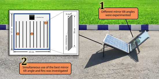
2.1. Equipment and Ambient Condition

The photovoltaic section of the solar energy laboratory in Jundi-Shapur University of Technology, Dezful, Iran, was established in 2018. The laboratory has both indoor and outdoor facilities. All tests of this paper were performed in the outdoor section, under the ambient conditions of October, 2021. The longitude and latitude of the location are 32.430052° and 48.365899°, respectively. In this site, there is no shadow of buildings, trees, etc., from 7:30 am to 6 pm. Since the variation in irradiation during daytime is an important parameter in efficiency assessment, sample values in the experiment days are illustrated in Figure 1. In addition, a histogram of the measured temperatures and emitted irradiations during the day are depicted in Figure 2. Accordingly, it is evidenced that the temperature range of 30 to 38 °C and radiation range of 700 to 1000 W/m2 have the largest portion during the test days.
All experiments were conducted using two 60 W multi-crystalline types of PV modules. Additionally, the electrical and thermal characteristics were monitored by a seven-channel thermal/electrical data-logger. The specifications of the equipment are given in Table 1.
In total, four thermal sensors were used. Three of them were attached at the back side of the PV module to have an average module temperature, and one was used to measure the ambient temperature. Aluminum fins were installed at the back side of the considered PV panel. This material has thermal conductivity of 204 W/m-K [30]. Totally, 10 fins were installed for the designated tests. The fins have rectangular geometry (50 cm × 4 cm) with 1 mm of thickness, as shown in Figure 3.

2.2. Experimental Procedure

It is obvious that the existence of soil on the front surface of PV modules decreases its electricity generation, significantly. In this regard, extensive experimental research was conducted by Kazem et al. [31,32,33,34,35], where they studied the effects of various dust substances, such as cement, sand, limestone, sawdust, fly ash, etc., on the output of the poly and mono crystalline PV modules. They found that different substances cause different negative impact values on PV performance. Moreover, it was shown that polycrystalline PV cell type is more affected than monocrystalline. Therefore, some other researchers focused on proposing and enhancing the cleaning methods to conquer the defect [36,37].
According to the mentioned important issue, in this study, the PV modules were fully cleaned before starting each test to avoid any discrepancy in data collecting and be confident about validity of the results.
The experimental section of this study can be classified into three main following phases. Moreover, a graphical overview of the research procedure is shown in Figure 4:
Stage 1.
Conduct tests with a bare PV panel, without mirror, with and without fins.
Stage 2.
Conduct tests with a bare PV panel and mirror. Find out the best mirror tilt angle.
Stage 3.
Conduct tests with a finned PV panel and mirror at the best-found tilt angle.
Furthermore, it should be noted that the PV panel tilt angle is kept at a 30° constant for all tests, based on the latitude value of the location. According to the above three stages, a total of six tests were selected among all performed tests, which are tabulated in Table 2. Moreover, and as a sample demonstration, an actual view of two cases is illustrated by Figure 5. It is necessary to state that several mirror tilt angles were experimented with, and three cases of 20°, 30°, and 40° were selected as the best ones to explore further.

3. Governing Equations

3.1. Energy Efficiency Calculations

Based on the first law of thermodynamics, energy cannot be created, instead can only be converted to other forms of energy. Therefore efficiency, defined as the proportion of useful energy output to input energy, is an important consideration in all energy applications. In this study, the input power of energy ( P i n ) for a PV panel is obtained from the electromagnetic radiation emitted by the sun, which can be calculated by [8]:
P i n = A e f f G
where A e f f and G stand for the effective photovoltaic cell area in (m2) and the normal irradiance of the sun in (W/m2), respectively. The effective PV cell area is calculated by the apparent panel area multiplied by a packing factor provided by the manufacturer.
In this study, the output power of energy ( P o u t ) from the PV panel is the produced electrical power calculated by Equation (2) [38]:
P o u t = V I
where V and I stand for voltage in (V) and current in (A), respectively. The mentioned parameters are accessible through the data logger measurements. Finally, the electrical efficiency of PV panels ( η ) can be obtained by [39,40]:
η e l = VI A e f f G  
Additionally, the power of lost heat from the cell interface, which is equipped with 10 rectangular fins at the back of the panel (Figure 3), could be calculated by [41]:
P t h = h A ( T c e l l T a m b )
where h, A, and T c e l l are the free convective heat transfer coefficient in W/m2K, surface area of panel and fins in m2, and cell temperature in K, respectively. Heat transfer coefficient is considered as [42]:
h = k   N u L
where L and K stand for width of cell in (m) and heat conduction coefficient in (W/mK), respectively. From ref. [43], the following relation is selected to calculate the dimensionless Nusselt number for the natural convection of mentioned geometry based on Grashof and Prandtl numbers.
N u = 0.59   ( G r   P r ) 0.25
G r = g   β   ( T c e l l T a m b ) ν 2
P r = C p   μ K

3.2. Exergy Efficiency Calculation

A comparison of the efficiencies of different energy conversion processes sets the stage for the second law of thermodynamics. Actually, the exergy ( E x ) is the useful portion of energy, which can be used, or the maximum available work, which is equal to the Helmholtz free energy variations (∆A) at a constant ambient temperature.
As it is shown in Figure 6, the PV panel is a closed system with one energy inlet as sun radiation and two energy outlets as waste thermal energy and electrical work. The rate of thermal exergy could be calculated as:
E ˙ x = Q ˙ ( 1 T a m b T )
where Q ˙ is the rate of heat transfer from the system, T is temperature of system, and Tamb is ambient temperature. Therefore, the input rate of exergy, which is obtained from sun radiation, is calculated by the presented equation by Jefer [44]:
E x ˙ s u n = G A e f f ( 1 T a m b T s u n )
where T s u n is the equivalent surface temperature of the sun which is reported as 5800 K [45]. The output rate of exergy of waste heat energy from the panel surface to the ambient can be calculated by [46]:
E x ˙ t h = P t h ( 1 T a m b T c e l l )
The rate of output exergy of electrical work ( E x ˙ e l e ) is equal to the rate of electrical power [47]. At the end, the exergy efficiency of the system is estimated by [48]:
η E x = VI + ( h   A ( T c e l l T a m b ) ) ( 1 T a m b T c e l l )   A e f f G ( 1 T a m b T s u n ) .

3.3. Entropy Generation Calculation

The irreversibility of PV panels can be estimated by entropy generation. The only thing responsible for the entropy generation of the mentioned closed system is heat transfer from the sun to the panel and from the panel to the ambient. So the relation of (13) is suggested for calculation of rate of entropy generation [43]:
S ˙ g e n = P i n P t h T a m b .

4. Uncertainty Analysis

The measuring equipment always has some unavoidable inaccuracies. Therefore, in any experimental engineering research, it is important to check and report the uncertainty values of the results. In this paper, the uncertainty analysis was calculated by the presented method in our previous article [49], as:
w R = ( R x 1 w 1 ) 2 + ( R x 2 w 2 ) 2 + + ( R x n w n ) 2 .
In the above equation, w R reports the sum of uncertainty in the presented results, R, is known as a function of the independent variables of x 1 ,   x 2 ,   ,   x n , and finally, the uncertainty value of independent parameters is shown by w 1 ,   w 2 ,   ,   w n . For each considered variable, the uncertainty value is calculated by dividing the accuracy value of the relevant sensor by the smallest obtained value of the considered variable. Therefore, for this study, the equivalent uncertainty was found as less than 1.82%. This section is divided by subheadings. It must provide a precise and brief description of the results, their interpretation, as well as the experimental conclusions that can be drawn.

5. Results and Discussion

5.1. Temperature Variations

As the first step, the temperature variation in the PV module versus time is investigated by Figure 7. As evidence, the cases equipped with aluminum fins attained to lower temperature level. Accordingly, the average values of all cases for the midday (12:00′ to 13:00′) are listed in Table 3. Therefore, a temperature difference of 10.2 °C was observed between the PV + fin case and the conventional one because of the higher heat transfer rate from back side of the PV panel to the environment while receiving the same irradiation. Another obtained conclusion of the graph is the influence of the reflector on the PV module temperature, which has an increment effect that was expected due to it receiving more irradiation.

5.2. Energy Analysis

As declared in the last paragraph of the introduction, the main purpose of the study is to increase the electricity production of the PV modules by implementing both installing aluminum fins from one hand, and using mirrors on the other. Therefore, the output power calculation plays a beneficial role in finding out more about the performance of each case. In Figure 8, the variations of output power are reported, almost from sunrise to sunset. The first task is to have a comparison between the cases of without fins and with reflector. As a result, the case of using a mirror with a tilt angle of 30° in front of the PV module shows the highest production because of it gaining more energy from the same sun radiation due to the optimum angle of the mirror relative to the average sun radiation. Therefore, according to the stage 3 of the described experimental procedure in Section 2.2, the next experiment should be performed on the simultaneous use of fins and a reflector with a tilt angle of 30°. So, as is clearly seen in the magnifier view of Figure 8, two cases integrated with fins build up the highest electrical output power, due to the extended area, for heat transfer, which leads to a higher rate of cooling for the cell surface. The cases of PV 30 + Fin and PV + Fin reached to 49.6 W and 48.11 W at 13:00′, respectively. While the conventional PV panel, as the weakest case, attained 43.9 W at the same time. Furthermore, the advantage of mounting fins rather than using a reflector is obvious.
The electrical efficiency is another parameter that is investigated here by Figure 9. Again, a magnifier shot is presented to have a better sight of the midday, but the assessment of the electrical efficiency has some challenges in it because of the dependency of the nominator and denominator of the electrical efficiency equation (see Equation (3)). The mentioned dependency let us know about how the inputs affect the outputs. Accordingly, using a reflector has simultaneous effects on the nominator and denominator because of increment in cell temperature, which leads to lower output power and the gaining of higher irradiation, respectively. So, it is important to find out about the balance of A e f f   .   G and VI.
To assess the results, it is clear that for both cases of 20° and 40°, an increase in the emitted irradiation did not have a positive effect on the electrical efficiency. In contrast, the case of 30° shows a different behavior and a positive result is seen. Then, the evaluation of fin-integrated cases must be considered, too. Accordingly, mounting fins has no effect on the denominator of Equation (3), and is only influenced on its nominator, which is the output power due to lowering the surface temperature. As a result, the case of PV 30 + Fin illustrates the highest electrical efficiency value. As a complementary conclusion for this section, Figure 10 is depicted. In this column graph, the arithmetic average values of all cases in terms of electrical efficiency and produced power are exhibited. The advantage of PV 30 + Fin is proven again by giving attention to Figure 8.

5.3. Exergy Analysis and Entropy Generation

There are two kinds of output exergies in PV systems: electrical and thermal. Both of them were discussed in Section 3.2, in detail. As described, the electrical exergy is equal to electrical energy, which is the output power. However, in this part, the thermal aspect of the exergy is considered. Therefore, it is not without grace to refer to the exergy definition: in any energy system, an amount of accessible energy, which can potentially be turned into useful work, is known as the exergy. Therefore, the thermal exergy can be calculated, just when the obtained heat is employed in a secondary purpose, e.g., a performed work by Chamkha et al. [50], which used the mentioned heat for a solar desalination system. In this study, the absorbed heat by fins was dissipated to the ambient medium. In a more accurate explanation, the absorbed heat is out of reach. Therefore, it cannot be considered in the calculation. Accordingly, the thermal exergy of the system is zero ( E x ˙ t h = 0 ). Unfortunately, in some papers it was took into account [51,52,53,54]. So, the exergy efficiency will be the same as electrical efficiency, as observed in Figure 9.
According to the definition, the entropy, illustrates the amount of irreversibilities in the system. As is easily found from Figure 11, the conventional PV and PV 30 + Fin illustrates the highest and lowest entropy generation, respectively. In a quantitative description, the best case attained up to 1.63% lower entropy generation. Furthermore, the columns of this figure have inverse behavior with the output power columns of Figure 10, so that the higher the electricity power generation, the lower the entropy generation.

6. Conclusions

The effect of the simultaneous use of installing aluminum fins as heat sink and mirrors as reflectors were experimentally concerned in this paper. The former was used as a coolant of PV modules and the latter as an irradiation-emitting riser. The tests were conducted in the hot climate of Dezful, Iran. Firstly, different mirror tilt angles were experimented with, and it was understood that 30° is the best one. Then, 10 fins were mounted on the back side of the panel, incorporated with this optimum mirror tilt angle, and a significant improvement was observed. The following explained the major results of the study:
  • Although the use of a mirror increased the obtained radiation by the PV panel, but the temperature of PV cells increased too, so that in the midday, the case of PV 30 attained to about 3 °C more of a temperature in comparison with the conventional one. However, the results show a positive outcome in the system, and 2.2 W more output power was measured for the mentioned case. Moreover, when the fins were also added to this case (PV 30 + fin), the output power was 4.1 W more than the conventional one due to lower PV temperatures at higher irradiations.
  • Dual behavior of the increase in emitted irradiation and surface temperature for the cases of mirrors integrated on the electrical efficiency was explored because of the obtaining of more radiation at the same condition. Afterward, it was illustrated that PV 30 has lower electrical efficiency than the conventional case, and when fins were also used (PV 30 + fin), the electrical efficiency of the panel was more than the conventional one due to a higher heat transfer rate in the presence of fins, which leads to lower PV cell temperature.
  • Calculation of both electrical and thermal exergies was discussed in detail, and the mistake made by some scholars was described. Then, the generation in entropy as one of the important thermodynamic concepts was calculated, too. Consequently, the case of PV 30 + fin showed 1.6% lower entropy generation compared with the base case.
As the final statement, some proposals are presented for scholars who want to develop the border of this scientific field:
  • Simultaneous application of phase change material and reflectors to enhance the output power of PV panels.
  • Assisting of artificial intelligence (AI) techniques to find optimum features of the investigated system, such as; surrounding conditions, PV tilt angle, mirror dimensions, mirror tilt angle, fin numbers, etc.
  • Performing of the life cycle assessment (LCA), energy payback time (EPBT), and environmental evaluation to find out the economic justification of the investigated system.

Author Contributions

Conceptualization, M.F. and M.L.; methodology, M.F.; validation, A.H.S.; formal analysis, M.F. and M.L.; investigation, M.F. and A.H.S.; data curation, M.F.; writing—original draft preparation, M.F.; writing—review and editing, M.L. and A.H.S.; visualization, A.H.S.; supervision, M.L.; project administration, M.L.; funding acquisition, A.H.S.; All authors have read and agreed to the published version of the manuscript.

Funding

This research received no external funding.

Institutional Review Board Statement

Not applicable.

Informed Consent Statement

Not applicable.

Data Availability Statement

Not applicable.

Conflicts of Interest

The authors declare no conflict of interest.

References

  1. Ghasemikafrudi, E.; Yousefi, S.; Goodarzvand-Chegini, F. Environmental Study of Waste Energy Recovery by Using Exergy and Economic Analysis in a Fluid Catalytic Cracking Unit. Adv. Environ. Technol. 2017, 3, 229–242. [Google Scholar]
  2. El-Mahallawi, I.; Elshazly, E.; Ramadan, M.; Nasser, R.; Yasser, M.; El-Badry, S.; Elthakaby, M.; Oladinrin, O.T.; Rana, M.Q. Solar PV Panels-Self-Cleaning Coating Material for Egyptian Climatic Conditions. Sustainability 2022, 14, 11001. [Google Scholar] [CrossRef]
  3. Al-Kouz, W.; Al-Dahidi, S.; Hammad, B.; Al-Abed, M. Modeling and Analysis Framework for Investigating the Impact of Dust and Temperature on PV Systems’ Performance and Optimum Cleaning Frequency. Appl. Sci. 2019, 9, 1397. [Google Scholar] [CrossRef] [Green Version]
  4. Anwar, K.; Deshmukh, S.; Renikindhi, S. Life-Cycle-Assessment Based Design of a Standalone Photovoltaic System: A Case Study Using a Theoretical and Numerical Approach. J. Braz. Soc. Mech. Sci. Eng. 2021, 43, 83. [Google Scholar] [CrossRef]
  5. Nnamchi, S.; Nnamchi, O.; Nwaigwe, K.; Jagun, Z.; Ezenwankwo, J. Effect of Technological Mismatch on Photovoltaic Array: Analysis of Relative Power Loss. J. Renew. Energy Environ. 2021, 8, 77–89. [Google Scholar]
  6. Sisodia, A.K. Impact of Bird Dropping Deposition on Solar Photovoltaic Module Performance: A Systematic Study in Western Rajasthan. Environ. Sci. Pollut. Res. 2019, 26, 31119–31132. [Google Scholar] [CrossRef]
  7. Agyekum, E.B.; Praveenkumar, S.; Alwan, N.T.; Velkin, V.I.; Shcheklein, S.E.; Yaqoob, S.J. Experimental Investigation of the Effect of a Combination of Active and Passive Cooling Mechanism on the Thermal Characteristics and Efficiency of Solar PV Module. Inventions 2021, 6, 63. [Google Scholar] [CrossRef]
  8. Hasan, A.; Mccormack, S.J.; Huang, M.J.; Norton, B. Energy and Cost Saving of a Photovoltaic-Phase Change Materials (PV-PCM) System through Temperature Regulation and Performance Enhancement of Photovoltaics. Energies 2014, 7, 1318–1331. [Google Scholar] [CrossRef] [Green Version]
  9. Awda, L.; Khalaf, Y.; Salih, S. Analysis of Temperature Effect on a Crystalline Silicon Photovoltaic Module Performance. Int. J. Eng. 2016, 29, 722–727. [Google Scholar]
  10. Shiravi, A.H.; Firoozzadeh, M.; Lotfi, M. Experimental Study on the Effects of Air Blowing and Irradiance Intensity on the Performance of Photovoltaic Modules, Using Central Composite Design. Energy 2022, 238, 121633. [Google Scholar] [CrossRef]
  11. Araneo, R.; Grasselli, U.; Celozzi, S. Assessment of a Practical Model to Estimate the Cell Temperature of a Photovoltaic Module. Int. J. Energy Environ. Eng. 2014, 5, 72. [Google Scholar] [CrossRef] [Green Version]
  12. Siddiqui, R.; Bajpai, U. Correlation between Thicknesses of Dust Collected on Photovoltaic Module and Difference in Efficiencies in Composite Climate. Int. J. Energy Environ. Eng. 2012, 3, 26. [Google Scholar] [CrossRef] [Green Version]
  13. Al-Nimr, M.D.A.; Kiwan, S.; Sharadga, H. Simulation of a Novel Hybrid Solar Photovoltaic/Wind System to Maintain the Cell Surface Temperature and to Generate Electricity. Int. J. Energy Res. 2018, 42, 985–998. [Google Scholar] [CrossRef]
  14. Firoozzadeh, M.; Shiravi, A.H.; Lotfi, M.; Aidarova, S.; Sharipova, A. Optimum Concentration of Carbon Black Aqueous Nanofluid as Coolant of Photovoltaic Modules: A Case Study. Energy 2021, 225, 120219. [Google Scholar] [CrossRef]
  15. Chaichan, M.T.; Mahdi, M.T.; Kazem, H.A.; Al-Waeli, A.H.; Fayad, M.A.; Al-Amiery, A.A.; Isahak, W.N.R.W.; Kadhum, A.A.H.; Takriff, M.S. Modified Nano-Fe2O3-Paraffin Wax for Efficient Photovoltaic/Thermal System in Severe Weather Conditions. Sustainability 2022, 14, 12015. [Google Scholar] [CrossRef]
  16. Mohd Shatar, N.; Abdul Rahman, M.A.; Muhtazaruddin, M.N.; Shaikh Salim, S.A.Z.; Singh, B.; Muhammad-Sukki, F.; Bani, N.A.; Mohd Saudi, A.S.; Ardila-Rey, J.A. Performance Evaluation of Unconcentrated Photovoltaic-Thermoelectric Generator Hybrid System under Tropical Climate. Sustainability 2019, 11, 6192. [Google Scholar] [CrossRef] [Green Version]
  17. Hasan, H.A.; Sherza, J.S.; Mahdi, J.M.; Togun, H.; Abed, A.M.; Ibrahim, R.K.; Yaïci, W. Experimental Evaluation of the Thermoelectrical Performance of Photovoltaic-Thermal Systems with a Water-Cooled Heat Sink. Sustainability 2022, 14, 10231. [Google Scholar] [CrossRef]
  18. Tabaei, H.; Ameri, M. Improving the Effectiveness of a Photovoltaic Water Pumping System by Using Booster Reflector and Cooling Array Surface by a Film of Water. Iran. J. Sci. Technol. Trans. Mech. Eng. 2015, 39, 51–60. [Google Scholar]
  19. Firoozzadeh, M.; Shiravi, A.H. Simultaneous Use of Porous Medium and Phase Change Material as Coolant of Photovoltaic Modules; Thermodynamic Analysis. J. Energy Storage 2022, 54, 105276. [Google Scholar] [CrossRef]
  20. González-Peña, D.; Alonso-Demiguel, I.; Díez-Mediavilla, M.; Alonso-Tristán, C. Experimental Analysis of a Novel PV/T Panel with PCM and Heat Pipes. Sustainability 2020, 12, 1710. [Google Scholar] [CrossRef] [Green Version]
  21. Grubišić-Čabo, F.; Nižetić, S.; Marinić Kragić, I.; Čoko, D. Further Progress in the Research of Fin-Based Passive Cooling Technique for the Free-Standing Silicon Photovoltaic Panels. Int. J. Energy Res. 2019, 43, 3475–3495. [Google Scholar] [CrossRef]
  22. Fudholi, A.; Zohri, M.; Jin, G.L.; Ibrahim, A.; Yen, C.H.; Othman, M.Y.; Ruslan, M.H.; Sopian, K. Energy and Exergy Analyses of Photovoltaic Thermal Collector with ∇-Groove. Sol. Energy 2018, 159, 742–750. [Google Scholar] [CrossRef]
  23. Firoozzadeh, M.; Shiravi, A.H.; Chandel, S.S. Experimental Analysis of Enhancing Cooling of Photovoltaic Modules Using Straight and Zig-Zag Fins. J. Therm. Anal. Calorim. 2022, 147, 8827–8839. [Google Scholar] [CrossRef]
  24. Sedaghat, A.; Karami, M.; Eslami, M. Improving Performance of a Photovoltaic Panel by Pin Fins: A Theoretical Analysis. Iran. J. Sci. Technol. Trans. Mech. Eng. 2020, 44, 997–1004. [Google Scholar] [CrossRef]
  25. Tahmasbi, M.; Siavashi, M.; Norouzi, A.M.; Doranehgard, M.H. Thermal and Electrical Efficiencies Enhancement of a Solar Photovoltaic-Thermal/Air System (PVT/Air) Using Metal Foams. J. Taiwan Inst. Chem. Eng. 2021, 124, 276–289. [Google Scholar] [CrossRef]
  26. Tabasi, S.; Yousefi, H.; Noorollahi, Y.; Aramesh, M. A Detailed Investigation and Performance Optimization of a Photovoltaic Panel Integrated with a Reflecting Mirror. Appl. Therm. Eng. 2019, 160, 114074. [Google Scholar] [CrossRef]
  27. Malik, P.; Chandel, S.S. Performance Enhancement of Multi-Crystalline Silicon Photovoltaic Modules Using Mirror Reflectors under Western Himalayan Climatic Conditions. Renew. Energy 2020, 154, 966–975. [Google Scholar] [CrossRef]
  28. Agrawal, M.; Kumar, A.; Chowdhury, A. A Detailed Simulation-Based Study on the Effect of Mirror Integration on PV Module (S) with Analysis of Different Wind Flow Scheme. Sol. Energy 2021, 222, 129–144. [Google Scholar] [CrossRef]
  29. Palaskar, V.N.; Deshmukh, S.P.; Pandit, A.B. Design and Performance Analysis of Reflectors Attached to Commercial PV Module. Int. J. Renew. Energy Res. (IJRER) 2014, 4, 240–245. [Google Scholar]
  30. Shiravi, A.H.; Firoozzadeh, M. Performance Assessment of a Finned Photovoltaic Module Exposed to an Air Stream; an Experimental Study. J. Braz. Soc. Mech. Sci. Eng. 2022, 44, 535. [Google Scholar] [CrossRef]
  31. Kazem, H.A.; Chaichan, M.T.; Al-Waeli, A.H. A Comparison of Dust Impacts on Polycrystalline and Monocrystalline Solar Photovoltaic Performance: An Outdoor Experimental Study. Environ. Sci. Pollut. Res. 2022, 29, 88788–88802. [Google Scholar] [CrossRef]
  32. Kazem, H.A.; Chaichan, M.T.; Al-Waeli, A.H.; Sopian, K. Effect of Dust and Cleaning Methods on Mono and Polycrystalline Solar Photovoltaic Performance: An Indoor Experimental Study. Sol. Energy 2022, 236, 626–643. [Google Scholar] [CrossRef]
  33. Kazem, H.A.; Al-Waeli, A.H.; Chaichan, M.T.; Sopian, K. Modeling and Experimental Validation of Dust Impact on Solar Cell Performance. Energy Sources Part A Recovery Util. Environ. Eff. 2022, 1–17. [Google Scholar] [CrossRef]
  34. Kazem, H.A.; Yousif, J.H.; Al-Balushi, H.; Abuhmaidan, K.; Al-Badi, R. Artificial Neural Network Modelling and Experimental Evaluation of Dust and Thermal Energy Impact on Monocrystalline and Polycrystalline Photovoltaic Modules. Energies 2022, 15, 4138. [Google Scholar]
  35. Kazem, H.A.; Chaichan, M.T.; Al-Waeli, A.H.; Sopian, K.; Darwish, A.S.K. Evaluation of Dust Elements on Photovoltaic Module Performance: An Experimental Study. Renew. Energy Environ. Sustain. 2021, 6, 30. [Google Scholar] [CrossRef]
  36. Beygzadeh, S.; Beygzadeh, V.; Beygzadeh, T. Thermodynamic and Economic Comparison of Photovoltaic Electricity Generation with and without Self-Cleaning Photovoltaic Panels. Energy Equip. Syst. 2019, 7, 263–270. [Google Scholar]
  37. Nabil, T.; Mansour, T.M. Augmenting the Performance of Photovoltaic Panel by Decreasing Its Temperature Using Various Cooling Techniques. Results Eng. 2022, 15, 100564. [Google Scholar] [CrossRef]
  38. Akbari, H.; Browne, M.C.; Ortega, A.; Huang, M.J.; Hewitt, N.J.; Norton, B.; Mccormack, S.J. Efficient Energy Storage Technologies for Photovoltaic Systems. Sol. Energy 2019, 192, 144–168. [Google Scholar] [CrossRef]
  39. Nasrin, R.N.; Hossain, M.S. Numerical Analysis of Photovoltaic Power Generation in Different Locations of Bangladesh. J. Comput. Appl. Res. Mech. Eng. (JCARME) 2021, 10, 373–389. [Google Scholar]
  40. Pagodaripour, A.; Ghasemkhani, A.; Ghazizade-Ahsaee, H.; Namjo, A. The Assessment and Experimental Study of Photovoltaics Panel by Spraying Water (Case Study: Kerman, Iran). Energy Equip. Syst. 2020, 8, 389–399. [Google Scholar]
  41. Sardarabadi, M.; Passandideh-Fard, M.; Heris, S.Z. Experimental Investigation of the Effects of Silica/Water Nanofluid on PV/T (Photovoltaic Thermal Units). Energy 2014, 66, 264–272. [Google Scholar] [CrossRef]
  42. Saffarian, M.R.; Moravej, M.; Doranehgard, M.H. Heat Transfer Enhancement in a Flat Plate Solar Collector with Different Flow Path Shapes Using Nanofluid. Renew. Energy 2020, 146, 2316–2329. [Google Scholar] [CrossRef]
  43. Dincer, I. 1.7 Energy and Exergy Efficiencies. In Comprehensive Energy Systems; Dincer, I., Ed.; Elsevier: Oxford, UK, 2018; pp. 265–339. [Google Scholar]
  44. Jeter, S.M. Maximum Conversion Efficiency for the Utilization of Direct Solar Radiation. Sol. Energy 1981, 26, 231–236. [Google Scholar] [CrossRef]
  45. Hosseinzadeh, M.; Sardarabadi, M.; Passandideh-Fard, M. Energy and Exergy Analysis of Nanofluid Based Photovoltaic Thermal System Integrated with Phase Change Material. Energy 2018, 147, 636–647. [Google Scholar] [CrossRef]
  46. Firoozzadeh, M.; Shiravi, A.H.; Shafiee, M. Thermodynamics Assessment on Cooling Photovoltaic Modules by Phase Change Materials (PCMs) in Critical Operating Temperature. J. Therm. Anal. Calorim. 2021, 144, 1239–1251. [Google Scholar] [CrossRef]
  47. Chow, T.T.; Pei, G.; Fong, K.F.; Lin, Z.; Chan, A.L.S.; Ji, J. Energy and Exergy Analysis of Photovoltaic–Thermal Collector with and without Glass Cover. Appl. Energy 2009, 86, 310–316. [Google Scholar] [CrossRef]
  48. Fudholi, A.; Zohri, M.; Rukman, N.S.B.; Nazri, N.S.; Mustapha, M.; Yen, C.H.; Mohammad, M.; Sopian, K. Exergy and Sustainability Index of Photovoltaic Thermal (PVT) Air Collector: A Theoretical and Experimental Study. Renew. Sustain. Energy Rev. 2019, 100, 44–51. [Google Scholar] [CrossRef]
  49. Lotfi, M.; Shiravi, A.H.; Firoozzadeh, M. Experimental Study on Simultaneous Use of Phase Change Material and Reflector to Enhance the Performance of Photovoltaic Modules. J. Energy Storage 2022, 54, 105342. [Google Scholar] [CrossRef]
  50. Chamkha, A.J.; Rufuss, D.; Kabeel, A.; Sathyamurthy, R.; Abdelgaid, M.; Manokar, A.M.; Madhu, B. Augmenting the Potable Water Produced from Single Slope Solar Still Using CNT-Doped Paraffin Wax as Energy Storage: An Experimental Approach. J. Braz. Soc. Mech. Sci. Eng. 2020, 42, 625. [Google Scholar] [CrossRef]
  51. Aberoumand, S.; Ghamari, S.; Shabani, B. Energy and Exergy Analysis of a Photovoltaic Thermal (PV/T) System Using Nanofluids: An Experimental Study. Sol. Energy 2018, 165, 167–177. [Google Scholar] [CrossRef]
  52. Akyuz, E.; Coskun, C.; Oktay, Z.; Dincer, I. A Novel Approach for Estimation of Photovoltaic Exergy Efficiency. Energy 2012, 44, 1059–1066. [Google Scholar] [CrossRef]
  53. Bayrak, F.; Oztop, H.F.; Selimefendigil, F. Effects of Different Fin Parameters on Temperature and Efficiency for Cooling of Photovoltaic Panels under Natural Convection. Sol. Energy 2019, 188, 484–494. [Google Scholar] [CrossRef]
  54. Eisapour, M.; Eisapour, A.H.; Hosseini, M.J.; Talebizadehsardari, P. Exergy and Energy Analysis of Wavy Tubes Photovoltaic-Thermal Systems Using Microencapsulated PCM Nano-Slurry Coolant Fluid. Appl. Energy 2020, 266, 114849. [Google Scholar] [CrossRef]
Figure 1. Moderate solar irradiance and ambient temperature of Dezful for the test days.
Sustainability 14 16986 g001
Figure 2. Ambient temperature and irradiation histogram of the experiment.
Sustainability 14 16986 g002
Figure 3. Exact location of thermal sensors and mounted fins at the back side of a PV panel.
Sustainability 14 16986 g003
Figure 4. An overview of the research procedure.
Sustainability 14 16986 g004
Figure 5. An actual view of the experiments.
Sustainability 14 16986 g005
Figure 6. Schematic of the considered closed system for exergy analysis.
Sustainability 14 16986 g006
Figure 7. Temperature variations during time.
Sustainability 14 16986 g007
Figure 8. Output power variations during time.
Sustainability 14 16986 g008
Figure 9. Electrical efficiency variations during time.
Sustainability 14 16986 g009
Figure 10. Average values of the electrical efficiency and output power for the experiment time.
Sustainability 14 16986 g010
Figure 11. Entropy generation in the midday (13:00′).
Sustainability 14 16986 g011
Table 1. Specifications of the experimental setup.
EquipmentParameter
PV panelManufacturer: Yingli Solar Co., Baoding, China
Nominal power output ( P M a x ) : 60 W
Nominal module efficiency ( η m ) : 14.4%
Voltage at P M a x ( V m p p ) : 18.47 V
Open-circuit voltage ( V O C ) : 22.86 V
Current at P M a x ( I m p p ) : 3.25 A
Short-circuit current ( I S C ) : 3.44 A
Temperature sensorModel: DS-18B20, China
Operating range: −55 to +125 °C
Accuracy: 0.1 °C
SolarimeterModel: TES-132, China
Operating range: 200–2000 W/m2
Accuracy: 1 W/m2
Table 2. List of experimental cases.
No.NameFinMirror
1Conventional PV××
2PV + Fin×
3PV 20×20°
4PV 30×30°
5PV 40×40°
6PV 30 + Fin30°
Table 3. Mean temperature of all cases for 12:00′ to 13:00′.
CaseMean Temperature (°C)
Conventional PV module69.5
PV 2071.6
PV 3073.2
PV 4070.1
PV + Fin59.3
PV 30 + Fin62.4
Publisher’s Note: MDPI stays neutral with regard to jurisdictional claims in published maps and institutional affiliations.

