Article

CFD Analysis of a Small-Scale Solar Chimney Exposed to Ambient Crosswind

by
Cristiana Brasil Maia
* and
Janaína de Oliveira Castro Silva
Department of Mechanical Engineering, Pontifícia Universidade Católica de Minas Gerais, Belo Horizonte 30535-901, Brazil
*
Author to whom correspondence should be addressed.
Sustainability 2022, 14(22), 15208; https://doi.org/10.3390/su142215208
Submission received: 21 September 2022 / Revised: 28 October 2022 / Accepted: 2 November 2022 / Published: 16 November 2022

Abstract

:
Solar chimneys are devices that use solar energy to generate a hot airflow that can be used for power production, the drying of agricultural products, and/or water desalination. The performance of a small-scale solar chimney is studied numerically. The computational domain includes the solar chimney, the ground, and the atmosphere. The turbulent airflow is simulated using the commercial CFD code Ansys Fluent. The only boundary conditions required for the simulation are the wind speed, the ambient temperature, and the absorbed energy from the ground, determined by an energy balance in the system. The system was simulated for one day in the summer in the city of Belo Horizonte, Brazil. The ambient crosswind plays an important role in the velocity and temperature. The velocity inside the solar chimney increased with the wind speed, increasing the heat transfer and decreasing the airflow temperature. When the wind speed increased from 0 to 10 m/s, the outlet velocity increased from 1 to 4 m/s, and the outlet temperature decreased from 313 to 304 K.

1. Introduction

The depletion of conventional energy resources is a problem facing the world nowadays, leading to the search for renewable energy sources [1]. Solar energy arises as a clean and abundant source with the potential to meet world energy requirements with free emissions [2]. Solar chimneys use solar energy to generate a hot airflow, consisting of three main parts: a solar collector, an absorber plate, and a chimney. For power generation applications, they also comprise a wind turbine coupled with a generator. The operational principle is very simple: the solar energy is converted into thermal energy in the collector, and subsequently, into kinetic energy [3]. The kinetic energy can be converted into electrical energy in the wind turbine in large structures.
According to [4], the power production scales with the product of the collector area and chimney height, indicating that if two similar plants were compared, a cubic scaling is obtained for the power. Therefore, large structures are required to generate electric power at competitive prices [5]. Small-scale devices can be used to dry agricultural products [6], for space heating [7], or for natural ventilation [8]. Maia et al. [6] evaluated the drying of bananas inside a small-scale solar chimney, using an analysis based on the first and second laws of thermodynamics, comparing the performance of the system with and without load. Monghasemi and Vadiee [7] presented an overview of the integration of solar chimneys to improve the level of thermal comfort in residential sectors. Maghrabie et al. [8] assessed the potential design and operating parameters of solar chimneys for natural ventilation.
Solar chimneys, nevertheless, present very low efficiency [9], which can be improved by combining power generation with other uses in hybrid plants. According to [10], PV systems, industrial waste, or flue gases can be integrated into the plants, or the plants can be combined with solar dryers, desalination plants, and cooling tower applications.
The power generation and the overall efficiency of the plant depend on several factors. The geometry plays an important role, with it being demonstrated that the most important parameters are the tower dimensions as they cause the most significant variations in the flow behavior [11]. The collector diameter is also a very important factor since it changes the energy absorbed by the system. Besides the geometry, other important factors are the heat transfer coefficients, the pressure potential, and the turbine pressure drop [10].
Several studies have been conducted to determine the influence of the factors on the performance of the system and the airflow characteristics, divided into experimental, analytical, and numerical studies. The first experimental study was the Manzanares plant, with a peak output of 50 kW built in 1981/82 in Spain [12], used as a reference for the majority of the works. The construction of the plant and its basic principles are described by [13] and preliminary test results are presented by [14]. Since its construction, other experimental studies were performed but mainly restricted to laboratory scale.
A prototype of a solar chimney, with a height of 12.3 m, was tested for nine months, and the results of temperature, velocity, solar radiation, and humidity are presented by [15]. A prototype with a tower height of 3 m and a collector diameter of 3 m was constructed in Iran [16]. The performance of the system was experimentally evaluated using different materials and different dimensional parameters. Experimental data for the temperatures and velocities of the airflow inside a solar chimney with a tower height of 12 m and a collector diameter of 10 m are described by [17]. A detailed analysis of experimental data on the temperature inside a solar chimney in China is given in [18]. The tower is 8 m tall, made from PVC drainpipes, and the collector has a diameter of 8 m.
Mathematical models represent the thermal analysis of the components of the system, including energy and exergy balances [19,20,21]. An exergetic analysis of a solar chimney was first presented by [21]. The author described a simplified mathematical model of a solar chimney to demonstrate the feasibility of the application of exergetic analysis in this system. The results were presented based on several assumptions, not on experimental data. A thermodynamic analysis based on experimental data inside a small-scale solar chimney prototype was performed in [20]. The energy and exergy rates inside the system were estimated. The prototype was designed to dry agricultural products. Later, a thermodynamic analysis for the system with and without load was developed in [6], for the drying of bananas. A 3D numerical analysis of a solar chimney was performed using the geometry of the Manzanares prototype and Tehran climate data [19]. The energy and exergy efficiencies varied from 3.5 to 93.3% and 2.0 to 29.0%, respectively.
Computational fluid dynamics (CFD) models describe the behavior of the airflow inside the solar chimney and represent a suitable method to evaluate the influence of the geometry and boundary conditions on the system performance.
A CFD analysis of a small-scale solar chimney was performed by Yapici [22], considering steady-state conditions and a constant solar radiation heat flux on the collector roof and absorber. The results were compared to experimental data from the literature, and, after validation, the authors evaluated different configurations for the system aiming to find the maximum power production. Fallah and Valipour [23] assessed velocity and temperature fields inside a small-scale sloped solar chimney using a 3D simulation. Prescribed values of solar radiation and correlations from literature to the heat transfer coefficients were used. The simulation was validated by experimental data from the literature.
Cuce et al. [24] evaluated the influence of the chimney height on the maximum velocity reached by the airflow, the pressure difference around the turbine, temperature rise in the collector, power output, and plant efficiency. The influence of solar radiation on the maximum velocity was also evaluated. The analysis was performed considering steady-state conditions, neglecting changes in climatic conditions. A constant value for solar radiation was also assumed. The dimensions of the plant were defined as the ones from the Manzanares plant. Torabi et al. [25] studied the influence of geometric parameters, such as collector radius and divergent angle, and thermal boundary conditions on the performance of a solar chimney. Prescribed values for the heat flux and convective heat transfer coefficient were assumed. The Manzanares plant dimensions were selected, and the results were compared to numerical results from the literature.
Numerous studies can be found regarding numerical simulations of solar chimneys. Pradhan et al. [26] present a literature review of the studies concerning the design and performance of solar chimney power plants, focusing mainly on maximum power and efficiency. Kasaeian et al. [27] and Das and Chandramohan [10], present a comprehensive review of the solar chimney technology, including thermodynamic analyses, and experimental and numerical works, discussing the challenges and opportunities of the plants. Regarding CFD analyses, the authors concluded that most of the studies performed simulations without considering the effect of the turbine on the airflow. Moreover, further focus should be on the development of models to predict the power potential of the solar chimney by changing its dimensions.
Another gap in the literature is the use of boundary conditions. Most works from the literature adopt fixed values for the incident solar radiation and convective heat transfer coefficients, developing steady-state conditions analyses. Some works use fixed values for the inlet velocity or mass flowrate when it is well-known that the airflow is generated by buoyancy forces; therefore, the velocity depends on the incident solar radiation. In general, the solution domain comprises only the solar chimney and sometimes the ground under the solar collector. A few works were found using a computational box to represent the atmosphere outside the device when the influence of crosswind on solar chimneys is evaluated. The first analysis was developed by [28,29], evaluating the effect of the crosswind on the pressure, temperature, and velocity distribution, and the output power of a solar chimney with the dimensions of the Manzanares prototype. The boundary condition used on the ground surface is a radiation flux depending on the intensity of the incident solar radiation. The velocity at the inlet was assumed as fitting the logarithmic law of the atmospheric boundary layer proposed by Prandtl in 1932, depending on the ground surface shear stress and the aerodynamic roughness length of the ground. Later, the same boundary condition for the velocity was adopted by [30] to simulate large-scale solar chimneys, using constant values for the heat flux on the ground surface. The assessment of the influence of strong wind speeds was performed by [31], using prescribed values for the incident solar radiation.
More recently, a tilted solar chimney was studied in [32], using the same boundary conditions of Shen et al. An experimental and numerical analysis of a small solar chimney was carried out [33], considering as boundary conditions for the numerical analysis of the logarithmic profile for the inlet velocity, an empirical correlation for the convective heat transfer between the cover and the ambient, and assuming the ground surface as adiabatic. An experimental analysis of a small solar chimney was performed by [32] to establish dimensional parameters to predict the output of large-scale dimensions. The effect of the wind speed on the exit updraft velocity was experimentally evaluated in [34]. In view of the shortcomings of the above research, this paper puts forward a numerical analysis of the influence of the crosswind on a small-scale solar chimney, with simple boundary conditions. The only parameters needed are the wind speed, the ambient temperature, and the incident solar radiation, not requiring temperatures and heat transfer rates on the collector or the ground. In this work, a numerical analysis of the airflow inside a small-scale solar chimney is developed. The incident solar radiation was estimated for the city of Belo Horizonte, Brazil, and, based on the predicted value, the heat absorbed by the ground was determined by an energy balance considering the optical properties of the materials, such as ground absorptance and collector transmittance. The computational domain includes the solar chimney, the ground, and the atmosphere, allowing the prediction of the system characteristics having as input data only the ambient temperature, the wind speed, and the absorbed heat from the ground. It was not necessary to provide a value for the inlet velocity, determined by the analysis. It was also possible to evaluate the influence of the crosswind on the velocity distribution inside the system, for wind speeds from 0 to 10 m/s.

2. Materials and Methods

The mathematical model is divided into the governing equations used in the CFD analysis, and the energy balance for the system.

2.1. Governing Equations

The governing equations for mass, momentum, and energy are given by [35]
  ( ρ · v ) = 0 ,
  ( ρ · v ·   v ) = p +   ( μ [ ( v + v T ) 2 3 · v   I ] ) + ρ   g ,
  · ( v ( ρ E + p ) ) = ( k e f f T h J + ( μ [ ( v + v T ) 2 3 · v   I ] · v ) ) ,
In Equations (1)–(3), ρ stands for density, μ for dynamic viscosity, k e f f for the eddy thermal diffusivity, v for velocity, p for pressure, E for energy, and g for gravity.
To take into account the turbulent effects, the k-ε turbulence model was used, in which the turbulent viscosity is given by
μ t = ρ C μ k 2 ε .
C μ , k and ε represent an empirical constant, the turbulent kinetic energy, and the rate of dissipation of the turbulent kinetic energy, respectively. The main equations for the turbulence model are given by [35].
The k-ε turbulence model is the most used model for the study of solar chimneys [11,36,37]. Additionally, in an evaluation of the effect of the turbulence model on the simulation of solar chimneys, this model showed the best agreement with experimental results among the evaluated models [38].
The airflow inside the solar chimney is induced by natural convection. The Rayleigh number Ra is the dimensionless parameter that measures the intensity of the flow. It is defined by:
R a = g β Δ T L 3 α ν .
Δ T is the maximum temperature increase within the system. α is the thermal diffusivity, ν is the kinematic viscosity, β is the thermal expansion coefficient, and L is the collector height.

2.2. Energy Balance

Solar energy reaches the collector, and part of this energy reaches the ground and is transferred to the airflow. Considering an isotropic sky model, the absorbed energy by the ground S is the sum of the beam ( I b ), diffuse ( I d ) and ground-reflected components, as given by [39]
S = I b R b ( τ α ) b + I d R d ( 1 + cos β 2 ) + ρ g I ( τ α ) g ( 1 cos β 2 ) ,
( τ α ) represents the transmittance–absorptance for the beam (subscript b), diffuse (subscript d) and ground reflected (subscript g) components. β is the tilt angle of the collector (in this work, β = 0 ° ). ρ g is the ground reflectance, and R b represents the ratio between the solar radiation on a tilted surface and on a horizontal surface.
The absorbed energy from the ground is determined based on an energy balance in the system, as indicated in Figure 1.
The convective heat transfer from the airflow ( q c o n v , 3 ) and the radiative heat transfer from the ground surface ( q r a d , 1 ) to the collector surface are lost to the environment by convection ( q c o n v , 2 ) and radiation ( q r a d , 2 ). The energy transferred by the ground surface to the deeper layers by conduction ( q c o n d , 0 ) is given by the difference between the absorbed portion (S) of the incident solar energy, the convection heat transfer to the airflow ( q c o n v , 1 ), and the radiative heat transfers to the collector ( q r a d , 1 ) and to the environment ( q r a d , 3 ).
S q c o n v , 1 q r a d , 1 q r a d , 3 = q c o n d , 0 .
A complete description of the model is presented in [5]. Radiative heat transfers were modeled following classic models from the literature, as suggested by [39]. Convective heat transfer coefficients were adopted according to the literature on solar chimneys [40,41].

2.3. Computational Analysis

In this study, ANSYS Fluent software was used for simulation. The dimensions and properties of the prototype were defined as the ones of a small-scale prototype built in Belo Horizonte, Brazil [5]. The height and diameter of the tower are, respectively, 2.5 m and 0.2 m, and the height and diameter of the collector are, respectively, 0.1 m and 5 m. The tower walls are thermally insulated.
The computational domain used includes three different domains: the solar chimney, the ground, and the atmosphere, as indicated in Figure 2.
It was performed a mesh test to reach a mesh-independent solution. Three mesh configurations were used, and the most refined one, which was used for obtaining the results, had 117,137 nodes and 525,792 elements. This mesh was able to ensure grid independency. The mesh consisted of tetrahedral elements inside the geometry and prism elements on the walls, as suggested by [42].
The atmosphere around the solar chimney was modeled as a parallelepiped 10 m in width and 5 m in height, with air as an ideal gas, atmospheric pressure of 91.5 kPa (for the city of Belo Horizonte, Brazil), and prescribed ambient temperature. The upper and lower surface of the atmosphere were considered adiabatic. In the lateral surfaces, an opening condition was assumed, allowing the air to enter or leave the system. In one of the lateral faces, a prescribed value was assumed for the wind speed (Figure 3), varying from 0 to 10 m/s.
Since the airflow is generated by buoyance forces, the velocity in the radial direction is unknown [11], depending on the ambient conditions. The use of a computational box representing the atmosphere, as presented by [32], avoids the prescription of the velocity at the collector inlet. The velocity is obtained by the solution of the governing equations.
The ground was modeled as a continuous solid of brick, with 0.5 m of depth. At the beginning of the simulation, it was assumed a homogeneous temperature, equal to the ambient temperature. On the bottom surface, a no-slip condition and a fixed value for the temperature were considered. In the lateral surface, it was assumed a no-slip adiabatic condition.
Finally, the air inside the solar chimney was modeled as real gas. The tower wall was assumed adiabatic. The inlet and outlet of the solar chimney were modeled as opening conditions, which allow the air either to enter or leave the system, depending on the conditions. The collector surface and the ground surface were modeled as an interface without mass flow, allowing only energy transfers. At the ground surface, a prescribed value for the heat flux was adopted, corresponding to the absorbed energy from the ground, determined by Equation (6). The model for the absorbed energy from the ground takes into account the beam and diffuse components of the solar radiation and considers an isotropic sky model. A complete description of the model is given in [39]. The boundary conditions are summarized in Table 1.
Therefore, it is worth noting that the only values required as input data are ambient temperature, wind speed, and the energy absorbed by the ground, which makes the developed model global and easy to simulate for different locations.

3. Results

The results are presented for the 8th of February, at noon, corresponding to the middle of summer in the Southern Hemisphere. The input data are only the ambient temperature of 30.3 °C, corresponding to results from experimental data, and 565 W/m2 of energy absorbed by the ground, determined by Equation (6). The wind speed was prescribed. The first results were obtained with a wind speed initially defined as zero, but the influence of the wind speed was also assessed, by varying it from 0 to 10 m/s.
The distribution of the temperature inside the entire computational domain (atmosphere, solar chimney, and ground) is shown in Figure 4. Inside the solar chimney, it can be seen an increase in the air temperature towards the tower, caused by the heat transfer from the ground surface. The atmosphere temperature is nearly constant, except for the region close to the tower outlet. The air leaves the solar chimney at a temperature higher than the ambient temperature, and the heat is dissipated to the surroundings. On the ground, the temperature variation is only significant close to the ground surface.
In the tower, small variations in temperature were found, due to the thermal insulation assumption. Figure 5 and Figure 6 present the temperature distribution in the tower, in more detail. Figure 5 presents the temperature in a cross-section of the tower (variation with the x-axis), at a height corresponding to the beginning of the tower. The temperature profile is symmetric and approximately constant, except for the region close to the walls.
Figure 6 presents the temperature variation in the tower height, on the symmetry axis. The position y = 0 corresponds to the ground surface, where the temperature was higher due to the solar radiation absorption. The temperature decreased for higher heights. When the airflow reached the tower, the temperature remained approximately constant due to the thermal insulation condition.
The ground temperature decreased from the surface to the deeper layers, and it can be seen that at a small distance from the surface, the temperature reached ambient temperature. Figure 7 shows the temperature distribution along the ground. The temperature distribution is nearly exponential, consistent with the semi-infinite solid assumption for the ground. The ambient temperature was reached at a distance of 0.2 m.
The velocity field inside the solar chimney is shown in Figure 8. Under the collector, due to the higher cross-section area, the velocities were lower, increasing towards the tower, when the airflow was changed from radial to axial. Unlike the temperature, the velocity varied with height. For lower heights, the velocity at the center was higher, decreasing with the boundary layer development. At the top of the tower, the airflow exhibited the behavior of an almost fully developed flow. It is worth noting that the average velocity was constant, once the cross-sectional area did not vary in the tower. The airflow in the tower was turbulent, with a Reynolds number (based on the tower diameter) of approximately 1 × 10 5 .
Figure 9 presents the streamlines of the airflow. It is possible to see vortices inside the solar collector and random flow structures close to the tower.
The velocity profile at a height corresponding to the beginning of the tower is shown in Figure 10. Although turbulent, the profile is not the expected profile: flat in the center, dropping off sharply to zero at the wall, because the airflow is not yet fully developed. The development of the velocity in the tower, on the symmetry axis, is shown in Figure 11.
In the connection between the collector and the tower, the geometry imposes a sudden contraction on the airflow, forcing it to contract through a minimum diameter, and increasing the velocity [43], as shown in Figure 11. The transition between the collector and the tower is a region in which the airflow may detach from the wall [4]. This behavior is observed in Figure 12, with null shear stress in this region.
Figure 4, Figure 5, Figure 6, Figure 7, Figure 8, Figure 9, Figure 10, Figure 11 and Figure 12 were obtained considering that the air adjacent to the system is still. Crosswind significantly affects the behavior of the airflow inside the solar chimney, considering the heat losses from the collector and the drag forces at the inlet and outlet of the system. It is important to evaluate the influence of the wind load since it represents the most important natural hazard in the tower design. The weight of the tower must be enough to avoid buckling instabilities. Additionally, the dynamic wind response affects the dynamic deformation capability of the structure, described by its natural vibration modes [44]. For small-scale solar chimneys, the critical velocity is obtained through the relation between the Strouhal number and the natural frequency. For the geometry used in this paper, the critical velocity, determined as suggested by [44], was 13.5 m/s. For this reason, wind speeds ranged up to a limit below the critical velocity.
Figure 13 and Figure 14 show the air velocity and temperature inside and outside the solar chimney, for wind speeds from 0 to 10 m/s. The velocity of the airflow at the outlet of the solar chimney was significantly affected by the crosswind. For still air (0 m/s), the airflow left the solar chimney vertically. When the wind speed increased, the airflow was carried by the wind to the left, decreasing the velocity of the airflow at the outlet. It is worth noting that the airflow inside the solar chimney reached velocities higher than the wind speed, as can be seen in Figure 13.
Figure 15 shows the velocity at the symmetry axis, for different wind speeds. y stands for the distance from the ground surface. At y = 0, the velocity was zero. For a given wind speed, in the connection between the collector and the tower, there was a sudden contraction of the airflow through a minimum diameter [43] and possible detachment from the walls, increasing significantly the velocity, as observed in Figure 11 and Figure 12. When the airflow entered the tower, it was rearranged and the velocity reached an average value. The velocity changed only slightly in the tower. At the system outlet, the airflow velocity decreased, due to the vortexes imposed by the wind, as observed by [45]. The velocity of the air inside the solar chimney increased with the wind speed, as can also be seen in Figure 16, which shows the outlet velocity and the mass flow rate as a function of the wind speed. For lower wind speeds (below 2 m/s), a slight decrease in the outlet velocity and an increase in the mass flow rate were observed. As can be seen in Figure 15, for lower wind speeds, the outlet airflow temperature decreased significantly, increasing the airflow density. Therefore, even with the slight decrease observed in the velocity, the mass flowrate increased.
The wind speed also affected the airflow temperatures, as can be seen in Figure 17. With the increase in the wind speed, the airflow velocity under the collector and the convective heat transfer between the airflow and the ground surface increased. A decrease in the ground surface temperature with the wind speed was noticed, decreasing the airflow temperature. When comparing the temperatures for wind speeds of 0 and 10 m/s, the ground surface temperature dropped 12.0 K and the outlet airflow temperature dropped 8.7 K. For the range of wind speeds evaluated, Rayleigh and Grashof numbers of, respectively, 1012 and 1013, were found. These values are characteristic of natural convection flows.
It is important to highlight that the results presented in this paper are based on numerical simulations. Experimental results for a prototype are available for similar conditions [5]. In this paper, a mathematical model was developed to predict the unsteady characteristics of the airflow inside a small-scale solar chimney, with the same dimensions used in the present paper. The results were obtained for a whole year, on an hourly basis. The results were compared to experimental data obtained in a prototype. Experimental measurements of total and diffuse components of solar radiation, wind speed, humidity, ambient and airflow temperatures were performed, and are presented for one day in October. During the day, the maximum incident solar radiation was 710 W/m2, the ambient temperature ranged from 19.6 to 33.5 °C, and the ground surface temperature ranged from 24.8 to 60.6 °C. In the present paper, results were obtained for an absorbed solar radiation of 565 W/m2, based on an incident solar radiation of 650 W/m2, when the ambient temperature was 30.3 °C and the wind speed was 3.6 m/s. For incident solar radiation ranging from 620 to 710 W/m2 and ambient temperature ranging from 31.5 to 32.0 °C, the experimental ground surface temperature varied from 54.0 to 60.0 °C, the outlet average temperature varied from 45.0 to 50.0 °C, and the mass flowrate varied from 0.030 to 0.040 kg/s. Since the incident solar radiation, the ambient temperature, and the wind speed affect the airflow parameters, the absolute values were not expected to be the same, but it can be seen that the numerical results are in accordance with experimental data.

4. Conclusions

In this paper, the fluid dynamic performance of a small-scale solar chimney was studied using CFD. A computational model including the solar chimney, the ground, and the atmosphere was simulated, using as boundary conditions only the ambient temperature, the wind speed, and the absorbed energy by the ground. The energy absorbed by the ground was estimated based on the solar radiation incident on the collector. The velocity and the temperature were evaluated inside the computational domain, for different wind speeds. The following points can be deduced from this study:
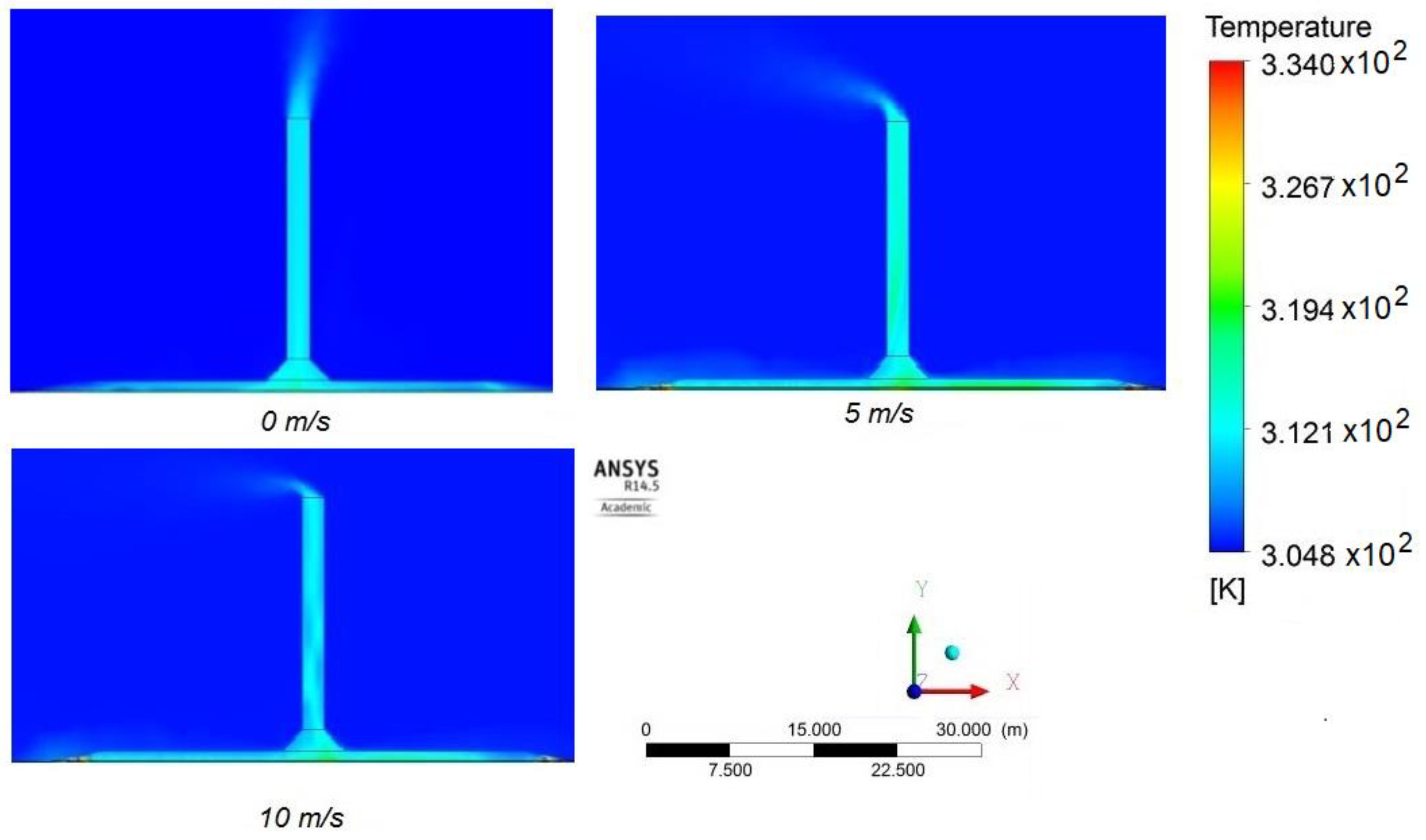
  • The atmosphere was disturbed by the air leaving the tower;
  • The ground temperature decreased with the depth, and ambient temperature was reached at a distance of 0.2 m;
  • The airflow detached from the wall in the connection between the collector and the tower;
  • The crosswind significantly affected the airflow at the outlet of the solar chimney. The airflow was carried by the wind, reducing the velocity at the outlet;
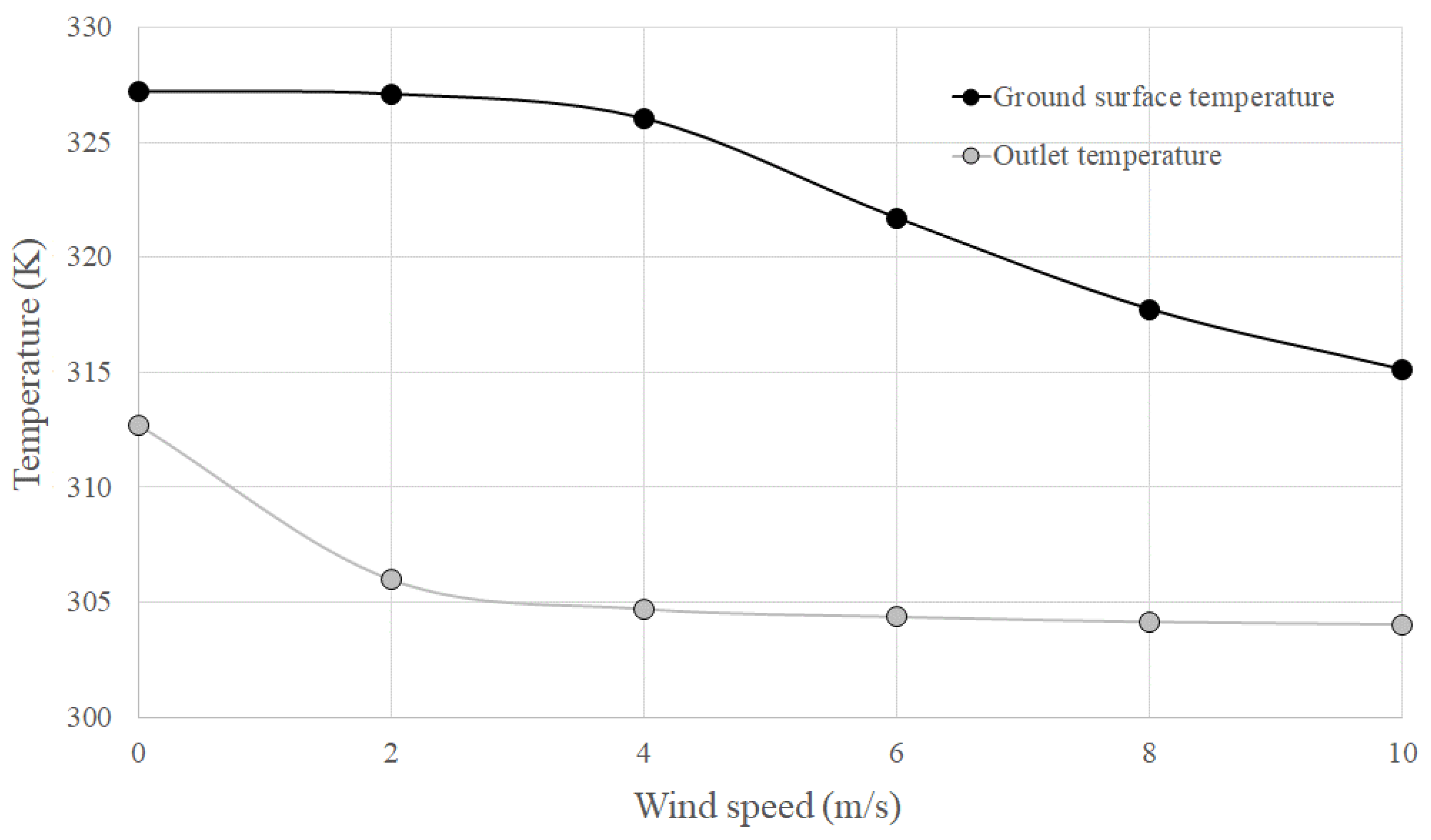
  • The airflow velocity inside the solar chimney increased with the wind speed, decreasing the temperature inside the solar chimney.
The results of this study are presented for steady-state conditions. Future research is recommended to expand the analysis for transient conditions to evaluate the effect of the wind speed combined with the effect of different ambient conditions. It would be also valuable to validate the numerical simulations using experimental data.

Author Contributions

Conceptualization, supervision, funding acquisition, writing, C.B.M.; formal analysis, investigation, J.d.O.C.S. All authors have read and agreed to the published version of the manuscript.

Funding

This research was funded by Fundação de Amparo à Pesquisa do Estado de Minas Gerais (FAPEMIG), grant number PPM-00650-18, Conselho Nacional de Desenvolvimento Científico e Tecnológico (CNPq), grant numbers 444864/2020-2 and 309807/2019-0, Coordenação de Aperfeiçoamento de Pessoal de Nível Superior–Brasil (CAPES)-Finance Code 001, and Pontifícia Universidade Católica de Minas Gerais (PUC Minas), grant number FIP 2017/308-S1.

Institutional Review Board Statement

Not applicable.

Informed Consent Statement

Not applicable.

Data Availability Statement

Not applicable.

Conflicts of Interest

The authors declare no conflict of interest.

References

  1. Assad, M.E.H.; Nazari, M.A.; Rosen, M.A. Applications of renewable energy sources. In Design and Performance Optimization of Renewable Energy Systems; Academic Press: San Diego, CA, USA, 2021; pp. 1–15. [Google Scholar]
  2. Khosravi, A.; Malekan, M.; Pabon, J.J.G.; Assad, M.E.H. Solar power tower system. In Design and Performance Optimization of Renewable Energy Systems; Academic Press: San Diego, CA, USA, 2021; pp. 61–84. [Google Scholar]
  3. Mebarki, A.; Sekhri, A.; Assassi, A.; Hanafi, A.; Marir, B. CFD Analysis of Solar Chimney Power Plant: Finding a Relationship between Model Minimization and Its Performance Use in Urban Areas. SSRN Electron. J. 2021. [Google Scholar] [CrossRef]
  4. Fasel, H.F.; Meng, F.; Shams, E.; Gross, A. CFD analysis for solar chimney power plants. Sol. Energy 2013, 98, 12–22. [Google Scholar] [CrossRef] [Green Version]
  5. Maia, C.B.; Castro Silva, J.D.O. Thermodynamic assessment of a small-scale solar chimney. Renew. Energy 2022, 186, 35–50. [Google Scholar] [CrossRef]
  6. Maia, C.B.; Ferreira, A.G.; Cabezas-Gómez, L.; Castro Silva, J.D.O.; Hanriot, S.D.M. Thermodynamic analysis of the drying process of bananas in a small- scale solar updraft tower in Brazil. Renew. Energy 2017, 114, 1005–1012. [Google Scholar] [CrossRef]
  7. Monghasemi, N.; Vadiee, A. A review of solar chimney integrated systems for space heating and cooling application. Renew. Sustain. Energy Rev. 2018, 81, 2714–2730. [Google Scholar] [CrossRef]
  8. Maghrabie, H.M.; Abdelkareem, M.A.; Elsaid, K.; Sayed, E.T.; Radwan, A.; Rezk, H.; Wilberforce, T.; Abo-Khalil, A.G.; Olabi, A.G. A review of solar chimney for natural ventilation of residential and non-residential buildings. Sustain. Energy Technol. Assess. 2022, 52, 102082. [Google Scholar] [CrossRef]
  9. Maia, C.B.; Silva, F.V.M.; Oliveira, V.L.C.; Kazmerski, L.L. An overview of the use of solar chimneys for desalination Solar desalination. Sol. Energy 2019, 183, 83–95. [Google Scholar] [CrossRef]
  10. Das, P.; Chandramohan, V.P. A review on solar updraft tower plant technology: Thermodynamic analysis, worldwide status, recent advances, major challenges and opportunities. Sustain. Energy Technol. Assess. 2022, 52, 102091. [Google Scholar] [CrossRef]
  11. Maia, C.B.; Ferreira, A.G.; Valle, R.M.; Cortez, M.F.B. Theoretical evaluation of the influence of geometric parameters and materials on the behavior of the airflow in a solar chimney. Comput. Fluids 2009, 38, 625–636. [Google Scholar] [CrossRef]
  12. Schlaich, J. The Solar Chimney: Electricity from the Sun; Edition Axel Menges: Stuttgart, Germany, 2002. [Google Scholar]
  13. Haaf, W.; Friedrich, K.; MAYR†, G.; Schlaich, J. Part I: Principle and Construction of the Pilot Plant in Manzanares. Int. J. Sol. Energy 1983, 2, 3–20. [Google Scholar] [CrossRef]
  14. Haaf, W. Solar Chimneys—Part II: Preliminary Test Results from the Manzanares Pilot Plant. Int. J. Sol. Energy 1984, 2, 141–161. [Google Scholar] [CrossRef]
  15. Maia, C.B.; Ferreira, A.G.; Valle, R.M.; Cortez, M.F.B. Analysis of the Airflow in a Prototype of a Solar Chimney Dryer. Heat Transf. Eng. 2009, 30, 393–399. [Google Scholar] [CrossRef]
  16. Ghalamchi, M.; Kasaeian, A.; Ghalamchi, M.; Mirzahosseini, A.H. An experimental study on the thermal performance of a solar chimney with different dimensional parameters. Renew. Energy 2016, 91, 477–483. [Google Scholar] [CrossRef]
  17. Kasaeian, A.B.; Heidari, E.; Vatan, S.N. Experimental investigation of climatic effects on the efficiency of a solar chimney pilot power plant. Renew. Sustain. Energy Rev. 2011, 15, 5202–5206. [Google Scholar] [CrossRef]
  18. Zhou, X.; Yang, J.; Xiao, B.; Hou, G. Experimental study of temperature field in a solar chimney power setup. Appl. Therm. Eng. 2007, 27, 2044–2050. [Google Scholar] [CrossRef]
  19. Mehrpooya, M.; Shahsavan, M.; Sharifzadeh, M.M.M. Modeling, energy and exergy analysis of solar chimney power plant-Tehran climate data case study. Energy 2016, 115, 257–273. [Google Scholar] [CrossRef]
  20. Maia, C.B.; Castro Silva, J.O.; Cabezas-Gómez, L.; Hanriot, S.M.; Ferreira, A.G. Energy and exergy analysis of the airflow inside a solar chimney. Renew. Sustain. Energy Rev. 2013, 27, 350–361. [Google Scholar] [CrossRef]
  21. Petela, R. Thermodynamic study of a simplified model of the solar chimney power plant. Sol. Energy 2009, 83, 94–107. [Google Scholar] [CrossRef]
  22. Yapıcı, E.Ö.; Ayli, E.; Nsaif, O. Numerical investigation on the performance of a small scale solar chimney power plant for different geometrical parameters. J. Clean. Prod. 2020, 276, 122908. [Google Scholar] [CrossRef]
  23. Fallah, S.H.; Valipour, M.S. Numerical investigation of a small scale sloped solar chimney power plant. Renew. Energy 2022, 183, 1–11. [Google Scholar] [CrossRef]
  24. Cuce, E.; Sen, H.; Cuce, P.M. Numerical performance modelling of solar chimney power plants: Influence of chimney height for a pilot plant in Manzanares, Spain. Sustain. Energy Technol. Assess. 2020, 39, 100704. [Google Scholar] [CrossRef]
  25. Torabi, M.R.; Hosseini, M.; Akbari, O.A.; Afrouzi, H.H.; Toghraie, D.; Kashani, A.; Alizadeh, A. Investigation the performance of solar chimney power plant for improving the efficiency and increasing the outlet power of turbines using computational fluid dynamics. Energy Rep. 2021, 7, 4555–4565. [Google Scholar] [CrossRef]
  26. Pradhan, S.; Chakraborty, R.; Mandal, D.K.; Barman, A.; Bose, P. Design and performance analysis of solar chimney power plant (SCPP): A review. Sustain. Energy Technol. Assess. 2021, 47, 101411. [Google Scholar] [CrossRef]
  27. Kasaeian, A.B.; Molana, S.; Rahmani, K.; Wen, D. A review on solar chimney systems. Renew. Sustain. Energy Rev. 2017, 67, 954–987. [Google Scholar] [CrossRef]
  28. Ming, T.; Wang, X.; De Richter, R.K.; Liu, W.; Wu, T.; Pan, Y. Numerical analysis on the influence of ambient crosswind on the performance of solar updraft power plant system. Renew. Sustain. Energy Rev. 2012, 16, 5567–5583. [Google Scholar] [CrossRef]
  29. Ming, T.; Wang, X.; Gui, J.; De Richter, R.K.; Liu, W.; Xu, G.; Wu, T.; Pan, Y. The influence of ambient crosswind on the performance of solar updraft power plant system. In Solar Chimney Power Plant Generating Technology; Elsevier Inc.: New York, NY, USA, 2016; pp. 163–207. ISBN 9780128092934. [Google Scholar]
  30. Shen, W.; Ming, T.; Ding, Y.; Wu, Y.; de-Richter, R.K. Numerical analysis on an industrial-scaled solar updraft power plant system with ambient crosswind. Renew. Energy 2014, 68, 662–676. [Google Scholar] [CrossRef]
  31. Jafarifar, N.; Behzadi, M.M.; Yaghini, M. The effect of strong ambient winds on the efficiency of solar updraft power towers: A numerical case study for Orkney. Renew. Energy 2019, 136, 937–944. [Google Scholar] [CrossRef]
  32. RahimiLarki, M.; Abardeh, R.H.; Rahimzadeh, H.; Sarlak, H. Performance analysis of a laboratory-scale tilted solar chimney system exposed to ambient crosswind. Renew. Energy 2021, 164, 1156–1170. [Google Scholar] [CrossRef]
  33. Wang, J.; Nie, J.; Jia, J.; Su, H.; Tian, R.; Yan, S.; Gao, H. Structural optimization to reduce the environmental crosswind negative influence on the performance of a solar chimney power plant system. Sol. Energy 2022, 241, 693–711. [Google Scholar] [CrossRef]
  34. Esmail, M.F.C.; Khodary, A.; Mekhail, T.; Hares, E. Effect of wind speed over the chimney on the updraft velocity of a solar chimney power plant: An experimental study. Case Stud. Therm. Eng. 2022, 37, 102265. [Google Scholar] [CrossRef]
  35. Versteeg, H.K.; Malalasekera, W. An Introduction to Computational Fluid Dynamics: The Finite Volume Method; Pearson Education Limited: Upper Saddle River, NJ, USA, 2007; ISBN 9780131274983. [Google Scholar]
  36. Yazdi, M.H.; Solomin, E.; Fudholi, A.; Sopian, K.; Chong, P.L. Numerical analysis of the performance of a hybrid solar chimney system with an integrated external thermal source. Therm. Sci. Eng. Prog. 2021, 26, 101127. [Google Scholar] [CrossRef]
  37. Gholamalizadeh, E.; Kim, M.H. CFD (computational fluid dynamics) analysis of a solar-chimney power plant with inclined collector roof. Energy 2016, 107, 661–667. [Google Scholar] [CrossRef]
  38. Ayadi, A.; Nasraoui, H.; Bouabidi, A.; Driss, Z.; Bsisa, M.; Abid, M.S. Effect of the turbulence model on the simulation of the air flow in a solar chimney. Int. J. Therm. Sci. 2018, 130, 423–434. [Google Scholar] [CrossRef]
  39. Duffie, J.A.; Beckman, W.A. Solar Engineering of Thermal Processes: Fourth Edition; John Wiley & Sons: New York, NY, USA, 2013; ISBN 9780470873663. [Google Scholar]
  40. Pretorius, J.P. Optimization and Control of a Large-Scale Solar Chimney Power Plant. Ph.D. Thesis, University of Stellenbosch, Stellenbosch, South Africa, 2007. [Google Scholar]
  41. Li, J.Y.; Guo, P.H.; Wang, Y. Effects of collector radius and chimney height on power output of a solar chimney power plant with turbines. Renew. Energy 2012, 47, 21–28. [Google Scholar] [CrossRef]
  42. Menter, F.R.; Hemstrom, B.; Henriksson, M.; Karlsson, R.; Latrobe, A.; Martin, A.; Muhlbauer, P.; Scheuerer, M.; Smith, B.; Takacs, T.; et al. CFD Best Practice Guidelines for CFD Code Validation for Reactor-Safety Applications; Evol-Ecora-D 01; European Commission: Brussels, Belgium, 2002.
  43. White, F.M.; Ng, C.O.; Saimek, S. Fluid Mechanics; McGraw-Hill Series in Mechanical Engineering; McGraw-Hill: New York, NY, USA, 2011; ISBN 9780071311212. [Google Scholar]
  44. Lupi, F.; Borri, C.; Harte, R.; Krätzig, W.B.; Niemann, H.J. Facing technological challenges of Solar Updraft Power Plants. J. Sound Vib. 2015, 334, 57–84. [Google Scholar] [CrossRef]
  45. Harte, R.; Höffer, R.; Krätzig, W.B.; Mark, P.; Niemann, H.J. Solar updraft power plants: Engineering structures for sustainable energy generation. Eng. Struct. 2013, 56, 1698–1706. [Google Scholar] [CrossRef]
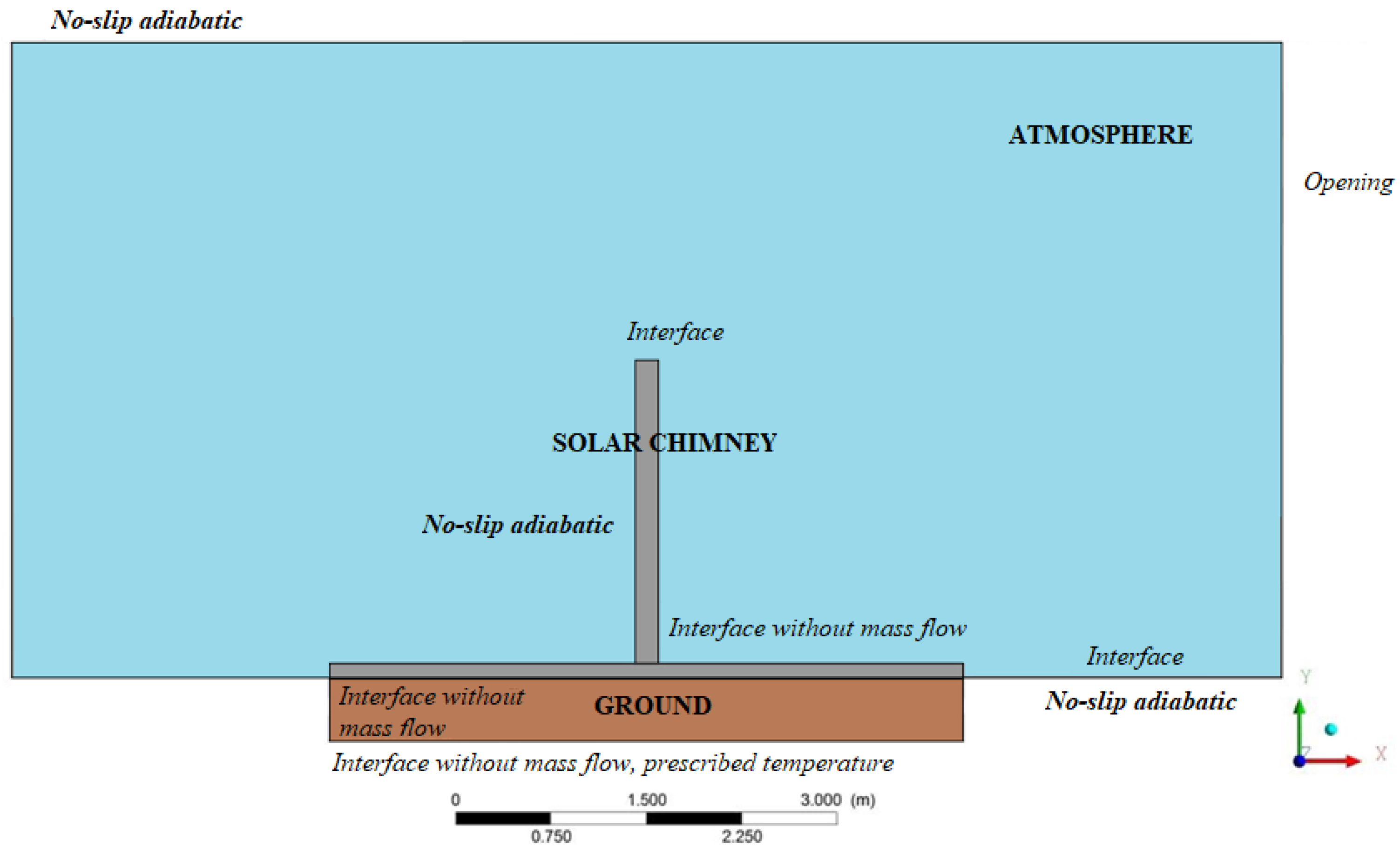
Figure 1. Energy balance.
Sustainability 14 15208 g001
Figure 2. Computational domain.
Sustainability 14 15208 g002
Figure 3. Boundary conditions.
Sustainability 14 15208 g003
Figure 4. Temperature distribution in the computational domain.
Sustainability 14 15208 g004
Figure 5. Temperature profile in a cross-section area of the tower.
Sustainability 14 15208 g005
Figure 6. Temperature distribution in the tower.
Sustainability 14 15208 g006
Figure 7. Ground temperature distribution.
Sustainability 14 15208 g007
Figure 8. Velocity distribution inside the solar chimney.
Sustainability 14 15208 g008
Figure 9. Streamlines inside the solar chimney.
Sustainability 14 15208 g009
Figure 10. Velocity profile in a cross-section area of the tower.
Sustainability 14 15208 g010
Figure 11. Velocity distribution in the tower.
Sustainability 14 15208 g011
Figure 12. Shear stress distribution in the tower wall.
Sustainability 14 15208 g012
Figure 13. Air velocity for different wind speeds.
Sustainability 14 15208 g013
Figure 14. Air temperature for different wind speeds.
Sustainability 14 15208 g014
Figure 15. Velocity distribution in the tower for different wind speeds.
Sustainability 14 15208 g015
Figure 16. Influence of the wind speed on the outlet velocity and mass flow rate.
Sustainability 14 15208 g016
Figure 17. Influence of the wind speed on the outlet airflow and ground surface temperatures.
Sustainability 14 15208 g017
Table 1. Boundary conditions.
RegionBoundary Condition
Atmosphere–upper and bottom regionsNo slip, adiabatic
Atmosphere–lateralOpening, one face with prescribed velocity
Ground–bottom regionNo slip, prescribed temperature
Ground–upper regionInterface without mass flow, prescribed heat flux
Ground–lateralNo slip, adiabatic
Solar collector–lateralOpening, prescribed ambient temperature
Solar collector–upper surfaceInterface without mass flow
Tower wallNo slip, adiabatic
Tower outletOpening
Publisher’s Note: MDPI stays neutral with regard to jurisdictional claims in published maps and institutional affiliations.

