
Ionic Mass Transfer at Point Electrodes Located at Cathode Support Plate in an Electrorefining Cell in Presence of Rectangular Turbulent Promoters

 and
and
Abstract
:1. Introduction
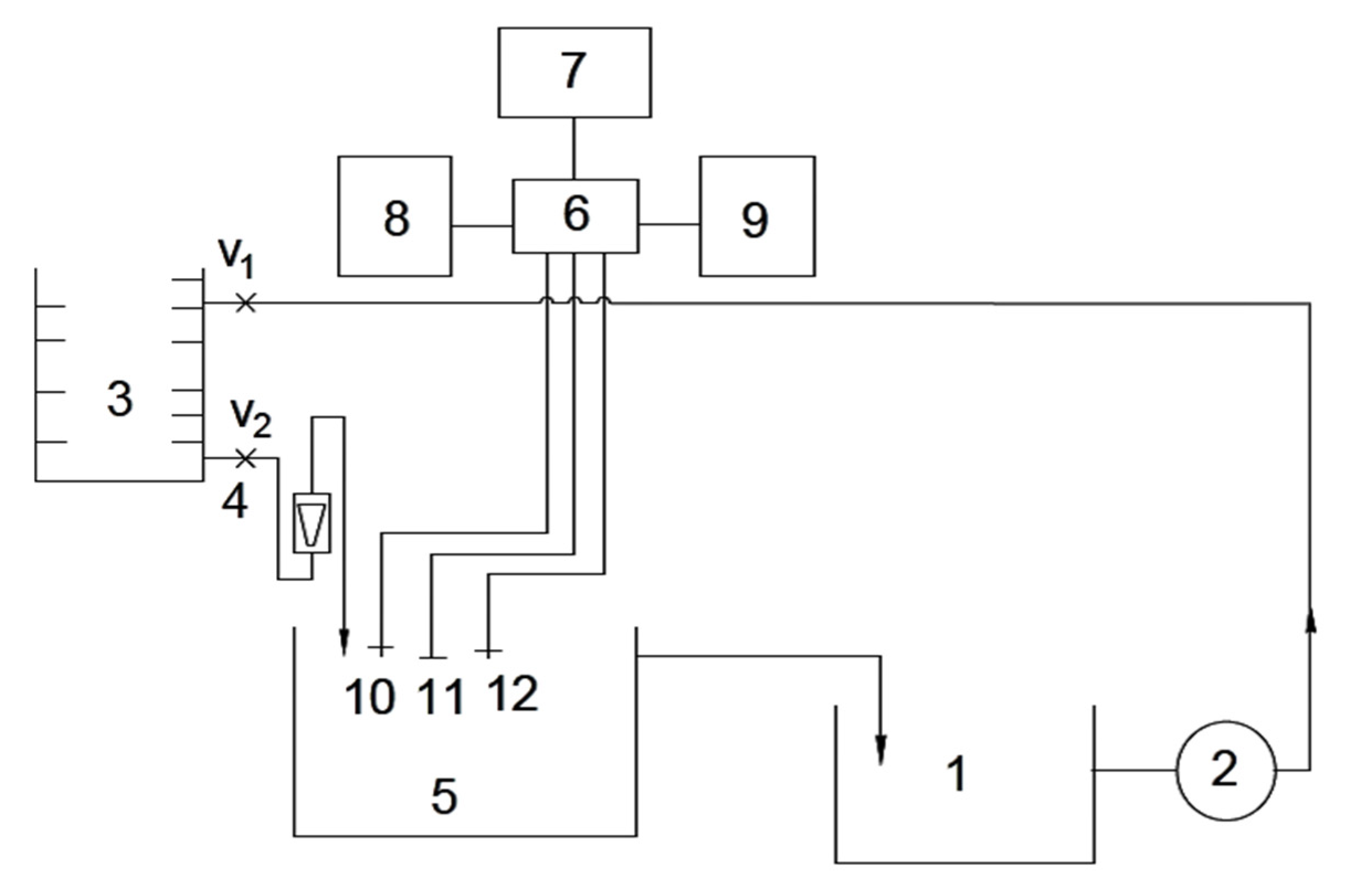
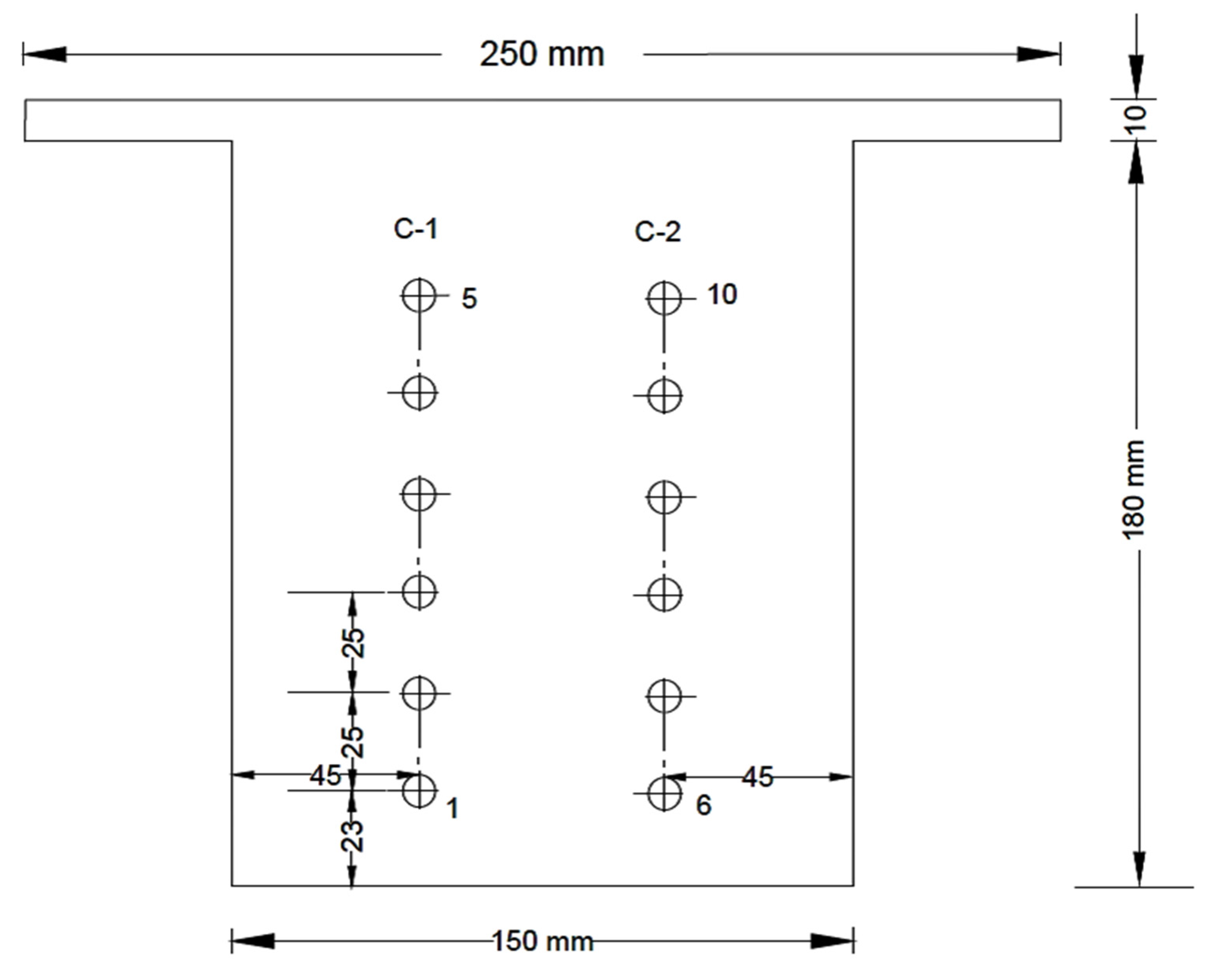
2. Experimental
3. Results and Discussion
- (i)
- Ripple flow-induced due to promoters;
- (ii)
- Crossflow due to working/counter electrode plate; and
- (iii)
- Slit flow caused due to narrow gap between the cathode support plate and cell wall.
- (a)
- Electrolyte flow rate (Q);
- (b)
- Promoter height (H); and
- (c)
- Distance between the promoters (S).
- K= mass transfer coefficient m/s;
- IL = limiting current density;
- C = concentration of the reacting ion, k·mol/m3;
- A = area of the electrode, m2;
- F = Faraday’s constant, 96,500 coulombs/mol.; and
- n = number of electrons taking place in the reaction
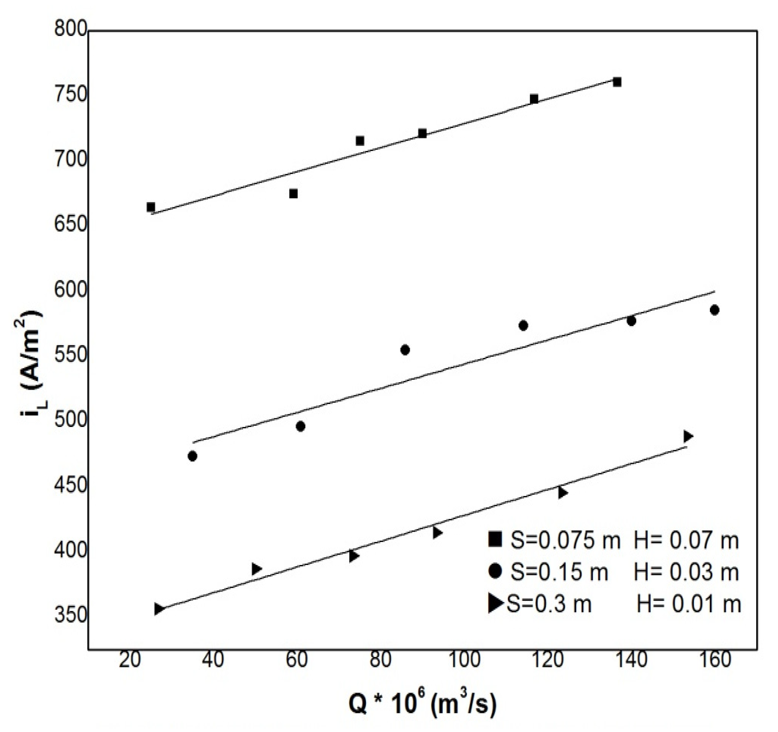
3.1. Effect of Flow Rate
- KL = overall mass transfer coefficient, m/s;
- V = velocity of the electrolyte based on the equivalent diameter of the cell, m/s.
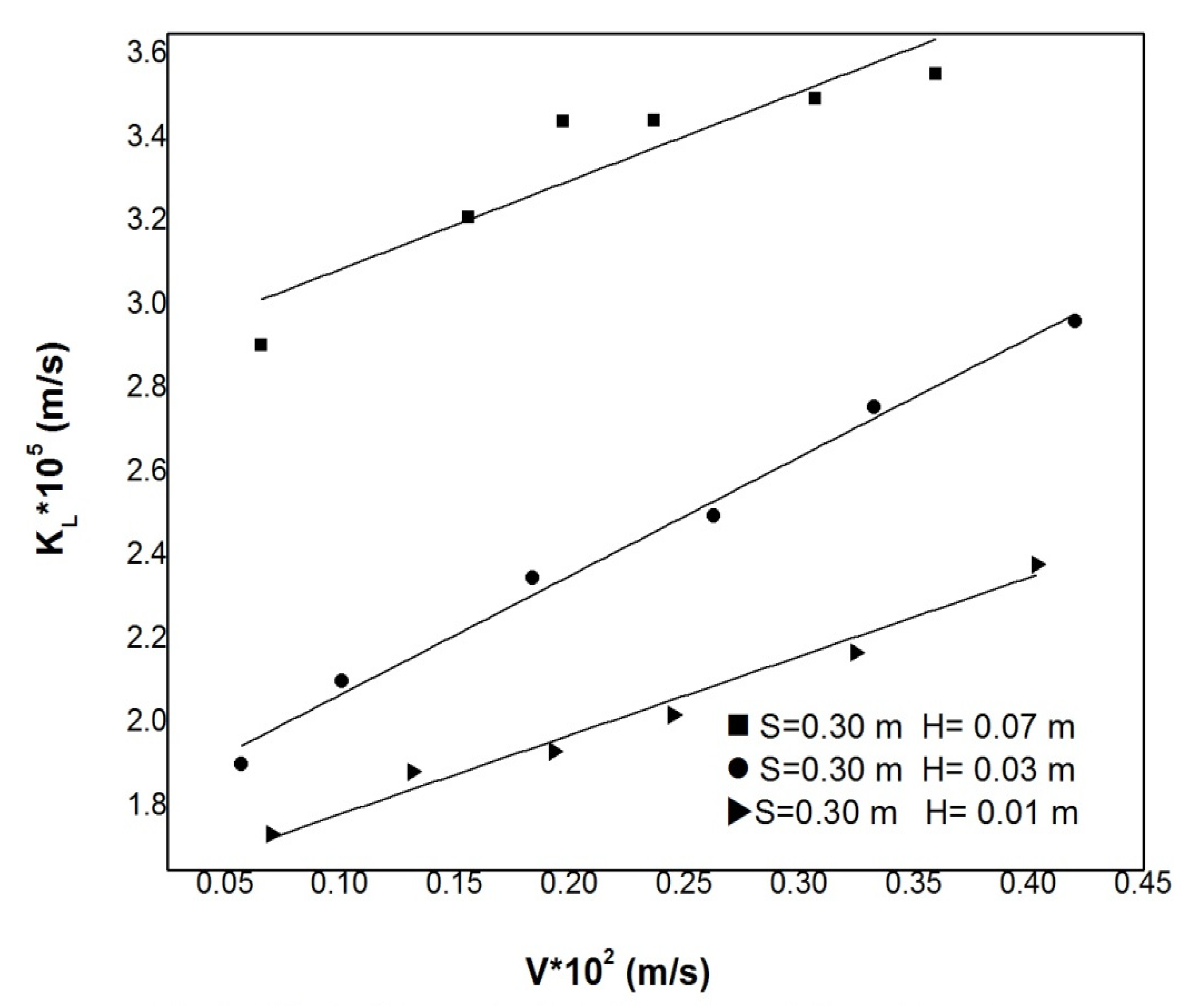
3.2. Effect of Promoter Height
3.3. Effect of Promoter Spacing
4. Conclusions
Author Contributions
Funding
Institutional Review Board Statement
Informed Consent Statement
Data Availability Statement
Acknowledgments
Conflicts of Interest
Nomenclature
| A | area of the electrode, m2 |
| CO | concentration of the reacting ion, kmol/m3 |
| De | equivalent diameter of the electrolytic cell, 4 Wh/(W + 2 h), m |
| DL | diffusivity, m/s |
| F | Faraday, 96,500 Coulombs/equivalent |
| h | height of the electrolyte in the cell, m |
| H | height of the promoter, m |
| I | limiting current, A |
| IL | limiting current density, A/m2 |
| KL | overall mass transfer coefficient, m/s |
| Q | flow rate, m3/s |
| S | spacing of the promoter, m |
| V | velocity of the electrolyte based on the equivalent diameter of the cell. |
| W | width of the electrolytic cell, m |
| p | density of the electrolyte, Kg/m3 |
| n | number of electrons taking place in the reaction |
References
- Storck, A.; Coeuret, F. Mass and momentum transfer at a wall in the presence of turbulence promoters. Electrochim. Acta 1977, 22, 1155–1160. [Google Scholar] [CrossRef]
- Rai, V.; Liu, D.; Xia, D.; Jayaraman, Y.; Gabriel, J.-C.P. Electrochemical approaches for the recovery of metals from electronic waste: A critical review. Recycling 2021, 6, 53. [Google Scholar] [CrossRef]
- Minakshi, M.; Mitchell, D.R.G.; Prince, K. Incorporation of TiB2 additive into MnO2 cathode and its influence on rechargeability in an aqueous battery system. Solid State Ionics 2008, 179, 355–361. [Google Scholar] [CrossRef]
- Minakshi, M.; Mitchell, D.R.G.; Munnangi, A.R.; Barlow, A.J.; Fichtner, M. New insights into the electrochemistry of magnesium molybdate hierarchical architectures for high performance sodium devices. Nanoscale 2018, 10, 13277–13288. [Google Scholar] [CrossRef] [Green Version]
- Chandra, A.; Pathiwada, D.; Chattopadhyay, S. COMSOL simulation and experimental validation of promoter geometries facilitating citric acid transport in electrodialysis. Chem. Eng. Res. Des. 2019, 142, 386–411. [Google Scholar] [CrossRef]
- Gangadhar, M.; Srikanth, R.; Rao, V.N. Ionic mass transfer studies at the wall of cylindrical vessel with groove twisted tape promoters. Int. J. Mech. Eng. Technol. 2018, 9, 329–339. [Google Scholar]
- Rao, D.S.; Venkateshwarlu, P. Ionic mass transfer studies in an open cell in the presence of circular cylindrical promoter. Chem. Eng. Processing Process Intensif. 2004, 43, 35–41. [Google Scholar]
- Leitz, F.B.; Marincic, L. Enhanced mass transfer in electrochemical cells using turbulence promoters. J. Appl. Electrochem. 1977, 7, 473–484. [Google Scholar] [CrossRef]
- Blum, H.A.; Oliver, L.R. Heat Transfer in a Decaying Vortex System, American Society of Mechanical Engineers; ASME: New York, NY, USA, 1966. [Google Scholar]
- Gambill, W.R.; Greene, N.D. Boiling burnout with the water-vortex flow. Chem. Eng. Prog. Symp. Ser. 1958, 54, 68–76. [Google Scholar]
- Nieva, I.A.; Bohm, U. Local mass transfer for crossflow through tube banks: Equilateral triangular layout at intermediate Reynolds numbers. Int. Commun. Heat Mass Transf. 1985, 12, 277–285. [Google Scholar] [CrossRef]
- Krishna, P.G. Ionic mass transfer in presence of turbulence promoters in a circular conduit. Int. Commun. Heat Mass Transfer 2001, 28, 499–508. [Google Scholar] [CrossRef]
- Venkateswarlu, P. Studies on Ionic Mass Transfer with Coaxially Placed Discs on a Rod as Turbulence Promoters. Ph.D. Thesis, Andhra University, Visakhapatnam, India, 1987. [Google Scholar]
- Kim, D.H.; Chang, H.N. Experimental study of mass transfer around a turbulence promoter by the limiting current method. Int. J. Heat Mass Transf. 1983, 26, 1007–1016. [Google Scholar] [CrossRef]
- Sedahmed, G.H.; Shemilt, L.W. Natural convection mass transfer at cylinders in different positions. Chem. Eng. Sci. 1982, 37, 159–166. [Google Scholar] [CrossRef]
- Storck, A.; Hutin, D. Improvement of copper recovery in electrochemical reactors using turbulence promoters. Electrochim. Acta 1981, 26, 117–125. [Google Scholar] [CrossRef]
- Subbaiah, T.; Venkateswarlu, P.; Das, R.P.; Raju, G.J.V.J. Mass transfer conditions at a cathode support plate in an electrochemical cell. Chem. Eng. Processing Process Intensif. 1995, 34, 495–501. [Google Scholar] [CrossRef]
- Subbaiah, T.; Venkateswarlu, P.; Das, R.P.; Raju, G.J.V.J. Improved ionic mass transfer in an electrochemical cell in presence of turbulence promoters. Hydrometallurgy 1996, 42, 93–102. [Google Scholar] [CrossRef]
- Sammera, S.; Kavitha, G.; Babu, N.C. Studies on ionic mass transfer in an electrolytic cell in the presence of semicircular teethed promoters. Int. J. Eng. Sci. Res. Technol. 2016, 5, 257–271. [Google Scholar]
- Kharicha, A.; Karimi-Sibaki, E.; Vakhrushev, A.; Wu, M.; Ludwig, A.; Bohacek, J. Hydrodynamically enhanced electrochemical mass transfer of the surface of an electrolytic conductive droplet. Heat Mass Transf. 2021, 57, 1697–1705. [Google Scholar] [CrossRef]
- Perez-Gallent, E.; Sanchez-Martinez, C.; Geers, L.F.G.; Turk, S.; Latsuzbaia, R.; Goetheer, E.L.V. Overcoming mass transport limitations in electrochemical reactors with a pulsating flow electrolyser. Ind. Eng. Chem. Res. 2020, 59, 5648–5656. [Google Scholar] [CrossRef]
- Kubannek, F.; Krewer, U. Studying the interaction of mass transport and electrochemical reaction kinetics by species frequency response analysis. J. Electrochem. Soc. 2020, 167, 144510. [Google Scholar] [CrossRef]
- Walker, W.S.; Cavalcanti, E.B.; Atrashkevich, A.; Fajardo, A.S.; Brillas, E.; Segura, S.G. Mass transfer residence time distribution in an electrochemical cell with air diffusion electrode-effect of air pressure and mesh promoters. Electrochim. Acta 2021, 378, 138131. [Google Scholar] [CrossRef]
- Chandralekha, N.; Tukarambai, M.; Chitti Babu, N.; Rao, V.N. Efficacy of mass transfer coefficient: Multiple pentagonal plate assembly. Mater. Today Proc. 2021, in press. [Google Scholar] [CrossRef]
- Rao, S.S. Studies on Ionic Mass Transfer with Coaxially Placed Cones on a Rod in Homogeneous Fluid and Fluidized Beds. Ph.D. Thesis, Andhra University, Visakhapatnam, India, 1983. [Google Scholar]
- Dudukovic, A.P.; Djurdjevic, S.K.K. Effect of an array of objects on mass transfer rates to the tube wall: An additional note. AIChE J. 1980, 26, 299–301. [Google Scholar] [CrossRef]
- Ravi, T.; Rao, B.S.; Krishna, P.G.; Venkateswarlu, P. Ionic mass transfer studies in fluidized beds with coaxially placed discs on a rod as internal. Chem. Eng. Processing Process Intensif. 1996, 35, 187–193. [Google Scholar] [CrossRef]


| (a) | ||
| V × 102 m/s | KL × 105 m/s | |
| 1 | 0.0658 | 3.1338 |
| 2 | 0.1559 | 3.1819 |
| 3 | 0.1973 | 3.3733 |
| 4 | 0.2368 | 3.3993 |
| 5 | 0.3070 | 3.5253 |
| 6 | 0.3596 | 3.5870 |
| (b) | ||
| V × 102 m/s | KL × 105 m/s | |
| 1 | 0.0702 | 1.7357 |
| 2 | 0.1316 | 1.8848 |
| 3 | 0.1930 | 1.9335 |
| 4 | 0.2450 | 2.0206 |
| 5 | 0.3245 | 2.1697 |
| 6 | 0.4034 | 2.3806 |
| (c) | ||
| V × 102 m/s | KL × 105 m/s | |
| 1 | 0.0921 | 2.3604 |
| 2 | 0.1600 | 2.4762 |
| 3 | 0.2256 | 2.7680 |
| 4 | 0.3000 | 2.8607 |
| 5 | 0.3678 | 2.8782 |
| 6 | 0.4203 | 2.9216 |
Publisher’s Note: MDPI stays neutral with regard to jurisdictional claims in published maps and institutional affiliations. |
© 2022 by the authors. Licensee MDPI, Basel, Switzerland. This article is an open access article distributed under the terms and conditions of the Creative Commons Attribution (CC BY) license (https://creativecommons.org/licenses/by/4.0/).
Share and Cite
Subbaiah, T.; Vijetha, P.; Marandi, B.; Sanjay, K.; Minakshi, M. Ionic Mass Transfer at Point Electrodes Located at Cathode Support Plate in an Electrorefining Cell in Presence of Rectangular Turbulent Promoters. Sustainability 2022, 14, 880. https://doi.org/10.3390/su14020880
Subbaiah T, Vijetha P, Marandi B, Sanjay K, Minakshi M. Ionic Mass Transfer at Point Electrodes Located at Cathode Support Plate in an Electrorefining Cell in Presence of Rectangular Turbulent Promoters. Sustainability. 2022; 14(2):880. https://doi.org/10.3390/su14020880
Chicago/Turabian StyleSubbaiah, Tondepu, Ponnam Vijetha, Barsha Marandi, Kali Sanjay, and Manickam Minakshi. 2022. "Ionic Mass Transfer at Point Electrodes Located at Cathode Support Plate in an Electrorefining Cell in Presence of Rectangular Turbulent Promoters" Sustainability 14, no. 2: 880. https://doi.org/10.3390/su14020880