Article

Design and Performance Analysis of Hybrid Battery and Ultracapacitor Energy Storage System for Electrical Vehicle Active Power Management

by
Aditya Kachhwaha
1,
Ghamgeen Izat Rashed
2,*,
Akhil Ranjan Garg
1,
Om Prakash Mahela
3,
Baseem Khan
4,
Muhammed Badeaa Shafik
5 and
Mohamed G. Hussien
6,*
1
Department of Electrical Engineering, Faculty of Engineering and Architecture, Jai Narain Vyas University, Jodhpur 342011, India
2
School of Electrical Engineering and Automation, Wuhan University, Wuhan 430072, China
3
Assistant Engineer, Power System Planning Division, Rajasthan Rajya Vidyut Prasaran Nigam Ltd., Jaipur 302005, India
4
Department of Electrical and Computer Engineering, Hawassa University, Hawassa P.O. Box 5, Ethiopia
5
Electric Power System and Machines Department, Faculty of Engineering, Kafrelsheikh University, Kafrelsheikh 33516, Egypt
6
Department of Electrical Power and Machines Engineering, Faculty of Engineering, Tanta University, Tanta 31527, Egypt
*
Authors to whom correspondence should be addressed.
Sustainability 2022, 14(2), 776; https://doi.org/10.3390/su14020776
Submission received: 13 September 2021 / Revised: 26 October 2021 / Accepted: 27 October 2021 / Published: 11 January 2022
(This article belongs to the Special Issue Smart and Sustainable EV Charging Infrastructure)

Abstract

:
The electrical energy storage system faces numerous obstacles as green energy usage rises. The demand for electric vehicles (EVs) is growing in tandem with the technological advance of EV range on a single charge. To tackle the low-range EV problem, an effective electrical energy storage device is necessary. Traditionally, electric vehicles have been powered by a single source of power, which is insufficient to handle the EV’s dynamic demand. As a result, a unique storage medium is necessary to meet the EV load characteristics of high-energy density and high-power density. This EV storage system is made up of two complementing sources: chemical batteries and ultracapacitors/supercapacitors. The benefits of using ultracapacitors in a hybrid energy storage system (HESS) to meet the low-power electric car dynamic load are explored in this study. In this paper, a HESS technique for regulating the active power of low-powered EV simulations was tested in a MATLAB/Simulink environment with various dynamic loading situations. The feature of this design, as noted from the simulation results, is that it efficiently regulates the DC link voltage of an EV with a hybrid source while putting minimal load stress on the battery, resulting in longer battery life, lower costs, and increased vehicle range.

1. Introduction

Electric cars (EVs) are becoming more popular as a result of environmental concerns and rising gasoline prices. When compared to gasoline-based internal combustion engine (ICE) vehicles, EVs have superior fuel economy and adhere to modern world pollution requirements. Standard EVs are available on the market as a power source. It is worth noting that EVs are subjected to a variety of time-varying power needs, such as abrupt acceleration and deceleration (regeneration period). This acceleration and regeneration period is analogous to pulse load changes, and the battery must absorb a huge transient charging current at this time, negatively impacting the battery’s performance. A supplementary energy storage technology (ultracapacitor) is occasionally used to mitigate this negative effect on the battery [1].
By incorporating diverse topologies of ultracapacitor connection, the influence of the battery’s performance on abrupt charging and draining can be mitigated. An ultracapacitor can handle an instantaneous impulse EV load since it is a high-power density device, which decreases the stress on the battery and raises the high-rate current demand. The combination of a battery and an ultracapacitor allows us to meet peak power demand for a short period of time with the ultracapacitor and average power demand for a long period of time with the battery [2,3]. Ultracapacitors have the advantage of being able to deliver and even absorb huge transient pulse power, ensuring that the load’s requirements are met during the drive’s abrupt acceleration and deceleration/regenerative periods. Because the battery and ultracapacitor have different basic characteristics (for example, voltage levels or charging/discharging), an adequate interface between both sources is essential. Multiple types of energy storage, such as batteries and ultracapacitors, can improve the overall performance of EVs by providing higher-power density, energy density, and life cycle. In addition, the improved Hybrid Energy Storage System (HESS) between these devices will reduce energy utilization and extend battery life [4]. To meet the dynamic EV demand, our active HESS allows ultracapacitors and batteries to use their maximum capacity [4,5]. An active HESS arrangement makes the most of the available ultracapacitors energy, resulting in enhanced fuel economy and energy security due to the usage of various sources.
Charging, discharging, voltage level, and other basic features of the hybrid source (ultracapacitor and battery) are not equal, and a suitable interface is necessary. Because a bidirectional DC-DC converter can meet the requirements for high utilization efficiencies, a real-time EV energy storage management strategy (known as HESS) is required for a better and more effective allocation of power demand for the vehicular system between energy storage devices [1,6]. Active power management always uses a single control variable and a single control state (source state-of-charge, source power level). As a result, adding an ultracapacitor to the system introduces another control variable with a state of a degree of freedom. The design and optimization of active power management are complicated by this additional state [7].
This hybridization of battery and ultracapacitor protects the battery and also optimizes the size of both energy storage systems using the different HESS management schemes, which further reduces the overall cost [8]. Many HESS management schemes, such as the fuzzy-logic control scheme [9], the rule-based control scheme [10], the model-predictive control scheme [11], and the filtration-based scheme [12] etc., are introduced over time. Hung et al. [13] proposed an optimization scheme that involved the sizing of a hybrid source with an energy storage management strategy to achieve high performance of an EV with minimum operating costs. Both the constraints of sizing and the power management of an EV must be controlled simultaneously, as the individual system contains different components, which can be incorporated using a rule-based HESS technique [7,14].
The combined use of several energy storage systems in an EV allows the system to harness diverse sources at different times to efficiently drive the system [7,15]. On the basis of diverse load profiles, such as constant frequency, variable frequency pulsing load, and the typical WLTC Class 1 (a small, low-powered EV) drive cycle, this research examines the performance of rule-based HESS active power-sharing amongst hybrid sources [16,17,18,19,20,21,22,23,24,25,26]. The proposed HESS system is tested using this standard real drive, in conjunction with the EV dynamic model, to generate a small-scale EV load profile. The system is then subjected to the obtained load profile, and the simulation results are evaluated in the MATLAB/Simulink environment. Numerous variants of a rule-based active HESS scheme were used in this study, successfully reducing the constraint of a single power source (limited energy density and power density).

2. Proposed Electrical Vehicle Model

The key parameter of analysis is a rule-based active HESS, which subjects the system to the real drive equivalent of instantaneous power demand. This can be obtained by implementing the dynamic modeling approach, which is based on the power-torque equation shown in Figure 1. The EV system dynamic input parameters are shown in Table 1. Acceleration force, aerodynamic drag force, rolling resistance force and gravitational force are the main components. Their summation is known as the total traction force (FT), which is applied to the EV drive wheels that vary instantaneously, according to the drive cycle [7,15] (here, WLTC Class 1 is used [16]).
The force corresponding to rolling friction resistance, which is caused by the action between EV wheels and a road surface, is represented by the following Equation (1). The rolling resistance force is directly proportional to the vehicle weight and, from Equation (1), C R = rolling coefficient that presents the roughness factor of a surface. W E V = Weight of EV.
F R o l l i n g = W E V × C R
The grade resistance force is a type of gravitational force that acts in the opposite direction to the EV motion when running on an inclined surface. The grading resistance force of an EV during the drive cycle inclined motion can be obtained by Equation (2). The surface angle Ɵ has a high inclination here [27].
F G R F = W E V × sin Ɵ
The force related to the EV drive torque is directly related to the acceleration of the vehicle. The acceleration force forces the vehicle to reach its nominal speed within the time limit specified. The acceleration force is given by Equation (3). Here, a denotes acceleration and m denotes the EV’s mass [7].
F a = m × a
The aerodynamic drag phenomenon increases resistance during a higher speed of an EV, represented as vehicle speed function in Equation (4). Here v = EV speed, p = air density, C D = drag coefficient and A r e a F = vehicle frontal area.
F A D R = 1 2 × p × v 2 × C D × A r e a F
The total EV tractive force can be obtained by Equations (1)–(4), as shown in Equation (5). It is the summation of all kinds of forces acting on the EV during the drive cycle run [27].
F T = F R o l l i n g + F G R F + F a + F A D R
The standard WLTC Class 1 city drive cycle for low-power EVs is shown in Figure 2. This drive cycle with the vehicle dynamic model is used to obtain the total instantaneous power required for the EV wheels. The all-corresponding vehicle dynamic model waveforms are shown in Figure 2. The total EV dynamic load is calculated by the EV dynamic model, as shown in Figure 3; it is scaled-down to test the load current profile of a WLTC Class 1 with an active power HESS scheme [7,27].

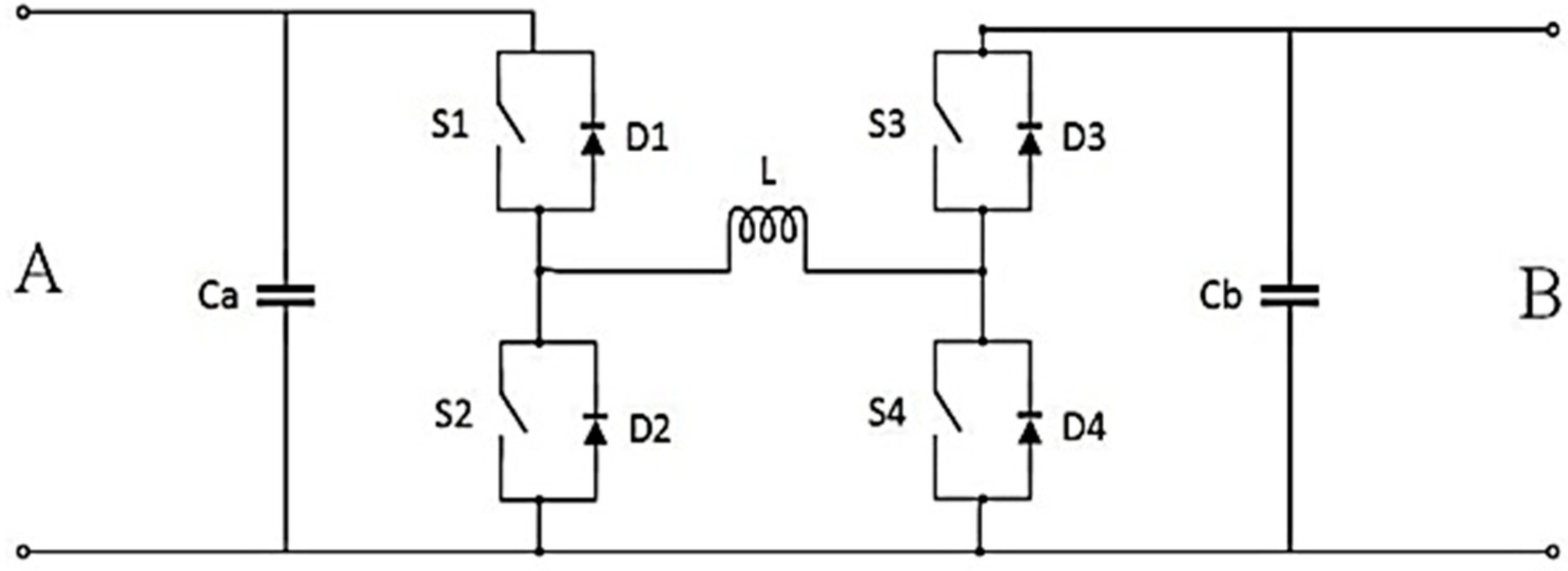
3. HESS System Configurations

HESS can be defined on the basis of the connection of the storage unit to the DC link of the EV. HESS system configurations are passive, semi-active and active. There is no connected converter between the energy storage unit and the DC link in a passive HESS configuration. In a semi-active HESS configuration, only one energy storage unit is connected to the DC link via a DC-DC converter; the other storage unit is connected directly. In most cases, the battery is connected directly to this configuration. The configuration in which the energy storage is connected to the DC link, having a bidirectional DC-DC converter between them, is known as an active HESS configuration [7,28,29,30]. Figure 4 depicts a block diagram of HESS with DC-DC converters linked to a DC bus modulated by the HESS controller.

Active HESS Configurations

Both sources are depicted as DC-DC bidirectional converters between DCs in the EV system block diagram in Figure 4. The storage system comprises the converter working in the current control mode, whereas the ultracapacitor DC-DC converter is controlled by a sliding mode control (SMC) algorithm [31,32,33]. The power splitting of the hybrid source is implemented by the rule-based, active power HESS system. The proposed system contains the Li-ion battery bank and ultracapacitor hybrid source for low-power EV testing under the WLTC Class 1 drive load, governed by the active HESS scheme [7].
Hybrid sources have the capability to meet instantaneous load fluctuations effectively. Table 2 shows the parameters of a small, low-power EV HESS system. The system is loaded with the WLTC Class 1 current load profile, calculated by the vehicle dynamic model. Alongside this, the EV HESS system is subjected to a constant and varying frequency pulse load. The active HESS controller scheme is represented in Figure 5.
The active rule-based HESS algorithm is implemented for the efficient distribution of active power between the battery and ultracapacitor while keeping the base load across the battery. The base load is calculated and fed back to the current-mode control (CMC) converter of the battery as a battery reference current (IB_Ref). This is compared again to the battery CMC control block, where the control action is carried out by the battery source current control, with the help of an optimal-tuning PID controller [31,34,35]. The load across the battery changes according to the load fluctuations from one level to another in this rule-based HESS scheme. If it goes to another level, the reference battery current is changed to some extent, and other rapid fluctuations are handled by the eliminator with its control signal. Active power splitting changes during the drive cycle and depends on the state of charge (SOC) battery, SOC ultracapacitor, hybrid sources, output currents, and load current. The scheme works effectively with hybrid sources by reducing and increasing the battery reference current when the drive cycle load demand goes to a lower level and when the drive is running at its maximum speed, respectively. The connection of different sources in hybrid sources to the DC link is also subject to their SOC level.

4. Performance of Ultracapacitor-Battery Hybrid Source

The hybrid ultracapacitor-battery source can alleviate the rate of change of high pulsed EV loads. The whole EV system, with the HESS controller and hybrid source connected with a bidirectional DC-DC converter, is shown in Figure 6.
The battery DC-DC converter current control scheme and ultracapacitor SMC control have an outer loop for load voltage control and an inner loop for limiting the inductor current deviation, as shown in Figure 7a,b, respectively. The 4-quadrant chopper (4QC) topology is selected for effective bidirectional ultracapacitor output voltage regulation, as shown in Figure 8. The 2-quadrant (2QC) chopper topology is selected for battery converter action, as the battery has to supply power in different constant current modes throughout the WLTC Class 1 drive load profile [7,36,37,38].

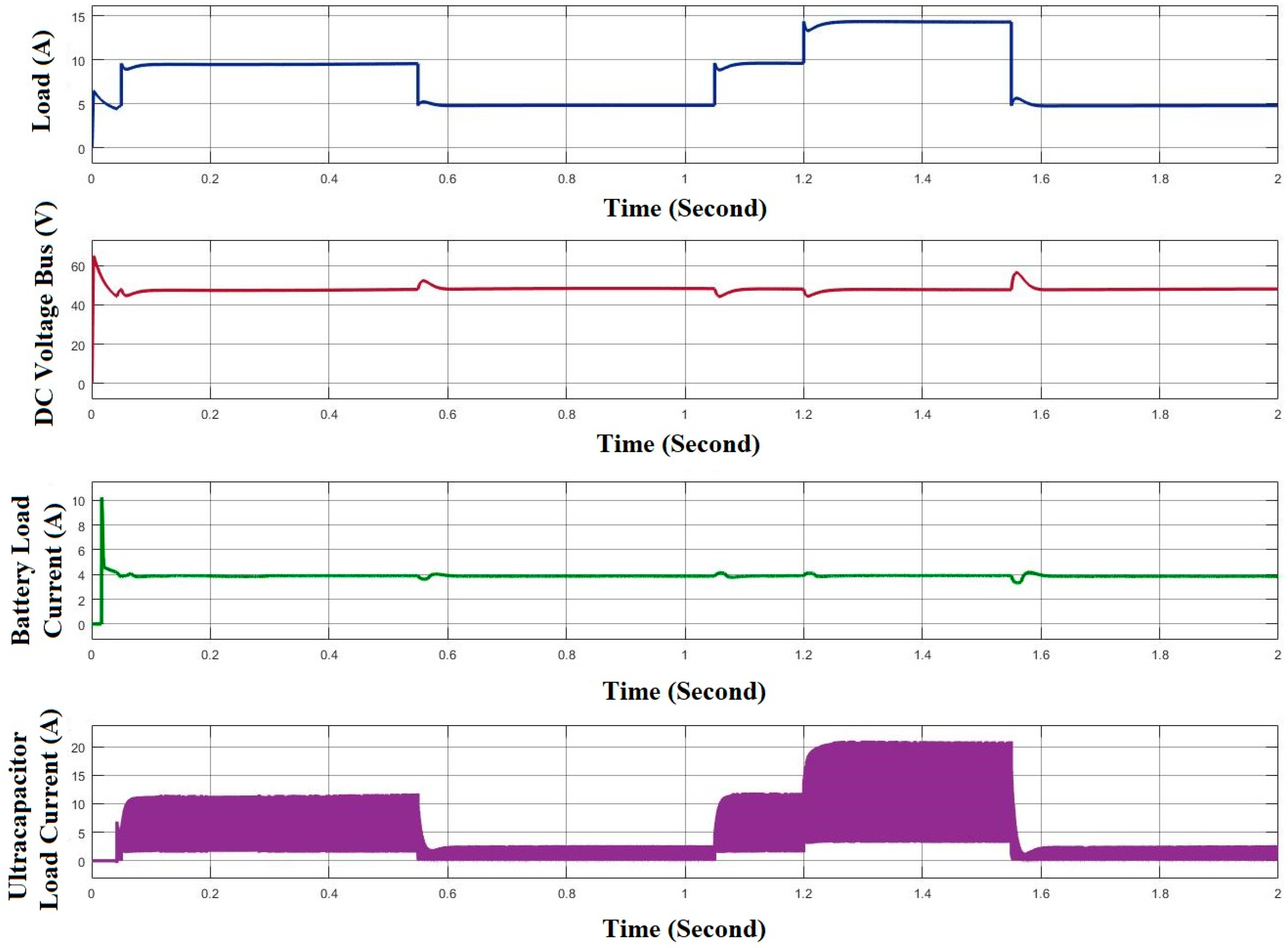
5. Simulation Results and Analysis

The operation of an EV during a drive cycle has different modes, such as a constant speed mode, a decelerating mode, and an accelerating mode. The basic understanding of the hybrid source is that the battery must supply the maximum power during constant speed mode, whereas the ultracapacitor converter action supplies the related pulse load during other acceleration/deceleration periods [7,31,39]. The study was carried out by testing the EV system with different loading modes, as discussed below.

5.1. Mode 1

In this mode, the EV HESS system is subjected to a constant frequency pulsating load, having a lower level of 20 A and a higher level of 45 A, as shown in the load waveform in Figure 9.
A major finding from this mode is the active HESS scheme effectiveness with hybrid source performance [7,40]. The battery reference current is set as the lower limit of the pulse load; the fluctuations from this level are handled by the ultracapacitor converter action, as represented by an ultracapacitor current waveform in Figure 9. In the normal operation of this drive, the average load is set to be supplied by the battery as it is a high-energy density device, shown in Figure 9. Deviations from this set value are from other high-power density devices, which will eventually enhance the life and reduce the battery rating, compared to the same energy storage system (ESS) EV rating [31,41].

5.2. Mode 2

As shown in Figure 10, this mode incorporates the sample drive cycle, which has three levels of load changes with variable frequency. Two different results are shown in Figure 11 and Figure 10, one for higher SOC level batteries and another for lower SOC level batteries, respectively. When the battery is fully charged or has a sufficient amount of SOC, the battery converter’s base amount of average load is changed to save ultracapacitor power and improve overall EV performance, as shown in Figure 11. In the first result, Figure 10, the battery reference base load is set constant at 4 A (low SOC situation). In the other result shown in Figure 11, it is set at 4 A initially; however, when peak load demand goes to a higher level of 15 A, the battery base load changes to 7 A, and the remainder is taken up by the ultracapacitor converter action [40,41,42].
Figure 12 represents the model flowchart approach of this HESS rule-based scheme. The rules are based on certain values of SOC% of a battery and an ultracapacitor. Here, the limit SOC% values are 50% and 70% for ultracapacitor and battery, respectively.
The SOC level of an ultracapacitor is generally taken as 50% due to its efficiency being drastically reduced below this level of SOC. In the case of a battery, SOC rules can be changed according to application and user needs.

5.3. Mode 3

The EV active HESS scheme with multiple levels, as shown in Figure 5, is implemented with a WLTC Class 1 load profile obtained from the vehicle dynamic model, as shown in Figure 3. Figure 12 depicts the drive load applied to an EV system and load splitting between the hybrid sources. The comparative result in Figure 13 represents the instantaneous base load change of the battery with the high-power switching action of the ultracapacitor converter action to meet the standard scaled-down EV WLTC Class 1 load demand [7,16]. The battery converter governed by the CCM mode effectively changes its reference load setting with a HESS selector logic action. This setting is selected by the different SOC conditions of the hybrid source for effective and efficient utilization of the combined source throughout a test drive cycle.

6. Conclusions

This paper proposes and investigates a different approach to a rule-based active power HESS for a low-power Class 1 EV. The hybrid source implementation methodology is applied with proper testing under the standard EV load profile. The standard WLTC Class 1 drive input dynamic model is developed in a MATLAB/Simulink environment to obtain the required effective test instantaneous pulse load profile. Various test conditions are simulated to test EV HESS maintenance of specified voltage regulations and peak power management under the designed EV pulse load profile in the MATLAB/Simulink environment. Furthermore, the DC-DC converter with different controlling schemes for the battery CMC and ultracapacitor controller (SMC) is interfaced with the DC link, which is analyzed at different load conditions. The proposed HESS active power scheme offers efficient and superior control during the drive run of an EV by reducing the stress on the battery. Hence, the controllability of the system is enhanced. Various mode simulation results effectively demonstrate the active power splitting between the battery and ultracapacitor hybrid source on the basis of energy storage device SOC, peak load requirement, instantaneous fluctuations in an EV load, and load voltage regulations. In future work, an EV load profile during the deceleration period can be used to study the regeneration period of ultracapacitors in order to extend the EV range of covers.

Author Contributions

Conceptualization, A.K., A.R.G., O.P.M., B.K., M.B.S. and M.G.H.; methodology, A.K., A.R.G., O.P.M., B.K., M.B.S. and M.G.H.; software, A.K., A.R.G., O.P.M., B.K., M.B.S. and M.G.H.; validation, A.K., A.R.G., O.P.M., B.K., M.B.S. and M.G.H.; formal analysis, A.K., A.R.G., O.P.M., B.K., M.B.S. and M.G.H.; investigation, A.K., A.R.G., O.P.M., B.K., M.B.S. and M.G.H.; resources, A.K., A.R.G., O.P.M., B.K., M.B.S. and M.G.H.; data curation, A.K., A.R.G., O.P.M., B.K., M.B.S. and M.G.H.; writing—original draft preparation, A.K., A.R.G., O.P.M., B.K., M.B.S. and M.G.H.; writing—review and editing, A.K., A.R.G., O.P.M., B.K., M.B.S. and M.G.H.; visualization, A.K., A.R.G., O.P.M., B.K., M.B.S. and M.G.H.; supervision, O.P.M. and B.K.; project administration, A.K., A.R.G., O.P.M., B.K., M.B.S. and M.G.H.; funding acquisition, M.G.H. and G.I.R. All authors have read and agreed to the published version of the manuscript.

Funding

This research received no external funding.

Institutional Review Board Statement

Not applicable.

Informed Consent Statement

Not applicable.

Data Availability Statement

No new data were created or analyzed in this study. Data sharing is not applicable to this article.

Conflicts of Interest

The authors declare no conflict of interest.

References

  1. Fiori, C.; Ahn, K.; Rakha, H.A. Power-based electric vehicle energy consumption model: Model development and validation. Appl. Energy 2016, 168, 257–268. [Google Scholar] [CrossRef]
  2. Kuperman, A.; Aharon, I. Battery–ultracapacitor hybrids for pulsed current loads: A review. Renew. Sustain. Energy Rev. 2011, 15, 981–992. [Google Scholar] [CrossRef]
  3. Nikolaidis, P.; Poullikkas, A. A comparative review of electrical energy storage systems for better sustainability. J. Power Technol. 2017, 97, 220–245. [Google Scholar]
  4. Zimmermann, T.; Keil, P.; Hofmann, M.; Horsche, M.F.; Pichlmaier, S.; Jossen, A. Review of system topologies for hybrid electrical energy storage systems. J. Energy Storage 2016, 8, 78–90. [Google Scholar] [CrossRef]
  5. Mishra, R.; Saxena, R. Comprehensive review of control schemes for battery and super-capacitor energy storage system. In Proceedings of the 7th International Conference on Power Systems (ICPS), Pune, India, 21–23 December 2017; pp. 702–707. [Google Scholar]
  6. Deshpande, G.; Kamalasadan, S. An approach for micro grid management with hybrid energy storage system using batteries and ultra capacitors. In Proceedings of the 2014 IEEE PES General Meeting Conference & Exposition, National, Harbor, MD, USA, 27–31 July 2014. [Google Scholar]
  7. Kachhwaha, A.; Shah, V.A.; Shimin, V.V. Integration methodology of ultracapacitor-battery based hybrid energy storage system for electrical vehicle power management. In Proceedings of the 2016 IEEE 7th Power India International Conference (PIICON), Bikaner, India, 25–27 November 2016; pp. 1–6. [Google Scholar] [CrossRef]
  8. Li, J.; Gee, A.M.; Zhang, M.; Yuan, W. Analysis of battery lifetime extension in a SMES-battery hybrid energy storage system using a novel battery lifetime model. Energy 2015, 86, 175–185. [Google Scholar] [CrossRef] [Green Version]
  9. Allegre, A.L.; Bouscayrol, A.; Trigui, R. Influence of control strategies on battery/supercapacitor hybrid Energy Storage Systems for traction applications. In Proceedings of the IEEE Vehicle Power and Propulsion Conference, Dearborn, MI, USA, 7–10 September 2009. [Google Scholar]
  10. Carter, R.; Cruden, A.; Hall, P.J. Optimizing for Efficiency or Battery Life in a Battery/Supercapacitor Electric Vehicle. IEEE Trans. Veh. Technol. 2012, 61, 1526–1533. [Google Scholar] [CrossRef]
  11. Song, Z.; Hofmann, H.; Li, J.; Hou, J.; Han, X.; Ouyang, M. Energy management strategies comparison for electric vehicles with hybrid energy storage system. Appl. Energy 2014, 134, 321–331. [Google Scholar] [CrossRef]
  12. Hadartz, M.; Julander, M. Battery-Supercapacitor Energy Storage; University of Chalmers: Goteborg, Sweden, 2008. [Google Scholar]
  13. Hung, Y.-H.; Wu, C.-H. An integrated optimization approach for a hybrid energy system in electric vehicles. Appl. Energy 2012, 98, 479–490. [Google Scholar] [CrossRef]
  14. Song, Z.; Hofmann, H.; Li, J.; Han, X.; Ouyang, M. Optimization for a hybrid energy storage system in electric vehicles using dynamic programing approach. Appl. Energy 2015, 139, 151–162. [Google Scholar] [CrossRef]
  15. Khalid, M. A Review on the Selected Applications of Battery-Supercapacitor Hybrid Energy Storage Systems for Microgrids. Energies 2019, 12, 4559. [Google Scholar] [CrossRef] [Green Version]
  16. Roche, M.; Sabrià, D.; Mammetti, M. An Accessible Predesign Calculation Tool to Support the Definition of EV Components. World Electr. Veh. J. 2015, 7, 101–113. [Google Scholar] [CrossRef] [Green Version]
  17. Xu, W.; Hussien, M.G.; Liu, Y.; Allam, S.M. Sensorless Control of Ship Shaft Stand-Alone BDFIGs Based on Reactive-Power MRAS Observer. IEEE J. Emerg. Sel. Top. Power Electron. 2019, 9, 1518–1531. [Google Scholar] [CrossRef]
  18. Xu, W.; Hussien, M.G.; Liu, Y.; Islam, R.; Allam, S.M. Sensorless Voltage Control Schemes for Brushless Doubly-Fed Induction Generators in Stand-Alone and Grid-Connected Applications. IEEE Trans. Energy Convers. 2020, 35, 1781–1795. [Google Scholar] [CrossRef]
  19. Hussien, M.G. A new robust sensorless vector-control strategy for wound-rotor induction motors. Aust. J. Electr. Electron. Eng. 2020, 17, 132–137. [Google Scholar] [CrossRef]
  20. Hussien, M.G.; Liu, Y.; Xu, W. Robust position observer for sensorless direct voltage control of stand-alone ship shaft brushless doubly-fed induction generators. China Electro. Soc. Trans. Electr. Mach. Syst. 2019, 3, 363–376. [Google Scholar] [CrossRef]
  21. Hussien, M.G.; Xu, W.; Liu, Y.; Allam, S.M. Rotor Speed Observer with Extended Current Estimator for Sensorless Control of Induction Motor Drive Systems. Energies 2019, 12, 3613. [Google Scholar] [CrossRef] [Green Version]
  22. Hussien, M.G.; Liu, Y.; Xu, W.; Junejo, A.K.; Allam, S. Improved MRAS Rotor Position Observer Based on Control Winding Power Factor for Stand-Alone Brushless Doubly-Fed Induction Generators. IEEE Trans. Energy Convers. 2021, 1. [Google Scholar] [CrossRef]
  23. Hussien, M.G.; Hassan, A.E.-W. Mathematical Analysis of the Small Signal Model for Voltage-Source Inverter in SPMSM Drive Systems. In Proceedings of the 2019 21st International Middle East Power Systems Conference (MEPCON), Cairo, Egypt, 17–19 December 2019; pp. 540–549. [Google Scholar]
  24. Liu, Y.; Hussien, M.G.; Xu, W.; Shao, S.; Rashad, E.M. Recent Advances of Control Technologies for Brushless Doubly-Fed Generators. IEEE Access 2021, 9, 123324–123347. [Google Scholar] [CrossRef]
  25. Karmaker, A.K.; Hossain, M.A.; Manoj Kumar, N.; Jagadeesan, V.; Jayakumar, A.; Ray, B. Analysis of Using Biogas Resources for Electric Vehicle Charging in Bangladesh: A Techno-Economic-Environmental Perspective. Sustainability 2020, 12, 2579. [Google Scholar] [CrossRef] [Green Version]
  26. Podder, A.K.; Chakraborty, O.; Islam, S.; Kumar, N.M.; Alhelou, H.H. Control Strategies of Different Hybrid Energy Storage Systems for Electric Vehicles Applications. IEEE Access 2021, 9, 51865–51895. [Google Scholar] [CrossRef]
  27. Odeim, F.; Roes, J.; Heinzel, A. Power Management Optimization of an Experimental Fuel Cell/Battery/Supercapacitor Hybrid System. Energies 2015, 8, 6302–6327. [Google Scholar] [CrossRef] [Green Version]
  28. Lahyani, A.; Venet, P.; Guermazi, A.; Troudi, A. Battery/Supercapacitors Combination in Uninterruptible Power Supply (UPS). IEEE Trans. Power Electron. 2012, 28, 1509–1522. [Google Scholar] [CrossRef]
  29. Schupbach, R.M.; Balda, J.C. Comparing DC-DC converters for Power Management in Hybrid Electric. In Proceedings of the Electrical Machines and Drives Conference, Madison, WI, USA, 1–4 June 2003; Volume 3, pp. 1369–1374. [Google Scholar]
  30. Utkin, V. Sliding mode control of DC/DC converters. J. Frankl. Inst. 2013, 350, 2146–2165. [Google Scholar] [CrossRef] [Green Version]
  31. Shina, D.; Kima, Y.; Wangb, Y.; Changa, N.; Pedramb, M. Constant-current regulator-based battery supercapacitor hybrid architecture for high-rate pulsed load applications. J. Power Sources 2012, 205, 516–524. [Google Scholar] [CrossRef]
  32. Lukic, S.M.; Wirasingha, S.G.; Rodriguez, F.; Cao, J.; Emadi, A. Power management of an ultracapacitor/battery hybrid energy storage system in an hev. In Proceedings of the IEEE Vehicle Power and Propulsion Conference, Windsor, UK, 6–8 September 2006. pp. 1–6.
  33. Etxeberria, A.; Vechiu, I.; Camblong, H.; Vinassa, J.-M. Comparison of Sliding Mode and PI Control of a Hybrid Energy Storage System in a Microgrid Application. Energy Procedia 2011, 12, 966–974. [Google Scholar] [CrossRef]
  34. Khaligh, A.; Li, Z. Battery, Ultracapacitor, Fuel Cell, and Hybrid Energy Storage Systems for Electric, Hybrid Electric, Fuel Cell, and Plug-In Hybrid Electric Vehicles: State of the Art. IEEE Trans. Veh. Technol. 2010, 59, 2806–2814. [Google Scholar] [CrossRef]
  35. Vadlamudi, S.D.V.R.; Kumtepeli, V.; Ozcira, S.; Tripathi, A. Hybrid energy storage power allocation and motor control for electric forklifts. In Proceedings of the 2016 Asian Conference Energy, Power and Transportation Electrification (ACEPT) 2016, Singapore, 25–27 October 2016; pp. 1–5. [Google Scholar]
  36. Meyer, R.T.; Decarlo, R.A.; Pekarek, S. Hybrid model predictive power management of a battery-supercapacitor electric vehicle. Asian J. Control 2016, 18, 150–165. [Google Scholar] [CrossRef]
  37. Şahin, M.E.; Blaabjerg, F. A Hybrid PV-Battery/Supercapacitor System and a Basic Active Power Control Proposal in MATLAB/Simulink. Electronics 2020, 9, 129. [Google Scholar] [CrossRef] [Green Version]
  38. Shen, J.; Khaligh, A. A Supervisory Energy Management Control Strategy in a Battery/Ultracapacitor Hybrid Energy Storage System. IEEE Trans. Transp. Electrif. 2015, 1, 223–231. [Google Scholar] [CrossRef]
  39. Malkawi, A.M.A.; Lopes, L.A.C. Improved Dynamic Voltage Regulation in a Droop Controlled DC Nanogrid Employing Independently Controlled Battery and Supercapacitor Units. Appl. Sci. 2018, 8, 1525. [Google Scholar] [CrossRef] [Green Version]
  40. Wang, X.; Yu, D.; Le Blond, S.; Zhao, Z.; Wilson, P. A novel controller of a battery-supercapacitor hybrid energy storage sys-tem for domestic applications. Energy Build. 2017, 141, 167–174. [Google Scholar] [CrossRef] [Green Version]
  41. Laldin, O.; Moshirvaziri, M.; Trescases, O. Predictive algorithm for optimizing power flow in hybrid ultracapacitor/battery storage systems for light electric vehicles. IEEE Trans. Power Electron. 2012, 28, 3882–3895. [Google Scholar] [CrossRef]
  42. Trovão, J.P.; Santos, V.; Antunes, C.H.; Pereirinha, P.; Jorge, H. A Real-Time Energy Management Architecture for Multisource Electric Vehicles. IEEE Trans. Ind. Electron. 2014, 62, 3223–3233. [Google Scholar] [CrossRef]
Figure 1. EV dynamic model block diagram.
Sustainability 14 00776 g001
Figure 2. EV dynamic modeling under a WLTC Class 1 drive cycle.
Sustainability 14 00776 g002
Figure 3. Scaled-down WLTC Class 1 testing EV load profile.
Sustainability 14 00776 g003
Figure 4. HESS EV complete block diagram.
Sustainability 14 00776 g004
Figure 5. HESS control scheme algorithm.
Sustainability 14 00776 g005
Figure 6. EV system MATLAB simulation diagram.
Sustainability 14 00776 g006
Figure 7. (a) Ultracapacitor controller; (b) CMC battery controller.
Sustainability 14 00776 g007aSustainability 14 00776 g007b
Figure 8. 4-QC DC-DC converter.
Sustainability 14 00776 g008
Figure 9. Constant frequency pulse load condition.
Sustainability 14 00776 g009
Figure 10. Variable frequency, constant battery setting condition simulation result.
Sustainability 14 00776 g010
Figure 11. Variable frequency, variable battery setting condition simulation result.
Sustainability 14 00776 g011
Figure 12. Model flowchart of the rule-based HESS system.
Sustainability 14 00776 g012
Figure 13. WLTC Class 1 load profile HESS load distribution simulation result.
Sustainability 14 00776 g013
Table 1. Low-power small EV system dynamics.
EV ParametersUnit Value
Total EV Weight500–600 Kg
Average Speed25 Km/h
Max Speed70 Km/h
Aerodynamic Drag Coefficient0.34
Rolling Coefficients0.01–0.02
Electric Drive Power48 Volt, 3–4 Kw
Table 2. Active HESS EV model system parameters.
ParameterUnit Values
Battery Nominal Voltage36 Volt
Battery Rating60 Ah
Ultracapacitor Module Voltage16 Volt
Ultracapacitor Module Faradic rating500 F
EV HESS Model DC Link48 Volt
Publisher’s Note: MDPI stays neutral with regard to jurisdictional claims in published maps and institutional affiliations.

