Article

Predicting Lateral Resistance of Piles in Cohesive Soils

1
Department of Civil Engineering, Thammasat School of Engineering, Thammasat University, Pathumthani 12120, Thailand
2
School of Engineering, University of Southern Queensland, Darling Heights, QLD 4350, Australia
3
Department of Civil Engineering, Faculty of Engineering, Chulalongkorn University, Bangkok 10330, Thailand
4
Soil Engineering Research Center, Department of Civil Engineering, King Mongkut’s University of Technology North Bangkok, Bangkok 10800, Thailand
*
Author to whom correspondence should be addressed.
Sustainability 2022, 14(19), 12940; https://doi.org/10.3390/su141912940
Submission received: 13 September 2022 / Revised: 1 October 2022 / Accepted: 4 October 2022 / Published: 10 October 2022

Abstract

:
The ultimate lateral resistance of free- and fixed-headed piles in cohesive soil is examined in this paper using the three-dimensional finite element limit analysis with upper and lower bound theorems. A special concern, and that is the novelty of this study, is devoted to the combined effect of the three important dimensionless parameters; namely, the overburden stress factor (n), the pile length-diameter ratio (L/D), and the ratio of eccentric length to diameter (e/D). Numerical results are expressed by using Broms’s horizontal load factor, and comparisons are made with several published solutions. In addition, the associated failure mechanisms are investigated with respect to the three parametric effects. The adopted new technique has been successfully used to study a number of different geo-stability problems. It is thus the aim of this paper to produce accurate and practical results with design equations and charts that can be used by practitioners to predict the undrained lateral capacity of fixed- and free-headed piles.

1. Introduction

High-rise buildings, transmission towers, offshore platforms, bridges, or wind turbines are generally supported by pile foundations [1,2,3,4,5,6,7,8,9]. Owing to several circumstances, such as wind loadings, wave forces, or seismic forces from earthquake actions, piles are designed to resist lateral force induced from those actions. To predict the lateral capacity of piles, reliable design equations or charts are essential for practitioners in the preliminary design stage of pile foundations.
Broms [10] was the first to investigate the lateral capacity of a pile in cohesive soil using the limit equilibrium method, where equilibrium equations were established with simple geometrical earth pressure distributions along pile length. The solution was presented in the form of a normalized horizontal force that is a function of the length–diameter ratio and eccentric-length ratio of a pile. Broms [10] also considered both fixed-headed (restrained) and free-headed (unrestrained) piles in the work. This is widely known as Broms’s design charts for evaluating the lateral capacity of a pile. Later, Meyerhof et al. [11] and Georgiadis et al. [12] extended Broms’s work by using different earth pressure distributions of soil reaction along the pile length in order to consider the cases of laterally loaded piles in layered soils and sloping ground, respectively.
In addition to the limit equilibrium method, several studies were conducted using the conventional displacement-based finite element method (FEM) [13,14,15,16,17,18,19,20], the limit analysis method [21,22,23,24], the finite element limit analysis (FELA) [25,26,27], and the p-y curve method [28,29,30,31,32]. Further extension of the work may include the results of earth pressure distribution of 2D lateral soil resistance under the full flow around the mechanism for circular-shaped piles [33,34,35,36], the study results of rectangular shaped piles [37,38], and the results for I-shaped piles [39]. Other information regarding the historical development of solutions for laterally loaded piles can also be found in Poulos and Davis [40], Reese and Van Impe [41], and Ruigrok [42].
Most previous studies of laterally loaded piles in clays assumed clays to be weightless. In view of this, in recent years, Yu et al. [23,24], Zhang et al. [43], Keawsawasvong and Ukritchon [17], Izadi and Chenari [25,26], and Luo et al. [27] examined the influence of soil weight on the lateral pile capacity. Details of each method are summarized in Table 1. It was concluded that a change in the dimensionless unit weight parameter significantly results in a change in the lateral pile capacity. In addition, there was no consideration of the pile eccentric length and the condition of the pile head in the literature. Only the work by Broms [10] considered the eccentric length of piles, as well as the conditions of both fixed- (restrained) and free- (unrestrained), headed piles. Izadi and Chenari [25,26] also stated that very few works consider the no-tension (separation) condition at the pile–soil interface.
To bridge the current research gap, this project considers the combined effect of the soil weight, the no-tension (separation) condition at the interface of piles, the eccentric length of piles, and both the fixed- and free-headed piles on the lateral pile capacity of piles. In this paper, three-dimensional finite element limit analysis (3D FELA) is employed to numerically derive lower bound (LB) and upper bound (UB) solutions of laterally loaded piles in clays. Numerical results are presented in a similar form to Broms’s design charts. The derived failure mechanisms of the lateral pile problem are discussed and empirical design equations for predicting the undrained lateral capacity of both fixed- and free-headed piles are developed. The accurate results presented in this study can be used by practitioners to predict the undrained lateral capacity of fixed- and free-headed piles under horizontal loading considering the effects of overburden stress factors, eccentric length ratios, and pile length ratios.

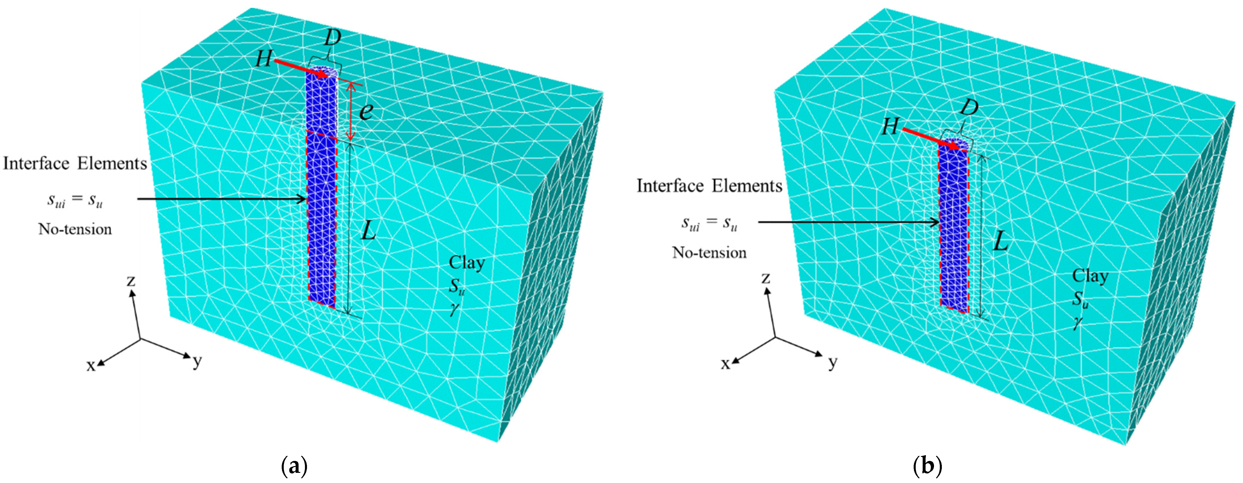
2. Method of Analysis

To derive numerical solutions for the undrained lateral capacity of 3D rigid circular piles, the commercial software OptumG3 (Copenhagen, Denmark) [44] is employed. The historical development of 3D FELA can be found in Lyamin and Sloan [45,46], Kranbbenhoft et al. [47], Sloan [48], Keawsawasvong and Ukritchon [49], Ukritchon and Keawsawasvong [50], and Ukritchon et al. [51,52].
Figure 1 shows the problem statement of 3D rigid circular piles using 3D meshes from OptumG3. A free-headed (unrestrained) pile is shown in Figure 1a, whilst Figure 1b shows a fixed-headed (restrained) pile. The pile is subjected to a horizontal load (H). Since the problem of a monotonically and laterally loaded pile is symmetrical, only half of the model is used in all analyses. The rigid circular pile has a diameter (D) and a length (L). To model the interface between piles and soils, zero-thickness interface elements are used. The undrained shear strength at the interface is equal to that of the surrounding soil (i.e., sui = su) which means that the adhesion factor at the interface is equal to one (α = 1). In addition, the tension cut-off condition at the soil–pile interface is adopted, which allows the soil to separate from the back of the circular pile whenever “necessary” during the solution process (see [17,53,54,55]). Additionally, the tension cut-off condition is implemented at the soil–pile interface, allowing the soil to separate from the rectangular pile’s backside since it was required throughout the solution procedure. By using OptumG3, the interface elements are added at the soil–pile interface, where the properties of this interface are the same as the surrounding clay, except the tension stresses are not allowed to take place at the interface. The surrounding clay is defined as homogeneous and isotropic clays with an elastic–perfectly plastic material obeying the Tresca failure criterion. The soil parameters required for the model are the undrained shear strength (su) and the soil unit weight (γ). Note the eccentric length (e) in a free-headed pile (see Figure 1a). On the other hand, in Figure 1b, there is no eccentric length for a fixed-headed pile since the top of the pile is restrained against vertical movement and thus pile rotation. Sloan [48] stated that the stability analysis using the FELA based on the limit analysis theory requires only the conventional strength parameters, such as undrained shear strength, but does not use the deformation parameters, such as Poisson’s ratio and Young’s modulus, which is different from the conventional displacement-based FEM. Thus, the Poisson’s ratio and Young’s modulus are not considered in this study using FELA. Hence, the displacements of the pile cannot be investigated by using FELA.
In all numerical analyses of the paper, the model domains are built to be sufficiently large so that collapsible areas are fully contained, and the failure zone would not reach or intersect the far boundaries of the model. The boundary conditions shown in Figure 2 are described next. At the domain bottom, zero velocity is applied in x-y-z directions so that there is no movement in the bottom plane in any direction. On all three side-planes, only the velocity in normal directions is fixed so that the roller supports are applied along all side planes. This condition is the same as the symmetrical plane where all nodes are fixed in the normal direction. The other two tangential directions are free to move. On the top plane of soils is a free surface, and the nodes are free to move in all directions. Note that a special boundary condition is given to the fixed-headed pile, where movement in the vertical direction is not permitted at the pile cap. In this way, no rotation can occur to the pile. The sizes of boundaries are selected to be large enough to confirm the failure zones are captured within the boundary domain so that it cannot cause an insignificant effect on the computed FELA solutions. However, the extremely large size of the domain can result in an increase in the number of elements directly reducing the computational performance of numerical simulations (i.e., increasing calculation time). Based on several trial-and-error checks, the optimal sizes of the model are 5D × 10D × 1.4 L for the width, length, and depth of the domain (see Figure 2).
One of OptumG3’s advanced features is the automatic adaptive mesh refinement scheme, which is based on the previous development in Ciria et al. [56]. The numbers of meshes in sensitive zones with very high shear power dissipation, which is the control variable for error estimation in all analyses, are automatically increased through successive iterations using the adaptive technique. The original and targeted number of elements used in all numerical runs are 5000 and 10,000 elements with five adaptive iterations [57,58,59,60,61,62]. Utilizing the adaptive mesh techniques, meshes will automatically enlarge in sensitive zones with considerable plastic shearing strain. All numerical simulations employ 5000 to 10,000 elements as the initial and goal number of elements, respectively, with five adaptive iterations. Examples of the final mesh refinements for a free-headed pile and a fixed-headed pile are shown in Figure 2a,b, respectively.
In the proposed study, six dimensional parameters of laterally loaded piles are considered; they are (H, n, D, L, Su, and γ ). These six parameters can be further reduced to the following dimensionless parameters as:
For fixed-headed piles:
H/(suLD) = f (L/D, n)
For free-headed piles:
H/(suLD) = f (L/D, n, e/D)
where H/(suLD) is the normalized horizontal load factor and it is a function of (L/D, n, and e/D), depending on whether it is a free- or a fixed-headed pile. (L/D) is the ratio of pile length to diameter, (n = γL/su) is the overburden stress factor, and (e/D) is the ratio of eccentric length to pile diameter.
The n parameter may be interpreted as the degree of the total overburden pressure of soil at the pile tip as compared to its average undrained shear strength. Conversely, the reciprocal of n may be interpreted as the ratio of the average undrained shear strength of soil normalized by the total overburden pressure. The special condition of n = 0 corresponds to the ideal case of weightless soil (i.e., γ = 0). The ranges of the overburden stress factor n are chosen to be n = 0 to 80 in the study. The selected pile length–diameter ratios are L/D = 5 to 60 and the ratio of eccentric length to pile diameter are e/D = 0 to 16. These dimensionless parameters can be simply used in practice as they were employed by Keawsawasvong [Sauer] to investigate the undrained capacity of loaded circular piles under combined horizontal load and moment. Furthermore, it may be used to validate the accuracy of the current solutions to those suggested by Keawsawasvong [63], Izadi and Chenari [25], and Brom [10]. For the range of e/D = 0–16, we follow the same length as proposed by Brom [10].
It is important to note that this study uses the rigorous LB and UB FELA to derive rigorous solutions of laterally loaded piles by also considering the soil weight, whereas the solutions in the original work by Broms [10] were obtained from the limit equilibrium method with the assumptions of weightless soils.

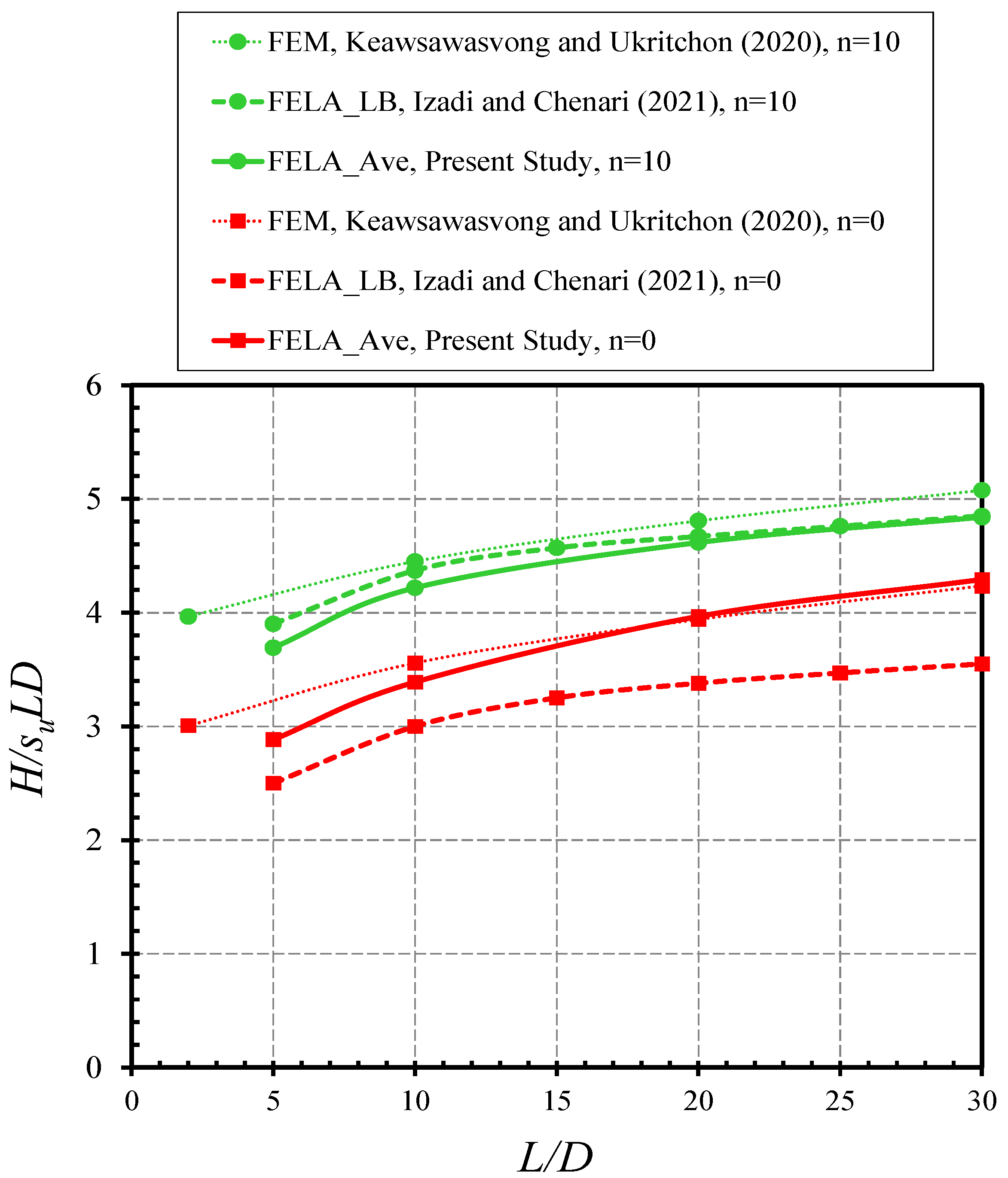
3. Comparisons with Published Results

To verify the numerical results presented in the paper, Figure 3 compares the free-headed results of the present study with those from the displacement finite element method (FEM) by Keawsawasvong and Ukritchon [17] as well as the lower bound (LB) finite element limit analysis (FELA) by Izadi and Chenari [25]. The presented results are the average solutions of H/(suLD) from the UB and LB solutions, and they are for cases of e/D = 0 and n = γL/su = (0, 5, and 10). In general, the present average solutions are in good agreement with those published solutions. All solutions indicate that an increase in L/D results in a nonlinear rise of H/(suLD). The larger the overburden stress factor n, the greater the H/(suLD). For n = 0 (i.e., weightless soil), the LB solutions by Izadi and Chenari [25] are over-conservative as they are lower than the present solutions by 15–20%.
For the verification of fixed-headed piles, Figure 4 shows a comparison between the averaged LB and UB results with those from the displacement-based finite element method (FEM) by Keawsawasvong [63] and the limit equilibrium method (LEM) from Brom [10]. Numerical results have shown that the averaged LB and UB solutions agree very well with those solutions produced by Keawsawasvong [63]. Nevertheless, the LEM solutions by Brom [10] are much lower than the present solutions. This is due to the assumption of the failure mechanisms used in the LEM method by Brom [10] were not quite correct since the wedge-shaped failure was used in his analysis. It is necessary to re-examine the failure mechanisms assumed in their analytical UB and LEM studies. This has also highlighted the advantages of using the current FELA technique, in which a prior assumption of the failure mechanism is not needed [48].
A comprehensive comparison with the classic LEM solutions in Broms [10] is presented in Figure 5 for both fixed-headed piles and free-headed piles with e/D = 0–16. Since the work presented by the author did not consider the soil unit weight, therefore, the comparison is for the case of n = 0. Numerical comparisons have shown that Broms’s LEM solutions are conservative, as they are consistently lower than those in the present study for all cases of both free- and fixed-headed piles.
The above three comparisons have improved the confidence in using the numerical results produced in the paper. Consequently, a series of parametric studies are presented in the next section.

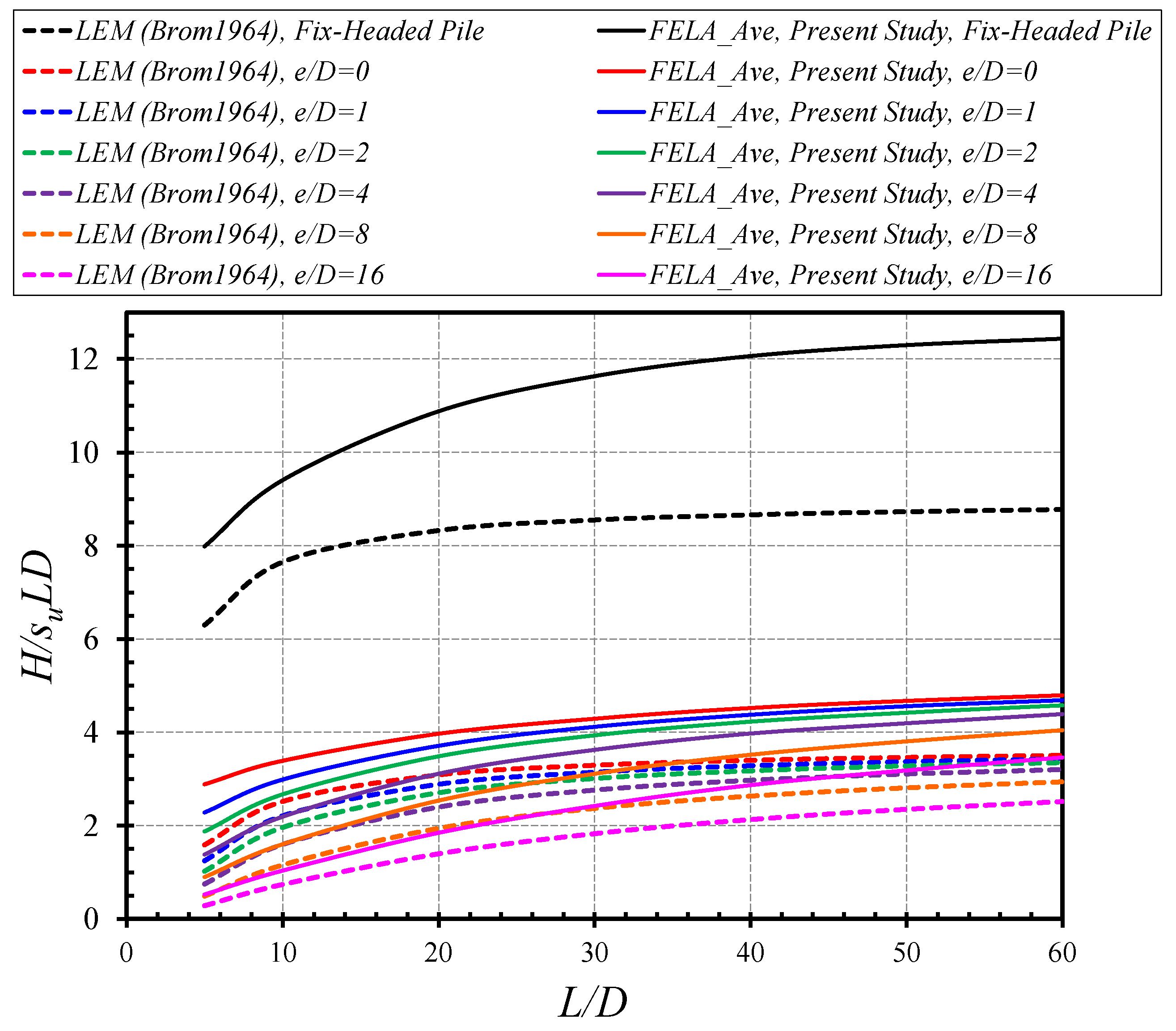
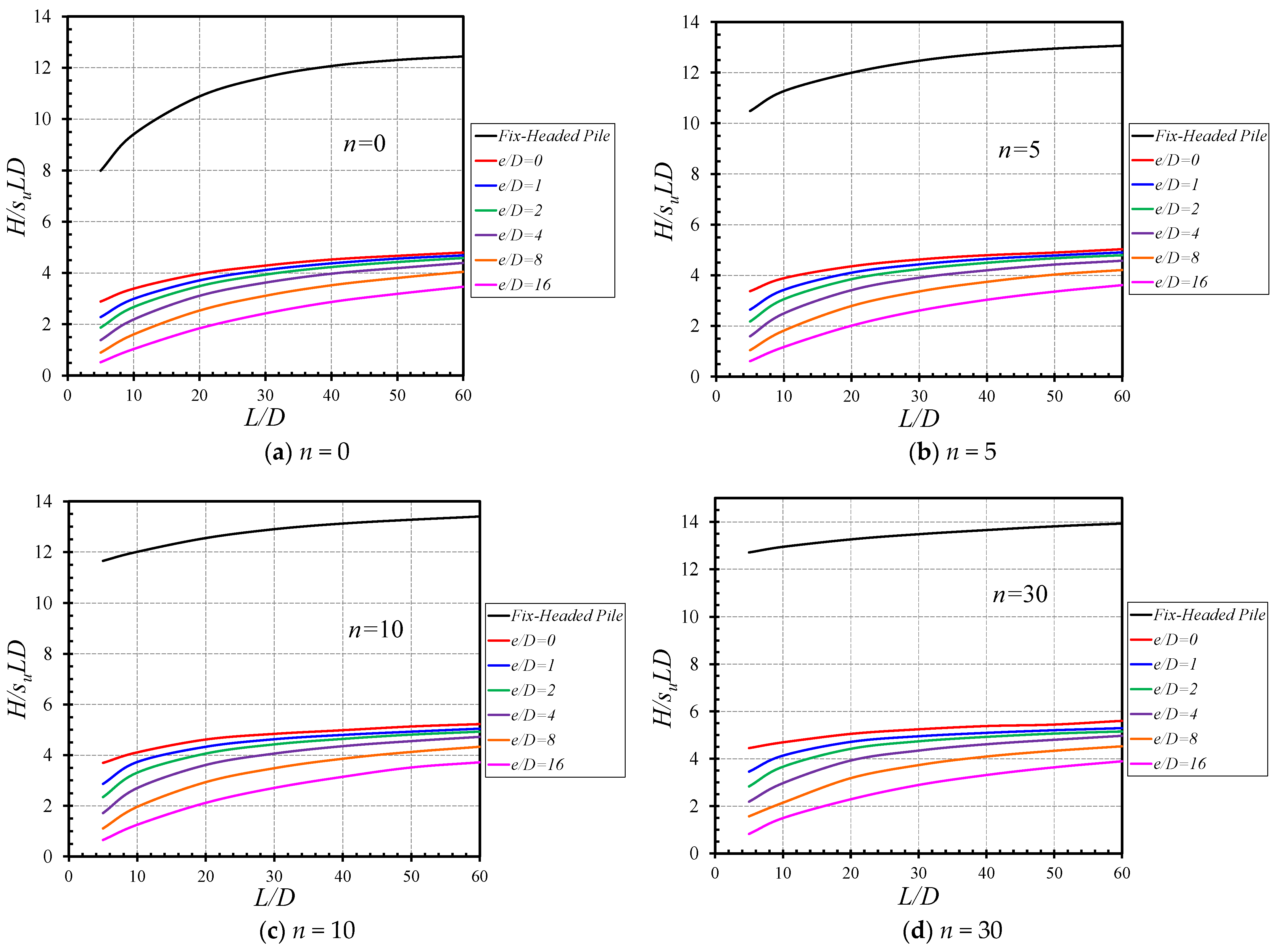
4. Results and Discussion

This section presents parametric studies for the following three dimensionless parameters, namely, the overburden stress factor (n), the pile length-diameter ratio (L/D), and the ratio of eccentric length to diameter (e/D). The effects of the individual parameter on the undrained lateral capacity of piles are examined using the normalized horizontal load factor H/(suLD).
The influences of L/D on H/(suLD) are presented in Figure 6 for the various values of (e/D = 0–16) and (n = 0–80). In Figure 6a, where n = 0, an increase in L/D results in a nonlinear increase in H/(suLD). The larger the e/D, the smaller the H/(suLD). Numerical results have shown that the fixed-headed piles yield greater values of H/(suLD) than those of the free-headed piles. Interestingly, the difference between the two piles is not small which is about three times larger than the free-headed pile with e/D = 0. The same observation applies to other values of n, which are also presented in Figure 6b–f. The maximum and minimum values of each case (different n and e/D) can be found in Table 2.
Figure 7 shows the effects of e/D on H/(suLD) for free-headed piles. Presented in Figure 7a is for L/D = 5. Numerical results have shown that increasing the value of e/D can significantly decrease H/(suLD). Note that the relationship between H/(suLD) and e/D is nonlinear in Figure 7a since the length of the pile is small, so the impact of the eccentricity on the lateral force is still significant. On the other hand, for large L/D, such as the one shown in Figure 7b with L/D = 60, a reduction of H/(suLD) as e/D increases is reported, where the function is almost linear when e/D is approximately larger than 4. One possible reason for this could be due to the better and more uniform stress distribution for piles with large L/D so that the impact of the eccentricity on the lateral force becomes less.
Figure 8 presents the influences of n on H/(suLD) for the various values of L/D. In Figure 8a (e/D = 0), numerical results have shown a nonlinear increase with the increasing n values. It is to be noted that the individual nonlinear curve reaches a constant value of H/(suLD) at approximately n = 50. On the other hand, as for e/D = 16 (see Figure 8b), the nonlinear curves are much flatter. The gradients are significantly lower than those in Figure 8a (e/D = 0).
As for fixed-headed piles, Figure 9 presents the effects of L/D on H/(suLD) for the various values of n. Similar to the free-head piles, H/(suLD) increases nonlinearly with the increasing L/D. It is interesting to see that the gradient of the nonlinear curve decreases (the curve becomes flattered) as the value of n increases. Note that the smallest H/(suLD) corresponds to the cases of n = 0. Moreover, see the case of n = 80 with a near linear line. This is mostly due to the effect of the large overburden stress factor n = γL/su. It can therefore be concluded that the effect of n on H/(suLD) cannot be neglected in the design of piles subject to lateral loading. A similar observation can be made with respect to Figure 10, where the relationship between n and H/(suLD) is shown for the various values of L/D. A nonlinear increase is depicted as n increases. The larger the L/D, the greater the H/(suLD). The rate of increase (gradient) is the smallest when L/D is the largest.
It is common to use the contour plots of shear dissipation to depict possible failure mechanisms of a soil structure, as it provides a good indicator of the intensity of non-zero plastic strains. Technically speaking, the actual values of the contour are not important in such a perfectly plastic material model, and therefore the contour bars for these plots are not normally shown in technical documents. Figure 11 shows the failure mechanisms of a free-headed pile with six different overburden stress factors (n = γL/su). The chosen free-headed pile is for (e/D = 0, L/D = 20). As n increases (i.e., the overburden stress increases), the size of the passive failure zone (see the area near the ground surface) decreases. Accompanying this is an increase in the size in the active failure zone (see the area near the pile tip, especially for n = 50 and 80).
In Figure 12, the effects of the ratio of eccentric length to pile diameter e/D on the failure mechanisms of a free-headed pile are presented. The chosen free-headed pile is for (n = 10, L/D = 30). As e/D increases (i.e., the pile length above the ground surface increases), the size of the passive failure zone (see the colored area near the ground surface) decreases. Nevertheless, unlike in Figure 11, the developed active zone near the pile tip is not pronounced. One of the possible reasons for this could be attributed to a location change of the inflection point of the pile as e/D increases.
For the chosen fixed-headed pile study (e/D = 0, L/D = 30), Figure 13 shows the failure mechanisms of six different overburden stress factors (n = γL/su). By fixing the vertical movement of a fixed-headed pile, only horizontal translations are allowed. This is similar to the classical passive earth pressure problem. We can therefore expect that, for the weightless case with n = 0, a full passive failure zone can be developed. This is seen in Figure 13a. As n increases, the overburden stress increases, and the overall size of the passive zone reduces, resulting in partially mobilized passive zones. It can therefore be concluded that the overburden stress factor n plays an important role in the determination of piles subject to lateral loading.

5. Empirical Design Equations

For research to be practical and used by engineers, it is literally important to develop accurate design equations. By employing a nonlinear regression analysis to the computed solutions, a mathematical expression of H/(suLD) is proposed using the combined relationship between power functions of L/D and n. This is shown in Equation (3) as follows:
H s u L D = a 1 + a 2 n + a 3 n 0.5 + ( b 1 + b 2 n + b 3 n 0.5 ) ( L D ) + ( c 1 + c 2 n + c 3 n 0.5 ) ( L D ) 0.5
where (a1 to a3), (b1 to b3), and (c1 to c3) are constant coefficients and they are presented in Table 3 for practical uses. The least-square method proposed by Sauer [64] was employed to determine the optimal values of these coefficients. Even though both sides of Equation (3) have the parameters L and D, they are in fact dimensionless parameters. To use the design Equation (3), the values of e, L and D should be defined first. Then, the values of n, e/D, and L/D are computed based on the soil investigation results (e.g., γ and su). Substituting n and L/D into Equation (3), the value of H/(suLD) is then obtained. By multiplying the value of H/(suLD) with su, L, and D, the result of H can be acquired which can be used as a maximum lateral force that a pile can resist.
A comparison of the H/(suLD) values between the FELA solutions (Avg) and the proposed design equation is shown in Figure 14 for the purpose of verifying the equation uses for the fixed-headed piles. For the free-headed piles, the comparisons are shown in Figure 15a–d, respectively, for the four different values of e/D. The comparisons have shown that the coefficients of determination (R2) are all greater than 99.44%. The proposed Equation (3) is considered as highly accurate with the coefficients provided in Table 3, and it can be used with confidence in practice to estimate the lateral capacity of a pile in cohesive soil.

6. Design Charts Limitations

The undrained lateral resistance of circular piles is investigated using the UB and LB limit analysis methodologies. Note that the following are some limitations that need to be investigated further:
  • All computed design charts are based on the assumption of undrained clay and homogenous soil profile characteristics, and hence cannot be used under heterogeneity and drained soil circumstances. Furthermore, the current solutions are inapplicable to non-homogeneous or multi-layered soils.
  • The solutions for circular piles in homogeneous clays are presented in this paper. Since the pile shapes differ, such as a rectangular pile, the current solutions are simply for comparison. Additional pile forms must be properly simulated.
  • If there are two adjacent piles, the effects of their separation must be explored further using a three-dimensional FELA technique.

7. Conclusions

The problem of lateral resistance of free- and fixed-headed piles in cohesive soils has been re-visited in this paper using advanced three-dimensional finite element limit analysis with upper and lower bound solutions. Three major considerations were given to study the effects of the ratio of pile length to diameter, the ratio of eccentric length to pile diameter and the overburden stress factor. Numerical solutions were defined by a normalized horizontal load factor that is similar in form to Broms’s original design charts. The analyses allowed for no-tension (separation) conditions at the interface of piles with zero-thickness interface elements. Several failure mechanisms from the parametric studies were discussed. The following conclusions are drawn based on the study.
For fixed-headed piles, the normalized horizontal load factor H/(suLD) increases nonlinearly with the increasing pile length to diameter ratio L/D and the overburden stress factor n. The increase is less pronounced as the value of the overburden stress factor n increases. In regard to the failure mechanism, the overall size of the passive zone reduces as the overburden stress factor n increases. The fixed-headed piles predict greater values of H/(suLD) than those from free-headed piles. The difference between the two piles is about three times larger than the free-headed piles.
For free-headed piles, same as in the fixed-headed piles, an increase in L/D and n would result in a nonlinear increase in H/(suLD). Numerical results have shown that increasing the value of e/D can significantly decrease H/(suLD). As n increases (i.e., the overburden stress increases), the size of the passive failure zone decreases. This has turned out to be an increase in the size of the active failure zone near the pile tip when the value n is large. In addition, as e/D increases (i.e., the pile length above the ground surface increases), the size of the passive failure zone decreases.
An accurate empirical design equation for predicting the undrained lateral capacity of both fixed- and free-headed piles was developed with design constants provided in a table. The provided equation and design charts can be used by practitioners with great confidence in the evaluation of lateral resistance of free- and fixed-headed piles.

Author Contributions

W.C.: Data curation, Software, Investigation, Methodology, Writing—original draft; J.S.: Methodology, Writing—review & editing, Supervision; C.N.: Methodology, Validation, Writing –original draft; C.T.: Methodology, Validation, Writing –original draft; P.J.: Methodology, Writing—review & editing, Project administration, Supervision, Funding acquisition; S.K.: Formal analysis, Software, Methodology, Writing—original draft; Writing—review, revising & editing. All authors have read and agreed to the published version of the manuscript.

Funding

This research was funded by National Science, Research and Innovation Fund (NSRF), and King Mongkut’s University of Technology North Bangkok with Contract no. KMUTNB-FF-65-38.

Institutional Review Board Statement

Not applicable.

Informed Consent Statement

Not applicable.

Data Availability Statement

All data, models, or code that support the findings of this study are available from the corresponding author upon reasonable request.

Acknowledgments

This study was supported by Thammasat University Research Fund, Contract No. TUFT33/2564.

Conflicts of Interest

The authors declare that they have no known competing financial interests or personal relationships that could have appeared to influence the work reported in this paper.

References

  1. Rathod, D.; Krishnanunni, K.T.; Nigitha, D. A Review on Conventional and Innovative Pile System for Offshore Wind Turbines. Geotech. Geol. Eng. 2020, 38, 3385–3402. [Google Scholar] [CrossRef]
  2. Ahangar-Asr, A.; Javadi, A.A.; Johari, A.; Chen, Y. Lateral load bearing capacity modelling of piles in cohesive soils in undrained conditions: An intelligent evolutionary approach. Appl. Soft Comput. J. 2014, 24, 822–828. [Google Scholar] [CrossRef]
  3. Johari, A.; Kalantari, A.R. System reliability analysis of soldier-piled excavation in unsaturated soil by combining random finite element and sequential compounding methods. Bull. Eng. Geol. Environ. 2021, 80, 2485–2507. [Google Scholar] [CrossRef]
  4. Nakhaee, M.; Johari, A. Genetic-based modeling of undrained lateral load capacity of piles in cohesion soil. Glob. J. Sci. Eng. Technol. 2013, 2013, 123–133. [Google Scholar]
  5. Ukritchon, B.; Keawsawasvong, S. Unsafe error in conventional shape factor for shallow circular foundations in normally consolidated clays. J. Geotech. Geoenviron. Eng. 2017, 143, 02817001. [Google Scholar] [CrossRef]
  6. Ukritchon, B.; Keawsawasvong, S. Design equations of uplift capacity of circular piles in sands. Appl. Ocean Res. 2019, 90, 101844. [Google Scholar] [CrossRef]
  7. Ukritchon, B.; Keawsawasvong, S. Undrained lower bound solutions for end bearing capacity of shallow circular piles in non-homogeneous and anisotropic clays. Int. J. Numer. Anal. Methods Geomech. 2020, 44, 596–632. [Google Scholar] [CrossRef]
  8. Keawsawasvong, S.; Shiau, J.; Yoonirundorn, K. Bearing capacity of cylindrical caissons in cohesive-frictional soils using axisymmetric finite element limit analysis. Geotech. Geol. Eng. 2022, 40, 3929–3941. [Google Scholar] [CrossRef]
  9. Lai, V.Q.; Shiau, J.; Keawsawasvong, S.; Tran, D.T. Bearing capacity of ring foundations on anisotropic and heterogenous clays: FEA, NGI-ADP, and MARS. Geotech. Geol. Eng. 2022, 40, 3913–3928. [Google Scholar] [CrossRef]
  10. Broms, B.B. Lateral resistance of piles in cohesive soils. J. Soil Mech. Found. 1964, 90, 27–63. [Google Scholar] [CrossRef]
  11. Meyerhof, G.G.; Mathur, S.K.; Valsangkar, A.J. Lateral resistance and deflection of rigid walls and piles in layered soils. Can. Geotech. J. 1981, 18, 159–170. [Google Scholar] [CrossRef]
  12. Georgiadis, K.; Georgiadis, M.; Anagnostopoulos, C. Lateral bearing capacity of rigid piles near clay slopes. Soils Found. 2013, 53, 144–154. [Google Scholar] [CrossRef] [Green Version]
  13. Georgiadis, K.; Georgiadis, M. Undrained lateral pile response in sloping ground. J. Geotech. Geoenviron. Eng. 2010, 136, 1489–1500. [Google Scholar] [CrossRef]
  14. Georgiadis, K. Variation of limiting lateral soil pressure with depth for pile rows in clay. Comput. Geotech. 2014, 62, 164–174. [Google Scholar] [CrossRef]
  15. Zhang, Y.; Andersen, K.H.; Tedesco, G. Ultimate bearing capacity of laterally loaded piles in clay—Some practical considerations. Mar. Struct. 2016, 50, 260–275. [Google Scholar] [CrossRef]
  16. Al-Abboodi, I.; Sabbagh, T.T. Numerical Modelling of Passively Loaded Pile Groups. Geotech. Geol. Eng. 2019, 37, 2747–2761. [Google Scholar] [CrossRef] [Green Version]
  17. Keawsawasvong, S.; Ukritchon, B. Failure modes of laterally loaded piles under combined horizontal load and moment considering overburden stress factors. Geotech. Geol. Eng. 2020, 38, 4253–4267. [Google Scholar] [CrossRef]
  18. Sivapriya, S.V.; Gandhi, S.R. Soil–Structure Interaction of Pile in a Sloping Ground under Different Loading Conditions. Geotech. Geol. Eng. 2020, 38, 1185–1194. [Google Scholar] [CrossRef]
  19. Conte, E.; Pugliese, L.; Troncone, A.; Vena, M. A simple approach for evaluating the bearing capacity of piles subjected to inclined loads. Int. J. Geomech. 2021, 21, 04021224. [Google Scholar] [CrossRef]
  20. Eltaweila, S.; Shahien, M.M.; Nasr, A.M.; Farouk, A. Effect of Soil Improvement Techniques on Increasing the Lateral Resistance of Single Piles in Soft Clay (Numerical Investigation). Geotech. Geol. Eng. 2021, 39, 4059–4070. [Google Scholar] [CrossRef]
  21. Murff, J.D.; Hamilton, J.M. P-ultimate for undrained analysis of laterally loaded piles. J. Geotech. Geoenviron. Eng. 1993, 119, 91–107. [Google Scholar] [CrossRef]
  22. Klar, A.; Randolph, M.F. Upper-bound and load-displacement solution for laterally loaded piles in clays based on energy minimization. Géotechnique 2008, 58, 815–820. [Google Scholar] [CrossRef]
  23. Yu, J.; Huang, M.; Zhang, C. Three-dimensional upper-bound analysis for ultimate bearing capacity of laterally loaded rigid pile in undrained clay. Can. Geotech. J. 2015, 52, 1775–1790. [Google Scholar] [CrossRef]
  24. Yu, J.; Huang, M.; Zhang, C. Ultimate lateral resistance of laterally loaded piles in undrained clay. In Proceedings of the 3rd International Symposium on Frontiers in Offshore Geotechnics (ISFOG), Oslo, Norway, 10–12 June 2015; Meyer, V., Ed.; Taylor & Francis Group: Abingdon, UK, 2015; pp. 661–666. [Google Scholar]
  25. Izadi, A.; Chenari, R.J. Three-dimensional finite-element lower bound solutions for lateral limit load of piles embedded in Cross-Anisotropic Clay Deposits. Int. J. Geomech. 2021, 21, 04021234. [Google Scholar] [CrossRef]
  26. Izadi, A.; Chenari, R.J. Three dimensional undrained bearing capacity analysis of laterally loaded pile in heterogeneous marine deposits. Mar. Georesour. Geotechnol. 2022, 40, 213–234. [Google Scholar] [CrossRef]
  27. Luo, R.; Zhu, B.; Yang, Z. Limiting Force Profile for Laterally Loaded Piles in Undrained Clay. Int. J. Geomech. 2021, 21, 04021146. [Google Scholar] [CrossRef]
  28. Reese, L.C. Laterally loaded piles: Program documentation. J. Geotech. Geoenviron. Eng. 1977, 103, 287–305. [Google Scholar] [CrossRef]
  29. Ismael, N.F. Behavior of laterally loaded bored piles in cemented sands. J. Geotech. Geoenviron. Eng. 1990, 116, 1678–1699. [Google Scholar] [CrossRef]
  30. Reese, L.C.; Wang, S.T.; Isenhower, W.M.; Arrellaga, J.A. Computer Program LPILE Plus Version 4.0 Technical Manual; Ensoft, Inc.: Austin, TX, USA, 2000. [Google Scholar]
  31. Yu, H.; Peng, S.; Zhao, Q. Field Tests of the Response of Single Pile Subjected to Lateral Load in Gravel Soil Sloping Ground. Geotech. Geol. Eng. 2019, 37, 2659–2674. [Google Scholar] [CrossRef]
  32. Ghasemipanah, A.; Moayed, R.Z. Analysis of Concrete Piles Under Horizontal and Vertical Simultaneous Loading with P-Y Method and Finite Element Analysis. Geotech. Geol. Eng. 2021, 39, 5857–5877. [Google Scholar] [CrossRef]
  33. Randolph, M.F.; Houlsby, G.T. The limiting pressure on a circular pile loaded laterally in cohesive soil. Geotechnique 1984, 34, 613–623. [Google Scholar] [CrossRef]
  34. Martin, C.; Randolph, M.F. Upper-bound analysis of lateral pile capacity in cohesive soil. Geotechnique 2006, 56, 141–145. [Google Scholar] [CrossRef]
  35. Ukritchon, B.; Keawsawasvong, S. Error in Ito and Matsui’s limit equilibrium solution of lateral force on a row of stabilizing piles. J. Geotech. Geoenviron. Eng. 2017, 143, 02817004. [Google Scholar] [CrossRef]
  36. Lai, V.Q.; Banyong, B.; Keawsawasvong, S. Stability of limiting pressure behind soil gaps in contiguous pile walls in anisotropic clays. Eng. Fail. Anal. 2022, 134, 106049. [Google Scholar] [CrossRef]
  37. Keawsawasvong, S.; Ukritchon, B. Ultimate lateral capacity of two dimensional plane strain rectangular pile in clay. Geomech. Eng. 2016, 11, 235–251. [Google Scholar] [CrossRef]
  38. Ukritchon, B.; Keawsawasvong, S. Undrained lateral capacity of rectangular piles under a general loading direction and full flow mechanism. KSCE J. Civ. Eng. 2018, 22, 2256–2265. [Google Scholar] [CrossRef]
  39. Keawsawasvong, S.; Ukritchon, B. Undrained lateral capacity of I-shaped concrete piles. Songklanakarin J. Sci. Technol. 2017, 39, 751–758. [Google Scholar]
  40. Poulos, H.G.; Davis, E.H. Pile Foundation Analysis and Design; Wiley: New York, NY, USA, 1980. [Google Scholar]
  41. Reese, L.C.; Van Impe, W.F. Single Piles and Pile Groups under Lateral Loading; Taylor & Francis Group plc: London, UK, 2007. [Google Scholar]
  42. Ruigrok, J.A.T. Laterally Loaded Piles Models and Measurements. Ph.D. Thesis, Delft University of Technology, Delft, The Netherlands, 2010. [Google Scholar]
  43. Zhang, Y.; Rochmann, F.N.; Teng, Y.; Lai, Y. A numerical study on the group effect for offshore piles in clay under lateral loading. Mar. Struct. 2021, 84, 103238. [Google Scholar] [CrossRef]
  44. Optum CE (2022) OptumG3. Optum Computational Engineering, Copenhagen. Available online: https://optumce.com/ (accessed on 12 September 2022).
  45. Lyamin, A.V.; Sloan, S.W. Lower bound limit analysis using nonlinear programming. Int. J. Numer. Methods Eng. 2002, 55, 573–611. [Google Scholar] [CrossRef]
  46. Lyamin, A.V.; Sloan, S.W. Upper bound limit analysis using linear finite elements and nonlinear programming. Int. J. Numer. Anal. Methods Géoméch. 2002, 26, 181–216. [Google Scholar] [CrossRef]
  47. Kranbbenhoft, K.; Lyamin, A.V.; Sloan, S.W. Formulation and solution of some plasticity problems as conic programs. Int. J. Solids Struct. 2007, 44, 1533–1549. [Google Scholar] [CrossRef] [Green Version]
  48. Sloan, S.W. Geotechnical stability analysis. Géotechnique 2013, 63, 531–572. [Google Scholar] [CrossRef]
  49. Keawsawasvong, S.; Ukritchon, B. Undrained basal stability of braced circular excavations in non-homogeneous clays with linear increase of strength with depth. Comput. Geotech. 2019, 115, 103180. [Google Scholar] [CrossRef]
  50. Ukritchon, B.; Keawsawasvong, S. Three-dimensional lower bound finite element limit analysis of Hoek-Brown material using semidefinite programming. Comput. Geotech. 2018, 104, 248–270. [Google Scholar] [CrossRef]
  51. Ukritchon, B.; Yoang, S.; Keawsawasvong, S. Three-dimensional stability analysis of the collapse pressure on flexible pavements over rectangular trapdoors. Transp. Geotech. 2019, 21, 100277. [Google Scholar] [CrossRef]
  52. Ukritchon, B.; Yoang, S.; Keawsawasvong, S. Undrained stability of unsupported rectangular excavations in non-homogeneous clays. Comput. Geotech. 2020, 117, 103281. [Google Scholar] [CrossRef]
  53. Keawsawasvong, S.; Ukritchon, B. Undrained capacity of laterally loaded underground walls subjected to horizontal load and moment. J. GeoEng. 2016, 11, 75–83. [Google Scholar]
  54. Keawsawasvong, S.; Ukritchon, B. Finite element analysis of undrained stability of cantilever flood walls. Int. J. Geotech. Eng. 2017, 11, 355–367. [Google Scholar] [CrossRef]
  55. Keawsawasvong, S.; Ukritchon, B. Three-dimensional interaction diagram for the undrained capacity of inverted T-shape strip footings under general loading. Int. J. Geotech. Eng. 2018, 12, 133–146. [Google Scholar] [CrossRef]
  56. Ciria, H.; Peraire, J.; Bonet, J. Mesh adaptive computation of upper and lower bounds in limit analysis. Int. J. Numer. Methods Eng. 2008, 75, 899–944. [Google Scholar] [CrossRef]
  57. Yodsomjai, W.; Keawsawasvong, S.; Senjuntichai, T. Undrained stability of unsupported conical slopes in anisotropic clays based on Anisotropic Undrained Shear failure criterion. Transp. Infrastruct. Geotechnol. 2021, 8, 557–568. [Google Scholar] [CrossRef]
  58. Yodsomjai, W.; Keawsawasvong, S.; Thongchom, C.; Lawongkerd, J. Undrained stability of unsupported conical slopes in two-layered clays. Innov. Infrastruct. Solut. 2021, 6, 15. [Google Scholar] [CrossRef]
  59. Yodsomjai, W.; Keawsawasvong, S.; Likitlersuang, S. Stability of unsupported conical slopes in Hoek-Brown rock masses. Transp. Infrastruct. Geotechnol. 2021, 8, 278–295. [Google Scholar] [CrossRef]
  60. Yodsomjai, W.; Keawsawasvong, S.; Lai, V.Q. Limit analysis solutions for bearing capacity of ring foundations on rocks using Hoek-Brown failure criterion. Int. J. Geosynth. Ground Eng. 2021, 7, 29. [Google Scholar] [CrossRef]
  61. Keawsawasvong, S.; Thongchom, C.; Likitlersuang, S. Bearing capacity of strip footing on Hoek-Brown rock mass subjected to eccentric and inclined loading. Transp. Infrastruct. Geotechnol. 2021, 8, 189–200. [Google Scholar] [CrossRef]
  62. Keawsawasvong, S.; Lai, V.Q. End bearing capacity factor for annular foundations embedded in clay considering the effect of the adhesion factor. Int. J. Geosynth. Ground Eng. 2021, 7, 15. [Google Scholar] [CrossRef]
  63. Keawsawasvong, S. Limit State Solutions of Laterally Loaded Pile in Cohesive Soils by Finite Element Analysis. Master’s Thesis, Chulalongkorn University, Bangkok, Thailand, 2014. [Google Scholar]
  64. Sauer, T. Numerical Analysis; Pearson Education Limited: London, UK, 2014. [Google Scholar]
Figure 1. Problem geometries and dimensions: (a) free-headed pile (b) fixed-headed pile.
Sustainability 14 12940 g001
Figure 2. FELA models, 3D meshes, and boundary conditions: (a) free-headed pile (b) fixed-headed pile.
Sustainability 14 12940 g002
Figure 3. Comparison of H/(suLD) of free-headed piles.
Sustainability 14 12940 g003
Figure 4. Comparison of H/(suLD) of fixed-headed piles.
Sustainability 14 12940 g004
Figure 5. Comparison of H/(suLD) between the present study and the previous solutions from Broms’s original charts.
Sustainability 14 12940 g005
Figure 6. Influence of L/D on H/(suLD)—free- and fixed- headed piles. (a) n = 0; (b) n = 5; (c) n = 10; (d) n = 30; (e) n = 50; (f) n = 80.
Sustainability 14 12940 g006aSustainability 14 12940 g006b
Figure 7. Influence of e/D on H/(suLD)—free-headed piles. (a) L/D = 5; (b) L/D = 60.
Sustainability 14 12940 g007
Figure 8. Influence of n on H/(suLD)—free-headed piles. (a) e/D = 0; (b) e/D = 16.
Sustainability 14 12940 g008
Figure 9. Influence of L/D on H/(suLD)~fixed-headed piles.
Sustainability 14 12940 g009
Figure 10. Influence of n on H/(suLD)—fixed-headed piles.
Sustainability 14 12940 g010
Figure 11. Effect of n on failure mechanisms (free-headed, e/D = 0, L/D = 20). (a) n = 0; (b) n = 5; (c) n = 10; (d) n = 30; (e) n = 50; (f) n = 80.
Sustainability 14 12940 g011
Figure 12. Effect of e/D on failure mechanisms (free-headed, L/D = 30, n = 10). (a) e/D = 0; (b) e/D = 1; (c) e/D = 2; (d) e/D = 4; (e) e/D = 8; (f) e/D = 16.
Sustainability 14 12940 g012
Figure 13. Effect of n on failure mechanisms (fixed-headed, e/D = 0, L/D = 30). (a) n = 0; (b) n = 5; (c) n = 10; (d) n = 30; (e) n = 50; (f) n = 80.
Sustainability 14 12940 g013aSustainability 14 12940 g013b
Figure 14. Comparisons between the results from FELA and proposed design equations (fixed-headed piles).
Sustainability 14 12940 g014
Figure 15. Comparisons between the results from FELA and proposed design equations (free-headed piles) (a) e/D = 0; (b) e/D = 4; (c) e/D = 8; (d) e/D = 16.
Sustainability 14 12940 g015
Table 1. Summary of the existing methods.
Existing Method Equations or Design Charts
Broms [10] H s u D 2 = 27 2 9 L D + 9 2 18 + 8 L 2 D 2
Meyerhof et al. [11] H s u L D = 2 F c s c , where FC = lateral resistance factor and sC = shape factor (see Meyerhof et al., 1981)
Georgiadis et al. [12] H s u D 2 = N p u ( 2 z o D L D ) + ( N p u N p 0 λ ) ,
where zo can be computed from the equation below:
ω 1 ( z o D ) 2 + ω 2 exp ( λ z o D ) + ω 2 ( z o D ) exp ( λ z o D ) + ω 3 = 0
in   which   λ = 0.55 0.15 α ,   ω 1 = N p u ,   ω 2 = 2 ( N p u N p 0 λ ) ,
ω 3 = N p u ( L 2 2 D 2 ) N p u N p 0 λ [ 1 λ + ( L D + 1 λ ) exp ( λ L D ) ] ,   N p 0 = 2 + 1.5 a   and   N p u = π + 2 arcsin a + 2 cos ( arcsin a ) + 4 [ cos ( arcsin a 2 ) + sin ( arcsin a 2 ) ]
Murff and Hamilton [21] H s u L D = f ( L D ) from a design chart
Yu et al. [23] H s u D 2 = f ( s u γ D , L D ) from a design chart
Keawsawasvong and Ukritchon [17] H s u L D = a 1 + ( a 2 n + a 3 a 4 n + 1 ) ( L D ) + ( a 5 n + a 6 a 7 n + 1 ) ( L D ) 0.5
where a1 = 4.3671, a2 = 3.8909 × 10⁻⁴, a3 = 6.5365 × 10⁻², a4 = 0.1056, a5 = 2.3647 × 10⁻², a6 = −0.3956, a7 = 8.1367 × 10⁻² and n = γL/su is the overburden stress factor.
Izadi and Chenari [25,26] H γ L D 2 = f ( s u γ D , L D , α , λ ) from a design chart
where α is adhesion factor and λ is strength gradient ratio
Table 2. Minimum and maximum values of 3D piles.
Pilese/DH/suLDn = 0n = 5n = 10n = 30n = 50n = 80
0Min2.8843.3723.6904.4544.8945.023
0Max4.7955.0325.2235.6015.7255.753
1Min2.2832.6422.8623.4524.2384.537
1Max4.6884.9085.0455.2945.4015.499
2Min1.8742.1742.3432.8253.6104.005
Free2Max4.5814.7894.9225.1555.2745.363
Headed4Min1.3821.5971.7122.1852.7513.124
4Max4.3884.5794.7224.9685.0515.133
8Min0.8991.0391.1091.5681.9082.289
8Max4.0434.2054.3304.5294.6364.693
16Min0.5240.6100.6490.8220.9791.136
16Max3.4623.6123.7163.8943.9784.033
Fixed-Min7.98510.48311.65312.70612.93113.193
Headed-Max12.43813.06613.39913.92414.54614.767
Table 3. Design coefficients for the proposed equations.
ConstantFree-Headed Pile, e/DFix-Headed
Coefficients0124816Pile
a11.396530.28330−0.26390−0.96210−1.26159−1.076573.87701
a20.011490.042160.065920.049930.046580.02330−0.16683
a30.296480.07840−0.14140−0.11097−0.14845−0.111622.41066
b1−0.04021−0.05908−0.06416−0.06593−0.04957−0.02122−0.14081
b20.000860.001850.002350.001890.001600.00059−0.00251
b3−0.00215−0.00902−0.01359−0.01128−0.00993−0.005140.03772
c10.742571.020441.116421.195231.065960.750752.18053
c2−0.00879−0.02003−0.02688−0.02136−0.01871−0.008150.03992
c3−0.000280.074800.137680.116310.109370.06751−0.56016
R298.83%99.28%99.59%99.75%99.87%99.73%99.44%
Publisher’s Note: MDPI stays neutral with regard to jurisdictional claims in published maps and institutional affiliations.

