1. Introduction
The Huaibei mining area is located in the Huang-Huai-Hai plain in the north of Anhui Province, China (see
Figure 1). The coal resources covered by rock and loose layer are buried to a certain extent. Additionally, they are mostly mined by the total subsidence method of roof management with longwall working faces [
1,
2]. Practices indicate that underground coal mining in Huaibei plain often causes a surface subsidence basin [
3,
4,
5,
6,
7], and the area of surface subsidence is often larger than that of the underground mining area. Additionally, the process of surface subsidence is often accompanied by a large number of ground fissures [
8]. Therefore, ground fissures are one of the most intuitive manifestations of surface damage after coal mining in the Huaibei mining area.
For the mined-out area of the Huaibei plain mining area with flat surface, when the underground coal mining reaches super-full mining, and there is no large geological structure within the mining influence area, the resulting coal mining subsidence basin usually contains three regions (see
Figure 2), including the middle region (CC′), the compression region (BC, B′C′) and the tensile region (AB, A′B′) [
9,
10]. Firstly, the middle region refers to the middle part of the subsidence basin, where the maximum subsidence occurs. Secondly, the compression region is generally located between the middle region and the boundary of the mined-out area, and the ground deformation in this region inclines to the center of the basin in a concave shape, resulting in compression deformation of the surface soil. Thirdly, the tensile region is generally located from the boundary of the mined-out area to the boundary of the basin, and the ground deformation in this region inclines to the center of the basin in a convex shape, resulting in tensile deformation of the surface soil.
The ground fissures associated with coal mining subsidence basins in Huaibei mining area can usually be divided into two types, namely marginal fissures and dynamic fissures [
11]. Firstly, the characteristic of marginal fissures are: (1) they are located in the outer edge area of the mining face (tensile region in
Figure 2); (2) their extension direction is close to the advancing direction of the working face; and (3) they are difficult to close immediately after their formation. Secondly, the characteristic of dynamic fissures are: (1) they are located on the surface above the working face (middle region and compression region in
Figure 2); (2) their extension direction is nearly perpendicular to the advancing direction of the working face; and (3) they are usually closed within a period of time after their formation [
12,
13,
14]. Numerous scholars have carried out meaningful studies on the developmental characteristics and mechanisms of coal mining ground fissures, pointing out that geological conditions, mining processes and the nature of the overlying rock and soil have significant effects on the formation and evolution of ground fissures [
15,
16,
17].
Coal mining ground fissures are harmful to the geological environment of mining areas in many ways. Firstly, ground fissures can directly damage surface structures such as railways, dams, villages and other industrial and civil buildings [
18,
19,
20]. Secondly, ground fissures can cause secondary geological disasters in mining area. For example, ground fissures can become a channel for surface water to enter mines and then lead to mine water disasters [
21]. In addition, ground fissures can also aggravate soil erosion and reduce soil quality, which can cause damage to the ecological environment of the mining area. For example, the formation of ground fissures in the woodland of mining areas can directly damage plant roots [
22,
23].
It is of great significance to prevent and control ground fissures in the Huaibei mining area. Numerous scholars have studied coal mining subsidence and ground fissure control measures based on mining technology, such as strip mining [
24,
25], filling mining [
26], reducing subsidence by grouting [
27,
28], etc. However, these methods may have the disadvantage of being too expensive. In addition, most of these existing measures control ground fissures indirectly via surface subsidence treatments. There were few direct prevention and control measures for coal mining ground fissures [
29]. Therefore, the humidification method, which has the advantage of low cost, was firstly proposed to prevent and control coal mining ground fissures. Specifically, the soil water content is increased to improve soil plasticity, which can slow or prevent the development of coal mining ground fissures. Then, two typical coal mining working faces and their subsidence basin in the Huaibei mining area were selected as the research objects, and the case study on the prevention and control of coal mining ground fissures was carried out based on the humidification method.
2. Basis of the Humidification Method
2.1. Method Principle
In the process of coal mining subsidence, discontinuous deformation of the surface soil occurs horizontally or vertically. When the strain in the soil exceeds a certain critical value, the ground fissure can be formed at this place [
30]. Ground fissures in the Huaibei plain mining area are usually formed from the surface. The width of the fissures decreases with the increase in depth, and finally disappears [
31,
32]. However, as a special granular material, soil strength and deformation properties are significantly affected by water content.
The loose layer in the Huaibei plain mining area are usually cohesive soils. Consistency is one of the most important physical state characteristics of cohesive soils. The consistency refers to the soft and hard degree of cohesive soils or its resistance to deformation or damage caused by external forces. With the increase in water content, the consistency of cohesive soils can change as follows: solid state→semi-solid state→plastic state→flow state. Additionally, the characteristics of loose soil with low water content: it is hard with solid or semi-solid state, and its deformation property is mainly elastic; under shear and compression stress, its damage occurs without large deformation. The characteristics of loose soil with high water content is: it is soft and plastic, and its deformation property is mainly plastic; under large shear and compression stress, its damage may be avoided by large deformation.
2.2. Experiment on the Influence of Water Content on Soil Fissures
2.2.1. Experimental Device
In this study, a home-made experimental device was used to study the influence of water content on soil fissure development, see
Figure 3. The device mainly consists of four parts, including the sample box, hinge, bracket and lift. The sample box is a rectangular structure consisting of a horizontal plate and several vertical plates, and its size is 100 cm × 40 cm × 30 cm. The hinge is arranged in the middle of the bottom of the sample box. The sample box is divided into two parts, part A and B, which can rotate relatively at the hinge. The bracket is L-shaped with high and low parts. Additionally, the higher part directly supports the sample box A, meanwhile, the lower part has a lift to support the sample box B. The lift is a mechanical lift, and its lifting height is 0~20 cm.
2.2.2. Experimental Process
Soil samples were collected from working face A (WFA) of the Huaibei Suntuan coal mine. For the soil samples, its particle-specific gravity (GS) is 2.74, plastic limit (WP) is 23.2% and liquid limit (WL) is 41.4%. The specific experimental procedure is as follows: (1) Grinding of soil samples: the soil sample was ground after drying and passed through a ten-mesh sieve. (2) Preparing soil samples with different water content: after mixing with water, the ground samples were stirred and infiltrated; then the soil samples with 30%, 35% and 40% water content were prepared and left for 24 h, respectively. (3) Loading of samples: the height of the lift was adjusted to keep the bottom of the sample box horizontal, then each soil sample with a certain water content can be loaded into the sample box. (4) Observation of fissures: via lowering the height of the lift top, the sample box B inclined down along the hinge, then the development characteristics of fissures on the soil sample surface can be observed.
During the experiment, the top of the lift declined at a uniform rate of 1 cm/min. When the lift top dropped to 1 cm and 2 cm, respectively, the lift was kept at rest for 1 h, and the development of fissures on the soil sample surface was observed. When the lift top dropped to 3 cm, the change in fissures was observed continuously for 24 h (the experiment showed that the fissure development was generally stable within 24 h). It is important to clarify that the sample was stratified compacted, and the density of the sample was controlled. The compacted soil samples of each layer need surface roughening before the samples continue to be loaded. In addition, the experiment was carried out in a relatively closed room. Additionally, the indoor air humidity was controlled by humidifying equipment, so that the water content of every prepared soil sample was relatively stable during the experiment.
2.2.3. Experimental Results and Analyses
As shown in
Figure 4, the experimental results indicate that:
Soil sample with a water content of 30% (the measured density is 1.29 g/cm3): when the top of the lift dropped 4 mm, small fissures appeared on the soil surface above the hinge. When the top dropped 1 cm, the fissures on the soil surface were basically penetrated with an average width of 0.5 mm. When the top dropped 2 cm, the fissures on the soil surface were completely penetrated with an average width of 3 mm. When the top dropped 3 cm, the average width of the fissures reached 7 mm.
Soil sample with a water content of 35% (the measured density is 1.29 g/cm3): when the top of the lift dropped 1 cm, there were no obvious fissures on the soil surface. When the top dropped 2 cm, the fissures appeared on the soil surface and gradually penetrated with an average width of 2 mm. When the top dropped 3 cm, the fissures on the soil sample surface were completely penetrated, and the average width of the fissures reached 4 mm.
Soil samples with a water content of 40% (the measured density is 1.28 g/cm3): no obvious fissures were found on the soil surface when the top of the lift dropped 1 cm, 2 cm and 3 cm.
In the experiment, the water contents of the soil samples were 30%, 35% and 40%, respectively. These water contents were between the plastic limit WP (23.2%) and the liquid limit WL (41.4%) of the soil samples. Therefore, during the experiment, the soil samples with different water contents were all in plastic state. The experimental results show that: (1) for soil samples with a certain water content, the fissure development degree can increase with the drop of the lift top, as shown in
Figure 4 a→b→c. (2) For soil samples with different water content, when the lift top dropped by the same amount, the plastic deformation capacity of the soil sample increased as the water content increased from 30%, 35% and 40%. Additionally, the development degree of fissures on the soil surface gradually decreased, as shown in
Figure 4 c→f→i. In particular, the plastic deformation capacity of the soil sample was further enhanced when the water content approached the liquid limit at 40%, so that no obvious fissures were found during the experiment. In summary, this experiment revealed that the change in water content had a significant effect on the development of fissures in cohesive soils. This is because with the increase of 174 water content, the shear strength of cohesive soil decreases, but at the same time, its plastic 175 deformation capacity increases. The results are consistent with the research of Erguler ZA and Ulusay R [
33].
3. Proposal of the Humidification Method
In this paper, the humidification method was proposed as a method to control coal mining ground fissures based on humidification of the soil. This method is to increase the soil water content by humidification method to enhance the plastic deformation capacity of the soil, which can then control or even avoid the development of coal mining ground fissures through plastic deformation in the process of surface subsidence. The main steps of the humidification method:
Through data collection and field investigation, the main information of coal mining, including the mining area, advancing direction and advancing speed of the working face, can be obtained. Then, the surface subsidence area and the subsidence time can be predicted.
Based on the measurement of the natural water content and the liquid and plastic limited water content of the soil layer in the surface subsidence area, the water requirement (volume) of soil humidification with a certain depth can be calculated, then the water and humidification tools must be prepared.
Combined with the advancing direction and speed of the working face, the humidification process of soil layer with a certain depth in the surface subsidence area should be completely finished before the humidification soil layer deformes due to subsidence. The water content of the soil after humidification reached its plastic limit water content.
For the humidification soil within the subsidence area, it can be properly watered during the whole subsidence deformation process (i.e., before the subsidence is stable), which can ensure that the water content of the soil is not lower than its plastic limit.
The following needs to be further clarified: Firstly, humidification water can be selected according to the site conditions, such as rivers, lakes and wells. Wetting tools can be selected according to the needs of water pumps, such as nylon hose. Secondly, in this study, the soil layer in the surface subsidence area was uniformly humidified. That is, the humidification depths of the soil layer were equal, and the humidification depths were determined according to the specific situation.
4. Field Experimental Process for the Humidification Method
4.1. Overview of the Study Area
In this study, working face A (WF
A) and B (WF
B) belonged to the Suntuan and Zhuzhuang mines in the Huaibei mining area, respectively, and were selected as the research objects. The field experiment of ground fissure prevention was carried out based on the humidification method, as shown in
Figure 5. The basic conditions of WF
A are: the overlying loose layer above the working face was about 200 m thick; the working face design elevation was −280.4~−427.3 m; the height mining was about 3.3 m; the strike length was 560 m; and the inclination width was 220 m. The basic conditions of WF
B are: the overlying loose layer above the working face was about 120 m thick; the working face design elevation was −424~−543 m; the design strike length was 890 to 923 m; the inclination width was 240 m; the average thickness of the coal seam was approximately 2.8 m; and the dip angle of the coal seam was 18° on average. In addition, the selected two working faces had the following characteristics: they are all first-time mining faces; the coal seam was buried to a certain extent and overlain by thicker Quaternary loose layer; the surface above the working face was flat, and there are no buildings; and they both used the total subsidence method of the roof management with longwall working faces for comprehensive mechanized mining.
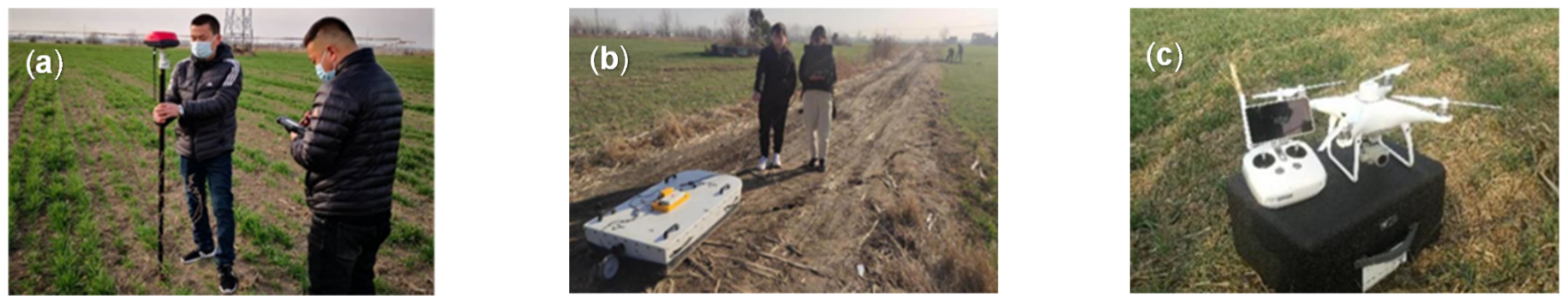
In this study, ground fissure development characteristics were investigated based on geo-radar, real-time kinematic (RTK) and Unmanned Aerial Vehicle (UAV) photography technologies. The development characteristics included the location (distribution), width and depth of ground fissure development, as shown in
Figure 6. The width of the ground fissure was measured by measuring tape, and the depth of the ground fissure was detected by geo-radar. Due to the different complexities of the surface environment above the working face, the investigation means of ground fissure distribution characteristics are different. The distribution of coal mining ground fissures on the WF
B was manually investigated (manual probing combined with RTK positioning). However, the distribution of ground fissures on the WF
A was obtained by manual investigation and UAV photography. This is because the surface environment of WF
A is simpler (only farmland). By contrast, WF
B has a more complex surface environment with the Longhe river (river bank), villages, orchards, farmland, etc. The fissure development characteristics in two working faces are described as follows:
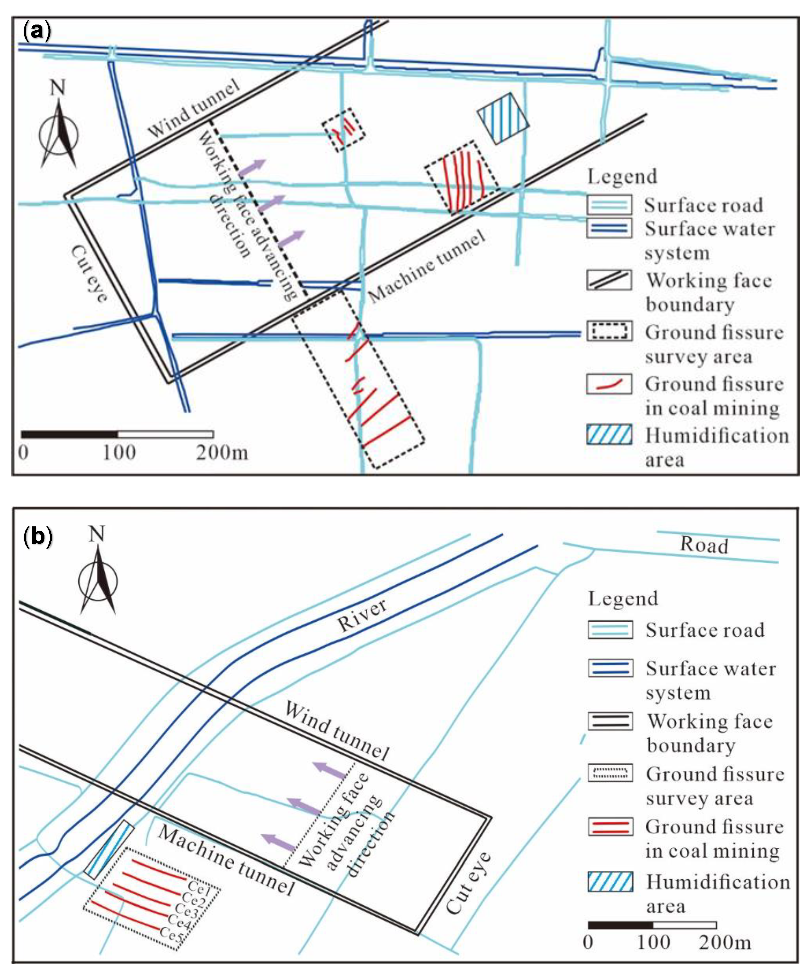
Figure 5.
Working faces and humidification areas. (a) WFA of Suntuan coal mine. (b) WFB of Zhuzhuang coal mine.
Figure 5.
Working faces and humidification areas. (a) WFA of Suntuan coal mine. (b) WFB of Zhuzhuang coal mine.
WFA: (1) Scale size: The width and depth of dynamic fissures were relatively small. The width of the dynamic fissures varied from a few millimeters to a few centimeters, and their depth varied from 1 to 4 m. The width of the marginal fissures varied from a few centimeters to several tens of centimeters, and their depth varied from 4 to 12 m. (2) Distribution law: Dynamic fissures were mainly developed in the area of about 100 m from the current mining position to the front, and the spacing of these fissures was 10~12 m. The marginal fissures were mainly developed in the area from 60 to 160 m outside the wind tunnel and machine tunnel. Generally, multiple marginal fissures were developed with a nearly parallel distribution, and their distribution spacing was 16~20 m.
WFB: (1) Scale size: Marginal fissures were significantly developed in the study area with a near east–west direction. The width of the marginal fissures varied from a few centimeters to several tens of centimeters, and their depth varied from 4 to 6 m. The dynamic fissure width varied from several millimeters to several centimeters and depth varied from 2 to 4 m. (2) Distribution law: Dynamic fissures were mainly developed in the area of about 110 m from the current mining position to the front, and the spacing of these fissures was 10~14 m. The marginal fissures were mainly developed in the area of 50~200 m outside the wind tunnel and machine tunnel. Generally, multiple marginal fissures were developed and distributed with a nearly parallel manner. In addition, the dam on the east side of the Longhe river at WFB was an earth-fill dam. The dam section is trapezoidal, the width of the dam top is 4 m and the slope of the dam is about 40°. At that time, there were a large number of fruit trees, shrubs and other vegetation on the top and slope of the dam.
Figure 6.
Investigation on fissure development characteristics of coal mining working faces. (a) RTK positioning. (b) Geo-radar detection. (c) UAV aerial photo.
Figure 6.
Investigation on fissure development characteristics of coal mining working faces. (a) RTK positioning. (b) Geo-radar detection. (c) UAV aerial photo.
As mentioned above, the underground mining of the selected two working faces led to the corresponding subsidence basins and ground fissures. The ground fissures both included dynamic fissures and marginal fissures. In order to study the prevention and control effects of the proposed humidification method, field experiments on the prevention and control of dynamic fissures and marginal fissures were carried out respectively.
4.2. Experimental Process
4.2.1. Humidification Area
In order to ensure that the soil in the humidification area was not deformed by the coal mining before the humidification was completed, the humidification area should be set at a certain distance along the working face advancement direction. Therefore, at the initial stage of the experiment, the location of the coal mining working face and its advancement speed (both approximately 4 m/d) must be fully considered in the determination of the humidification areas for two working faces. Additionally, the time required for the humidification process must also be considered. According to the different types of ground fissures to be prevented, the determination of every humidification area is described as follows:
WF
A: The humidification area was located approximately 150 m in front of the working face (horizontal distance), and the humidification area was a square plot with a side length of 40 m, as shown in
Figure 5a. Due to the control experiment being carried out for dynamic fissures, the humidification area was located above the working face (the proposed mined-out area).
WF
B: The humidification area was located approximately 150 m in front of the working face (horizontal distance), and it was a 90 m-long section of Longhe dam at the south of the mining boundary, as shown in
Figure 5b. The control experiment was carried out for marginal fissures, and the marginal fissures on the working face (south side) were mainly developed in the area of 50~200 m south from the mining boundary. The Longhe dam (50~140 m south from the mining boundary) and its two sides were selected as humidification areas.
4.2.2. Humidification Process
Firstly, based on RTK positioning and tape measurement, lime was used to delineate the humidification area of each working face. Then, high-lift pumps were used to pump water from nearby irrigation wells or surface ponds (rivers) to water the humidification area, as shown in
Figure 7. Humidification equipment mainly included: gasoline high-lift pumps, nylon hoses, etc. To determine the appropriate start time, it must be considered that the surface influence area of the mining working face was about 100 m from the working face’s current position to its front, and the normal advancing speed of WF
A or WF
B was about 4 m/d. When the mining position of the working face was about 130 m away from the designated humidification area (horizontal distance), the humidification was started by watering the area for about five days, which ensured that the humidification was finished before subsidence occurred. For the soil after humidification within the subsidence area, appropriate watering was carried out in the whole process of subsidence deformation (i.e., before the subsidence is stable) to keep its water content not lower than the plastic limit water content.
4.2.3. Humidification Effect
A soil moisture measure was used to obtain the water content distribution of the surface soil in the humidification area, which can control the humidification effect during the humidification process. Specifically, the water content distribution of the surface soil (10 cm deep) was measured in the humidification area during the humidification process. Then, the watering amount can be increased in time for the low water content soil, which can ensure uniform humidification in the humidification area of each working face. As shown in
Figure 8, the water content distribution of the surface soil in the WF
A humidification area before and after humidifying can be compared. The water content of the surface soil before humidifying is about 14% (the soil is dry due to less precipitation during the experiment), but the water content of the surface soil after humidifying is about 33%.
In order to obtain the humidification effect of each humidification area in detail, test pit profiles are excavated in the corresponding humidification area and non-humidification area (comparison) of each working face. Additionally, the soil water content was measured at different depths of burial in the profiles, as shown in
Figure 9. The test pits were 100 cm × 50 cm × 100 cm in length, width and depth, respectively. The water content of the soil was measured three times at the same depth and averaged. Each time the moisture was measured in the profile, the profile had to be excavated forward evenly 20 cm to avoid errors caused by human disturbance. In addition, while excavating the test pit, samples were taken on site using a standard ring knife for testing the physical and mechanical properties of the soil (see
Table 1 for the specific test results). In addition, while excavating the test pits, on-site samples were taken by the standard ring knife. They were used to test the physical and mechanical properties of the soils (see
Table 1 for specific test results).
Analysis of
Table 1 showed that, compared with the soil without humidification, the soil water content at a certain depth in the humidification area had increased. (1) WF
A: After continuous humidification, the soil water content in the upper part of the humidification area increased significantly, but the change in soil water content was small at the depth of 60 cm. That is, the humidification influence depth of the humidification area was about 60 cm. (2) WF
B: The water content of the soil at the depth of 0~80 cm in the humidification area increased significantly compared with the soil without humidification, and the soil water content was higher at shallower depths. In addition, with the increase in water content, the soil shear strength after humidification was significantly weakened.
It is necessary to clarify that the proposed humidification method was the uniform humidification of the soil layer in the surface subsidence area. That is, the humidification depth of the soil layer in the surface subsidence area was equal. In view of the fact that the surface land in the Huaibei plain mining area was mostly cultivated land, the coal mining ground fissures can lead to the seepage loss of cultivated land nutrients and the destruction of crop roots. Therefore, the humidification depth of humidification area in this field experiment was designed to be 60~80 cm.
4.2.4. Field Investigation
The field investigation was carried out for the humidification area and its adjacent non-humidification area (comparison) of each working face. For WFA, we carried out a field investigation of dynamic fissures, and for WFB, we carried out a field investigation of marginal fissures. Additionally, the depth and width information of ground fissures was collected every 1–2 days. The development characteristics of the corresponding coal mining ground fissures were investigated, and then the prevention and control effects of the humidification method on ground fissures were analyzed.
5. Experimental Results and Analyses
5.1. Prevention and Control of the Dynamic Fissures in WFA
With the continuous advance of the working face, the dynamic fissures in the humidification area were regularly developed. The development characteristics of the dynamic fissures were investigated for the humidification area and its adjacent non-humidification area (comparison). The results show that one obvious fissure (about 2 mm wide) was developed in the humidification area, while three obvious fissures (4–11 mm wide) were developed in the adjacent non-humidification area (comparison).
For further comparative analysis, two survey lines, L
1L
1′ and L
2L
2′, were set in the humidification and non-humidification areas (as shown in
Figure 10a), respectively. The ground-penetrating radar was used to detect the fissure spatial distribution in the humidification area, as well as the non-humidification area, and the results are shown in
Figure 10b,c. The radar detection results are consistent with the investigation results of surface dynamic fissures, as shown in
Figure 10c in the red line. In addition, it can be seen that the soil in the humidification area (line L
1L
1′) presented continuous subsidence deformation (see
Figure 10b). However, in the non-humidification area, the soil stratum (line L
2L
2′) presented discontinuous deformation with segmented subsidence (see
Figure 10c). Additionally, the soil stratum was divided into four segments. Due to the strong plasticity of soil with the high water content in the humidification area, the characteristic differences of dynamic fissures between humidification and non-humidification areas were formed. Specifically, compared with the non-humidification area, the number and width of dynamic fissures developed in the humidification area were significantly reduced. In conclusion, the humidification method had a significant effect on inhibiting the development of dynamic fissures.
5.2. Prevention and Control of Marginal Fissures in WFB
Before the humidification experiment, the marginal fissures development on the south side of WF
B was investigated. There were five obvious marginal fissures on the outside of the working face boundary, which were recorded as Ce1, Ce2, …, Ce5, in order, as shown in
Figure 5b. These five marginal fissures were all nearly parallel to the mining direction of the working face. Additionally, if Ce1, Ce2 and Ce3 develop along the existing direction, they would cross the humidification area.
After the humidification area was watered and humidified, the humidification and non-humidification areas (comparison) of WF
B were continuously observed, and the results were listed in
Table 2.
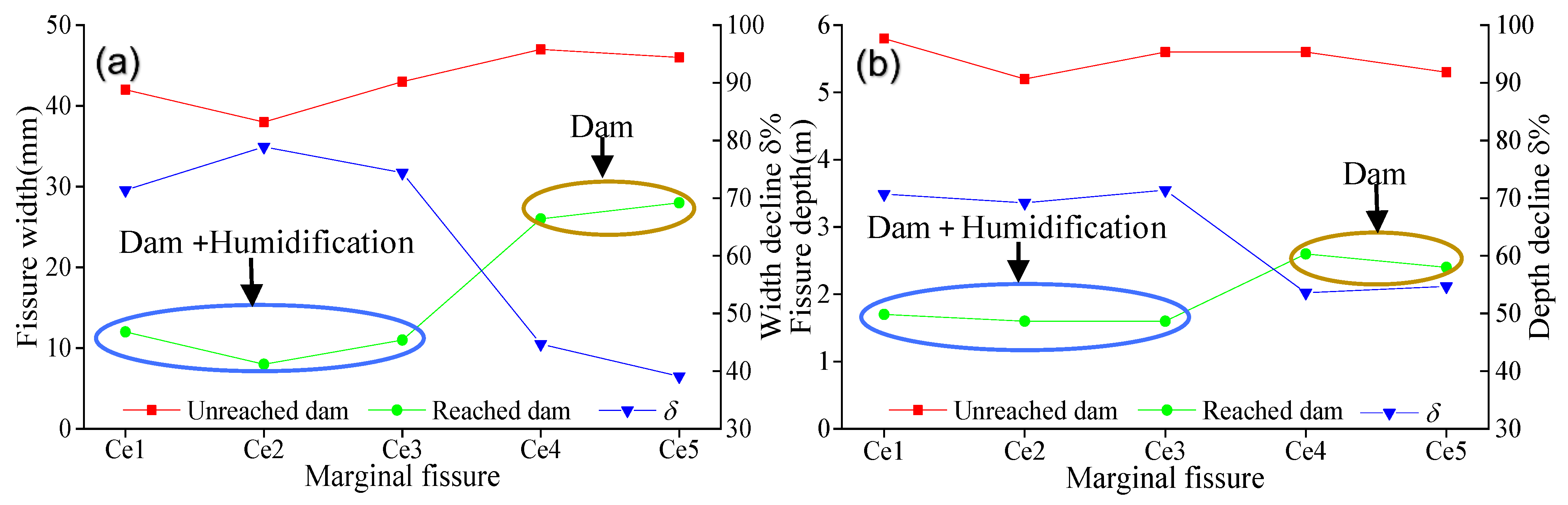
Figure 11 was drawn according to
Table 2, and the decreased degree in fissure width (depth) can be described via the index δ, which was the ratio of the fissure width (depth) decrease after reaching the dam from the fissure width (depth) before reaching the dam. The results show that the five marginal fissures continued to develop along the advancement direction of coal mining activities and eventually affected the dam. When reaching the dam on the east side of the Longhe river, the development degree of all five marginal fissures weakened. Compared with marginal fissures Ce4 and Ce5, the development degree of Ce1~Ce3 weakened more obviously at the dam after humidification.
As mentioned above, the development degree of the five marginal fissures at the dam better indicated that the humidification method had an obvious preventive effect on the marginal fissures of the Longhe river dam. However, the development degree of all five marginal fissures weakened when they reached the dam. Especially, the development degrees of Ce4 and Ce5 that were not affected by the humidification method at the dam were also weakened. The main reason was that compared with the soil before reaching the dam, the physical and mechanical properties of the soil at the dam foundation and the dam body were different.
6. Discussion
(1) The proposed humidification method is the uniform humidification of the soil layer within the surface subsidence area (the same humidification depth), which may cause low humidification efficiency and waste of humidification water. This is because the deformation depth of overlying strata caused by the underground mined-out area is not uniform within the coal mining subsidence area. As shown in
Figure 12, the rock–soil mass which is deformed (displacement) by the mined-out area can be considered as a whole, and its distribution area is called the rock–soil mass deformation zone [
34]. The idea of obtaining the lower boundary of the rock–soil mass deformation zone is as follows: (a) In the tensile region of the proposed mining subsidence basin, several deformation monitoring boreholes can be set up at a certain distance along the vertical direction of the working face advancement direction. (b) Based on clinometer, optical fiber deformation monitoring and other technologies, the whole deformation process monitoring of boreholes, “stability–deformation–stability”, can be carried out. (c) Based on the low of every borehole deformation, the lower boundary of rock–soil mass deformation zone can be analyzed and obtained.
The mining practice indicates that for any point (P1) in the tensile region, as the distance (l) between the point (P1) and the mined-out area boundary increases, the depth (h) of the deformation zone boundary at P1 position decreases. Therefore, for the humidification of the soil layer in the subsidence area compared with the middle region (CC′) of the subsidence basin, the humidification depth (h) in the tensile region (AC, A′C′) can be appropriately reduced with the increase in the horizontal distance (l) from the mined-out area boundary, which can reduce humidification water consumption and improve humidification efficiency. In conclusion, during the implementation process of the humidification method proposed in this study, the maximum humidification depth of the soil layer at any point (such as P1) within the subsidence area does not exceed the lower boundary of the rock–soil mass deformation zone.
(2) The influence of humidification depth on the prevention and control effects of coal mining ground fissures needs to be further studied. Considering that ground fissures can lead to seepage loss of cultivated land nutrients and tension fractures of crop roots, the field experiments carried out in this study were conducted for uniform humidification of the soil layer within the subsidence area, and the humidification depth was set to 0.6–0.8 m. However, for the dynamic fissures in the middle region of the subsidence basin, different values of humidification depth (such as 1.0 m and 1.2 m) can be further considered to explore the correlation between humidification depth and dynamic fissure control effects.
(3) The influence of humidification degree on the prevention and control effect of coal mining ground fissures needs to be further studied. In order to study the prevention and control effect of ground fissures, the soil layer within the subsidence area was humidified to the plastic state in this study. However, it is urgent to carry out the correlation analyses between the humidification degree (different water content between liquid and plastic limits) and the prevention and control effect of ground fissures. Finally, the humidification cost and prevention and control effect can be comprehensively considered to carry out the optimization design study of the humidification method.
Figure 12.
The sketch of coal mining subsidence basin and its rock–soil mass deformation zone.
Figure 12.
The sketch of coal mining subsidence basin and its rock–soil mass deformation zone.
7. Conclusions
(1) The model experiment showed that the higher the water content of plastic soil samples, the lower the development degree of surface fissures.
(2) Based on the humidification method, the field prevention and control experiments of dynamic fissures and marginal fissures in WFA and WFB were carried out. The results show that the humidification method can significantly reduce the development degree of these two types of ground fissures.
(3) Although the proposed humidification method can effectively reduce the ground fissure development degree in plain mining area to a certain extent, the area of humidification depth and humidification degree still need further research.
Author Contributions
Conceptualization, J.Y.; Writing—original draft, Y.C.; Writing—review & editing, H.L., H.H. (He Huang), Y.F. and H.H. (Houxu Huang). All authors have read and agreed to the published version of the manuscript.
Funding
This paper is supported by the Science and Technology Project of Department of Natural Resources of Anhui Province (2020-K-6), the Natural Science Foundation of Anhui Province (2108085QD169 and 2008085QE219), the Provincial Natural Science Research Project of Colleges and Universities of Anhui Province (No. KJ2019A0741) and the Doctoral initial funding project of Anhui Jianzhu University (2018QD26 and 2019QDZ52).
Institutional Review Board Statement
Not applicable.
Informed Consent Statement
Not applicable.
Data Availability Statement
Not applicable.
Conflicts of Interest
The authors declare no conflict of interest.
References
- Karacan, C.Ö. Forecasting gob gas venthole production performances using intelligent computing methods for optimum methane control in longwall coal mines. Int. J. Coal Geol. 2009, 79, 131–144. [Google Scholar] [CrossRef]
- Wempen, J.M. Application of DInSAR for short period monitoring of initial subsidence due to longwall mining in the mountain west United States. Int. J. Min. Sci. Technol. 2020, 30, 33–37. [Google Scholar] [CrossRef]
- Bell, F.G.; Stacey, T.R.; Genske, D.D. Mining subsidence and its effect in the environment: Some differing examples. Environ. Geol. 2000, 40, 135–152. [Google Scholar] [CrossRef]
- Dai, H.Y.; Wang, J.Z.; Cai, M.F.; Wu, L.X.; Guo, Z.Z. Seam dip angle based mining subsidence model and its application. Int. J. Rock Mech. Min. Sci. 2002, 39, 115–123. [Google Scholar]
- Liu, H.; Deng, K.Z.; Zhu, X.J.; Jiang, C.L. Effects of mining speed on the developmental features of mining-induced ground fissures. Bull. Eng. Geol. Environ. 2019, 78, 6297–6309. [Google Scholar] [CrossRef]
- Mohammady, M.; Pourghasemi, H.R.; Amiri, M. Assessment of land subsidence susceptibility in Semnan plain (Iran): A comparison of support vector machine and weights of evidence data mining algorithms. Nat. Hazards 2019, 99, 951–971. [Google Scholar] [CrossRef]
- Bagheri-Gavkosh, M.; Hosseini, S.M.; Ataie-Ashtiani, B.; Sohani, Y.; Ebrahimian, H.; Morovat, F.; Ashrafi, S. Land subsidence: A global challenge. Sci. Total Environ. 2021, 778, 146193. [Google Scholar] [CrossRef]
- Donnelly, L.J.; De La Cruz, H.; Asmar, I.; Zapata, O.; Perez, J.D. The monitoring and prediction of mining subsidence in the Amaga, Angelopolis, Venecia and Bolombolo Regions, Antioquia, Colombia. Eng. Geol. 2001, 59, 103–114. [Google Scholar] [CrossRef]
- Lamich, D.; Marschalko, M.; Yilmaz, I. Subsidence measurements in roads and implementation in land use plan optimisation in areas affected by deep coal mining. Environ. Earth Sci. 2016, 75, 69. [Google Scholar] [CrossRef]
- Cheng, G.W.; Ma, T.H.; Tang, C.A.; Liu, H.Y.; Wang, S.J. A zoning model for coal mining-induced strata movement based on microseismic monitoring. Int. J. Rock Mech. Min. Sci. 2017, 94, 123–138. [Google Scholar] [CrossRef]
- Hu, Z.Q.; Wang, X.J.; He, A.M. Distribution characteristic and development rules of ground fissures due to coal mining in windy and sandy region. J. China Coal Soc. 2014, 39, 11–18. [Google Scholar] [CrossRef]
- Meng, Z.P.; Shi, X.C.; Li, G.Q. Deformation, failure and permeability of coal-bearing strata during longwall mining. Eng. Geol. 2016, 208, 69–80. [Google Scholar] [CrossRef]
- Ye, Q.; Wang, G.; Jia, Z.Z.; Zheng, C.S.; Wang, W.J. Similarity simulation of mining-crack-evolution characteristics of overburden strata in deep coal mining with large dip. J. Pet. Sci. Eng. 2018, 165, 477–487. [Google Scholar] [CrossRef] [Green Version]
- Wu, W.D.; Bai, J.B.; Wang, X.Y.; Zhu, Z.J.; Yan, S. Field investigation of fractures evolution in overlying strata caused by extraction of the jurassic and carboniferous coal seams and its application: Case study. Int. J. Coal Geol. 2019, 208, 12–23. [Google Scholar] [CrossRef]
- Zuo, J.P.; Peng, S.P.; Li, Y.J.; Chen, Z.H.; Xie, H.P. Investigation of karst collapse based on 3-D seismic technique and DDA method at Xieqiao coal mine, China. Int. J. Coal Geol. 2009, 78, 276–287. [Google Scholar] [CrossRef]
- Unlu, T.; Akcin, H.; Yilmaz, O. An integrated approach for the prediction of subsidence for coal mining basins. Eng. Geol. 2013, 166, 186–203. [Google Scholar] [CrossRef]
- Yang, X.L.; Wen, G.C.; Dai, L.C.; Sun, H.T.; Li, X.L. Ground subsidence and surface cracks evolution from shallow-buried close-distance multi-seam mining: A case study in Bulianta coal mine. Rock Mech. Rock Eng. 2019, 52, 2835–2852. [Google Scholar] [CrossRef]
- Singh, K.B.; Singh, T.N. Ground movements over longwall workings in the Kamptee coalfield, India. Eng. Geol. 1998, 50, 125–139. [Google Scholar] [CrossRef]
- Jung, H.C.; Kim, S.W.; Jung, H.S.; Min, K.D.; Won, J.S. Satellite observation of coal mining subsidence by persistent scatterer analysis. Eng. Geol. 2007, 92, 1–13. [Google Scholar] [CrossRef]
- Ghabraie, B.; Ren, G.; Smith, J.V. Characterising the multi-seam subsidence due to varying mining configuration, insights from physical modelling. Int. J. Rock Mech. Min. Sci. 2017, 93, 269–279. [Google Scholar] [CrossRef]
- Liu, H.; Lei, S.G.; Deng, K.Z.; Yu, Y.; Wang, Y.X. Research on ground fissure treatment filling with super-high-water material. J. China Coal Soc. 2014, 39, 72–77. [Google Scholar]
- Bi, Y.L.; Zhang, J.; Song, Z.H.; Wang, Z.G.; Qiu, L.; Hu, J.J.; Gong, Y.L. Arbuscular mycorrhizal fungi alleviate root damage stress induced by simulated coal mining subsidence ground fissures. Sci. Total Environ. 2019, 652, 398–405. [Google Scholar] [CrossRef] [PubMed]
- Rahmati, O.; Golkarian, A.; Biggs, T.; Keesstra, S.; Mohammadi, F.; Daliakopoulos, I.N. Land subsidence hazard modeling: Machine learning to identify predictors and the role of human activities. J. Environ. Manag. 2019, 236, 466–480. [Google Scholar] [CrossRef] [PubMed]
- Wang, R.; Bai, J.B.; Yan, S.; Chang, Z.G.; Wang, X.Y. An innovative approach to theoretical analysis of partitioned width & stability of strip pillar in strip mining. Int. J. Rock Mech. Min. Sci. 2020, 129, 104301. [Google Scholar] [CrossRef]
- Du, W.G.; Chai, J.; Zhang, D.D.; Lei, W.L. The study of water-resistant key strata stability detected by optic fiber sensing in shallow-buried coal seam. Int. J. Rock Mech. Min. Sci. 2021, 141, 104604. [Google Scholar] [CrossRef]
- Wang, F.; Jiang, B.Y.; Chen, S.J.; Ren, M.Z. Surface collapse control under thick unconsolidated layers by backfilling strip mining in coal mines. Int. J. Rock Mech. Min. Sci. 2019, 113, 268–277. [Google Scholar] [CrossRef]
- Zhang, D.S.; Fan, G.W.; Ma, L.Q.; Wang, X.F. Aquifer protection during longwall mining of shallow coal seams: A case study in the Shendong Coalfield of China. Int. J. Coal Geol. 2011, 86, 190–196. [Google Scholar] [CrossRef]
- Xuan, D.Y.; Xu, J.L.; Wang, B.L.; Teng, H. Borehole investigation of the effectiveness of grout injection technology on coal mine subsidence control. Rock Mech. Rock Eng. 2015, 48, 2435–2445. [Google Scholar] [CrossRef]
- Zhu, X.J.; Guo, G.L.; Liu, H.; Yang, X.Y. Surface subsidence prediction method of backfill-strip mining in coal mining. Bull. Eng. Geol. Environ. 2019, 78, 6235–6248. [Google Scholar] [CrossRef]
- Wu, K.; Hu, Z.Q.; Chang, J.; Ge, J.X. Distribution law of ground crack induced by coal mining. J. China Univ. Min. Technol. 1997, 26, 56–59. [Google Scholar]
- Kang, J.R. Analysis of effect of fissures caused by underground mining on ground movement and deformation. Chin. J. Rock Mech. Eng. 2008, 27, 59–64. [Google Scholar]
- Zhou, D.W.; Wu, K.; Bai, Z.H.; Hu, Z.Q.; Li, L.; Xu, Y.K.; Diao, X.P. Formation and development mechanism of ground crack caused by coal mining: Effects of overlying key strata. Bull. Eng. Geol. Environ. 2019, 78, 1025–1044. [Google Scholar] [CrossRef]
- Erguler, Z.A.; Ulusay, R. Water-induced variations in mechanical properties of clay-bearing rocks. Int. J. Rock Mech. Min. Sci. 2009, 46, 355–370. [Google Scholar] [CrossRef]
- Sun, Y.J.; Zuo, J.P.; Karakus, M.; Wang, J.T. Investigation of movement and damage of integral overburden during shallow coal seam mining. Int. J. Rock Mech. Min. Sci. 2019, 117, 63–75. [Google Scholar] [CrossRef]
| Publisher’s Note: MDPI stays neutral with regard to jurisdictional claims in published maps and institutional affiliations. |
© 2022 by the authors. Licensee MDPI, Basel, Switzerland. This article is an open access article distributed under the terms and conditions of the Creative Commons Attribution (CC BY) license (https://creativecommons.org/licenses/by/4.0/).


