Article

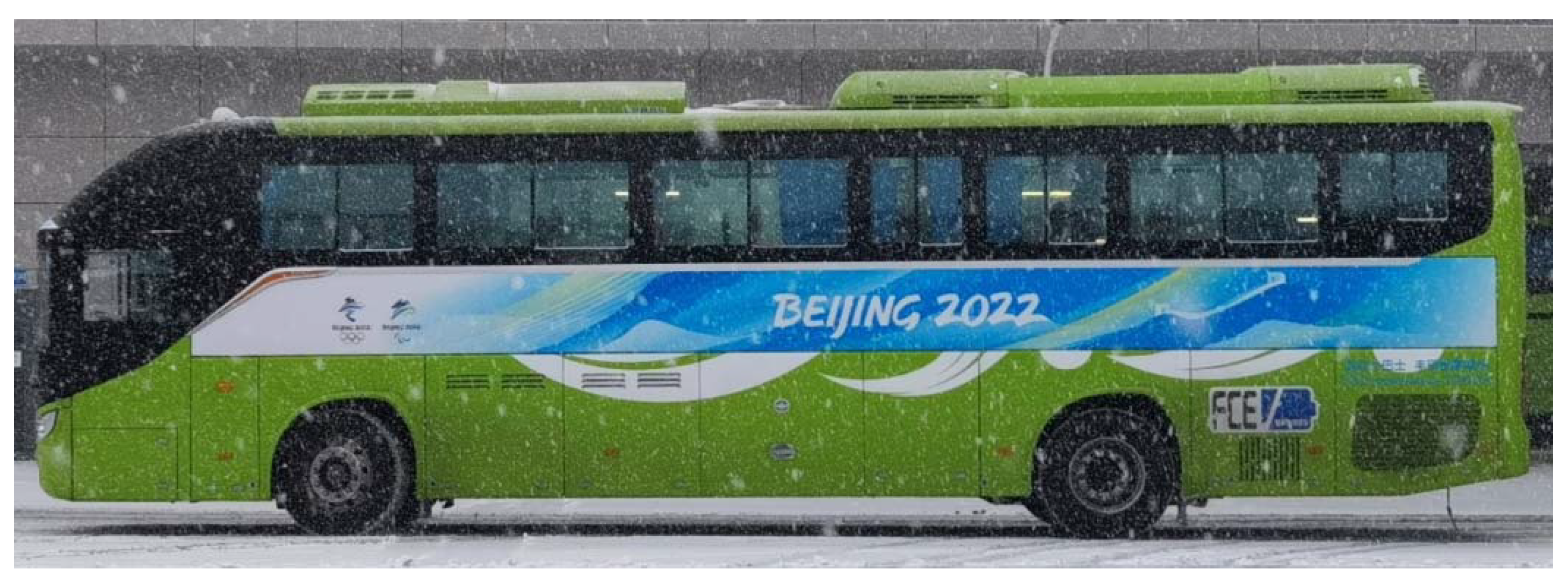
Powertrain Design and Energy Management Strategy Optimization for a Fuel Cell Electric Intercity Coach in an Extremely Cold Mountain Area

1
School of Mechanical Engineering, Beijing Institute of Technology, Beijing 100081, China
2
Technical Research Institute, Beijing Foton AUV New Energy Bus Co., Ltd., Beijing 102200, China
3
School of Mathematic and Statistics, Liaoning University, Shenyang 110036, China
*
Author to whom correspondence should be addressed.
Sustainability 2022, 14(18), 11253; https://doi.org/10.3390/su141811253
Submission received: 16 August 2022 / Revised: 4 September 2022 / Accepted: 6 September 2022 / Published: 8 September 2022
(This article belongs to the Special Issue Hybrid Energy System in Electric Vehicles)

Abstract

:
Facing the challenge that the single-motor electric drive powertrain cannot meet the continuous uphill requirements in the cold mountainous area of the 2022 Beijing Winter Olympics, the manuscript adopted a dual-motor coupling technology. Then, according to the operating characteristics and performance indicators of the fuel cell (FC)–traction battery hybrid power system, the structure design and parameter matching of the vehicle power system architecture were carried out to improve the vehicle’s dynamic performance. Furthermore, considering the extremely cold conditions in the Winter Olympics competition area and the poor low-temperature tolerance of core components of fuel cell electric vehicles (FCEV) under extremely cold conditions, such as the reduced capacity and service life of traction batteries caused by the rapid deterioration of charging and discharging characteristics, the manuscript proposed a fuzzy logic control-based energy management strategy (EMS) optimization method for the proton exchange membrane fuel cell (PEMFC), to reduce the power fluctuation, hydrogen consumption and battery charging/discharging times, and at the same time, to ensure the hybrid power system meets the varying demand under different conditions. In addition, the performance of the proposed approach was investigated and validated in an intercity coach in real-world driving conditions. The experimental results show that the proposed powertrain with an optimal control strategy successfully alleviated the fluctuation of vehicle power demand, reduced the battery charging/discharging times of traction battery, and improved the energy efficiency by 20.7%. The research results of this manuscript are of great significance for the future promotion and application of fuel cell electric coaches in all climate environments, especially in an extremely cold mountain area.

1. Introduction

With the deteriorating global environmental problems and the tough carbon neutrality goals, non-polluting and zero-emission hydrogen energy has been paid increasingly more attention in recent years, among which hydrogen fuel cell electric vehicles (FCEV) have become vital to solving this problem. Fuel cells with high energy density are an ideal energy supply system that can be combined with lithium batteries to generate the energy required for FCEVs [1,2]. Lithium traction batteries in FCEVs can provide fast dynamic loads, absorb braking feedback energy, reduce fuel cell (FC) power supply load and power fluctuations, and prolong system life [3,4,5].
However, hydrogen FCEVs are still in the initial stage of commercial application [6,7,8], and market promotion still faces many challenges [9,10]. The cold temperature tolerance of critical components of FCEVs deteriorate under low-temperature conditions [11,12]; in particular, the charging and discharging characteristics of the power batteries decline [13,14]. The capacity and service life are also reduced [15], which might lead to a significant decrease in vehicle driving range and vehicle power performance [6,16].
Over the past few years, to develop a fuel cell electric intercity coach suitable for the 2022 Beijing Winter Olympics, the R&D team has focused on overcoming the start–stop problem of the vehicle in extremely cold mountainous areas with high steep slopes and continuous turns to ensure the dynamic performance of the vehicle [16,17]. For this kind of FCEV, in all climate and complex regional application scenarios, the team completed the matching design of the vehicle power system architecture in a targeted manner, and formulated appropriate energy management strategies (EMSs). To maximize the utilization of the two energy sources, the strategy ensures that the lithium traction battery can provide a fast dynamic load, absorb regenerative braking energy, and reduce the power load and power fluctuation of the FC, then improves the efficiency of both batteries, thereby improving the durability and economy of the vehicle.
EMSs are generally classified as rule-based or optimal [18]. Rule-based strategies are normally designed using engineering hunches and experience to perform power allocation by following a map or set of rules [19]. Optimal strategies, derived from the optimal control theory, always involve minimizing some cost function, and then using mathematical optimization means, such as the Pontryagin minimum principle, dynamic programming, and nonlinear programming [20,21]. Optimal strategies were usually used to diminish hydrogen fuel consumption, and to increase FC lifetime and driving range. In contrast, rule-based approaches were generally utilized to determine the involvement of the energy storage system systems all the time, and it was the most normal method to realize real-time management in FCEV applications [22]. Currently, the most common rule-based EMSs for FCEVs mainly include the state machine control strategy equivalent consumption minimization strategy and the fuzzy logic control strategy [23,24]. Ettihir et al. [25] put forward an optimal strategy based on the Pontryagin minimum principle, which used a PI controller to adjust the co-state value and keep the battery state of charge (SOC) within a feasible range. Fletcher et al. [26] created a multidimensional lookup table using random dynamic programming, which could be used for airborne applications. Mehroze et al. [27] compared these three common strategies in the field of hydrogen consumption and analyzed the connection between driving performances and hydrogen consumption. Geng et al. [28] suggested an EMS for vehicles based on the fuzzy logic strategy. Guo et al. [29] developed a model prognostic control structure to integrate speed into energy management. Hu et al. [30] offered a concept of predictive model control to lengthen the lifetime of FCEVs. Ravey et al. [31] projected an EMS in line with fuzzy logic and optimized it with a genetic algorithm. This method protrudes the potential of an optimized rule-based strategy. However, among these strategies, the lifetime of FCs was usually ignored. Due to previous research, the vehicle power demand and traction battery SOC were mainly selected as the input variables in light of the driving conditions, and the FC output power as the output variable. Although these EMSs could ensure the stability of the traction battery, the following performance of the FC with the motor power output lagged significantly, and the overall hydrogen fuel economy was low as well.
Therefore, on this basis, the manuscript proposed an optimized EMS of an FC electric intercity coach in line with fuzzy logic control, which took the difference value between the power demand of the whole vehicle and the power generated by the FC generator at the current speed, took the SOC of the traction battery and the motor speed at the current speed as the input variables, and took the power command of the FC system as the output variable. Thus, the power output fluctuation of the traction battery and FC system could be controlled more accurately and sensitively. In the end, the performance evaluation of the whole vehicle was completed through the operation of the actual FC electric intercity coach under the C-WTVC standard cycle and compared with EMSs which are common in the current market.

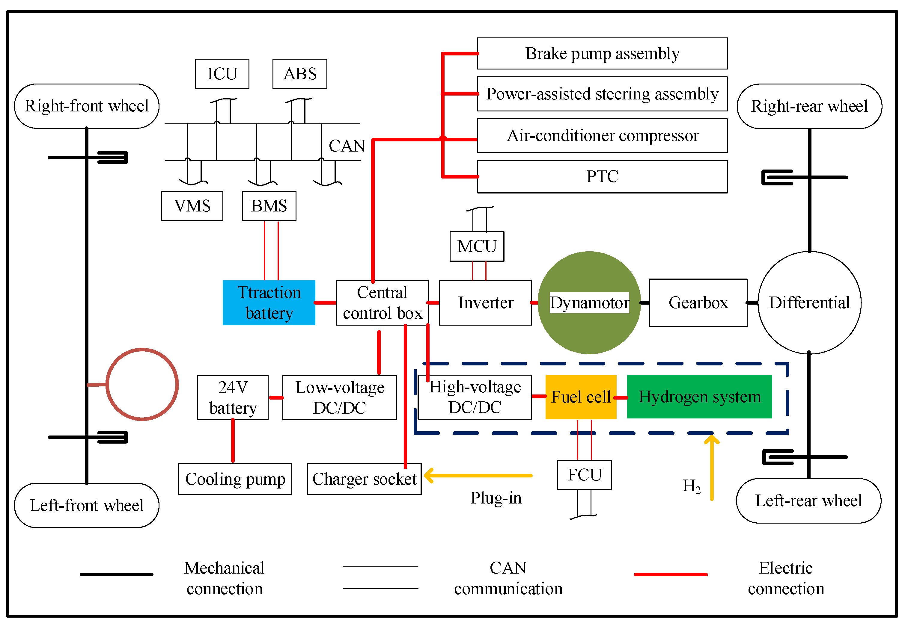
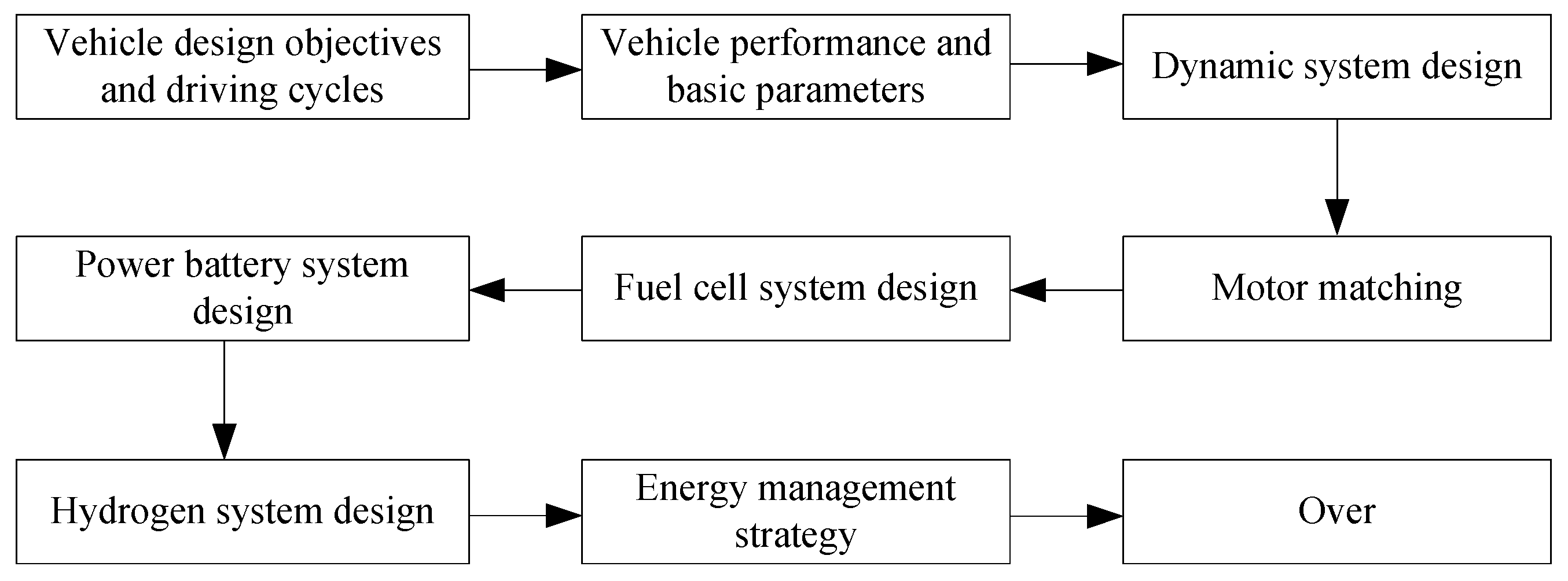
2. Integrated Design of Powertrain System

In hydrogen FCEVs, the drive motor, FC, and traction battery are the core components of the power system. When designing the hydrogen FC electric intercity coach, its power system structure needed to be selected according to market demand and the current technical level. The target vehicle proposed in this manuscript was a 16.4-ton commercial coach. The requirements of vehicle parameters and performance indicators are shown in Table 1, and the power mechanism of the vehicle is shown in Figure 1.

2.1. Selection and Matching

The parameter matching of core powertrain components of the FC electric intercity coach was mainly based on the power balance equation of the vehicle operation. It took the peak power required by the vehicle’s performance indicators, including maximum speed, maximum grade ability, and acceleration time, as the selection basis. The specific selection matching process is shown in Figure 2, and the longitudinal dynamics of the vehicle are depicted in Figure 3. The resistance acting on the vehicle was mainly related to the rolling friction Froll, the road slope α, and the aerodynamic resistance Fdrag. The parameter names are shown in Nomenclature. Due to the large mass mg of the coach, the force mgsinα could not be ignored as is usually assumed for light-duty vehicles.

2.1.1. Drive Motor System

For the drive motor of the vehicle, generally, when the speed of the motor was lower than the rated speed, the motor worked in the state of constant torque; when the speed of the motor was higher than the rated speed, the motor worked in the state of constant power. Therefore, when matching the parameters of the drive motor, the parameters that should be determined include the rated speed, peak speed, peak power, and peak torque of the drive motor.
The peak speed Nm and rated speed Nr of the drive motor were calculated by Equations (1) and (2), respectively.
N m = v m r 0 . 377 i
N r = N m β
The peak power Pm of the drive motor was calculated according to the energy balance Equation (3). In general, Pm usually included three parts: the value P1 calculated by maximum speed, the value P2 calculated by maximum climbing, and the value P3 calculated by acceleration time from 0 to 50 km/h. They were determined by Equations (4)–(6), respectively.
P m = 1 η t ( mgf 3600 v + mgi 3600 v + C d A 76140 v 3 + δ m 3600 v dv dt )
P 1 = 1 η t ( mgf 3600 v m + C d A 76140 v m 3 )
P 2 = 1 η t ( mgfcos α 3600 v + mgisin α 3600 v + C d A 76140 v 3 )
t = 1 3 . 6 ( 0 v 0 δ m 3600 P 3 η t v 0 - mgf - C d A 21.15 v 2 dv + v 0 v δ m 3600 P 3 η t v - mgf - C d A 21 . 15 v 2 dv )
Constraints:
Pm ≥ max{P1, P2, P3}
The peak torque Tm of the drive motor was calculated by Equations (8) and (9).
T r = 9550 P r N r
T m = λ T r
Aiming at the problem that the single-motor drive system could not meet the continuous uphill slope in the cold mountainous area of the 2022 Beijing Winter Olympics, the manuscript adopted the dual-motor coaxial propulsion (DMCP) system because it had multiple working modes to adapt to the complex working environment, to meet the particular application scenarios of the 2022 Beijing Winter Olympics [32,33]. The system greatly simplifies uninterrupted gear shifting. The basic parameters of the drive motor are shown in Table 2, and the configuration of the DMCP system is shown in Figure 4, which was chiefly composed of a traction motor (TM) and an auxiliary motor (AM). To reduce the torsional vibration of the system, the motor power shaft and the system output shaft were arranged in the same straight line. In this way, it was similar to the traditional single-motor system, which ensured that there was no power interruption during the vehicle’s operation, especially during the shifting process.

2.1.2. FC System

The hydrogen FC system should meet the power demand of FCEVs at the expected speed. In this manuscript, the common speed of the intercity coach was 40–60 km/h, and the power output Pfc of the FC system was calculated by Equation (10).
P fc = 1 3600 η motor η t η DC mgfv + C d A 21 . 15 v 3 + P aux

2.1.3. Traction Battery System

The traction battery provided instantaneous power upon driving the vehicle, which played the role of “peak cut” to make the FC system work as stably and efficiently as possible and reduce the fluctuations of its power output. To meet the power requirement of the vehicle in real time, the hydrogen FC intercity coach should drive at least 100 km at the speed of 40 km/h under a pure electric state. At this time, the power output Pb of the traction battery was expressed in the following equation.
P b = 1 3600 η motor η t η bat mgfv + C d A 21 . 15 v 3
The energy required for the process, Eb:
E b = P b · t = P b · S v
The relationship between the power battery capacity C and the total electric energy consumption:
C = 1000 E b U 0

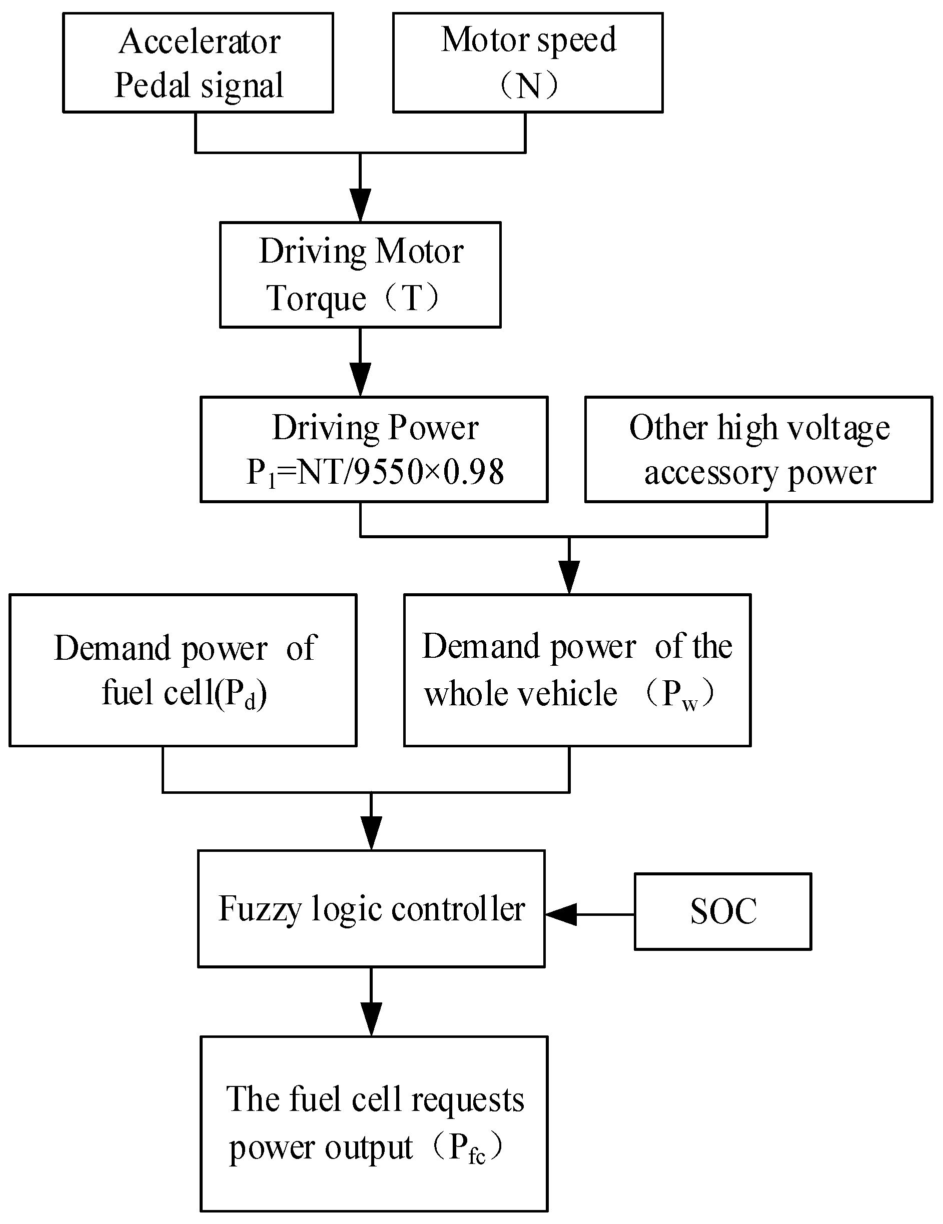
3. The Energy Management Strategy

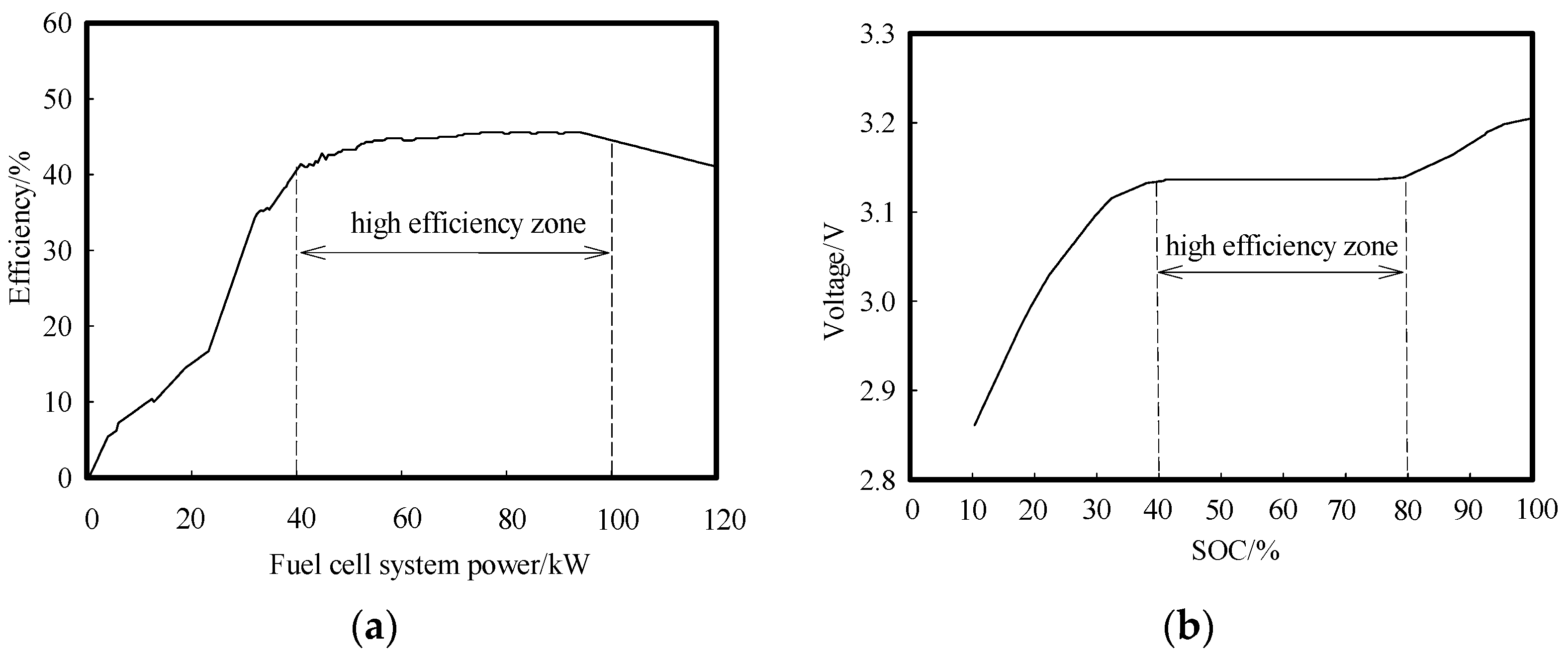
3.1. Effective Working Range of the FC and Traction Battery

The efficient working range of the FC system and the traction battery SOC should be determined before formulating the EMS. For the FC system, the effective working interval was mainly evaluated according to its working efficiency, and the power efficiency curve of the selected FC system is shown in Figure 5a. For the traction battery, the practical working interval was determined to realize the purpose of shallow charge and shallow discharge as much as possible, to extend its service life. The voltage characteristic curve for a single battery is shown in Figure 5b, wherein the voltage axis represents an efficiency axis.
In Figure 5a, the FC maintained a high working efficiency in the range of 40–100 KW, and then decreased slowly. To ensure that the FC operated in the high-efficiency range as much as possible, the traction battery needed to realize the function of “cut the peak and fill the gap” when the demand power of the vehicle was higher than 100 KW or less than 40 KW. Figure 5b shows that the voltage maintains a stable output when the SOC of the traction battery was in the range of 40~80%. When the SOC of the traction battery was too high or too low, the voltage was too high or too low as well, which may affect the performance of the battery. In this manuscript, the expected value SOC of the traction battery was chosen as the average of 40% and 80%, that is, SOC* = 60%.

3.2. Control Method

According to the power mechanism of the vehicle shown in Figure 1, the FC system directly met the power demand of the drive motor as far as possible, according to the requested power that was sent to the drive motor by the whole vehicle. The traction battery mainly recovered the braking energy. What is more, when the FC system could not meet the power demand for the driving motor, the traction battery supplemented the energy for the requested power of the driving motor at this time. That is, the traction battery achieves the aim of “peak load shifting”. This power mechanism could reduce the power fluctuation of FCs and traction batteries, improve energy utilization, and extend the service life of power systems. The basic concept of optimized EMSs on the basis of fuzzy logic control is shown in Figure 6. Firstly, the required torque Tr of the whole vehicle was calculated and the power demand Pw of the whole vehicle was obtained from the torque and motor speed according to the selected operating conditions and vehicle speed. Then, the fuzzy logic controller adjusted the power output Pfc of the FC system according to the SOC of the traction battery and the real-time power demand Pd of the whole vehicle.
Fuzzy logic control included three main parts: input variable, fuzzy logic controller, and output variable. Its working principle is shown in Figure 7. The power difference ΔP, the SOC of the traction battery, and the motor speed n were selected as three inputs in the fuzzy logic controller. ΔP was the power difference between the vehicle’s power demand and the FC system’s requested power at the real-time speed. ΔP ∈ [−1, 1], SOC ∈ [0, 1], n ∈ [0, 1]. The membership function of ΔP was defined as more negative (MN), negative (N), ZERO, positive (P), or more positive (MP). The membership function of the SOC was defined as {lower, low, optimal, high, higher}. The membership function of n was defined as {low, high}. (2) Rule base: Table 3 shows the rule base of the fuzzy logic controller, which was a typical type of the A+B+C→D (if A, B, and C, then D) mode, where A denoted the fuzzy sets of n, B denoted the fuzzy sets of SOC, C denoted the fuzzy sets of ΔP, and D denoted the fuzzy sets of the power output Pfc of the FC system. (3) Fuzzy reasoning and anti-fuzzification: fuzzy logic calculation was performed using the Mamdani method. To ensure the control accuracy and calculation speed, the fuzzy controller always used the weighted average method for defuzzification, which was extensively applied in industrial control.

4. Experimental Results and Discussion

4.1. Normalized World Transient Vehicle Cycle

The actual intercity bus designed in this study is shown in Figure 8. Firstly, the speed curve of the vehicle was drawn according to 1800s World Transient Vehicle Cycle (C-WTVC) conditions, with the sampling time as 1s, as shown in Figure 9. Under this condition, the performance of the drive system, FC, and traction battery before and after the optimization of the EMS was compared. Then, the optimized EMS was used for actual operation on low-temperature mountain roads, and the relevant data on the vehicle’s climbing ability and hydrogen consumption economy were obtained.

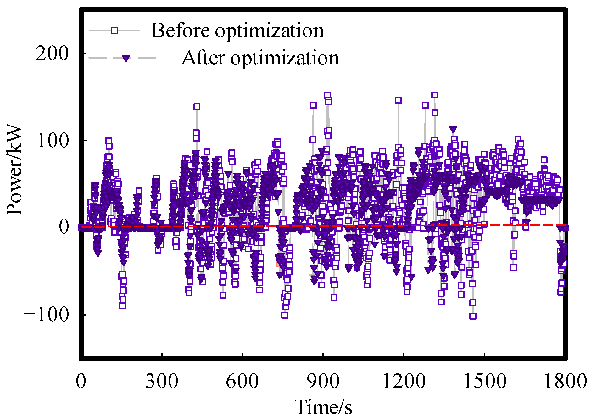
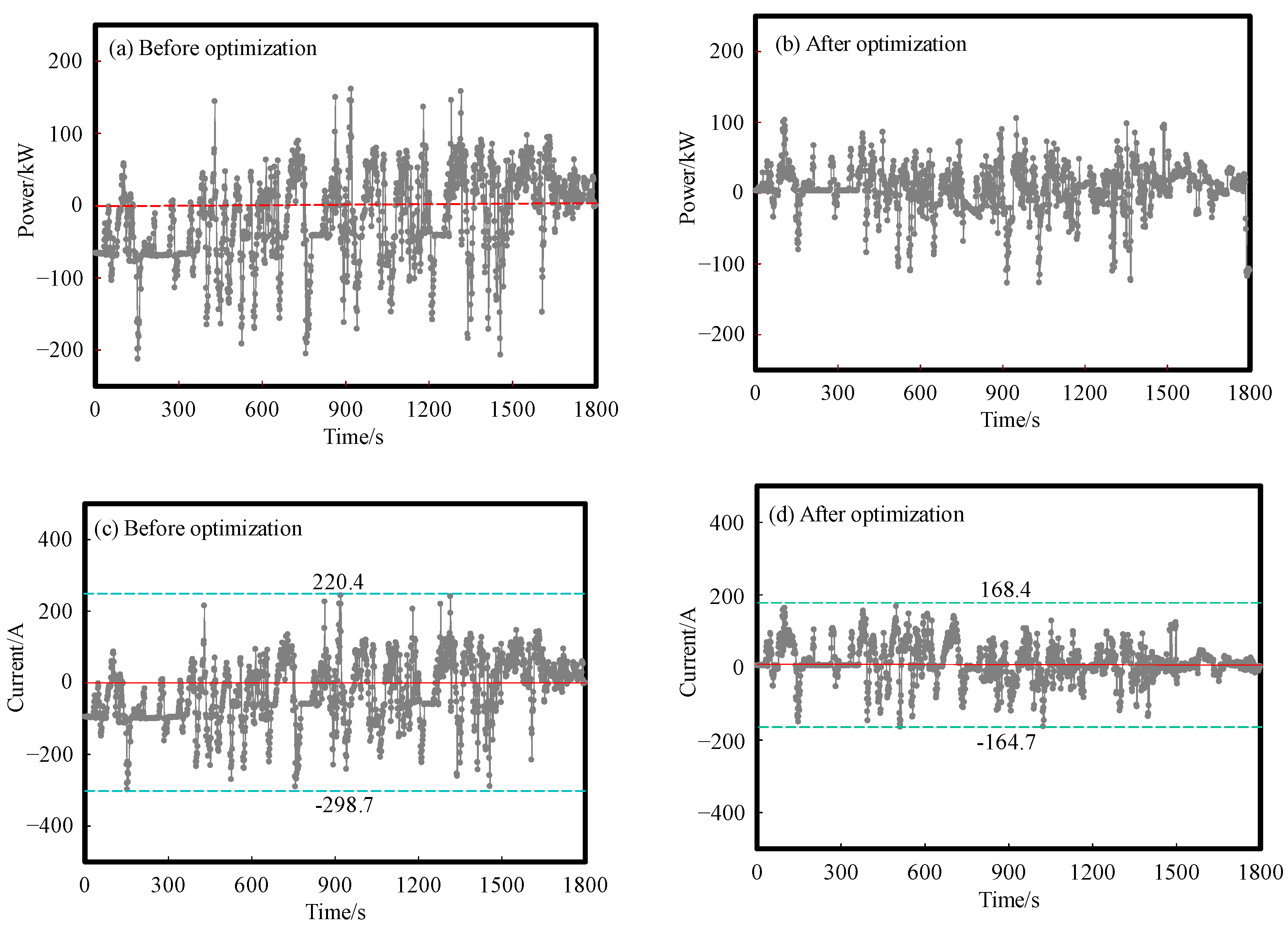
4.1.1. Vehicle Power Demand

Compared with the driving motor power, the power load of other electrical equipment in the vehicle was relatively low. On the premise of not affecting the overall result, the driving motor power was used to represent the power demand of the vehicle by default in this manuscript. Based on this assumption, the vehicle economy of the optimized EMS and the original EMS was analyzed by contrast.
Figure 10 presents the real-time results of the required power of the vehicle. It is concluded that the proposed EMS improved the transmission efficiency of the drive system, thereby reducing the power demand of the drive motor and reducing the power fluctuation under the condition of guaranteeing required power during the vehicle’s operating modes. On the contrary, for the EMSs which are common in the current market, the power demand of the whole vehicle fluctuated sharply. This result reveals the efficiency of the optimized EMS.

4.1.2. Powertrain System Performance

During the operation of the hydrogen FC intercity coach, the traction battery was used as an auxiliary energy source, which was charged by the FC to offer energy for the whole vehicle, and recovered the braking energy when the vehicle was braking. Therefore, the charge and discharge performance of the traction battery was an essential aspect of the economic evaluation for the hydrogen FC intercity coach.
In Figure 11, the relationship of the SOC change of the traction battery with time is shown during the operation of the whole vehicle under C-WTVC conditions, when the initial SOC was 70%. For the original EMS shown in Figure 11, the traction battery was in a charging state for a long time under the condition of a high SOC, hardly participated in the energy distribution of the whole vehicle, and did not make full use of its high power density characteristics, even exceeding its optimal working efficiency range. Therefore, this strategy might easily lead to overcharging of the traction battery.
While in the optimized EMS, the traction battery actively undertook most of the vehicle’s power demand under the condition of a high SOC until its value recovered to about 60%, then the FC system started to generate electricity to supplement the vehicle’s power demand. It could be concluded that the traction battery played a function of supplementing differential energy and recovering braking energy in the optimized strategy. Moreover, it also shows that the strategies took full advantage of the operating characteristics of the two energy sources in a hydrogen fuel cell hybrid system.
Furthermore, for the EMS commonly used in the current market and the EMS proposed in this manuscript, the power output of the FC and traction battery with operating conditions under these two strategies were compared. According to the results in Figure 12, to meet the power performance requirements of the whole vehicle, with the release of battery energy, the SOC gradually decreased to a suitable value when the SOC was at a high level such as 70%, while the FC actively increased the power output according to the strategy. When the SOC of the traction battery reached the expected value, the FC began to provide most of the demand power for the entire vehicle. The traction battery fluctuated around the expected value to compensate for the rapidly changing demand of the instantaneous driving cycle. Thereby, the traction battery was overcharged under this strategy. However, although the SOC was still at a high level, the FC always had a high power output under the original EMS to achieve the power demand of the vehicle. Then, the FC system did not send a load shedding request, and the traction battery also did not start to stop continuous charging until the SOC approached 75%.
The corresponding power output and current curve of the traction battery under C-WTVC working conditions are shown in Figure 13. Under two different EMSs, the output power of the traction battery and the changing trend of current during charging and discharging were similar. However, in most cases, the optimized EMS effectively reduced the peak value and peak number of the power output of the traction battery, and reduced the charging and discharging times and current fluctuation range of the traction battery. In Figure 13c,d, it can be intuitively seen that the discharge peak of the battery current was reduced by 23.7% from 220.4 A to 168.1 A, and the charging peak was reduced by 44.7% from −298.3 A to −164.9A. In summary, the proposed strategy makes full use of the transient characteristics of the traction battery to play a “peak load shifting” role for the FC system, while the strategy applied in the current market had a serious hysteresis effect and could not fully utilize the operational characteristics of the two energy sources in high-efficiency synergy. What is worse, it was easy to cause the traction battery to explode and reduce the safety and economy of the vehicle due to overcharging when the vehicle was driving in harsh environments.
Furthermore, the output energy curves of the hydrogen FC and power traction under the C-WTVC conditions were analyzed, as shown in Figure 14. The traction battery initially released excessive power to provide the vehicle’s power demand under the optimized EMS. When the SOC reached the expected value, the energy output curve of the traction battery showed a declining trend, and the energy demand of the whole vehicle was mainly supplied by the hydrogen FC through an adaptive adjustment at this time. On the whole, the energy output curve of the FC had a high degree of coincidence with the demand energy curve of the vehicle, and the error part of the energy was provided by the traction battery. In addition, the energy curve of the traction battery fluctuated with a small amplitude near the zero reference line, which guaranteed that the SOC of the traction battery could be stabilized near the expected value and reduced the amount of charging and discharging of the traction battery. However, the traction battery continued to maintain the state of input energy when the initial SOC was 70% under the original EMS, resulting in the output energy provided by the FC always being higher than the actual energy demand for vehicle operation, which may cause the traction battery to explode due to excessive energy storage. The comparison between these two data groups showed that the optimized EMS proposed in the manuscript has successfully achieved the design goal.

4.2. Actual Road Conditions in the Extremely Cold Mountain Area

4.2.1. Application Scenarios

The 2022 Beijing Winter Olympics National Alpine Ski Center was located in a mountainous area with a complex and changeable climate. The temperature in winter was as low as minus 30 °C. In addition, mountain roads have many steep slopes and many turns, which posed a huge challenge to the operation of service vehicles. The operation conditions of the vehicle in the competition area are shown in Figure 15.

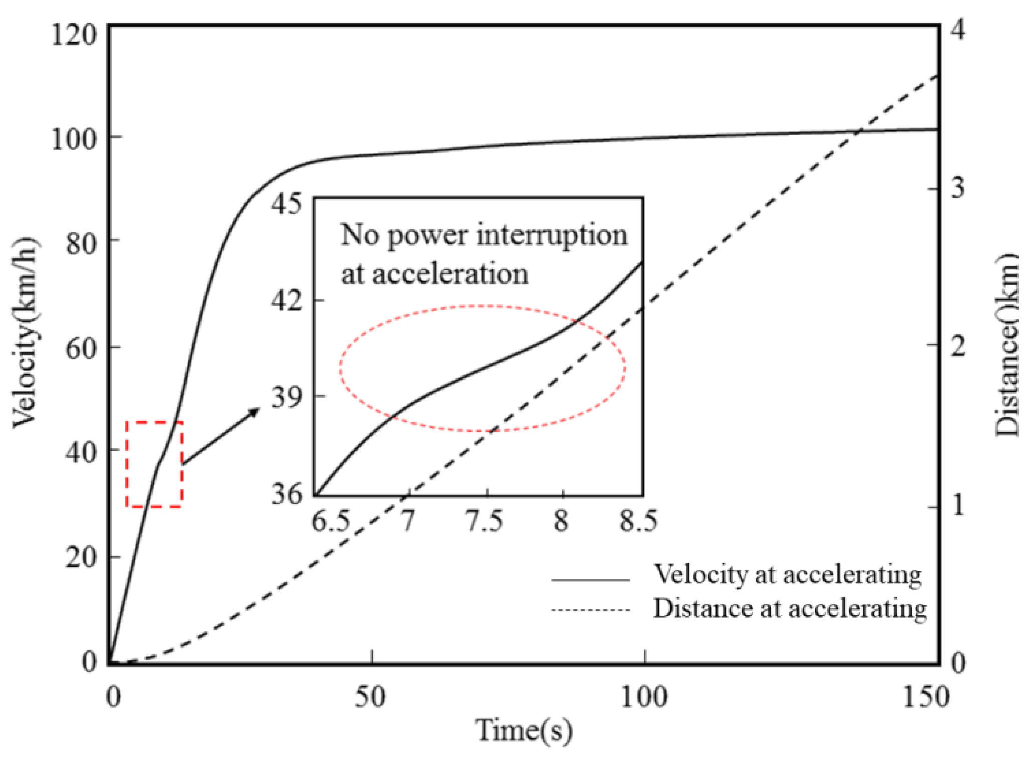
4.2.2. Climbing Performance

Based on the actual road conditions, the acceleration performance and hill climbing performance of the vehicle under full load were simulated and analyzed. For the traditional single-motor drive configuration, the vehicle was prone to power interruption during the acceleration process of 0–50 km/h. In this paper, the dual-motor coupling variable-speed drive configuration was adopted. It can be seen from the speed change curve shown in Figure 16 that the vehicle does not experience power interruption during the acceleration process of 0–50 km/h, delivering excellent driving performance, which fully meets the high-sloped mountain operating environment.

4.2.3. Hydrogen Consumption

The hydrogen consumption of the whole vehicle during the actual road conditions is shown in Figure 17. Compared with the un-optimized EMS, the hydrogen consumption was significantly reduced under the optimized EMS, which benefited from the optimized fuzzy logic control strategy. The traction battery provided most of the demand power of the vehicle when the SOC value was high, until it dropped to the expected SOC value, at which time the requested power was supplied by the FC system. The vehicle’s hydrogen consumption per 100 km was 4.48 kg under the optimized EMS. For the original EMS, despite the high SOC value, the traction battery still executed the charging command. Accordingly, the FC needed to increase the load to ensure the operation of the vehicle demand and the charging of the traction battery. Therefore, the hydrogen consumption per 100 km was 5.65 kg at this time. In summary, the optimized EMS can improve the energy transfer efficiency of the vehicle compared with the original EMS, and increase the economic benefit of hydrogen consumption by 20.7%.

5. Conclusions

In this manuscript, an approach to the powertrain system design of the PEMFC battery HEV was presented, and an optimized EMS for the FC intercity coach on the basis of the fuzzy logic control approach was optimized simultaneously. With the presented method, the optimal dimensions of the core components and the optimal control parameters for the operation of the powertrain were determined. To develop the performance and durability for the FC intercity coach, the suggested EMS allows the FC to operate efficiently to the maximum extent, consequently limiting the power output dynamics of the FC and saving hydrogen consumption.
Furthermore, the optimized EMS could effectively cut down the usage of traction batteries and reduce the variation of the DC bus voltage. Then, it could more actively ensure that the SOC of the traction battery was guaranteed at around 60% during the regular FC intercity coach operation. The results of the above comprehensive optimization represent a balanced method with an extended PEMFC and traction battery lifetime. Furthermore, the FCEV applied in the cold mountainous area had completed the performance test of the low-temperature and complex slope road conditions, and the power performance of the vehicle, the driving performance, and the hydrogen consumption economy were investigated. The results show that the developed vehicle can achieve an excellent driving performance with no power interruption during the acceleration process with the dual-drive coupled power system. At the same time, the hydrogen fuel consumption per 100 km was reduced by 20.7%, from 5.65 kg to 4.48 kg. In conclusion, the practical approach for EMS optimizations proposed in this study might lay the foundation for commercialization and broad application of the highly energy-efficient technology for FC intercity coaches. Furthermore, in addition to meeting the rapid response of power required, the control target of the vehicle’s FC system must also consider the impact of the control strategy on the durability of the FC, which is also the development direction of further breakthroughs in the future. It is expected that the product performance of the fuel cell system will be significantly improved after several rounds of technical iteration.

Author Contributions

Conceptualization, Z.L.; Data curation, Q.H.; Formal analysis, Z.L.; Investigation, J.H.; Methodology, K.L.; Software, H.W.; Validation, E.Z. and C.W.; Writing—original draft, J.H.; Writing—review and editing, Z.L., J.H. and Z.W. All authors have read and agreed to the published version of the manuscript.

Funding

The research was funded by the Ministry of Science and Technology of the People’s Republic of China [2020YFF0305702, 2018YFB0105605] and Beijing Municipal Science & Commission [D171100007517002], China.

Institutional Review Board Statement

Not applicable.

Informed Consent Statement

Informed consent was obtained from all subjects involved in the study.

Data Availability Statement

The datasets analyzed during the current study are available from the corresponding author on reasonable request.

Conflicts of Interest

The authors declare no conflict of interest.

Nomenclature

vVelocity
nSpeed
rWheel rolling radius
PmPeak power
NmMaximum rotational speed
NrRated rotation speed
gGravity acceleration
AWindward vehicle area, m2
ηtTotal mechanical transmission efficiency
PauxPower consumption of the whole vehicle auxiliary electrical equipment
βExpand the constant power region coefficient
PrPower rating
TmPeak torque
TrNominal torque
λMotor overload coefficient
ηDCWorking efficiency of DC/DC
U0Power battery rated voltage
ηmotorEfficiency of motor and inverter
SRange, 100 km
mMaximum total mass of the vehicle
δRotation mass conversion coefficient
ηbatEfficiency of traction battery discharge

References

  1. Fathy, A.; Yousri, D.; Alanazi, T.; Rezk, H. Minimum hydrogen consumption based control strategy of fuel cell/PV/battery/supercapacitor hybrid system using recent approach based parasitism-predation algorithm. Energy 2021, 225, 120316. [Google Scholar] [CrossRef]
  2. Yao, J.; You, F. Simulation-based optimization framework for economic operations of autonomous electric taxicab considering battery aging. Appl. Energy 2020, 279, 115721. [Google Scholar] [CrossRef]
  3. Lee, D.Y.; Elgowainy, A.; Kotz, A.; Vijayagopal, R.; Marcinkoski, J. Life-cycle implications of hydrogen fuel cell electric vehicle technology for medium and heavy-duty trucks. J. Power Sources 2018, 393, 217–229. [Google Scholar] [CrossRef]
  4. Liu, F.; Mauzerall, D.L.; Zhao, F.; Hao, H. Deployment of fuel cell vehicles in China: Greenhouse gas emission reductions from converting the heavy-duty truck fleet from diesel and natural gas to hydrogen. Int. J. Hydrogen Energy 2021, 46, 17982–17997. [Google Scholar] [CrossRef]
  5. Tang, A.; Yang, Y.; Yu, Q. A review of life prediction methods for PEMFCs in electric vehicles. Sustainability 2022, 14, 9842. [Google Scholar] [CrossRef]
  6. Li, Y.; Taghizadeh, H.F. The economic feasibility of green hydrogen and fuel cell electric vehicles for road transport in China. Energy Policy 2022, 160, 112703. [Google Scholar] [CrossRef]
  7. Jafari, K.H.; Brenna, M.; Li, H. Fuel cell hybrid locomotive with modified fuzzy logic based energy management system. Sustainability 2022, 14, 8336. [Google Scholar] [CrossRef]
  8. Baroutaji, A.; Arjunan, A.; Robinson, J. PEMFC poly-generation systems: Developments, merits, and challenges. Sustainability 2021, 13, 11696. [Google Scholar] [CrossRef]
  9. He, X.; Wang, F.; Wallington, T.J. Well-to-wheels emissions, costs, and feedstock potentials for light-duty hydrogen fuel cell vehicles in China in 2017 and 2030. Renew. Sustain. Energy Rev. 2021, 137, 110477. [Google Scholar] [CrossRef]
  10. Asif, U.; Schmidt, K. Fuel cell electric vehicles (FCEV): Policy advances to enhance commercial success. Sustainability 2021, 13, 5149. [Google Scholar] [CrossRef]
  11. Kim, S.; Jeong, H.; Lee, H. Cold-start performance investigation of fuel cell electric vehicles with heat pump-assisted thermal management systems. Energy 2021, 232, 121001. [Google Scholar] [CrossRef]
  12. Henao, N.; Kelouwani, S.; Agbossou, K. Proton exchange membrane fuel cells cold startup global strategy for fuel cell plug-in hybrid electric vehicle. J. Power Sources 2012, 220, 31–41. [Google Scholar] [CrossRef]
  13. Krishnamoorthy, A.; Rodriguez, C.; Durrant, A. Sustainable approaches to microalgal pre-treatment techniques for biodiesel production: A review. Sustainability 2022, 14, 9953. [Google Scholar] [CrossRef]
  14. Xu, X.; Zhao, J.; Zhao, J.; Shi, K.; Dong, P.; Wang, S.; Liu, Y.; Guo, W.; Liu, X. Comparative study on fuel saving potential of series-parallel hybrid transmission and series hybrid transmission. Energy Convers. Manag. 2022, 252, 114970. [Google Scholar] [CrossRef]
  15. Şefkat, G.; Özel, M.A. Experimental and numerical study of energy and thermal management system for a hydrogen fuel cell-battery hybrid electric vehicle. Energy 2022, 238, 121794. [Google Scholar] [CrossRef]
  16. Song, Z.; Pan, Y.; Chen, H. Effects of temperature on the performance of fuel cell hybrid electric vehicles: A review. Appl. Energy 2021, 302, 117572. [Google Scholar] [CrossRef]
  17. Luo, M.; Zhang, J.; Zhang, C. Cold start investigation of fuel cell vehicles with coolant preheating strategy. Appl. Therm. Eng. 2022, 201, 117816. [Google Scholar] [CrossRef]
  18. Wegmann, R.; Döge, V.; Becker, J. Optimized operation of hybrid battery systems for electric vehicles using deterministic and stochastic dynamic programming. J. Energy Storage 2017, 14, 22–38. [Google Scholar] [CrossRef]
  19. Xun, Q.; Murgovski, N.; Liu, Y. Chance-constrained robust co-design optimization for fuel cell hybrid electric trucks. Appl. Energy 2022, 320, 119252. [Google Scholar] [CrossRef]
  20. Malavatu, J.; O’born, R.; Kepplinger, P. Hybrid energy storage systems of energy and power dense batteries: A survey on modelling techniques and control methods. Procedia CIRP 2022, 105, 794–798. [Google Scholar] [CrossRef]
  21. Meng, J.; Ma, N.; Meng, F. Energy management strategy of hybrid energy system for a multi-lobes hybrid air vehicle. Energy 2022, 255, 124539. [Google Scholar] [CrossRef]
  22. Shi, J.; Xu, B.; Shen, Y. Energy management strategy for battery/supercapacitor hybrid electric city bus based on driving pattern recognition. Energy 2022, 243, 122752. [Google Scholar] [CrossRef]
  23. Saiteja, P.; Ashok, B. Critical review on structural architecture, energy control strategies and development process towards optimal energy management in hybrid vehicles. Renew. Sustain. Energy Rev. 2022, 157, 112038. [Google Scholar] [CrossRef]
  24. Sun, H.; Fu, Z.; Tao, F. Data-driven reinforcement-learning-based hierarchical energy management strategy for fuel cell/battery/ultracapacitor hybrid electric vehicles. J. Power Sources 2020, 455, 227964. [Google Scholar] [CrossRef]
  25. Ettihir, K.; Boulon, L.; Agbossou, K. Optimization-based energy management strategy for a fuel cell/battery hybrid power system. Appl. Energy 2016, 163, 142–153. [Google Scholar] [CrossRef]
  26. Fletcher, T.; Thring, R.; Watkinson, M. An Energy Management Strategy to concurrently optimise fuel consumption & PEM fuel cell lifetime in a hybrid vehicle. Int. J. Hydrogen Energy 2016, 41, 21503–21515. [Google Scholar] [CrossRef]
  27. Iqbal, M.; Becherif, M.; Ramadan, H.S. Dual-layer approach for systematic sizing and online energy management of fuel cell hybrid vehicles. Appl. Energy 2021, 300, 117345. [Google Scholar] [CrossRef]
  28. Geng, C.; Jin, X.; Zhang, X. Simulation research on a novel control strategy for fuel cell extended-range vehicles. Int. J. Hydrogen Energy 2019, 44, 408–420. [Google Scholar] [CrossRef]
  29. Guo, J.; He, H.; Li, J.; Liu, Q. Real-time energy management of fuel cell hybrid electric buses: Fuel cell engines friendly intersection speed planning. Energy 2021, 226, 120440. [Google Scholar] [CrossRef]
  30. Hu, X.; Zou, C.; Tang, X. Cost-optimal energy management of hybrid electric vehicles using fuel cell/battery health-aware predictive control. IEEE Trans. Power Electron. 2020, 35, 382–392. [Google Scholar] [CrossRef] [Green Version]
  31. Ravey, A.; Blunier, B.; Miraoui, A. Control strategies for fuel-cell-based hybrid electric vehicles: From offline to online and experimental results. IEEE Trans. Veh. Technol. 2012, 61, 2452–2457. [Google Scholar] [CrossRef]
  32. Lin, C.; Yi, J.; Yu, X. Gearshift control in engagement process of dual-motor coaxial propulsion system for electric bus. IEEE Access 2022, 10, 43351–43366. [Google Scholar] [CrossRef]
  33. Xu, X.; Liang, J.; Hao, Q. A novel electric dual motor transmission for heavy commercial vehicles. Automot. Innov. 2021, 4, 34–43. [Google Scholar] [CrossRef]
Figure 1. The architecture of the power system for an FCEV.
Sustainability 14 11253 g001
Figure 2. Flowchart of FC powertrain system matching.
Sustainability 14 11253 g002
Figure 3. Scheme of vehicle longitudinal dynamic.
Sustainability 14 11253 g003
Figure 4. Scheme of the drive system and efficiency diagram of the motor.
Sustainability 14 11253 g004
Figure 5. Performance of optional FC system and traction battery. (a) Power efficiency curve of the FC. (b) Voltage characteristic curve of a single battery.
Sustainability 14 11253 g005
Figure 6. The basic concept of the optimized EMS based on fuzzy logic control.
Sustainability 14 11253 g006
Figure 7. Schematic diagram of the FC fuzzy logic controller.
Sustainability 14 11253 g007
Figure 8. The actual intercity coach designed in the study.
Sustainability 14 11253 g008
Figure 9. C-WTVC driving conditions.
Sustainability 14 11253 g009
Figure 10. Power demand of the vehicle.
Sustainability 14 11253 g010
Figure 11. SOC change of the traction battery.
Sustainability 14 11253 g011
Figure 12. The power output of the FC.
Sustainability 14 11253 g012
Figure 13. Traction battery output characteristics.
Sustainability 14 11253 g013
Figure 14. Output energy curve. (a) Original strategy. (b) Optimized strategy.
Sustainability 14 11253 g014
Figure 15. Application scenario.
Sustainability 14 11253 g015
Figure 16. The grade ability of the vehicle under full load.
Sustainability 14 11253 g016
Figure 17. Hydrogen consumption.
Sustainability 14 11253 g017
Table 1. Parameters and performance indexes of the FCEV.
ParameterSymbolValue
Maximum gross massm16,400 kg
Tire size 11R22.5
Drag coefficientCd0.52
Rolling friction coefficientf0.008
Maximum speedvmax120 km/h
Acceleration time from 0 to 50 km/ht15 s
Maximum grade abilityα20%
Starting temperatureT−25–40 °C
Driving Range 500 km
Hydrogen consumption per hundred kilometers 7 kg
Table 2. Basic parameters of the drive motor.
ParametersValue
Peak torque of traction motor1084.82 Nm
Peak torque of auxiliary motor856.09 Nm
Peak power of traction motor147.93 KW
Peak power of auxiliary motor116.74 KW
Efficiency84%
Table 3. Fuzzy logic control rules.
Fuzzy Control Rules for Low Motor Speed
PfcSOC State
LowerLowOptimalHighHigher
ΔPMNoptimaloptimalsmallersmallersmaller
Nbigoptimalsmallsmallsmall
ZERObiggerbigoptimaloptimaloptimal
Pbiggerbiggerbigbigoptimal
MPbiggerbiggerbiggerbigbig
Fuzzy control rules for high motor speed
ΔPMNoptimaloptimalsmallersmallersmaller
Nbigoptimalsmallsmallsmall
ZERObiggerbigoptimaloptimaloptimal
Pbiggerbigbigoptimaloptimal
MPbiggerbiggerbiggerbigoptimal
Publisher’s Note: MDPI stays neutral with regard to jurisdictional claims in published maps and institutional affiliations.

