Article

Coupling Mechanism of Coal Body Stress–Seepage around a Water Injection Borehole

1
College of Safety and Environmental Engineering, Shandong University of Science and Technology, 579 Qianwangang Road, Huangdao District, Qingdao 266590, China
2
State Key Laboratory of Mining Disaster Prevention and Control Co-Founded by Shandong Province and the Ministry of Science and Technology, Shandong University of Science and Technology, Qingdao 266590, China
*
Author to whom correspondence should be addressed.
Sustainability 2022, 14(15), 9599; https://doi.org/10.3390/su14159599
Submission received: 14 July 2022 / Revised: 30 July 2022 / Accepted: 2 August 2022 / Published: 4 August 2022

Abstract

:
In China, coal seam water injection technology is widely used in the prevention and control of mine gas and dust disasters. The evolution law of stress–seepage field in the range of hydraulic influence in the process of coal seam water injection is the most basic theoretical problem in coal seam water injection technology. Therefore, this paper first uses the radial seepage experimental system to test the permeability of raw coal samples, and then numerically inverts the stress–seepage evolution law of the coal body around the water injection hole. The results show that the coal seam permeability decreases exponentially with the increase in the experimental overburden pressure. The dynamic water intrusion causes the pressure relief area and the stress concentration area to transfer to the deep part of the coal body, and abnormal stress occurs near the water injection hole wall. The composite stress area formed by the superposition of stress and pore water pressure reduces the permeability of the hole wall. During the radial development of water injection, the pore water pressure dropped sharply and eventually tended to zero, while Darcy’s velocity decreased significantly (within the pressure relief zone, it rapidly decreased from 7.26 × 10⁻³ m s−1 to 2.5 × 10⁻³ m s−1 (by 65.56%)). Near the initiation point, the maximum step-down height of Darcy’s velocity decreased from 6.73 × 10⁻³ m s−1 to 5.27 × 10⁻³ m s−1 (by 22.73%). This can make it clear that the seepage velocity presents a non-Darcy seepage phenomenon under the influence of pore pressure.

1. Introduction

The conditions for the occurrence of coal resources in China are complex and, with the increase in coal mining depth and intensity, the prevention and control of coal and gas outbursts, dust, and mine disasters in general has become more difficult [1,2,3,4,5,6]. At present, the most largely adopted technology in China for reducing the concentration of dust (from the source) is coal seam water injection. This technology is capable of softening the coal body, transforming its mechanical properties, reducing the original in situ stress of the coal seam, and reducing the risk of coal and gas outbursts [7,8,9,10,11,12,13]. In brief, it consists of the construction of drilling holes before coal seam mining and the injection of high-pressure water into the crack pores of the coal body. Notably, the coal body would have already undergone several physical and chemical processes (e.g., fracturing, pore opening, fluid wedging, erosion, wetting) [14]. Therefore, revealing the coal stress–seepage coupling mechanism around the water injection borehole during coal seam water injection is expected to provide new insights in the solid–liquid coupling theory for rock mechanics and is based on a solid integration of elastic, rock, fracture, and fluid mechanics [15,16,17].
Coal bodies can be described as typical porous fractured medium structures. Notably, the development of their internal structure directly determines their seepage characteristics; moreover, their structure dynamically evolves with the mechanical environment [18,19,20,21,22]. For this reason, Yang et al. [23] established a hydraulic–mechanical coupling model based on the numerical manifold method (NMM) to study the propagation of predetermined fractures driven by fluid pressure. Shen et al. [24] established a stress–seepage damage coupling model for the hydraulic fracturing of rock masses and analyzed the crack propagation process based on a plane stress model of rock masses with initial cracks. Miehe et al. [25] proposed a new rate-independent incremental variational framework for diffusion and fracture behavior based on the evolution of the local historical field. To further clarify the dynamic evolution process of crack development, a large number of scholars have described the crack propagation evolution law based on the phase field model [26,27,28,29,30,31,32,33,34]. However, during crack propagation, due to differences between the mechanical environment and the coal structure, the crack surface is usually not smooth. To investigate the relationship between crack deformation and fluid flow, some scholars have also carried out accurate quantitative characterization studies on rough surfaces [1,35,36,37,38]. Overall, the main factor explaining the formation of cracks during coal seam water injection appears to be mechanical damage: the water injection pressure would cause an expansion of the damage range and aggravate the damage [39,40,41,42]. As the fractures continue to expand and extend along the weak surface, the opening of multiple levels of fractures would cause fatigue damage to the fractured rock mass under stress cyclic loading conditions and the tensile strength would continue to decrease, resulting in a decrease in the fracture initiation pressure [26,43,44,45]. During the entire process of coal and rock damage, deformation, and progressive fracture, the distribution of stress–seepage fields in different areas of the coal body around the borehole is regulated by a complex interaction law, which should be considered when studying the mutual coupling relationship between stress damage and seepage. Zhao et al. [46] proposed a dual-medium seepage model, including an equivalent continuum and discrete fractured media, to simulate the seepage–damage coupling effect of fractured rock masses. Cao et al. [47] established the non-linear seepage equation of coal seam water injection by analyzing the stress distribution on the working face and its influence on the coal seam water injection characteristics; moreover, they studied the water injection head, the seepage velocity, the water injection flow rate, and other parameters by considering the characteristics of the solution. To determine the law of temporal and spatial evolution, Jasinge et al. [48] conducted gas permeability test experiments on coal samples under different confining pressures, obtaining a law describing stress–permeability changes in Australian lignite.
To sum up, due to the extremely complex dynamic process of water invasion during coal water injection, the coupling mechanism of coal body stress and pore water pressure around the water injection borehole is also very complicated. This mechanism is strictly connected to the evolution of the coal mechanical structure and the seepage characteristics around the borehole before and after water injection. An in-depth analysis and discussion of the laws describing such a mechanism is expected to clarify the expansion and extension of fractures in water-injected coal bodies, increase the scope of influence of water injection, and provide fundamental information for improving the effect of this technology. Here, we considered a raw coal sample obtained from coal seam No. 10 in Luling Coal Mine. First, the permeability of the coal sample was tested by using a radial seepage experimental system and the permeability of the coal sample before water injection under different overburden pressure conditions was obtained. Second, by considering the mechanical characteristics of the coal sample, the dynamic evolution law of stress–seepage around the borehole during the coal seam water injection process was inverted by using the COMSOL Multiphysics 5.4 numerical simulation software. Finally, based on the numerical simulation and experimental results, the coupling mechanism of stress and pore water pressure in the four stages of the uninjected section, at the initiation of water injection, during crack expansion, and at the end of water injection were discussed. The study can be extended to similar structures of coal seams or other mining areas, providing theoretical guidance for the coal seam water injection process.

2. Radial Seepage Experiment of Large Size Raw Coal

2.1. Experimental System

The permeability of a coal seam is an important parameter directly reflecting the fluid seepage ability in the process of water injection, which determines the wetting effect of water injection. It is difficult to measure the permeability parameters of a coal seam on site due to the existing technology. At present, for the study of coal seam permeability, a large number of scholars mainly conduct laboratory research on small-size briquette-pressed coal samples or small-size raw coal samples [49,50,51,52]. Although laboratory tests are easy to perform and repeatable, there are still large errors in the test results of coal seam permeability due to the influence of coal sample size. To this end, a large-scale raw coal radial seepage experimental system was independently developed. On the basis of similar studies, the size of a coal sample specimen was further expanded, and the original fracture structure of a coal seam was reduced as much as possible. The influence of the coal sample boundary effect on the measurement parameters was reduced, and the accuracy of measurement results was improved. The experimental system is mainly composed of an overburden loading unit, a gas injection control unit, a vacuum unit, and a data acquisition and real-time monitoring unit (consisting of four parts). The structure of the experimental system is shown in Figure 1:

2.2. Experimental Process

2.2.1. Coal Sample Preparation

The experimental coal samples were taken from the tunneling face of coal seam No. 10 of Luling Coal Mine in the Huaibei Mining Area. The coal seam was stable and had a simple structure. The coal body was represented by a black glass shiny block with flat fractures and mainly bright briquette, belonging to the bituminous coal rank. A large number of gas coal samples were collected from the newly exposed coal wall of the excavation face at the site, sealed, and sent to the laboratory to test the industrial analysis values and the mechanical parameters. The test results are shown in Table 1 and Table 2.
According to the experimental research requirements, the largest and most complete lump coal sample collected from the site was selected for further processing. After drilling, cutting, and grinding, this sample was processed into a cylindrical shape with a diameter of 0.3 m and a height of 0.1 m. To reduce the influence of man-made disturbance on the coal sample, and to make the flatness and smoothness of the processed coal sample meet the required experimental standards, the speed of the machine tool was kept low as much as possible during the processing. The processed coal sample was finally wrapped and sealed with plastic wrap and sent to the laboratory. Once there, the coal sample was placed vertically in the center of a faceplate and quick-drying cement was poured in the space between the sidewall of the coal sample and the faceplate. The sample was, hence, left untouched for 7 days to allow the quick-drying cement to harden completely. Once the cement was solidified, a water injection hole was drilled into it from the bottom to complete the preparation of the raw coal specimen. The entire preparation process is shown in Figure 2.

2.2.2. Experimental Program

Using the experimental system described above, the prepared raw coal specimens were used to complete the gas radial percolation experiments on the coal samples before water injection under different overpressure conditions. The specific experimental steps were as follows: clean-up of impurities inside the cylinder; placement of a thin ring-shaped silicone gasket at the contact position of the cylinder bottom with the faceplate; wiping of the faceplate’s outside part and placement of clean coal samples at the center of the cylinder body; alignment of the bottom of the faceplate’s orifice with the exhaust port at the bottom of the cylinder; sequential installation of the pressure plate, sealing piston, and cylinder head; connection of the pressure transmitter to the oil, water, and gas pipelines; check of the device’s air tightness. After the installation was complete, the data acquisition and real-time monitoring unit and the hydraulic pump were turned on and the sealed piston started to apply axial pressure in the sample, simulating the overburden pressure. After the pressure sensor stabilized, the lower cylinder was vacuumed with a vacuum pump until the gauge pointer pointed to the far left. After adjusting the overburden pressure to reach the required pressure value for the experimental program, the argon gas was let in and the gas outlet was opened at the same time. After the instantaneous flow of argon gas at the outlet stabilized, the sensors and flowmeters were used to measure the internal and external boundary pressures and the argon flow. The overburden pressure was then changed and the above experimental steps were repeated: the complete gas radial percolation experiment was reconducted under overburden pressures of 6 MPa, 9 MPa, 12 MPa, and 15 MPa. The entire experimental process is shown in Figure 3.

2.3. Experimental Results

By using the radial seepage experimental system, completing the gas radial seepage experiment test under different overburden pressure conditions, and substituting the experimental data into Equation (1) [53], it was possible to calculate the coal seam permeability under different overburden pressure conditions before water injection. The experimental test results are shown in Table 3.
k = Q 0 μ p 0 ln r e / r w π h p e 2 p w 2
In Equation (1), k is the permeability of the coal seam (mD), μ the fluid viscosity coefficient, p 0 the laboratory atmospheric pressure (101,325 Pa), and Q 0 the gas flow rate measured at the laboratory temperature and under pressure p 0 (mL s−1). Moreover, p w and p e are the inner and outer boundary pressures, respectively (MPa), r w and r e are the inner and outer boundary radiuses, respectively (cm), and h is the thickness of the raw coal sample (cm).
Table 3. Experimental test results.
Experiment NumberBurden Pressure (MPa)Gas Injection Pressure (MPa)Outlet Pressure (MPa)Gas FlowGas Permeability (mD)
(mL min−1)
160.30.131518672.49
290.30.084833.3320.17
3120.30.031833.337.18
4150.30.022080.81
Previous studies have shown that coal permeability and the external overburden load are linked mainly by linear, exponential, quadratic, and power-law relationships [54]. According to the coal seam permeability and gas flow rate distribution in relation to the overburden pressure, the relationship between the coal seam permeability, the gas flow test results, and the overburden pressure was fitted exponentially. After fitting, it is found that the two have a good matching relationship, and the fitting coefficients are greater than 0.99, indicating that the fitting effect is good. The fitting curve is shown in Figure 4. Notably, the changes in coal seam permeability and gas flow rate in relation to the overburden pressure are basically consistent and show an exponential decrease. Under a constant gas injection pressure, the measured coal seam permeability of the coal sample decreased significantly under an increasing overburden pressure; however, the decreasing rate gradually decreased over time. When the overburden pressure increased from 6.0 MPa to 15.0 MPa, the measured permeability of the coal seam decreased from 72.49 mD to 0.81 mD (by 98.88%). In an ideal state, should the overburden pressure increase indefinitely, the coal seam permeability would decrease and gradually tend to zero. The main reason for this is that, as the overburden pressure increases, the coal body becomes compacted and deformed. The greater the overburden pressure, the greater would be the deformation value and the density of the internal porous structure. Notably, a porous structure with narrow spaces would lead to the seepage of gas in the coal body and to a reduction in coal seam permeability. At the same time, the fitting curve of the gas flow rate in relation to the overburden pressure confirms that coal compaction can lead to gas seepage under increasing overburden pressure.

3. Numerical Simulation Analysis of the Stress–Seepage Coupling Law

From the radial seepage experiment, it appears that stress is the direct cause of coal body deformation. However, due to the change in coal seam strike and dip angle, the occurrence of the coal seam is not at a unified height, resulting in different overburden pressures on different positions of the coal seam and different mechanical environments of the coal seam. The permeability of a coal seam changes with the change in overburden load conditions, so the stress–seepage coupling in the process of water injection presents a dynamic evolution law at different positions. However, as a typical grey system, coal seams cannot directly obtain the actual change of stress in the process of water injection, and the radial seepage experimental system cannot completely reproduce the evolution characteristics of stress. Based on the coal seam permeability obtained by the radial seepage experiment and on the mechanical characteristics parameter of the coal sample, we used the COMSOL Multiphysics 5.4 numerical simulation software to invert the stress–seepage field coupling relationship and to further analyze the characteristics of stress distribution and dynamic evolution of Darcy seepage in the surrounding area of the borehole during the water injection process.

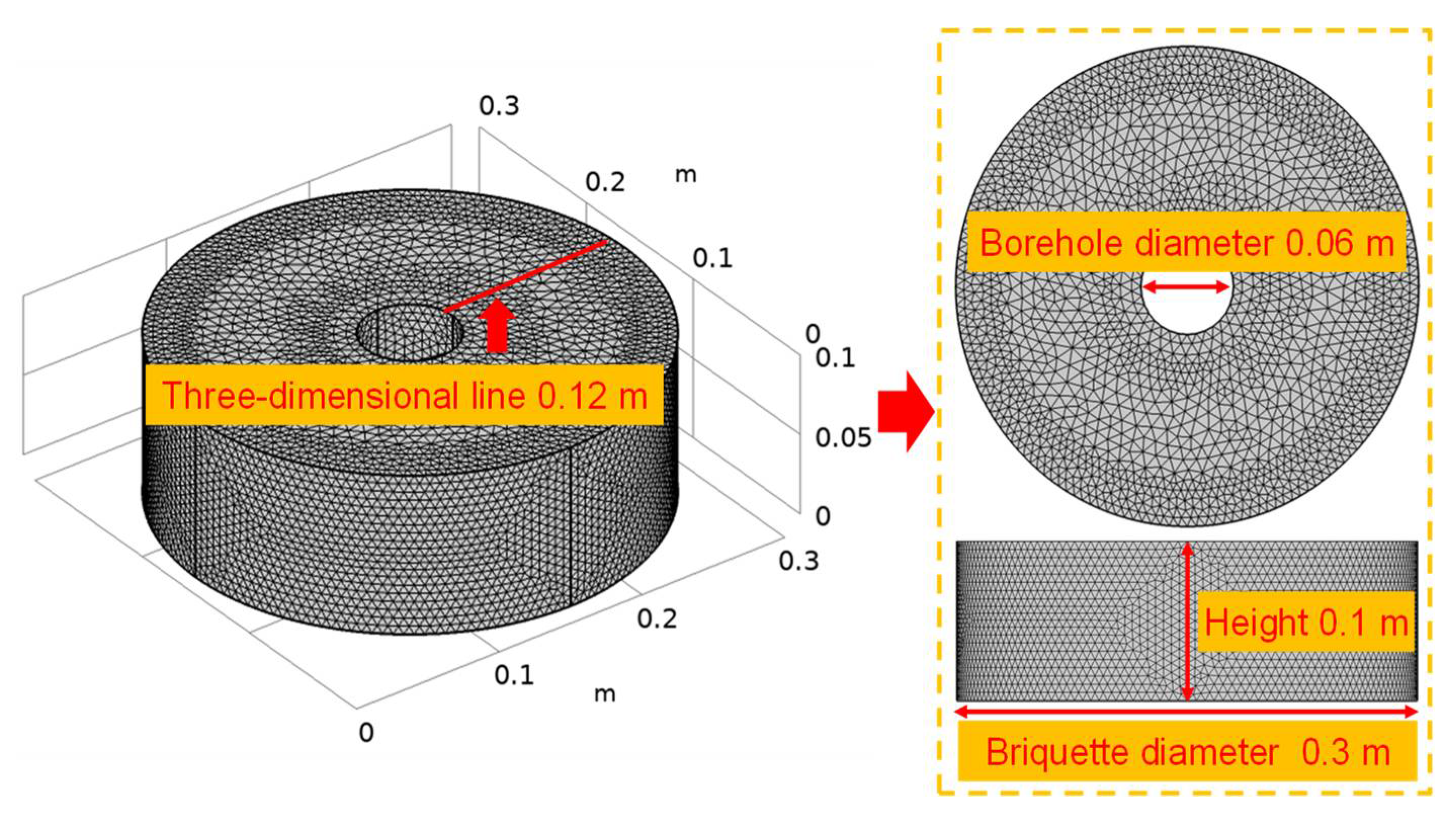
3.1. Physical Model and Parameter Settings

The coal seam water injection process is a multi-field coupling process accompanied by coal matrix deformation and coal internal seepage. The pressure water will affect the mechanical properties of coal around the borehole, the distribution of stress field, and the change of pore pressure in seepage field. Here, the coal seam water injection calculation process was assumed to be effectively described by an isotropic seepage model, and the seepage process was assumed to conform to Darcy’s law. The COMSOL Multiphysics 5.4 simulation software was used to simulate the stress–seepage evolution law during the water injection process and the coupling was mainly completed through the “poroelasticity” multiphysics interface. The “poroelasticity” multiphysics interface combines the transient formula of “Darcy’s law” with the quasi-static formula of “Solid Mechanics”. Notably, the pore pressure in the “Darcy’s law” interface acts as the load of the “Solid Mechanics” interface, causing the coal body to expand or contract. The “Solid Mechanics” interface uses the mechanical equilibrium equation to control the elastic deformation of coal structure, and the “Darcy’s law” interface controls the fluid flow through seepage and continuity equation. Our geometric model was established according to the size of the radial seepage experimental system, using a free tetrahedral mesh. The geometric model obtained after applying the mesh is shown in Figure 5, and the relevant parameters of the model are shown in Table 4.
As shown in Figure 5, the geometric model was established using the Boolean operation and the segmentation method. The basic geometric model was a cylinder with a diameter of 0.3 m and a height of 0.1 m. An empty attribute unit with a diameter of 0.06 m was set inside the model to simulate water injection drilling. In the “Solid Mechanics” interface, the upper part of the model was a free surface. A vertical downward overburden load was applied to the upper surface of the geometric model, and a specified displacement was set on the model’s periphery and bottom. In the “Darcy’s law” interface, water injection pressure was applied around the borehole, and the initial coal sample permeability required by the model corresponded to the coal seam permeability measured during the radial seepage experiment. The model mesh attributes included the following: 136,422 tetrahedrons, 14,446 triangles, 520 edge elements, 16 vertex elements, minimum element quality = 0.2124, average element quality = 0.6782. Notably, the mesh size near the borehole and at the outer boundary of the model was predefined as extremely fine (to improve the accuracy of the model calculation); meanwhile, the grid size in other areas was pre-defined as ultra-fine. During the simulation calculations, the overburden pressure and the water injection pressure changed, multiple sets of water injection simulation experiments were carried out, and the simulation results were compared and analyzed.

3.2. Basic Theory

3.2.1. Mechanical Equilibrium Equation

Poroelasticity generally describes the interaction between fluid flow and solid deformation in elastic porous media. During coal seam water injection, the coal body’s pore water pressure causes the deformation of the coal body’s structure. The elasticity balance equation of the deformation can be obtained from Newton’s second law. The system of equations that describes the quasi-static deformation is hence [55]:
σ = F
where σ denotes the stress tensor and F is the external body forces. The stress tensor is augmented by the pressure load due to changes in pore pressure. The stress in the constitutive relationship that controls the porous elastic deformation of coal and rock is mainly related to strain and the fluid pore water pressure. The stress–strain relationship for linear materials relates to the stress tensor and the strain tensor ε through the elasticity matrix C (which, for isotropic materials, is a function of Young’s modulus E and Poisson’s ratio ν).
σ = C ε α B p f I
Among them, σ represents the stress tensor, ε the strain tensor, p f the fluid pore pressure, and α B the Biot–Willis coefficient.
Following Biot’s theory [56], an increase in fluid content   ξ is related to an increase in volumetric strain and pore pressure, and the fluid pore pressure is directly proportional to the expansion of the porous matrix of coal and the change in fluid content:
p f = M ξ α B ε vol
The variable M represents Biot’s modulus, which is the reciprocal of the storage coefficient S in Darcy’s law. Assuming that the coal structure is an ideal porous material, S can be defined as:
S = ε p K f + α B ε P K s
where ε p represents the porosity of the coal body, K f compressive modulus (the reciprocal of the fluid compressibility χ f ), and K s the bulk modulus of the coal body.

3.2.2. Percolation and Continuity Equations

During coal water injection, water is driven by the newly created pressure gradient to rapidly expand and penetrate in the pores and cracks of the coal body. The correspondent motion equation satisfies the law of conservation of mass and energy; therefore, the seepage of high-pressure water in the coal body must satisfy Darcy’s law. This law implies that the velocity field is mainly determined by the pressure gradient, the fluid viscosity, and the structure of the porous medium. Taking the gravity effect into account, Darcy’s law satisfies the following relationship:
  u = k μ p f + ρ f g D
Without considering the effect of gravity, Darcy’s law can be expressed as:
u = k μ p f
where u is Darcy’s velocity (m s−1), k the permeability of the coal seam (m2), μ the fluid’s dynamic viscosity (Pa s), pf the pore water pressure of coal (Pa), ρf the fluid’s density (kg m−3), g the gravity acceleration (m s−2), and D the elevation (m). Darcy’s law and the continuity equation can be combined in the interface of Darcy’s law physics (8) [57]:
t ρ f ε p + ρ f u = Q m
In the formula, εp is the porosity of the coal seam and Qm the quality source term (kg m−3 s−1). To describe the fluid flow, Darcy’s law (7) can be substituted into the continuity Equation (8), obtaining the generalized governing equation:
t ρ f ε p + . ρ f k μ p f = Q m
By expanding the time derivative term, the following Equation (9) is obtained:
t ρ f ε p = ε p ρ f t + ρ f ε p t
Then, by defining porosity and density as functions of pressure, and by applying the chain rule to expand the right side of Equation (10), we obtain:
ε p ρ f t + ρ f ε p t = ε p ρ f p f   p f t + ρ f ε p p f p f t
The fluid compressibility can be defined as χ f = 1 ρ f ρ f p f . By combining it with Equations (10) and (11), we get:
t ρ f ε p = ρ f ε p χ f + ε p p f p f t = ρ f S p f t
Subsequently, by incorporating Equation (12) into Equation (9), the generalized governing equation can be expressed as follows [58]:
ρ f S p f t + . ρ f k μ p f = Q m
The change rate of the coal matrix’s volumetric strain can be represented as ε vol / t . During the evolution of the water injection time and space, the pore space of the coal body expands. As ε vol / t increases, the volume fraction available for the fluid also increases and leads to the formation of a liquid sink. Considering the negative sign in the source term Q m = ρ f α B ε vol / t , the generalized governing Equation (13) can be transformed into the following:
ρ f S p f t + . ρ f k μ p f = ρ f α B ε vol t
where S is the storage coefficient (Pa−1), which can be interpreted as the weighted compressibility of the coal matrix and fluid. Equation (14) can be solved using the poroelastic storage model in the physics interface of Darcy’s law.

3.3. Evolution of the Stress Field around the Borehole

3.3.1. Characteristics of Coal Stress Distribution around the Borehole before Water Injection

Due to the drilling construction, the original stress state of the coal seam changes and the coal body stress around the drilling site is redistributed. After the hole is formed, the coal body at the hole wall produces a large secondary stress and shear failure. The damaged coal body still bears part of the overburden pressure; however, most of this pressure is transferred to the external coal body unit and generates a concentrated stress, further damaging the coal body. After the stress becomes balanced, a pressure relief zone, a stress concentration zone, and an original stress zone form along the radial direction of the borehole [59]. Here, the stress distribution characteristics of the coal body around the borehole before water injection were simulated by using the solid mechanics interface considering overburden loads of 6 MPa, 9 MPa, 12 MPa, and 15 MPa. The cloud map of coal stress distribution around the borehole before water injection (Figure 6) shows obvious differences in stress around the borehole [60,61].
To further analyze the law of stress changes under different overburden conditions before water injection, a stress distribution cloud map was generated into a stress contour map: a straight line was selected radially along one side of the borehole, and the stress value corresponding to each point on the line was extracted. These values were then used to draw a curve of the radial stress change along the borehole under different overpressure conditions before water injection (Figure 7). Notably, the stress relief and stress concentration zones around the borehole can be easily identified based on the curve change law, while the original stress zone is not reflected by the curve, mainly due to the model size. Meanwhile, Figure 7 shows that, under fixed overburden conditions and with the increase in the radial distance of the borehole, the stress first tends to increase and then to decrease. Moreover, under different overburden conditions and an increasing overburden pressure, the pressure relief zone becomes increasingly smaller, the stress concentration zone increases, and the stress peak moves toward the borehole. Notably, the overburden before the stress peak, the rate of stress growth, the overburden after the stress peak, the rate of stress reduction, the overburden, the stress at the same position, and the peak stress will all increase in parallel.

3.3.2. Characteristics of Coal Stress Distribution around the Borehole during Water Injection

During the water injection process, the seepage of dynamic water in the coal mass disturbed the stress field distribution in the coal and produced a pressure gradient, which was applied to the stress calculation unit as a seepage volume force. Notably, the fracture osmotic pressure acted as a surface force on the open part of the fracture, causing coal and rock mass crack. The initiation and expansion of fissures led to a decrease in the coal and rock stiffness and increased the damage, which, in turn, changed the stress field of the coal and rock. The “Solid Mechanics” and “Darcy’s law” interfaces were coupled to further determine the characteristics of coal stress distribution around the borehole during the water injection process. Under overpressures of 6 MPa, 9 MPa, 12 MPa, and 15 MPa, the water injection pressure was set to be 3 MPa, 5 MPa, 7 MPa, 9 MPa, 11 MPa, and 13 MPa, respectively. However, practice has proved that, when the water injection pressure is greater than the overburden pressure, water running will occur. Therefore, when designing the experimental plan, the water injection pressure was set to be less than the overburden pressure in all the water injection simulation experiments. Figure 8 shows a cloud diagram of stress evolution under different water injection pressures and 15 MPa of overburden pressure. During the water injection process, the overburden pressure and the water injection pressure overlapped, forming a composite stress zone and resulting in a significant change in the coal body stress distribution compared to that before the water injection. Within the water-injection wetting range, the hydraulic influence area was circular and abnormal stress occurred near the water-injection borehole. When the concentrated stress carried by the coal body was higher than the strength of the coal body, the coal body underwent shear failure and could not bear an increase in stress. The peak of the concentrated stress transferred, hence, to the deep coal body and the bearing stress gradually diminished, ultimately becoming lower than that of the original rock: the stress relieved the pressure from the coal body.
To clarify the influence of the overburden pressure and the water injection pressure on the stress distribution of coal, we drew a stress field evolution curve corresponding to the time interval of the water injection process applied to the coal seam (Figure 9). Notably, as the radial distance of the borehole increased, the stress presented a decreasing–increasing–decreasing trend. The main reason is that there is high water pressure around the water injection borehole, resulting in the superposition of axial pressure and water pressure to form a high stress area, while the coal body in the distance has the phenomenon of stress concentration due to the stress around the borehole. The stress dropped to a minimum (wave trough) at a distance of ~0.01–0.02 m from the borehole in the radial direction and reached a maximum (wave crest) at a distance of ~0.1 m from the borehole in the radial direction. Different from what was described by the law of stress change before water injection, a high stress anomaly occurred around the borehole, and the peak stress shifted to a deeper part of the coal body. Under the same overburden conditions, the stress before the trough increased with the water injection pressure, while the opposite trend was observed after the trough. At a longer radial distance from the borehole, the stress change trend was increasingly less affected by the water injection pressure. In fact, when the water injection pressure increased, the stress around the borehole and the trough stress also increased, and the pressure relief area became larger and more efficient. Moreover, with the increase in the water injection pressure, the trough stress and the area of stress concentration transferred to a deeper part of the coal seam. Under an increasing overburden pressure and a fixed water injection pressure, the compaction degree of the coal body around the borehole increased; meanwhile, under an increasing overburden pressure, the stress increased.

3.4. Evolution of the Seepage Field around the Borehole

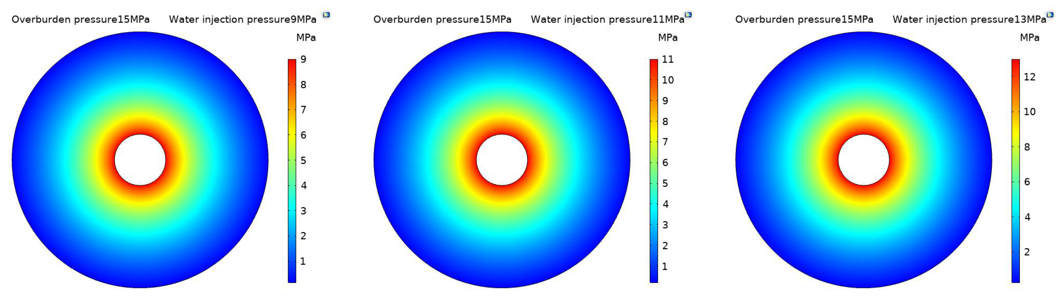
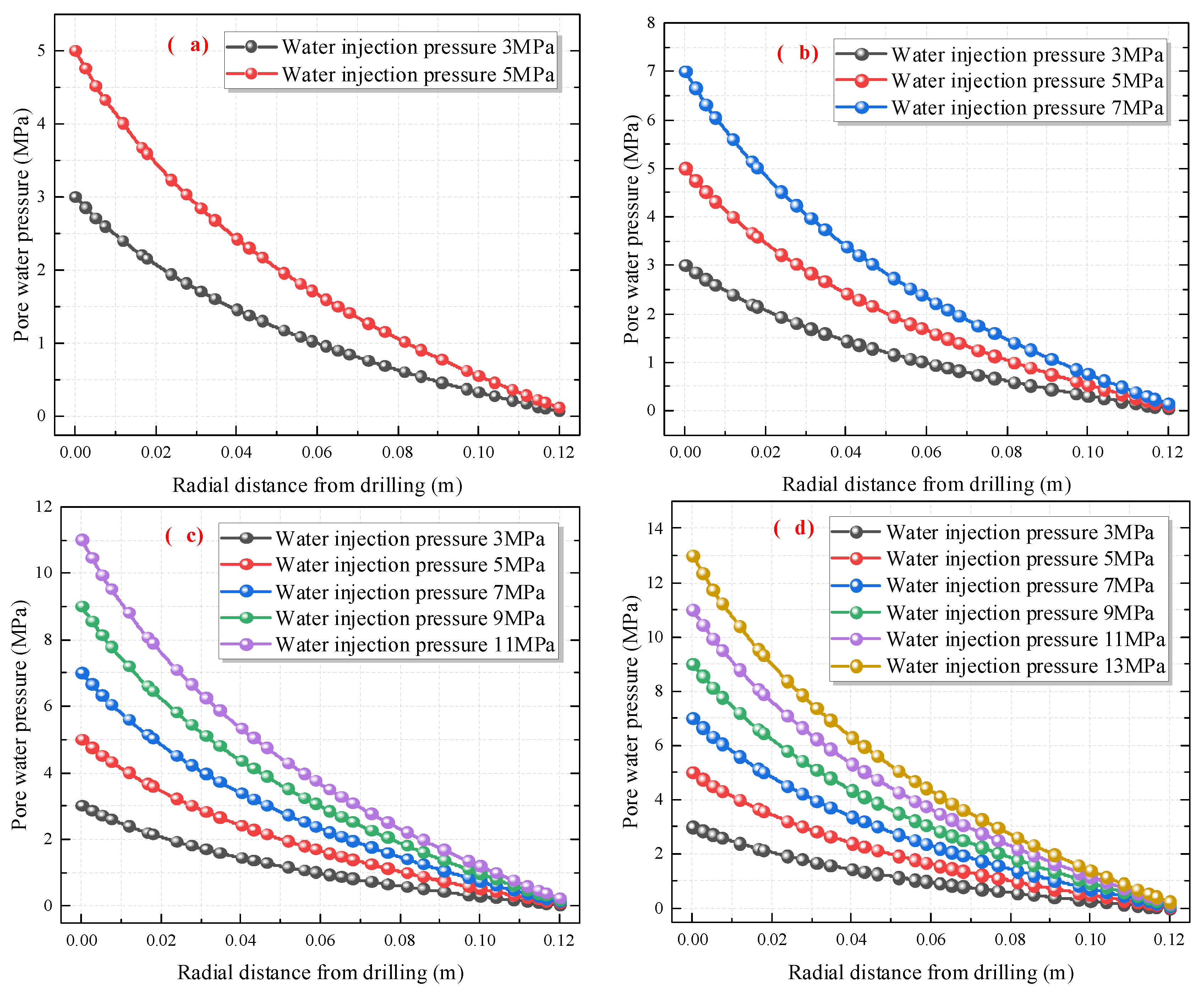
3.4.1. Distribution Characteristics of Pore Water Pressure around the Borehole

Figure 10 shows a cloud diagram of pore water pressure distribution under different water injection pressures and an overburden pressure of 15 MPa. While the water injection pressure varied from 3 MPa to 13 MPa, the pore water pressure in the coal body was distributed in a circular shape and decreased continuously around the water injection hole.
Based on the pressure field evolution curve, we further discussed the pore water pressure distribution characteristics around the borehole during water injection in the coal seam. Figure 11 shows how different water injection pressures can lead to different maximum water pressures around the wall of the water injection borehole. The water pressure near the hole wall was the highest and similar to the water injection pressure. As the radial distance from the borehole increased, the pore water pressure decreased. Notably, the size of the deceleration rate increased with the water injection pressure. Over a certain distance, the pore water pressure was no longer significantly affected by the water injection pressure and gradually approached zero.

3.4.2. Distribution Characteristics of Seepage Velocity around the Borehole

The distribution characteristics of seepage velocity around the borehole were discussed to better define the seepage law of pressurized water in the coal body. Figure 12 shows the distribution curve of Darcy’s velocity obtained by the numerical simulation software along the radial direction of the borehole during coal seam water injection and under overburden loads of 6 MPa, 9 MPa, 12 MPa, and 15 MPa (corresponding to changes in water injection pressure). The curves in Figure 12 demonstrate that, under a constant overburden pressure, Darcy’s velocity increases with the water injection pressure; moreover, near the crack initiation point, Darcy’s velocity drops suddenly and the rate of decrease increases with the water injection pressure. The pore seepage velocity around the borehole was the largest and gradually decreased from the vicinity of the borehole to its surroundings in a stepwise manner. Figure 12a shows that, under an overburden pressure of 6 Mpa and a water injection pressure of 5 MPa, Darcy’s velocity rapidly decreased from 7.26 × 10⁻³ m s−1 to 2.5 × 10⁻³ m s−1 (by 65.56%) after the radial development of water injection within the pressure relief area. Meanwhile, due to the continuous initiation and expansion of cracks, Darcy’s velocity decreased stepwise near the crack initiation point (from 6.73 × 10⁻³ m s−1 to 5.27 × 10⁻³ m s−1), with a sudden decrease of 22.73%. Under a constant water injection pressure, Darcy’s velocity decreased with the increase in the overburden pressure. Notably, Darcy’s velocity dropped suddenly near the crack initiation point: with the increase in the overburden pressure, the fissure and pore structure of the coal body were pressed and closed, hindering crack initiation.
The results of the above analyses indicate that, during coal seam water injection, the coal body underwent seepage, changing from unsaturated to water-saturated. Fractures were well developed in the pressure relief area, and water flowed along the primary fractures of the coal body under the action of the water injection pressure. After passing through the pressure relief zone, the pressurized water entered the stress concentration area, the coal sample gradually became denser, and the water permeability resistance increased. When the water pressure reached the starting pressure, the stress accumulation of the water injection hole wall reached its peak, resulting in mechanical damage: the coal body cracked near the borehole and a cracked seepage channel was formed. Due to the action of high-pressure water, the fluid was in a transient turbulent flow process and Darcy’s velocity suddenly dropped, leading to an unsteady seepage phenomenon. As the radial distance of the borehole increased, Darcy’s velocity decreased stepwise, but the decreasing rate gradually diminished and eventually stabilized. In fact, the coal body was affected by the water injection pressure during the increase in the radial distance: water became unable to penetrate the coal body as its pressure decreased; therefore, the stress concentration area in the coal body gradually changed back to the original stress area.

4. Discussion

Through the analysis of the radial seepage experiment and numerical simulation results, it is found that stress is the direct cause of coal deformation. The permeability and overburden pressure of the coal seam show an exponential decreasing trend, and the real action processes of different mechanical environments on each stage and region of water injection are not the same. Therefore, based on the experimental and numerical simulation results, the dynamic evolution of stress–seepage in the whole process of coal seam water injection can be summarized into four stages: no water injection section, water injection crack initiation, crack propagation, and water injection end. The whole process of water injection and the stress–seepage dynamic evolution is shown in Figure 13.
The radial surrounding rock stress distribution of the borehole during the non-water injection stage is shown in Figure 13a. The stress varied in different zones, and the surrounding rock stress showed an increasing–decreasing–steady change trend [61]. When the coal around the borehole is unloaded unilaterally in the radial direction, the plastic failure occurs in the coal fracture, and the elastic potential energy is released to form the unloading zone. With the radial development of coal fracture, ground stress transfers to the deep part of adjacent coal, resulting in the stress concentration of coal in the adjacent area. The area outside the stress concentration area not affected by borehole mining is the original stress area.
The radial surrounding rock stress and the pore water pressure distribution in the borehole during water injection and the cracking stage are shown in Figure 13b. The surrounding rock stress showed a decreasing–increasing–decreasing–steady change trend, while the pore water pressure decreased exponentially and the dynamic water pressure had a small influence range. The main reason for this is that, in the initial stage of water injection, high-pressure water quickly filled the water injection boreholes in the coal seam. Because the cracks in the pressure relief zone were the most developed, water easily filled the coal cracks and pores, resulting in a particularly high water content. With the increase in the water injection pressure, high-pressure water began to exert compressive stress on the hole wall and on the bedding surface, cutting fissures, and primary fissures in the hole wall and coal seam. The skeleton of the coal body was squeezed, the stress at the orifice increased, and stress accumulation occurred. When the stress accumulated on the hole wall and on the weak surface was greater than the coal seam in situ stress and the coal tensile strength, the primary cracks in the coal around the borehole began to crack further and open, forming an initial main crack. As water continued to penetrate in the coal seam, the volume of the fissures increased. During this process, the coal and rock in the pressure relief zone underwent irreversible deformation and expansion, the radius of the plastic zone extended, and the positions of the pressure relief and stress concentration zones migrated outward from the drilling center.
The radial surrounding rock stress and the pore water pressure distribution in the borehole during the crack expansion stage are shown in Figure 13c. The surrounding rock stress and the pore water pressure distribution were different from those in the initial cracking stage. As the water injection pressure increased, water gradually spread in the stress concentration area of the coal body, the softening degree of the coal body increased, the plastic zone range of the working face increased, and the coal body around the borehole expanded radially. When the stress value of the coal body exceeded the yield stress of the coal body failure, the coal body ruptured under the action of the water wedge: additional cracks opened and gradually expanded. Hence, the pressure relief zone around the borehole became increasingly larger. The degree of stress concentration increased and the stress concentration area shifted to the deeper part of the coal body [62]. At this time, the coal seam stress was represented by a composite stress zone. This was formed by the superimposition of the disturbance stress field caused by liquid injection into the coal seam and the original in situ stress field of the coal seam.
The radial surrounding rock stress distribution in the borehole at the end of the water injection process is shown in Figure 13d. At this time, the coal body had softened due to water intrusion, its supporting capacity was reduced, and its mechanical properties had changed. Under a stress of the surrounding rock equal to that experienced before water injection, wet coal damage occurred, and the range of rupture increased; additionally, the ability of coal to save elastic energy diminished, while its ability to consume elastic energy during plastic deformation increased. Therefore, the recoverable elastic energy stored in the plastic area of the coal seam decreased, the plastic area increased, and the unloading area widened; moreover, the stress concentration peak was reduced and its variation slowed down. Finally, the pressure relief, stress concentration, and original pressure areas were allocated deeper in the coal body compared to the time before water injection [63].

5. Conclusions

In this paper, the permeability of coal samples was determined using a radial seepage experimental system, obtaining the permeability of the original coal seam. By combining this information with the mechanical characteristics of the coal samples, the COMSOL Multiphysics 5.4 simulation software was able to invert the stress–seepage dynamic evolution law of the original coal body around a water injection borehole in different stress environments. Then, based on numerical simulations and experimental results, the dynamic evolution distribution characteristics of the stress and seepage flow during the whole coal seam water injection process were further discussed. The following specific conclusions were drawn:
(1)
The experimental results obtained by using the radial seepage experimental system under different overpressures and before water injection showed that the tested coal seam permeability and flow rate were basically consistent and decreased exponentially with the overpressure.
(2)
Before water injection, the radial stress showed an increasing–decreasing–stable trend. With the increase in the overburden, the scope of the pressure relief area gradually decreased, that of the stress concentration area increased, and the stress peak moved toward the borehole wall. Overall, the greater the overburden, the greater was the stress at the same position and the stress peak.
(3)
During water injection, the stress showed a decreasing–increasing–decreasing–stable trend. Under the influence of water injection, abnormal stress occurred near the water injection hole wall, and a composite stress zone was created from the superposition of stress and of the pore water pressure. This composite stress zone caused a decrease in the hole wall permeability.
(4)
With the radial development of water injection, the pore water pressure dropped sharply and Darcy’s velocity decreased significantly. In particular, within the pressure relief area, Darcy’s velocity decreased rapidly from 7.26 × 10⁻³ m s−1 to 2.5 × 10⁻³ m s−1 (by 65.56%). Near the crack initiation point, Darcy’s velocity dropped from 6.73 × 10⁻³ m s−1 to 5.27 × 10⁻³ m s−1 (by 22.73%).

Author Contributions

Conceptualization, Z.L.; Data curation, P.H. and W.Y.; Funding acquisition, Z.L.; Investigation, Q.G.; Methodology, P.H. and H.Y.; Supervision, Z.L.; Writing—original draft, H.Y.; Writing—review & editing, P.H. All authors have read and agreed to the published version of the manuscript.

Funding

The National Natural Science Foundation of China (52074173, 51934004), Taishan Scholars Project Special Funding (TS20190935), and Development Plan of Excellent Youth Innovation Team in Colleges and Universities of Shandong Province (2019KJH006).

Institutional Review Board Statement

Not applicable.

Informed Consent Statement

Not applicable.

Data Availability Statement

Not applicable.

Acknowledgments

The authors would like to acknowledge the support of the National Natural Science Foundation of China (52074173, 51934004), Taishan Scholars Project Special Funding (TS20190935), and Development Plan of Excellent Youth Innovation Team in Colleges and Universities of Shandong Province (2019KJH006).

Conflicts of Interest

The authors declare no conflict of interest.

References

  1. Kong, B.; Wang, E.Y.; Lu, W.; Li, Z.H. Application of electromagnetic radiation detection in high temperature anomalous areas experiencing coalfield fires. Energy 2019, 189, 13. [Google Scholar] [CrossRef]
  2. Mark, C.; Gauna, M. Evaluating the risk of coal bursts in underground coal mines. Int. J. Min. Sci. Technol. 2016, 26, 47–52. [Google Scholar] [CrossRef]
  3. Wang, G.; Wang, R.; Wu, M.M.; Fan, C.; Song, X. Strength criterion effect of the translator and destabilization model of gas-bearing coal seam. Int. J. Min. Sci. Technol. 2019, 29, 327–333. [Google Scholar] [CrossRef]
  4. Zhao, L.; Ni, G.H.; Sun, L.L.; Qian, S.; Shang, L.; Kai, D.; Xie, J.N.; Gang, W. Effect of ionic liquid treatment on pore structure and fractal characteristics of low rank coal. Fuel 2020, 262, 10. [Google Scholar] [CrossRef]
  5. Zhao, T.B.; Guo, W.Y.; Tan, Y.L.; Yin, Y.C.; Cai, L.S.; Pan, J.F. Case Studies of Rock Bursts Under Complicated Geological Conditions During Multi-seam Mining at a Depth of 800 m. Rock Mech. Rock Eng. 2018, 51, 1539–1564. [Google Scholar] [CrossRef]
  6. Zhou, Q.L.; Herrera, J.; Hidalgo, A. Development of a quantitative assessment approach for the coal and gas outbursts in coal mines using rock engineering systems. Int. J. Min. Reclam. Environ. 2019, 33, 21–41. [Google Scholar] [CrossRef] [Green Version]
  7. Aguado, M.B.D.; Nicieza, C.G. Control and prevention of gas outbursts in coal mines, Riosa–Olloniego coalfield, Spain. Int. J. Coal Geol. 2007, 69, 253–266. [Google Scholar] [CrossRef]
  8. Cheng, W.M.; Nie, W.; Zhou, G.; Yu, Y.B.; Ma, Y.Y.; Xue, J. Research and practice on fluctuation water injection technology at low permeability coal seam. Saf. Sci. 2012, 50, 851–856. [Google Scholar] [CrossRef]
  9. Liu, Z.; Raorao, L.I.; Yang, H.E.; Tian, F.; Zhu, D. A New Fractal Model of Coal Permeability Based on the Increasing Fractal Construction Method of the Menger Sponge. Fractals 2021, 29, 2150187. [Google Scholar] [CrossRef]
  10. Moreno, T.; Trechera, P.; Querol, X.; Lah, R.; Johnson, D.; Wrana, A.; Williamson, B. Trace element fractionation between PM10 and PM2.5 in coal mine dust: Implications for occupational respiratory health. Int. J. Coal Geol. 2019, 203, 52–59. [Google Scholar] [CrossRef]
  11. Sun, B.; Cheng, W.; Wang, J.; Hao, W. Effects of turbulent airflow from coal cutting on pollution characteristics of coal dust in fully-mechanized mining face: A case study. J. Clean. Prod. 2018, 201, 308–324. [Google Scholar] [CrossRef]
  12. Ye, Q.; Wang, G.; Jia, Z.; Zheng, C. Experimental study on the influence of wall heat effect on gas explosion and its propagation. Appl. Therm. Eng. 2017, 118, 392–397. [Google Scholar] [CrossRef] [Green Version]
  13. Zhang, Q.; Zhou, G.; Qian, X.M.; Yuan, M.Q.; Sun, Y.L.; Wang, D. Diffuse pollution characteristics of respirable dust in fully-mechanized mining face under various velocities based on CFD investigation. J. Clean. Prod. 2018, 184, 239–250. [Google Scholar] [CrossRef]
  14. Liu, Z.; Zhao, D.W.; Yang, H.; Li, G.M.; Wang, W.Y. Experimental study on the spontaneous imbibition characteristics of accumulated coal grains. Fuel 2021, 288, 12. [Google Scholar] [CrossRef]
  15. Liu, Z.; Zeng-Hua, L.I.; Yang, Y.L.; Tang, Y.B. Study of Outburst Prevention Technology by Comprehensive Hydraulic Drilling Downward Through Coal-Seam. J. Min. Saf. Eng. 2012, 29, 564. [Google Scholar]
  16. Roy, D.G.; Singh, T.N.; Kodikara, J.; Das, R. Effect of Water Saturation on the Fracture and Mechanical Properties of Sedimentary Rocks. Rock Mech. Rock Eng. 2017, 50, 2585–2600. [Google Scholar] [CrossRef]
  17. Roy, D.G.; Singh, T.N.; Kodikara, J.; Talukdar, M. Correlating the Mechanical and Physical Properties with Mode-I Fracture Toughness of Rocks. Rock Mech. Rock Eng. 2017, 50, 1941–1946. [Google Scholar] [CrossRef]
  18. Schwarz, J.O.; Enzmann, F. Simulation of Fluid Flow on Fractures and Implications for Reactive Transport Simulations. Transp. Porous Media 2013, 96, 501–525. [Google Scholar] [CrossRef]
  19. Xiao, Z.; Meng, L. Numerical Analysis of Effect of Coal Seam Water Injection on Crack Propagation and Water Distribution. Saf. Coal Mines 2016, 47, 159–162+166. [Google Scholar]
  20. Wu, F.; Qi, Q.; Dong, Z.; Li, X.; Jing, S.; Wang, H. Numerical simulation on radial displacement around coal seam water injection drilling. J. Liaoning Tech. Univ. (Nat. Sci.) 2017, 36, 7. [Google Scholar]
  21. Raza, S.S.; Ge, L.; Rufford, T.E.; Chen, Z.; Rudolph, V. Anisotropic coal permeability estimation by determining cleat compressibility using mercury intrusion porosimetry and stress–strain measurements. Int. J. Coal Geol. 2019, 205, 75–86. [Google Scholar] [CrossRef]
  22. Yang, H.; Cheng, W.M.; Liu, Z.; Wang, W.D.; Zhao, D.W.; Yang, W.Z. Study on the Dynamic Evolution Law of the Effective Stress in the Coal Seam Water infusion Process Based on Fractal Theory. Fractals 2020, 28, 13. [Google Scholar] [CrossRef]
  23. Yang, Y.T.; Tang, X.H.; Zheng, H.; Liu, Q.S.; Liu, Z.J. Hydraulic fracturing modeling using the enriched numerical manifold method. Appl. Math. Model. 2018, 53, 462–486. [Google Scholar] [CrossRef]
  24. Shen, Z.Z.; Zhang, X.; Sun, Y.L. Research on stress-seepage-damage coupling model of hydraulic fracturing for rock mass. Jisuan Lixue Xuebao/Chin. J. Comput. Mech. 2009, 26, 523–528. [Google Scholar]
  25. Miehe, C.; Hofacker, M.; Welschinger, F. A phase field model for rate-independent crack propagation: Robust algorithmic implementation based on operator splits. Comput. Meth. Appl. Mech. Eng. 2010, 199, 2765–2778. [Google Scholar] [CrossRef]
  26. Xu, Y.; Zhai, C.; Hao, L.; Sun, X.; Liu, Y.; Li, X.; Li, Q. The Pressure Relief and Permeability Increase Mechanism of Crossing-Layers Directional Hydraulic Fracturing and Its Application. Procedia Eng. 2011, 26, 1184–1193. [Google Scholar] [CrossRef] [Green Version]
  27. Lee, S.; Wheeler, M.F.; Wick, T. Pressure and fluid-driven fracture propagation in porous media using an adaptive finite element phase field model. Comput. Meth. Appl. Mech. Eng. 2016, 305, 111–132. [Google Scholar] [CrossRef] [Green Version]
  28. Zhou, S.W.; Zhuang, X.Y.; Rabczuk, T. Phase-field modeling of fluid-driven dynamic cracking in porous media. Comput. Meth. Appl. Mech. Eng. 2019, 350, 169–198. [Google Scholar] [CrossRef]
  29. Mikelic, A.; Wheeler, M.F.; Wick, T. Phase-field modeling of a fluid-driven fracture in a poroelastic medium. Comput. Geosci. 2015, 19, 1171–1195. [Google Scholar] [CrossRef] [Green Version]
  30. Borden, M.J.; Verhoosel, C.V.; Scott, M.A.; Hughes, T.J.R.; Landis, C.M. A phase-field description of dynamic brittle fracture. Comput. Meth. Appl. Mech. Eng. 2012, 217, 77–95. [Google Scholar] [CrossRef]
  31. Zhou, S.W.; Rabczuk, T.; Zhuang, X.Y. Phase field modeling of quasi-static and dynamic crack propagation: COMSOL implementation and case studies. Adv. Eng. Softw. 2018, 122, 31–49. [Google Scholar] [CrossRef] [Green Version]
  32. Vahab, M.; Khalili, N. Numerical investigation of the flow regimes through hydraulic fractures using the X-FEM technique. Eng. Fract. Mech. 2017, 169, 146–162. [Google Scholar] [CrossRef]
  33. Vahab, M.; Hirmand, M.R.; Jafari, A.; Khalili, N. Numerical analysis of multiple hydro-fracture growth in layered media based on a non-differentiable energy minimization approach. Eng. Fract. Mech. 2021, 241, 14. [Google Scholar] [CrossRef]
  34. Khoei, A.R.; Vahab, M.; Hirmand, M. An enriched-FEM technique for numerical simulation of interacting discontinuities in naturally fractured porous media. Comput. Meth. Appl. Mech. Eng. 2018, 331, 197–231. [Google Scholar] [CrossRef]
  35. Movassagh, A.; Haghighi, M.; Zhang, X.; Kasperczyk, D.; Sayyafzadeh, M. A fractal approach for surface roughness analysis of laboratory hydraulic fracture. J. Nat. Gas Sci. Eng. 2021, 85, 16. [Google Scholar] [CrossRef]
  36. Hirmand, M.R.; Vahab, M.; Papoulia, K.D.; Khalili, N. Robust simulation of dynamic fluid-driven fracture in naturally fractured impermeable media. Comput. Meth. Appl. Mech. Eng. 2019, 357, 23. [Google Scholar] [CrossRef]
  37. Mao, X.U.; Zhou, G.; Qiu, H. Study of Numerical Simulation of Coal Seam Low-pressure Water Injection Based on Three-dimensional Precast Pre-existing Fractures. J. Shandong Univ. Sci. Technol. (Nat. Sci.) 2017, 2, 73–80. [Google Scholar]
  38. Vahab, M.; Khoei, A.R.; Khalili, N. An X-FEM technique in modeling hydro-fracture interaction with naturally-cemented faults. Eng. Fract. Mech. 2019, 212, 269–290. [Google Scholar] [CrossRef]
  39. Zhu, W.; Wei, C.; Tian, J.; Yang, T.; Tang, C. Coupled thermal-hydraulic-mechanical model during rock damage and its preliminary application. Yantu Lixue/Rock Soil Mech. 2009, 30, 3851–3857. [Google Scholar]
  40. Min, T.U.; Miao, X.X.; Colliery, Z.; Mining, H. Deformation Rule of Protected Coal Seam Exploited by Using the Long-Distance-Lower Protective Seam Method. J. Min. Saf. Eng. 2006, 3, 253–257. [Google Scholar]
  41. Duan, M.; Jiang, C.; Guo, X.; Yang, K.; Zhang, X.; Ma, H. Experimental study on mechanical and damage characteristics of coal under cyclic true triaxial loading. Chin. J. Rock Mech. Eng. 2021, 40, 1110–1118. [Google Scholar] [CrossRef]
  42. Beamish, B.B.; Crosdale, P.J. Instantaneous outbursts in underground coal mines: An overview and association with coal type. Int. J. Coal Geol. 1998, 35, 27–55. [Google Scholar] [CrossRef]
  43. Davies, R.; Foulger, G.; Bindley, A.; Styles, P. Induced seismicity and hydraulic fracturing for the recovery of hydrocarbons. Mar. Pet. Geol. 2013, 45, 171–185. [Google Scholar] [CrossRef] [Green Version]
  44. Gai, D.; Zhu, W.; Wei, C.; Niu, L. Pulse fracturing model based on damage mechanics and its numerical simulation. J. Min. Saf. Eng. 2016, 33, 945–950. [Google Scholar]
  45. Lu, P.Q.; Li, G.S.; Huang, Z.W.; Tian, S.C.; Shen, Z.H. Simulation and analysis of coal seam conditions on the stress disturbance effects of pulsating hydro-fracturing. J. Nat. Gas Sci. Eng. 2014, 21, 649–658. [Google Scholar] [CrossRef]
  46. Zhao, Y.L.; Liu, Q.; Zhang, C.S.; Liao, J.; Lin, H.; Wang, Y.X. Coupled seepage-damage effect in fractured rock masses: Model development and a case study. Int. J. Rock Mech. Min. Sci. 2021, 144, 22. [Google Scholar] [CrossRef]
  47. Cao, J.L.; Dong, L.H.; Ai, D.-H.; Wang, F.Y.; Cui, Y.G. Nonlinear seepage law of deep hole water-injection in working face under the influence of mining. Meitan Xuebao/J. China Coal Soc. 2017, 42, 225–232. [Google Scholar]
  48. Jasinge, D.; Ranjith, P.G.; Choi, S.K. Effects of effective stress changes on permeability of latrobe valley brown coal. Fuel 2011, 90, 1292–1300. [Google Scholar] [CrossRef]
  49. Gao, K.; Liu, Z.G.; Liu, J. Study on Permeability Comparison Tests with Two Different Gas Content Coal Samples. Coal Sci. Technol. 2011, 39, 57–59. [Google Scholar]
  50. Wang, D.; Zhang, P.; Wei, J.; Yu, C. The seepage properties and permeability enhancement mechanism in coal under temperature shocks during unloading confining pressures. J. Nat. Gas Sci. Eng. 2020, 77, 103242. [Google Scholar] [CrossRef]
  51. Lu, Y.Y.; Yang, F.; Ge, Z.L.; Zhou, Z.; Lin, X.D. Comparative experiment on influence of clear fracturing fluid and water on coal seam permeability. J. China Coal Soc. 2015, 5, 93–97. [Google Scholar]
  52. Zhang, C.; Zhang, L.; Wang, W. The axial and radial permeability testing of coal under cyclic loading and unloading. Arab. J. Geosci. 2019, 12, 371. [Google Scholar] [CrossRef]
  53. Zhou, S.N.; Lin, B.Q. The Theory of Gas Flow and Storage in Coal Seams; Coal Industry Publishing House: Beijing, China, 1997; pp. 69–90. [Google Scholar]
  54. Huang, Y.; Wang, E. Experimental Study on Coefficient of Sensitiveness Between Percolation Rate and Effective Pressure for Low Permeability Rock. Chin. J. Rock Mech. Eng. 2007, 26, 410–414. [Google Scholar]
  55. Suarez-Rivera, R.; Begnaud, B.J.; Martin, W.J. Numerical Analysis of Open-hole Multilateral Completions Minimizes the Risk of Costly Junction Failures. In Proceedings of the Rio Oil & Gas Expo and Conference, Rio de Janeiro, Brazil, 4–7 October 2004. [Google Scholar]
  56. Biot, M.A. Mechanics of Deformation and Acoustic Propagation in Porous Media. J. Appl. Phys. 2004, 33, 1482–1498. [Google Scholar] [CrossRef]
  57. Zhang, H.; Liu, J.; Elsworth, D. How sorption-induced matrix deformation affects gas flow in coal seams: A new FE model. Int. J. Rock Mech. Min. Sci. 2008, 45, 1226–1236. [Google Scholar] [CrossRef]
  58. Zhou, H.; Liu, J.; Xue, D.; Yi, H.; Xue, J. Numerical simulation of gas flow process in mining-induced crack network - ScienceDirect. Int. J. Min. Sci. Technol. 2012, 22, 793–799. [Google Scholar] [CrossRef]
  59. Liu, Z.; Li, Z.; Yang, Y.; Ji, H. Experimental study of effect of water on sorption and radial gas seepage of coal. Yanshilixue Yu Gongcheng Xuebao/Chin. J. Rock Mech. Eng. 2014, 33, 586–593. [Google Scholar]
  60. Zhen, L.; Wendi, W.; Dandan, C. Numerical Calculation and Analysis of Hole Sealing Parameters of Gas Drainage in Bedding. Min. Res. Dev. 2020, 40, 6. [Google Scholar]
  61. Shi, Y.; Wang, C.; Hui, C.; Sun, Y.; Zhang, J. Analysis of Coal Permeability Revolution Laws Around Drillings Along Coal Seam. Saf. Coal Mines 2015, 46, 170–173+178. [Google Scholar]
  62. Liu, Z.; Yang, H.; Wang, W.; Cheng, W.; Xin, L. Experimental Study on the Pore Structure Fractals and Seepage Characteristics of a Coal Sample Around a Borehole in Coal Seam Water Infusion. Transp. Porous Media 2018, 125, 1–21. [Google Scholar] [CrossRef]
  63. Zhang, C.; Liu, Z.; Wang, B.; Li, L.; Zhu, X. Numerical simulation and test study on mechanical properties evolution of high-pressure water injection coal seam. Yanshilixue Yu Gongcheng Xuebao/Chin. J. Rock Mech. Eng. 2009, 28, 3371–3375. [Google Scholar]
Figure 1. Structure diagram of the radial seepage experimental system.
Sustainability 14 09599 g001
Figure 2. Preparation process of the raw coal sample.
Sustainability 14 09599 g002
Figure 3. Experimental process.
Sustainability 14 09599 g003
Figure 4. Exponential fitting curve of the relationship between the coal seam permeability, the gas flow rate, and the overburden pressure before water injection.
Sustainability 14 09599 g004
Figure 5. Schematic diagram of the geometric model after meshing.
Sustainability 14 09599 g005
Figure 6. Cloud diagram of stress evolution around the borehole under different overburden conditions before water injection. (a) Covering pressure 6 Mpa. (b) Covering pressure 9 Mpa. (c) Covering pressure 12 Mpa. (d) Covering pressure 15 Mpa.
Sustainability 14 09599 g006
Figure 7. Curve of stress distribution around the borehole under different overburden conditions before water injection.
Sustainability 14 09599 g007
Figure 8. Stress evolution cloud diagram for different water injection pressure conditions and 15 MPa of overburden pressure.
Sustainability 14 09599 g008
Figure 9. Stress distribution curve for the area around the borehole during coal seam water injection. (a) Stress distribution curve for an overburden pressure of 6 MPa. (b) Stress distribution curve for an overburden pressure of 9 MPa. (c) Stress distribution curve for an overburden pressure of 12 MPa. (d) Stress distribution curve for an overburden pressure of 15 MPa.
Sustainability 14 09599 g009
Figure 10. Pore water pressure evolution cloud diagram for different water injection pressure conditions and an overburden pressure of 15 MPa.
Sustainability 14 09599 g010aSustainability 14 09599 g010b
Figure 11. Pore water pressure distribution curve during coal seam water injection. (a) Pore pressure curve for an overburden pressure of 6 MPa. (b) Pore pressure curve for an overburden pressure of 9 MPa. (c) Pore pressure curve for an overburden pressure of 12 MPa. (d) Pore pressure curve for an overburden pressure of 15 MPa.
Sustainability 14 09599 g011
Figure 12. Darcy’s velocity distribution curve during coal seam water injection. (a) Darcy’s velocity curve for an overburden pressure of 6 MPa. (b) Darcy’s velocity curve for an overburden pressure of 9 MPa. (c) Darcy’s velocity curve for an overburden pressure of 12 MPa. (d) Darcy’s velocity curve for an overburden pressure of 15 MPa.
Sustainability 14 09599 g012
Figure 13. Schematic diagram of the dynamic evolution law of the stress–seepage field during the whole water injection process.
Sustainability 14 09599 g013
Table 1. Industrial analysis values of the experimental coal samples.
SamplesMad (%)Ad (%)Vdaf (%)FCdaf (%)
LLK1.7627.7939.343.83
Table 2. Mechanical parameters of the coal samples.
SamplesBulk ModulusShear ModulusDensityInternal Friction AngleCohesionTensile Strength
K (Gpa)G (Gpa)Ρ (kg m–3)Φ (°)C (Mpa)Σ (Mpa)
LLK0.650.313002710.8
Table 4. Model-related parameters.
AttributesVariable NameVariableValue (Unit)
Coal densityrho_s1300 (kg m−3)
Coal bulk modulusEk0.65 (GPa)
Solid propertiesCoal shear modulusEg0.3 (GPa)
Biot–Willis coefficient biot1
Initial coal porosityphi0.05
Density of waterrho_w1000 (kg m−3)
Fluid propertiesDynamic viscosity of watereta_w0.001 (Pa s)
Compressibility of waterchif1.8 × 10–9 (Pa−1)
Drilling diameterd60 (mm)
Geometric sizeCoal diameterD300 (mm)
Coal heightH100 (mm)
Publisher’s Note: MDPI stays neutral with regard to jurisdictional claims in published maps and institutional affiliations.

