Article

High-Performance Flywheel Hybrid Powertrain

1
School of Traffic and Transportation, Northeast Forestry University, Harbin 150040, China
2
College of Engineering and Technology, Northeast Forestry University, Harbin 150040, China
*
Author to whom correspondence should be addressed.
Sustainability 2022, 14(13), 8076; https://doi.org/10.3390/su14138076
Submission received: 10 June 2022 / Revised: 27 June 2022 / Accepted: 29 June 2022 / Published: 1 July 2022
(This article belongs to the Topic Advanced Electric Vehicle Technology)

Abstract

:
The high efficiency of the flywheel hybrid powertrain, as well as its power characteristics, can help to meet high energy/power conversion needs, which may prove to be promising. Moreover, the flywheel hybrid powertrain may reduce dependence on batteries. This paper presents the EC-BERS in order to capture more mechanical power than its rated power, and to reduce the charge/discharge cycles of the battery. In this new energy recovery system, maximum torque can be obtained in the higher speed zone, leading to two marked improvements in terms of improving the braking efficiency. The working point of the system changes and shifts to the high-speed zone to meet the maximum torque at higher speeds. Furthermore, this powertrain can transfer the vehicle kinetic energy into the flywheel directly in the same form. Only the slip energy needs to be dealt with in the electrical form, which is beneficial to prolonging the battery life. Two typical systems were emulated under the same conditions to verify this feature, and a small prototype was designed to prove the concept.

1. Introduction

Climate change is a current global issue, and its impact is huge. Since the first industrial revolution, human beings have emitted more than 1.48 trillion tons of carbon dioxide into the atmosphere by burning fossil fuels [1,2]. In 2021, the IPCC released its climate change report, which stated that the world is likely to temporarily warm by 1.5 C over the next 20 years, even if greenhouse gas emissions are drastically reduced [3]. Figure 1 shows the CO2 emissions of major carbon emitting countries in North America, the Middle East and the Asia–Pacific region from 2009 to 2019 [4]. The absolute carbon emissions of large economies such as the United States, China and India account for about 50% of the world’s emissions. In this context, all countries in the world agreed to reduce greenhouse gas emissions. China has put forward the “carbon peak and carbon neutrality” goal, which aims to peak carbon emissions before 2030 and achieve carbon neutrality by 2060 [5]. At present, more than 120 countries have formulated targets and measures in relation to “carbon peak and carbon neutrality” [6].
According to some statistics, transportation accounts for the third largest share of energy consumption in the world and is growing fastest [7]. On 27 October 2020, the “Energy-saving and New-Energy Vehicle Technology Roadmap 2.0”, published at the annual meeting of the Society of China SAE, pointed out that the revolution of energy, interconnection and intelligence had injected strong new impetus into the innovation and development of the automobile industry. The average fuel consumption of a new-energy vehicle in China has been continuously decreasing and is approaching the target value of 5 L/100 km (2020) [8]. The overall goal of China’s automobile development is that, in the next 10–15 years, total carbon emissions will be ahead of the national carbon emission reduction commitment, peak in 2028, and in 2035 the total carbon emissions will reduce by 20% from the peak. The automobile industry has presented a situation that several technological routes in low-carbon are developing in parallel, and the reduction of carbon emissions in the automobile industry is of profound significance to the ultimate goal of global carbon neutrality.
Regenerative braking technology in motors plays a key role in fuel saving in EVs/HEVs. For example, a Toyota Prius equipped with a full hybrid system has achieved braking energy recovery. However, the output power is limited by the Ni–MH battery which results in a recovered brake energy of less than 30 kW, and the total motor capacity (about 100 kW) in the power train cannot be fully utilized. Moreover, its performance with the power assistant is also limited by the battery’s poor output power [9]. Under ideal conditions, if the vehicle can recover all kinetic energy during braking, its powertrain system only needs to provide the power to overcome friction losses, such as air resistance, road resistance, and other mechanical friction [10,11,12]. As the mainstream braking technology in hybrid electric vehicles, motor regenerative braking technology can transform part of a vehicle’s kinetic energy into electrochemical energy, but there are many factors affecting the energy utilization efficiency in this process [13,14,15,16]. Among them, the power of the electric drive system becomes the biggest factor restricting the recovery efficiency, which cannot provide greater mechanical power than its rated power [17,18,19]. If the braking power requirement exceeds the powertrain rating, the ECU will activate the hydraulic braking system to meet the braking requirement. Therefore, it is important to improve the energy recovery efficiency while protecting the cycle life of the batteries.
Energy storage devices for the EV/HEV should meet the power and energy requirements under different driving conditions. Batteries, as the primary source for electric vehicles, cannot offer high energy density, high power density and low cost at the same time [20,21]. They are better at the required high energy capabilities. Ultracapacitors are preferred for applications where high-peak current and power is required [22]. The main characteristics of the ultracapacitors mentioned above can also be applied to flywheels. The difference between them is in the discharge pulse size and available energy [23]. The motor regenerative braking technology is capable of transferring energy from mechanical energy to electrochemical energy and vice versa [24,25]. However, it should be noted that there was efficiency loss in the energy conversion process. Especially when the braking time is short, the energy storage speed is restricted by the chemical reaction speed of the battery electrode “active substance”, and the energy recovery efficiency is lower. In order to solve the shortcomings of the battery, ultracapacitors could achieve high efficiency and superior power control in a short time, especially suitable for unpredictable urban conditions. However, this paper introduces a flywheel hybrid power system from another perspective to capture/release high power [26,27]. Among the several typical energy storage devices, flywheel energy storage possesses the characteristics of high instantaneous power and fast response, making it one of the energy storage technologies with a promising future [28,29,30,31]. Therefore, a new approach of storing a vehicle’s kinetic energy by flywheel, the electromagnetic coupling braking energy recovery system (EC-BERS), was proposed, which can transfer most of the kinetic energy in the deceleration process into the flywheel’s kinetic energy directly, making it possible to capture more power than rated power. At the same time, the battery processes less energy, which is beneficial to prolonging the battery life.

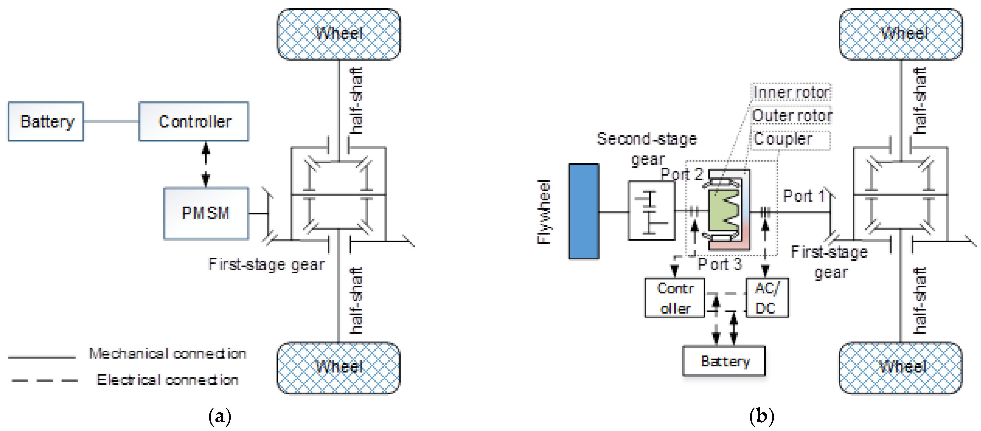
2. Brake Energy Recovery System

2.1. Two-Scenario Structure

The PMSM-based BERS is shown in Figure 2a, wherein the permanent magnet synchronous motor (PMSM) is connected with the differential mechanically through the first gear pair. The structure of the EC-BERS is shown in Figure 2b, wherein the electromagnetic couplers replace the permanent magnet synchronous motor and are arranged between the flywheel and wheel. A more detailed description can be found in Section 3.1. When the vehicle decelerates, the wheel drives the flywheel to rotate after increasing by half shaft, differential, first-stage gear, electromagnetic coupler and second-stage gear, storing partial kinetic energy in the flywheel directly.

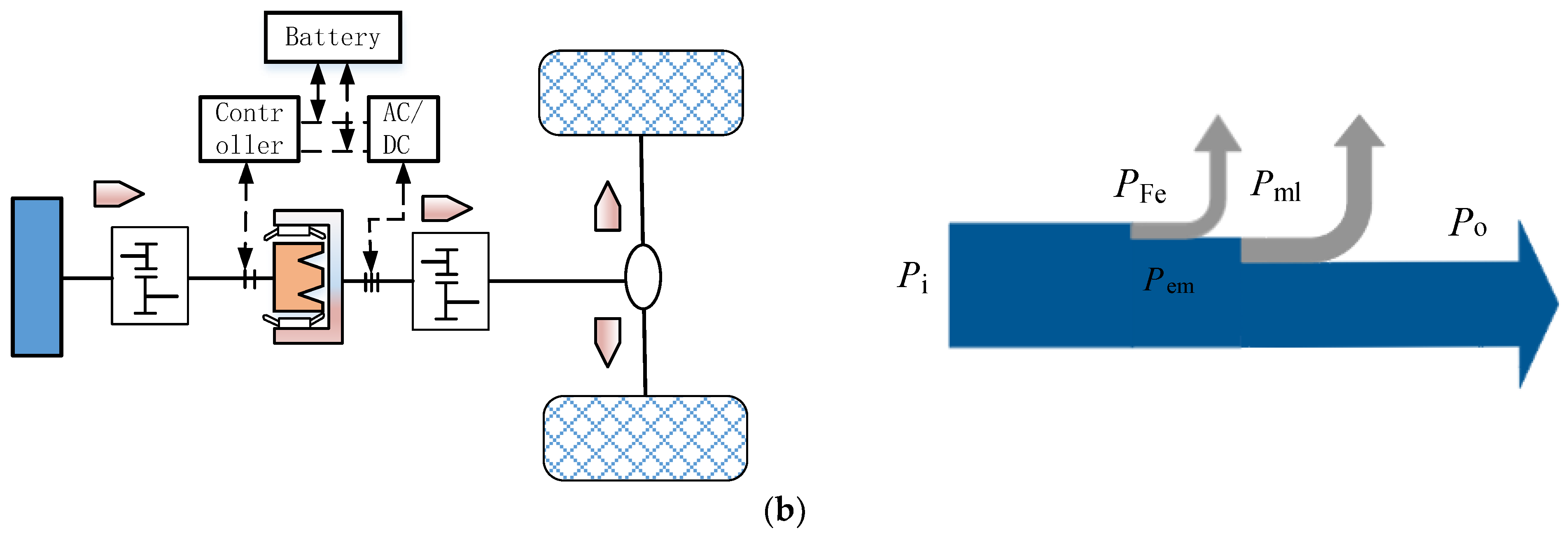
2.2. Powertrain Power Flow

In order to describe the energy transfer of the system quantitatively, it is assumed that the active power from or transmitted to the outer rotor shaft is Po, and the electromagnetic power, iron-loss, mechanical power, slip power, mechanical-loss, electric machine-losses and battery-losses are Pme, PFe, Pmech, Ps, Pml, Pel and Pbl [32], respectively. The active power from or transmitted to the inner rotor shaft is Pi. For the EC-BERS, the vehicle operating states include start-up, acceleration, cruise, deceleration and stop. In order to highlight the power–torque–speed characteristics of the proposed system, this section mainly demonstrates the power-flow under the deceleration and acceleration states. In fact, the flywheel’s speed can be zero at start-up if the vehicle is stationary for a long time. However, if the vehicle slows to a stop for a short time, the initial speed of the flywheel on the next start may not be zero, due to the previous kinetic energy capture. In Section 4.2, the initial state of the flywheel conforms to the second case, with a speed of 4395 rpm. When the vehicle stops, the outer rotor is at rest. At this time, if the flywheel rotates, the electromagnetic coupler acts as a generator, and current will be induced in the outer rotor winding to charge the battery through AC/DC.
In the deceleration state, part of the vehicle kinetic energy is stored in the flywheel through the two-gear pairs. Figure 3a shows the flywheel energy storage device and represents the energy conversion process in which the outer rotor angular velocity is greater than the inner rotor. The mechanical power (Pi) is stored in the flywheel through the second-stage gear, and the magnetic power (Pe) is stored in the battery. Assuming a situation where the angular velocity of the outer rotor is about same as the inner rotor, the slip power is approximately zero, as shown in Figure 3b.
Under the acceleration state, the energy stored in the flywheel releases on the rear wheel. Figure 4a represents the energy conversion process in which the angular velocity of the inner rotor is greater than the outer rotor. The mechanical power of the electromagnetic coupler acts on the rear wheel after the first-stage gear decelerates, and the power Pe is stored in the battery via the AC/DC. Figure 4b shows the energy conversion process when ωo = ωi.

3. Powertrain Modeling

3.1. Electromagnetic Coupler Overview

The electromagnetic coupler is a dual mechanical port motor, wherein the electrical port is connected to the battery through the converter, the outer rotor is connected to the rear wheel, and the inner rotor is connected to the flywheel, as shown in Figure 2b. Therefore, kinetic energy can be directly transferred from one mechanical port to another [33,34,35,36,37]. It follows the same electromagnetic rules as a normal motor. The amplitudes of torque produced on port 1 and port 2 are same. As long as there is relative movement between the mechanical ports, the magnetic flux of the rotor will change repeatedly, inducing currents in the outer rotor windings. Meanwhile, the amount of power transmitted through the mechanical port is determined by the electrical port. If the inner rotor is fixed, the electromagnetic coupler is an ordinary motor and its mathematical model in the dq coordinate system is as follows. Physical quantity name and symbol is given in Abbreviations.
u oq = R r i oq + ψ ˙ oq + p ( ω o ω i ) ψ od u od = R r i od + ψ ˙ od p ( ω o ω i ) ψ oq ψ od = L m i f + L od i od ψ oq = L oq i oq T e = 1.5 p ( ψ od i oq ψ oq i od )
T mo = J o d ω o d t + B o ω o + T eo T mi = J i d ω i d t + B i ω i + T ei T eo = T ei = 1.5 p L od L oq i oq i od L m i f i oq T eo = T ei = T e

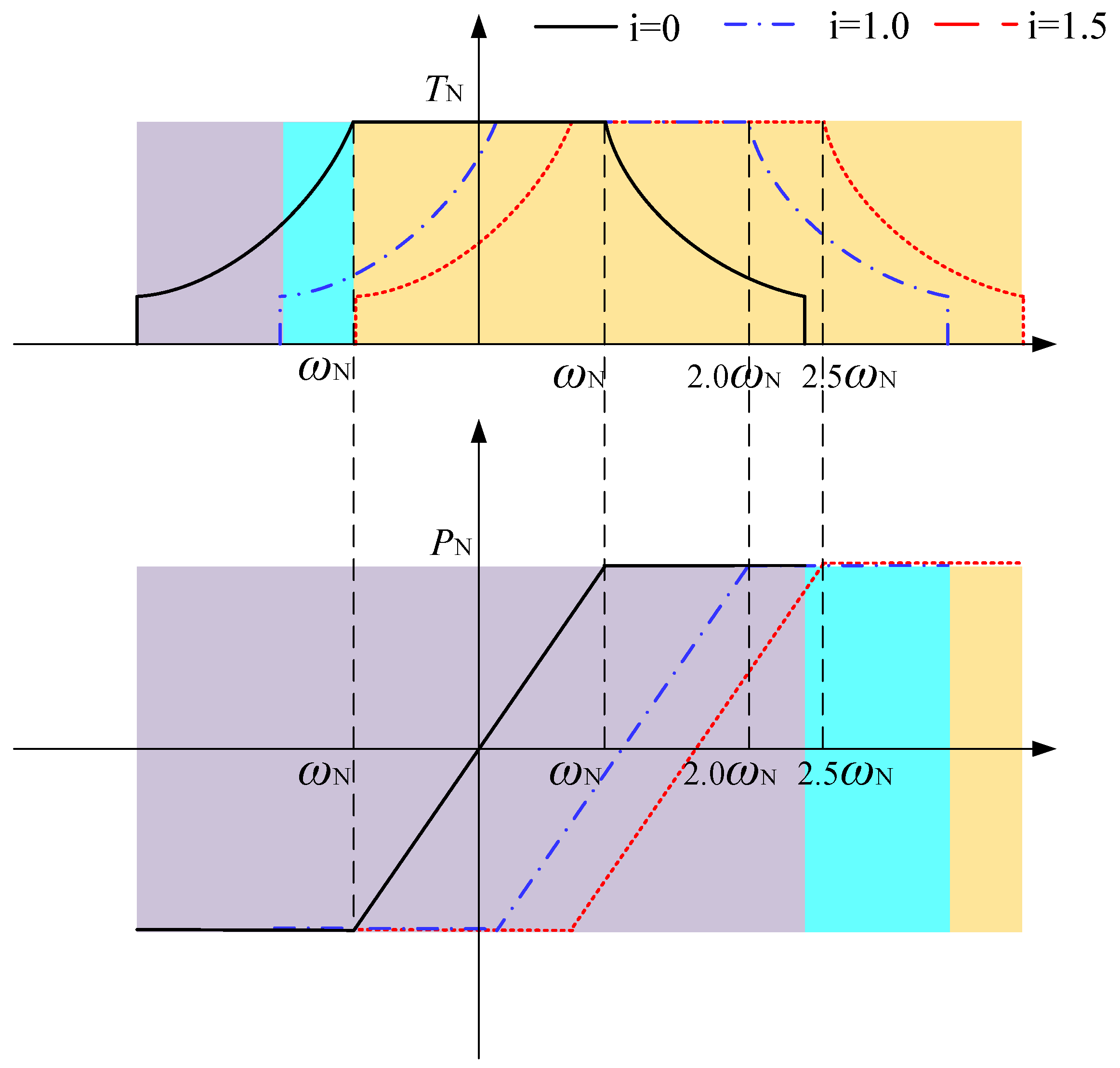
3.2. Power Characteristics

In order to describe the power characteristics of the EC-BERS quantitatively, the slip angular velocity and slip power are defined as Δ ω, Ps. The angular velocity, power and torque of the electromagnetic coupler at rated state are ωN, PN and TN. The relationship between variables satisfies the following equation:
Δ ω = ω o ω i P N = T N ω N
It is assumed that the electromagnetic coupler works at the rated torque and meets ωi = i ωN, ωo = (i + 1) ωN and i ≥ 0. The power of the inner and outer rotor, slip power and slip angular velocity of the coupler is as follows:
P o = ( i + 1 ) T N ω N P i = i T N ω N P s = P o P i = P N Δ ω = ω o ω i = ω N
Table 1 shows the power, torque and speed of the mechanical ports of the electromagnetic coupler when i = 0, 1.0 and 1.5. When i = 0, it means the inner rotor is fixed, and the electromagnetic coupler is equivalent to an ordinary motor. The T-ω and P-ω curves are shown as the purple area in Figure 5. When i > 0, the inner rotor is unfixed, and the electromagnetic coupler is equivalent to a double-mechanical motor. Due to the rotation of the inner rotor shaft, the induced voltage on the winding is reduced, and the torque–speed characteristics of the coupler move right, where i = 1.0 corresponds to the blue region, and i = 1.5 corresponds to the yellow region, as shown in Figure 5.
Although the traditional electric drive system has good acceleration performance at low speed, it has the problem of insufficient driving torque because it works in a constant power region at high speed. On the other hand, when traditional electric vehicles brake at high speed, the regenerative braking force of the motor is limited by the available output torque of the motor. It can be seen from the T-ω characteristics in Figure 5 that the electromagnetic coupling braking energy recovery system can give full play to the maximum torque under different speed ranges, that is, the working point of the system changes and moves to the high-speed zone. According to Formula (4), assuming that the EC-BERS operates at rated torque, the power transferred by the mechanical ports is much greater than its rated power. The flywheel recovery power from the wheels is not limited by the motor rated power, and the energy is stored in the form of mechanical energy directly. As a result, only the slip energy needs to be dealt with in electrical form and stored in the battery.

4. A Typical Case Study

The two scenarios given in Figure 2 will be discussed. In scenario one, a conventional PMSM-based BERS is used to capture braking energy. In scenario two, the EC-BERS substitutes for the PMSM-based BERS to capture the same braking deceleration rates as scenario one. In order to make the comparison more convincing, the parameters between the PMSM and the electromagnetic coupler are set as the same in Matlab/Simulink, shown in Table 2. For a typical family car, the mass of the flywheel is about 10 to 15 kg, with a diameter of about 40 cm, and its inertia is about 0.2 to 0.3 kg·m2. With the data as reference, the inertia of the flywheel in the proposed system is set as 0.3 kg · m2. As the composite rotor application, the flywheel can meet the requirements of kinetic energy storage with a smaller inertia (or mass). For example, a 10 kg idealized rim made of IM9/epoxy has a maximum kinetic energy of 2570 W · h, about 9.48 times that of steel 4340 [23]. Therefore, the composite rotor has great application value for the vehicle. In the process of vehicle deceleration–cruise, the PMSM and electromagnetic coupler all operate at rated torque to obtain a larger braking torque. According to the voltage equation in Formula (1), the dq components of the current are coupled. In order to realize current decoupling, the decoupling feedforward control strategy is adopted. Based on the above methods, the control block diagram of the electromagnetic coupler is established, as shown in Figure 6.

4.1. PMSM Based BERS

A conventional PMSM-based BERS, as shown in Figure 2a, serves as the power system for an electric vehicle. When the vehicle slows down, the PMSM can recover part of the braking energy. Figure 7 simulates the energy conversion process of the PMSM-based BERS when the vehicle slows down to 49 km/h at an initial speed of 80 km/h. At the beginning of deceleration, the wheel speed is 671.5 rpm (PMSM is spinning at 2686 rpm). At this moment, the driver decides to slow down the vehicle at rated torque. After 5.42 s, the wheel speed decreases to 412.5 rpm. Due to the PMSM rated speed being 1750 rpm, it works in the constant power zone when the speed is higher than 1750 rpm, as shown in Figure 7a. During this process, the SOC increased from 70% to 71.03%, and the battery open-circuit voltage from 113.605 V to 113.658 V. The controller dealt with 28.26 kJ energy which is stored in the battery.

4.2. EC-BERS

In this scenario, the conventional PMSM-based BERS is replaced by the proposed EC-BERS. For the EC-BERS, Figure 8 simulates the energy conversion process of the system when the vehicle is cruising at an initial speed of 80 km/h and decelerating to 49 km/h.
As shown in Figure 8a, the initial outer rotor speed is 2686 rpm, which means that the vehicle is cruising at 80 km/h. The inner rotor speed is 879 rpm, which means that the flywheel speed is 4395 rpm. At this moment, −30 N · m is applied to the electromagnetic coupler, and the vehicle speed reaches 49 km/h within 5.42 s. The final flywheel speed increases from 4395 rpm to 8080 rpm. With consideration to Figure 7a and Figure 8c, a conclusion could be found here that the working point of the EC-BERS changes and moves to the high-speed zone compared with the PMSM-based BERS. This phenomenon happens because the PMSM, which is operating at high speeds, cannot provide maximum torque in real time. The electromagnetic coupling braking energy recovery system can give full play to the maximum torque under different speed ranges.
According to Figure 8b, the power absorbed by the flywheel starts from 2.76 to 5.13 kW. Meanwhile, the absorbed power from the vehicle is changing from −8.44 to −5.18 kW. The electrical port power from the electromagnetic coupler changes from 5.67 to 0.11 kW during a deceleration of 0 to 5.42 s, so we can draw an interesting conclusion that the power dealt with by the electrical port is smaller than that of the mechanical port (outer rotor). As a result, about 75.54 kJ energy absorbed from the vehicle is stored in the flywheel, which is about 2.67 times of the recovered energy in the battery in the PMSM-BERS. Table 3 evaluates two typical scenarios by setting same parameters. For EC-BERS, only 15.53 kJ needs to be dealt with by the electrical port, which is about 0.549 times that of the PMSM-based BERS, and the maximum power transferred by the mechanical port is 8.44 kW. According to Equation (4), i is 0.688. On the basis of satisfying the strengths of the rotors and bearings, the higher the initial deceleration speed, the greater this power, that is, the greater is i.

5. Test

5.1. Test Platform

For proof of this concept, the EC-BERS test platform was designed and tested. The test platform is shown in Figure 9, and the parameters of each component are shown in Table 4. In order to describe the implementation process of the test more clearly, an EC-BERS powertrain energy flow was marked in Figure 10.
This paper adopts the flywheel II to simulate the initial kinetic energy of the vehicle under dynamic conditions. When the flywheel II reaches the specified speed, the PMSM is powered off. At this point, the kinetic energy of flywheel II is the vehicle’s kinetic energy when it starts to slow down. Because the V-belt drive can buffer vibration absorption, prevent overload damage of test bench components and is easy to install, the whole test platform adopts the V-belt drive. In order to achieve different initial states for the flywheel II in the test, the inverter is used to control the driving motor, such as acceleration, deceleration, positive rotation, negative rotation and stop. When the flywheel II reaches a specified speed, the drive motor is powered off. The flywheel I directly stores the vehicle’s kinetic energy through the first-stage V-belt, the electromagnetic coupler and the second-stage V-belt.

5.2. Results Analysis

The initial speed of the flywheel II is 165.6 rad/s (outer rotor angular velocity is 199.2 rad/s) while the flywheel I is 46.9 rad/s (inner rotor angular velocity is 27.1 rad/s), as shown in Figure 11a. At this moment, −25 N∙m is applied to the outer rotor until its speed reaches 169.6 rad/s. Meanwhile, the reaction torque rises upward from the inner rotor until it reaches 163.35 rad/s.
Figure 11b,c show the input–output power applied to the electromagnetic coupler mechanical port. The flywheel absorbed power starts from 0.68 kW to 4.09 kW. Meanwhile, the absorbed power from the vehicle is changing from −4.98 kW to −4.24 kW. The electromagnetic coupler’s electrical port power changes from 4.31 kW to 0.16 kW during a deceleration of 0 to 6.4 s. Figure 11c,d present the energy of the electromagnetic coupler and flywheel. From the point of view of energy flow, 28.91 kJ is fed into the electromagnetic coupler, and 15.24 kJ is output as mechanical energy and eventually stored in the flywheel, as seen in Figure 11c. During the process, about 47.3 percent (13.67 kJ) of the initial energy has been temporarily stored in the battery. In theory, all the energy recovered by the PMSM-based BERS goes into the electromagnetic coupler and is stored in the battery, which results in high battery engagement. In fact, the power fed into the outer rotor is determined by the outer rotor speed when the electromagnetic coupler operates at the rated torque. The energy captured by the electrical port is related to the speed difference between the rotors. Therefore, a condition was chosen that could represent the power characteristics of the system during the experiment. Of course, this is not the only case.

6. Conclusions

Hybrid technology is a method used to improve vehicle efficiency and quality. As an assistant powertrain, the flywheel can meet the peak power requirements of HEV acceleration. During regenerative braking, flywheel systems can not only absorb high power, but can also be much more efficient than batteries. In this paper, the EC-BERS powertrain was introduced to reduce battery engagement, for which the operating principles were described in detail and a mathematical model was presented. In order to represent the characteristics of the EC-BERS more directly, a mathematical model of the PMSM-based BERS was also established. In the same deceleration–cruise conditions, two typical systems were compared. The results showed that the EC-BERS provided a bidirectional path for mechanical energy transfer between the flywheel and the vehicle. Only the slip energy needed to be dealt with in electrical form, which reduced the battery participation. Furthermore, the proposed system can give full play to the maximum torque under different speed ranges, especially in the high-speed zone. At last, a test platform was designed and tested to verify this concept.
In addition to the above research conclusions, there are some necessary issues that need to be further studied. For example, the gyroscopic effect occurs when the spin axis of a rapidly rotating object changes direction in space. In the proposed EC-BERS system, the rotation axis of the flywheel is along the longitudinal direction of the car body. When the direction of the car movement changes, the gyroscopic effect will appear. To eliminate this effect, a vehicle could be fitted with two flywheels with parallel axes that turn in opposite directions, just as a plane has a double helix that rotates at equal and opposite angular speeds. The gyroscopic effect on the plane’s motion would cancel each other out. Furthermore, the flywheel bearing will still be subjected to gyroscopic pressure, which is also a consideration for the future. The flywheel hybrid system is applied to cars as an auxiliary power source and its goal is to ensure that the vehicle has excellent fuel economy. However, the additional mass of the flywheel system conflicts with the goal of achieving lightweight vehicles. How to reasonably control the quality, cost, efficiency, power density and energy density of the flywheel hybrid powertrain to achieve the optimal cost performance under different goals still needs further study.

Author Contributions

Methodology, H.L. and J.C.; software, H.L.; validation, H.L. and S.S.; writing—original draft preparation, H.L.; writing—review and editing, H.L. and J.C. All authors have read and agreed to the published version of the manuscript.

Funding

This research was funded by the National Key Research and Development Program Project of China (Grant No. 2018YFE0207800-04) and the Fundamental Research Funds for the Central Universities of China (Grant No. 2572021DT79).

Institutional Review Board Statement

Not applicable.

Informed Consent Statement

Not applicable.

Data Availability Statement

The data presented in this study are available on request from the corresponding author.

Conflicts of Interest

The authors declare no conflict of interest.

Abbreviations

uoq, uodouter rotor qd components of voltage
ψoq, ψodouter rotor qd components of flux
Rrouter rotor resistance
ioq, iodouter rotor qd components of current
ifinner rotor excitation current
Lmmutual inductance between inner and out rotor
Loq, Lodouter rotor qd components of self-inductance
ωo, ωiangular velocity outer and inner rotor
pnumber of pole pairs
Teelectromagnetic torque
Tei, Teoelectromagnetic torque of inner and outer rotor
Tmi, Tmomechanical torque of inner and outer rotor
Bi, Bofriction of inner and outer rotor
Ji, Joinertia of inner and outer rotor
Pi, Popower of inner and outer rotor

References

  1. Scharf, C.A. The Crazy Scale of Human Carbon Emission. Available online: https://blogs.scientificamerican.com/life-unbounded/the-crazy-scale-of-human-carbon-emission/ (accessed on 26 April 2017).
  2. Concordia University. CO2 Emissions Cause Lost Labor Productivity. Available online: https://www.sciencedaily.com/releases/2019/10/191011131856.htm (accessed on 11 October 2019).
  3. IPPC Sixth Assessment Report. Climate Change 2021: The Physical Science Basis. Available online: https://www.ipcc.ch/report/ar6/wg1/ (accessed on 9 August 2021).
  4. British Petroleum (BP). Statistical Review of World Energy. 2020. Available online: https://www.bp.com/en/global/corporate/energy-economics/statistical-review-of-world-energy.html (accessed on 26 October 2021).
  5. Zhang, Y.; Chao, Q.; Chen, Y.; Zhang, J.; Wang, M.; Zhang, Y.; Yu, X. China’s Carbon Neutrality: Leading Global Climate Governance and Green Transformation. Chin. J. Urban Environ. Stud. 2021, 9, 2150019. [Google Scholar] [CrossRef]
  6. Chen, H.S.; Liu, C.; Xu, Y.J.; Yue, F.; Liu, W.; Yu, Z.H. The strategic position and role of energy storage under the goal of carbon peak and carbon neutrality. Energy Storage Sci. Technol. 2021, 10, 1477–1485. [Google Scholar] [CrossRef]
  7. Automotive Industry In-Depth Report 2021: Analysis of Investment Opportunities in the Automotive Industry in the Context of Carbon Neutrality. Available online: https://www.docin.com/p-2657760630.html (accessed on 30 March 2021).
  8. China SAE. Energy Saving and New Energy Vehicle Technology Roadmap 2.0; China SAE: Beijing, China, 2020. [Google Scholar]
  9. Changzhou Haike New Energy. Core Technology; Changzhou Haike New Energy: Changzhou, China, 2012; Available online: http://www.chk-net.com/en/product.asp?id=12 (accessed on 25 November 2020).
  10. De Oliveira, J.G. Power Control Systems in a Flywheel Based All-Electric Driveline. Ph.D. Thesis, Uppsala University, Uppsala, Sweden, 2011. [Google Scholar]
  11. Hedlund, M.; Lundin, J.; De Santiago, J.; Abrahamsson, J.; Bernhoff, H. Flywheel Energy Storage for Automotive Applications. Energies 2015, 8, 10636–10663. [Google Scholar] [CrossRef] [Green Version]
  12. de Oliveira, J.G.; Schettino, H.; Gama, V.; Carvalho, R.; Bernhoff, H. Study on a doubly-fed flywheel machine-based driveline with an AC/DC/AC converter. IET Electr. Syst. Transp. 2012, 2, 51–57. [Google Scholar] [CrossRef]
  13. Itani, K.; De Bernardinis, A.; Khatir, Z.; Jammal, A. Comparative analysis of two hybrid energy storage systems used in a two front wheel driven electric vehicle during extreme start-up and regenerative braking operations. Energy Convers. Manag. 2017, 144, 69–87. [Google Scholar] [CrossRef]
  14. Dhand, A.; Pullen, K. Review of flywheel based internal combustion engine hybrid vehicles. Int. J. Automot. Technol. 2013, 14, 797–804. [Google Scholar] [CrossRef] [Green Version]
  15. Atienza, A.H.; Carino, A.; Jacinto, N. Mechanical Interface of Flywheel Kinetic Energy Recovery System on Motorized Tricycles. J. Phys. Conf. Ser. 2020, 1519, 012001. [Google Scholar] [CrossRef]
  16. Jingang, G.; Dong, H.; Sheng, W.; Chao, T. Optimum control strategy of regenerative braking energy for electric vehicle. J. Jiangsu Univ. (Nat. Sci. Ed.) 2018, 39, 132–138. [Google Scholar]
  17. Ehsani, M.; Gao, Y.; Longo, S.; Ebrahimi, K.M. Modern Electric, Hybrid Electric, and Fuel Cell Vehicles; CRC Press: Boca Raton, FL, USA, 2018. [Google Scholar]
  18. Mutoh, N.; Nakano, Y. Dynamics of Front-and-Rear-Wheel Independent-Drive-Type Electric Vehicles at the Time of Failure. IEEE Trans. Ind. Electron. 2012, 59, 1488–1499. [Google Scholar] [CrossRef]
  19. Wu, J.; Xu, Z.; Zhang, F.; Tong, N. Electromagnetic design of high-speed permanent magnet synchronous motor for flywheel energy storage system. J. Phys. Conf. Ser. 2021, 1887, 012044. [Google Scholar] [CrossRef]
  20. Dougal, R.A.; Liu, S.; White, R.E. Power and life extension of battery-ultracapacitor hybrids. IEEE Trans. Compon. Packag. Technol. 2002, 25, 120–131. [Google Scholar] [CrossRef] [Green Version]
  21. Rajagopal, S.; Vallikkattil, R.P.; Ibrahim, M.M.; Velev, D.G. Electrode Materials for Supercapacitors in Hybrid Electric Vehicles: Challenges and Current Progress. Condens. Matter 2022, 7, 6. [Google Scholar] [CrossRef]
  22. Ortuzar, M.; Moreno, J.; Dixon, J. Ultracapacitor-Based Auxiliary Energy System for an Electric Vehicle: Implementation and Evaluation. IEEE Trans. Ind. Electron. 2007, 54, 2147–2156. [Google Scholar] [CrossRef]
  23. Hansen, J.G.R.; O’kain, D.U. An Assessment of Flywheel High Power Energy Storage Technology for Hybrid Vehicles; Oak Ridge National Laboratory: Oak Ridge, TN, USA, 2012. Available online: https://info.ornl.gov/sites/publications/Files/Pub31707.pdf (accessed on 10 June 2021).
  24. Pullen, K.R.; Ellis, C.W.H. Kinetic energy storage for vehicles. In Proceedings of the IET—The Institution of Engineering and Technolgy Hybrid Vehicle Conference, Coventry, UK, 12–13 December 2006; pp. 91–108. [Google Scholar]
  25. Ehsani, M.; Singh, K.V.; Bansal, H.O.; Mehrjardi, R.T. State of the Art and Trends in Electric and Hybrid Electric Vehicles. Proc. IEEE 2021, 109, 967–984. [Google Scholar] [CrossRef]
  26. Chabchoub, M.H.; Trabelsi, H. Improving the efficiency of the energy source of electric vehicles. In Proceedings of the 2020 17th International Multi-Conference on Systems, Signals & Devices (SSD), Sfax, Tunisia, 20–23 July 2020; pp. 410–416. [Google Scholar] [CrossRef]
  27. Ahin, M.E.; Blaabjerg, F.; Sangwongwanich, A. A Comprehensive Review on Supercapacitor Applications and Developments. Energies 2022, 15, 674. [Google Scholar] [CrossRef]
  28. Rufer, A. The Dream of Efficient Energy Storage-From BESS, KERS & Co. to the Hybrid Power Plant. In Proceedings of the 19th European Conference on Power Electronics and Applications (EPE’17 ECCE Europe), Warsaw, Poland, 11–14 September 2017. [Google Scholar] [CrossRef]
  29. Guney, M.S.; Tepe, Y. Classification and assessment of energy storage systems. Renew. Sustain. Energy Rev. 2017, 75, 1187–1197. [Google Scholar] [CrossRef]
  30. Hadjipaschalis, I.; Poullikkas, A.; Efthimiou, V. Overview of current and future energy storage technologies for electric power applications. Renew. Sustain. Energy Rev. 2009, 13, 1513–1522. [Google Scholar] [CrossRef]
  31. Vazquez, S.; Lukic, S.M.; Galvan, E.; Franquelo, L.G.; Carrasco, J.M. Energy Storage Systems for Transport and Grid Applications. IEEE Trans. Ind. Electron. 2010, 57, 3881–3895. [Google Scholar] [CrossRef] [Green Version]
  32. Tang, T.H. Fundamentals of Motor and Drive; China Machine Press: Beijing, China, 2016. [Google Scholar]
  33. Cai, H.; Xu, L. Modeling and Control for Cage Rotor Dual Mechanical Port Electric Machine–Part I: Model Development. IEEE Trans. Energy Convers. 2015, 30, 957–965. [Google Scholar] [CrossRef]
  34. Ershad, N.F.; Mehrjardi, R.T.; Ehsani, M. Efficient Flywheel-Based All-Wheel-Drive Electric Powertrain. IEEE Trans. Ind. Electron. 2021, 68, 5661–5671. [Google Scholar] [CrossRef]
  35. Xia, L.; Jiang, H.B. Design and Steady-State Performance of a Novel Winding Type Permanent Magnet Coupling with Slip Power Recovery Function. Math. Probl. Eng. 2017, 2017, 3141089. [Google Scholar] [CrossRef]
  36. Nasiri, H.; Radan, A.; Ghayebloo, A.; Ahi, K. Dynamic modeling and simulation of transmotor based series-parallel HEV applied to Toyota Prius 2004. In Proceedings of the 10th International Conference on Environment and Electrical Engineering, Rome, Italy, 8–11 May 2011. [Google Scholar] [CrossRef]
  37. Jiang, H.B.; Tang, B.; Xu, Z.; Geng, G.-Q. Electromagnetic and Torque Characteristics of Electromagnetic Slip Coupling Applied to Hydraulic Power Steering System for Heavy-Duty Vehicles. J. Comput. Theor. Nanosci. 2015, 12, 1069–1075. [Google Scholar] [CrossRef]
Figure 1. CO2 emissions in some countries (2009–2019) [4].
Sustainability 14 08076 g001
Figure 2. Structure of braking energy recovery system: (a) PMSM-based BERS; (b) EC-BERS.
Sustainability 14 08076 g002
Figure 3. Energy conversion process under deceleration conditions: (a) ω o > ω i ; (b) ω o = ω i .
Sustainability 14 08076 g003
Figure 4. Energy conversion process under acceleration conditions: (a) ω o < ω i ; (b) ω o = ω i .
Sustainability 14 08076 g004aSustainability 14 08076 g004b
Figure 5. Electrical port characteristics of electromagnetic coupler.
Sustainability 14 08076 g005
Figure 6. Control block diagram. Notes: ABC is the three-phase winding of the outer rotor, iod*, ioq* are the expected value of dq component of current, uod*, uoq* are the expected value of dq component of voltage, udc is output voltage of dc side.
Sustainability 14 08076 g006
Figure 7. Scenario one simulation results: (a) PMSM rotor speed curve; (b) SOC curve of battery.
Sustainability 14 08076 g007
Figure 8. Scenario two simulation results: (a) mechanical port speed; (b) mechanical port power; (c) mechanical port torque; (d) electrical port.
Sustainability 14 08076 g008
Figure 9. EC-BERS test platform.
Sustainability 14 08076 g009
Figure 10. EC-BERS powertrain energy flow (test platform).
Sustainability 14 08076 g010
Figure 11. Experimental results: (a) mechanical port speed; (b) mechanical port power; (c) electrical port; (d) flywheel energy.
Sustainability 14 08076 g011
Table 1. Power transfer characteristics of mechanical ports of electromagnetic coupler.
Operative StateiωiωoPiPo
The inner rotor is fixed00ωN0PN
The inner rotor is removed from fixation1.0ωN2 ωNPN2.0 PN
1.51.5 ωN2.5 ωN1.5 PN2.5 PN
Table 2. Case study parameters.
Vehicle ParametersUnitValue
Masskg1650
Wheel radiusm0.316
Flywheel ParametersUnitValue
Inertiaskg · m20.3
Maximum speedrpm25,000
Initial speedrpm4395
Masskg15
Gear Pair Parameters UnitValue
First stage -1:4
Second stage -1:5
PMSM ParametersUnitValue
Rated powerkW5.5
Rated speedr · min−11750
Rated torqueN · m30.0
Battery ParametersUnitValue
CapacityW · h780
SOC%70
Open-circuit VoltageV120
Electromagnetic Coupler ParametersUnitValue
Rated powerkW5.5
Rated speedr · min−11750
Rated torqueN · m30.0
Table 3. Results for two typical scenarios.
PMSM-Based BERSEC-BERSChanges
Times (s)5.425.420
Power (kW)5.08.44+3.44
Energy dealt with battery (kJ)28.2615.53−12.73
Energy dealt with flywheel (kJ)-75.54-
Notes: “Power” refers to the power input to PMSM or electromagnetic coupler (Po) from wheels.
Table 4. Experimental parameters.
ParametersUnitValue
Flywheel I inertiaskg · m22.99
Flywheel II inertiaskg · m24.82
First-stage V belt-1:1.20
Second-stage V belt-1:1.73
Torque sensor rangeNm0.1~100
Drive motor rated powerkW4.0
Drive motor rated speedr · min−12890
Drive motor rated torqueN · m13.2
Electromagnetic coupler rated power/kW4.0
Electromagnetic coupler rated speed/r · min−11528
Electromagnetic coupler rated torqueN · m25
Publisher’s Note: MDPI stays neutral with regard to jurisdictional claims in published maps and institutional affiliations.

