
Harmonics Minimisation in Non-Linear Grid System Using an Intelligent Hysteresis Current Controller Operated from a Solar Powered ZETA Converter

 , , ,
, , ,  and
and
Abstract
:1. Introduction
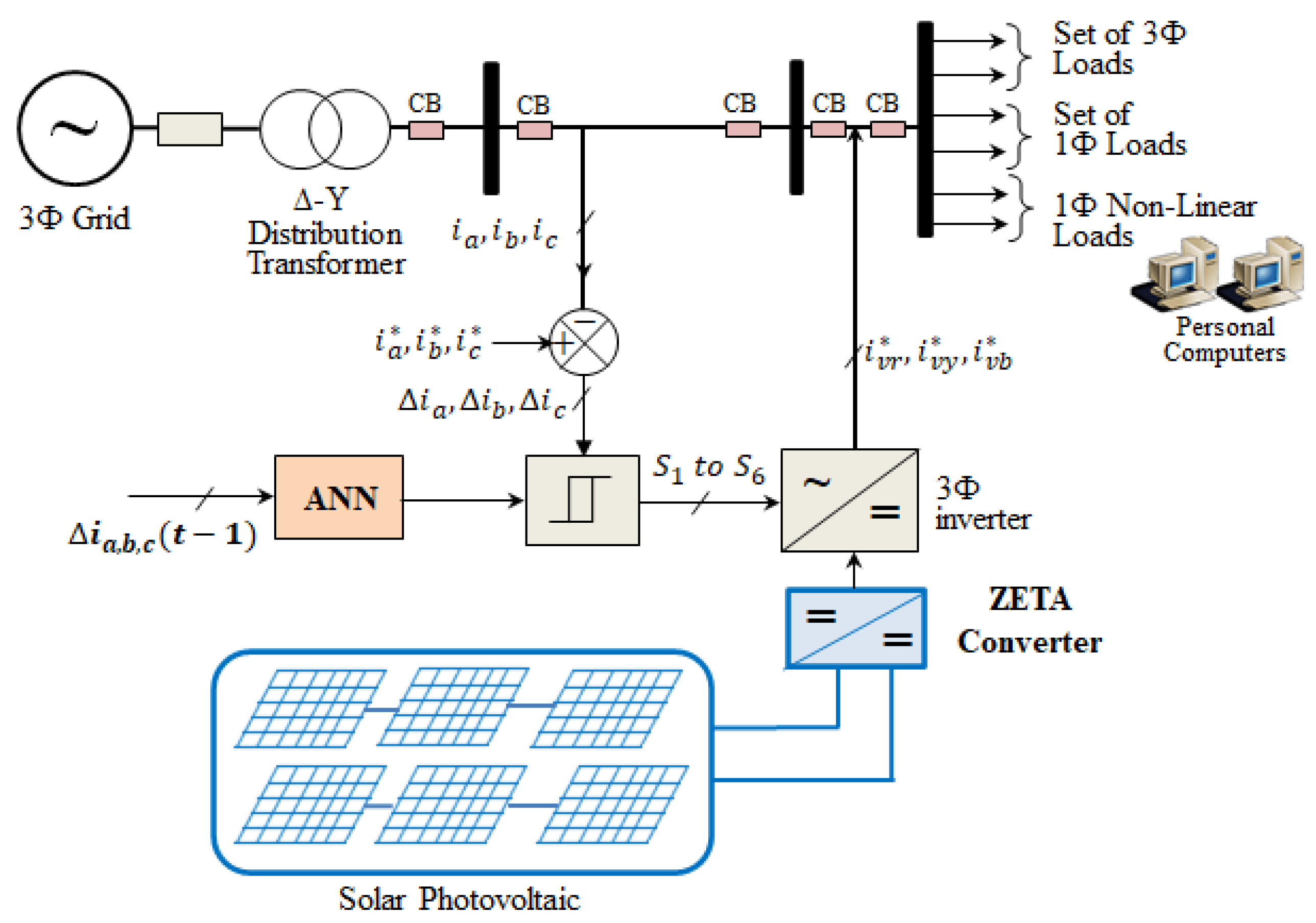
2. Proposed Model
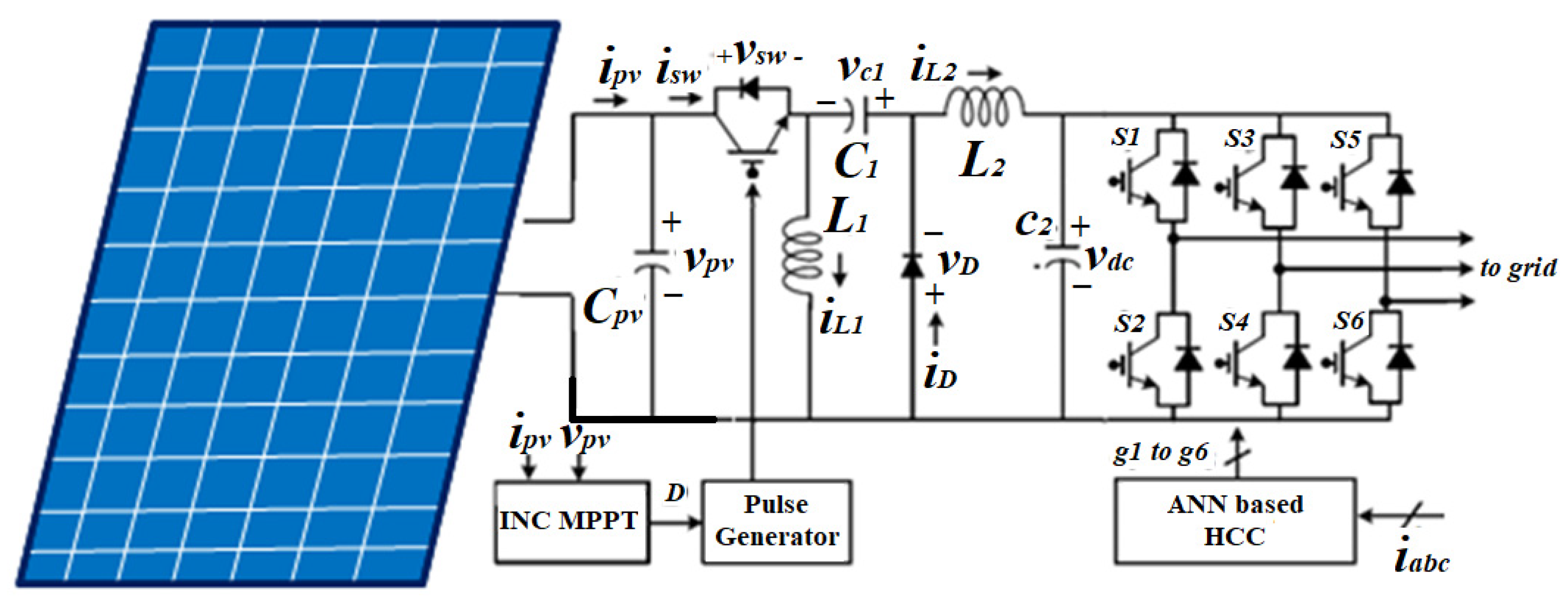
2.1. Modelling of the Solar PV
2.2. Modelling of ZETA Embedded Three-Phase Inverter
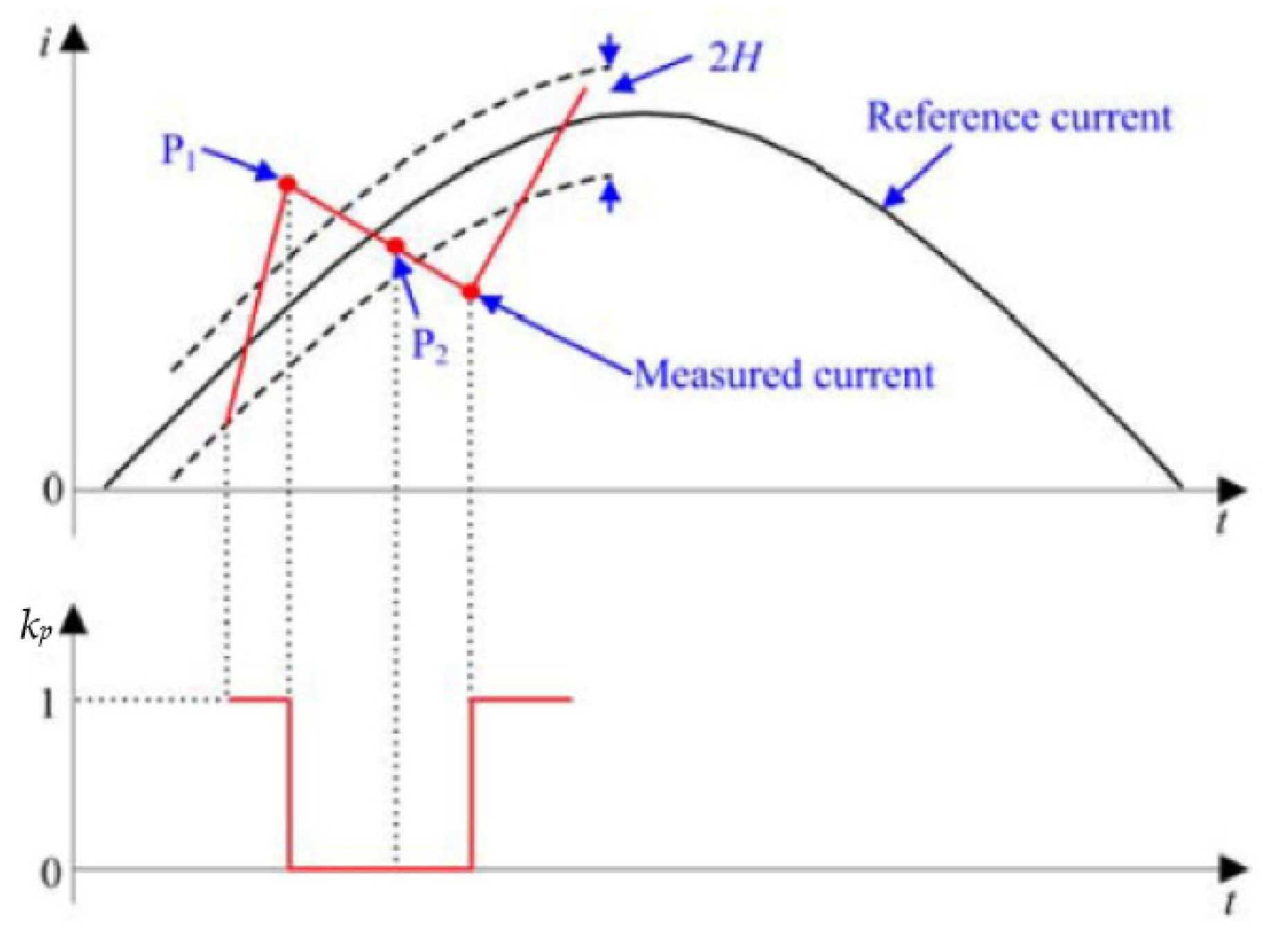
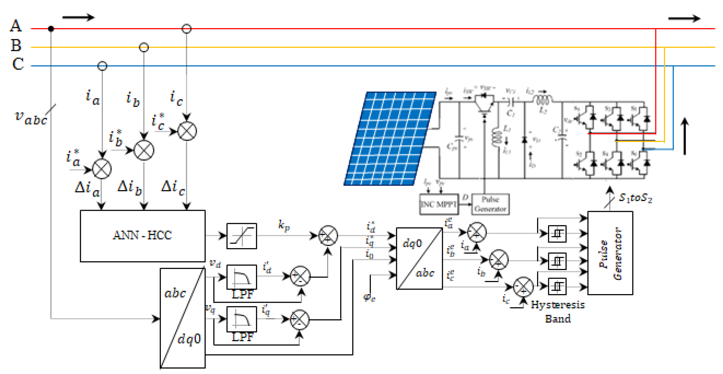
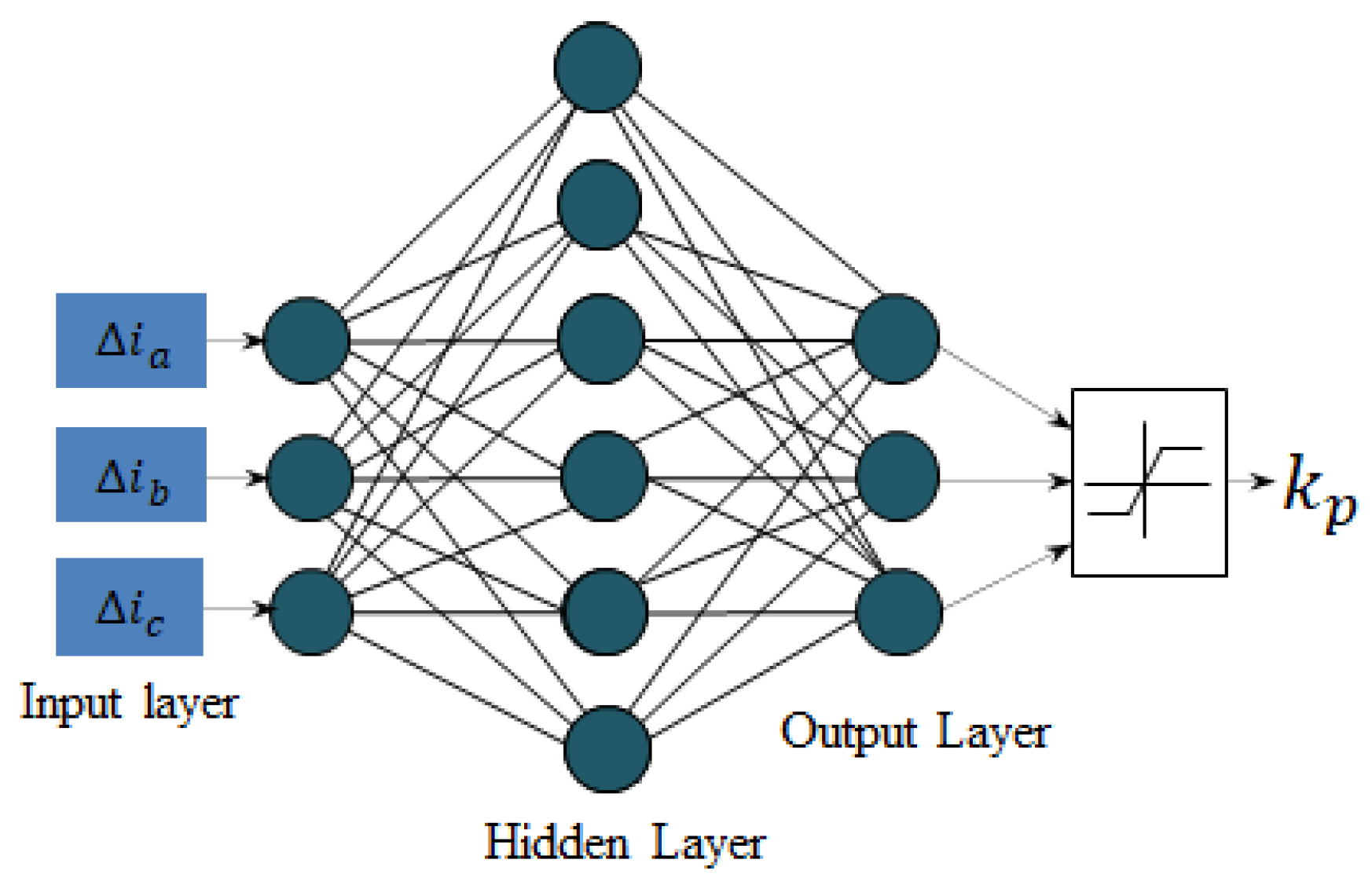
2.3. ANN-Based HCC Model
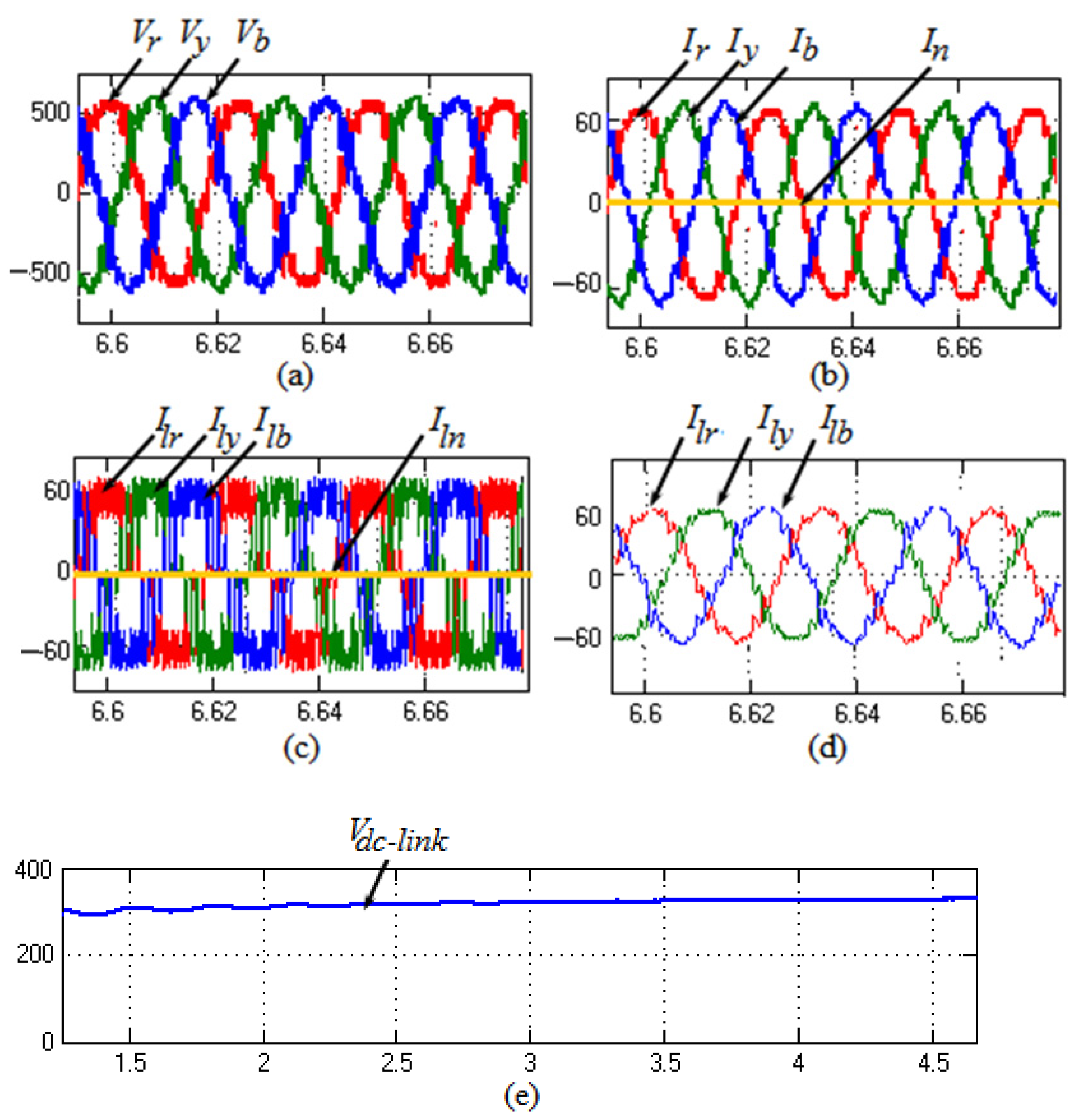
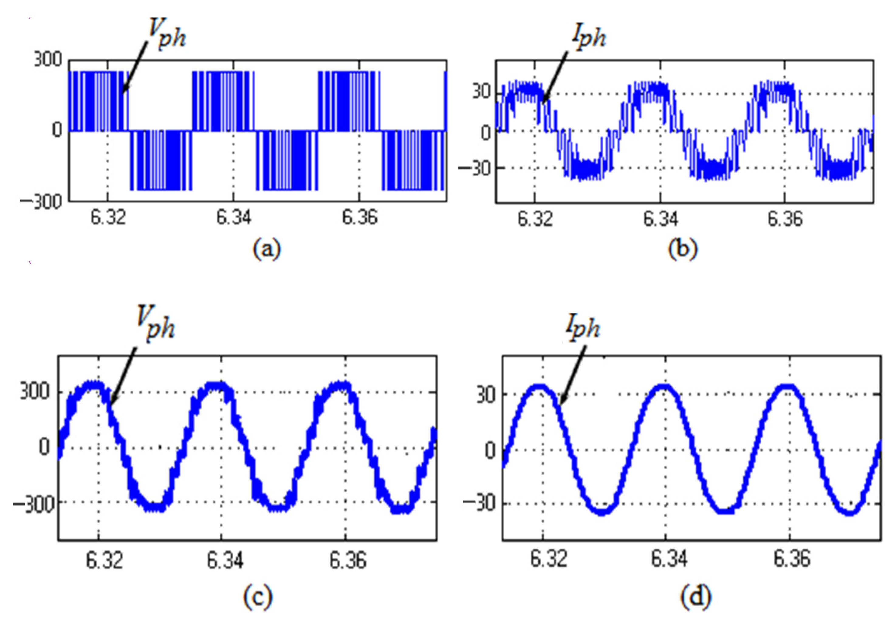
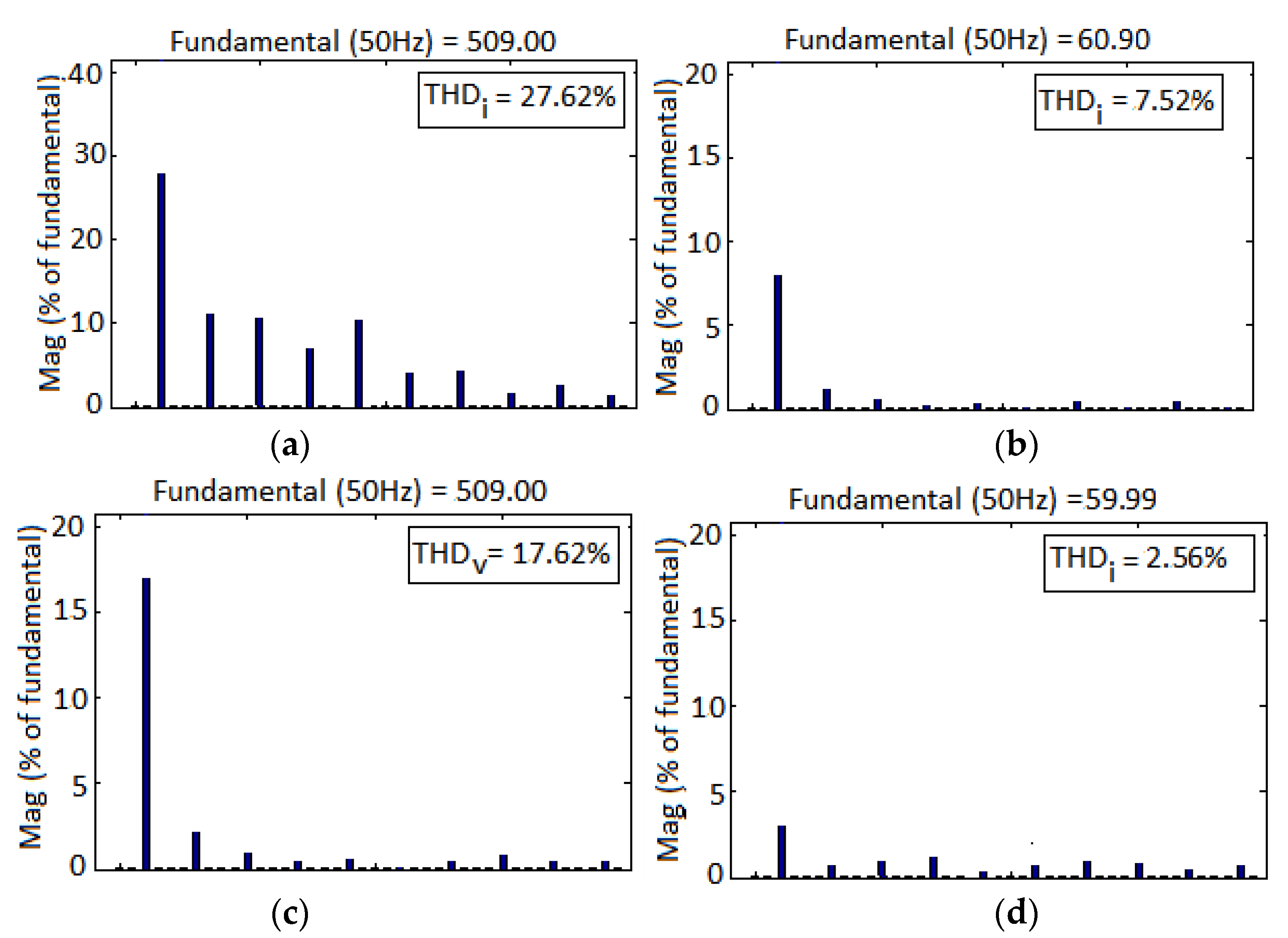
3. Simulation Results
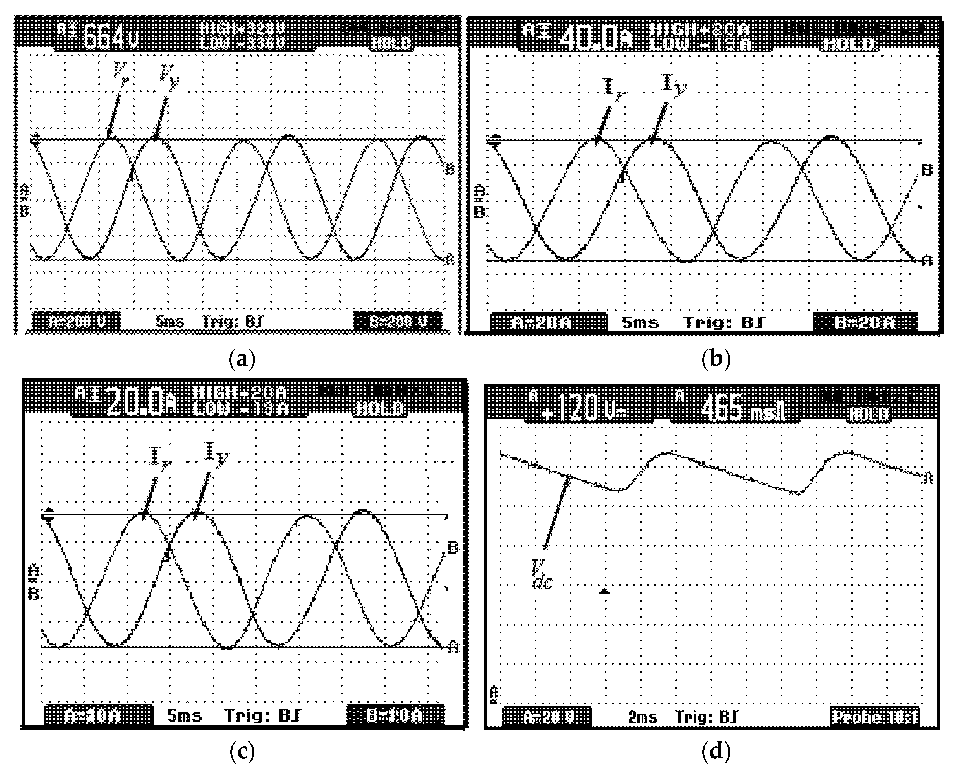
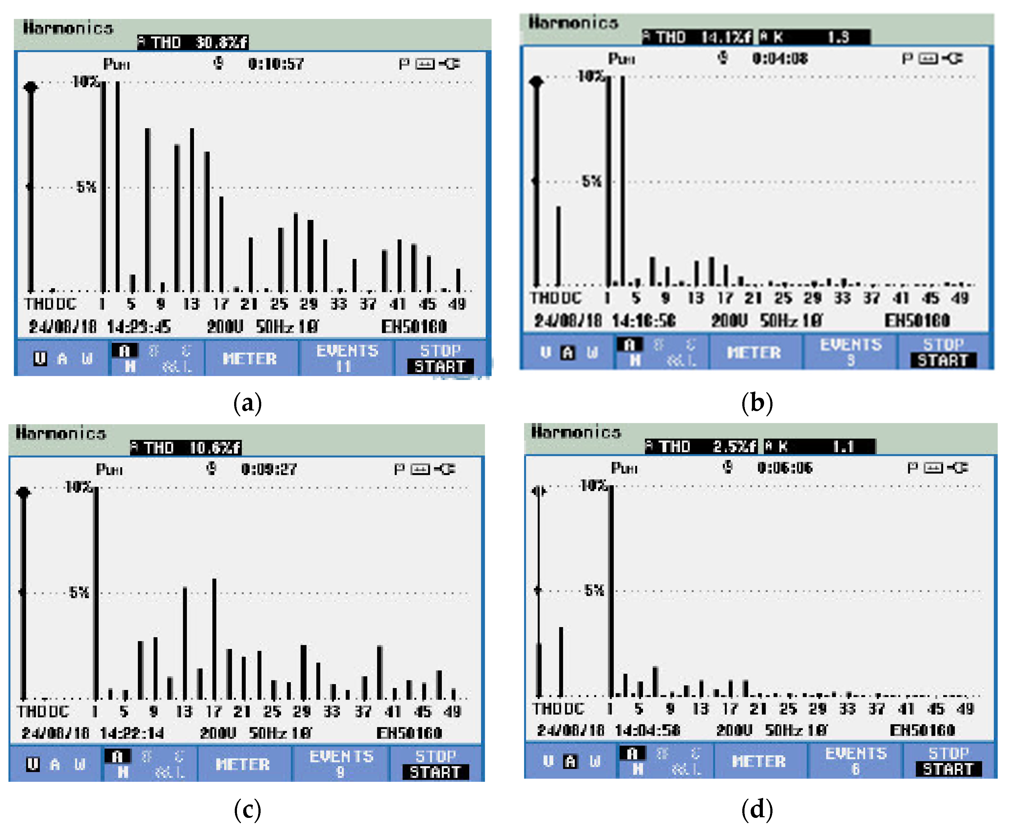
4. Experimental Validation
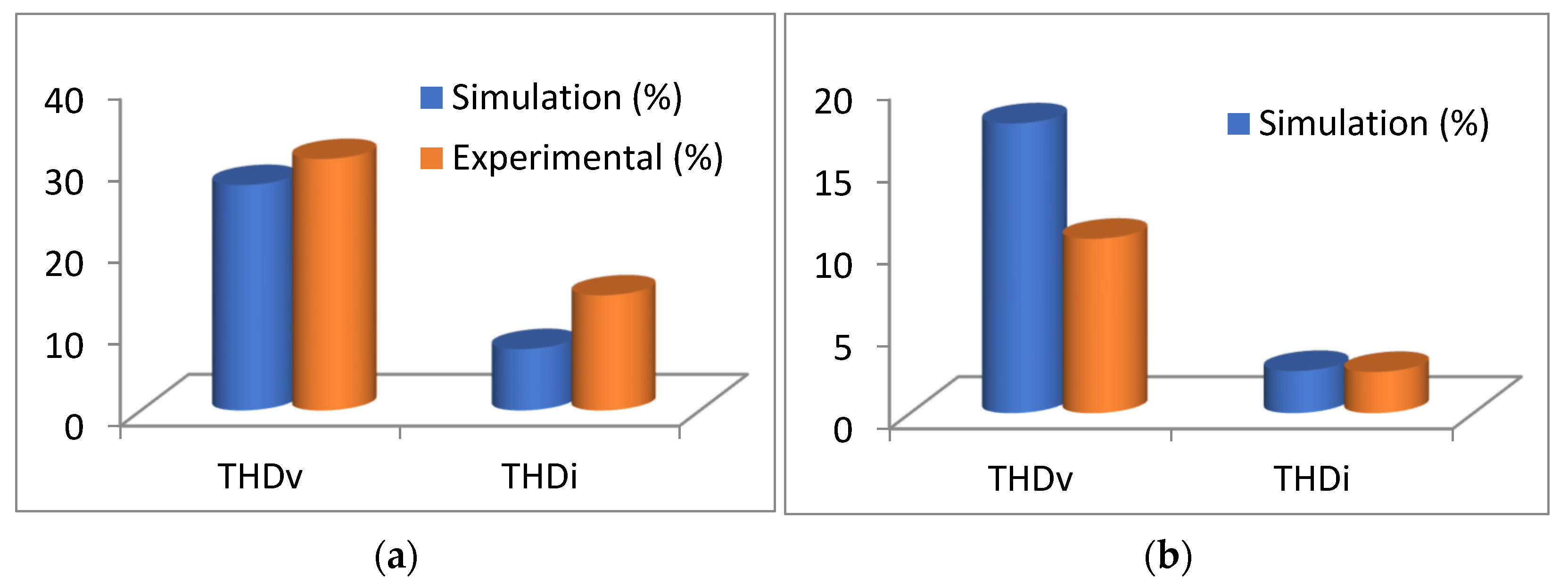
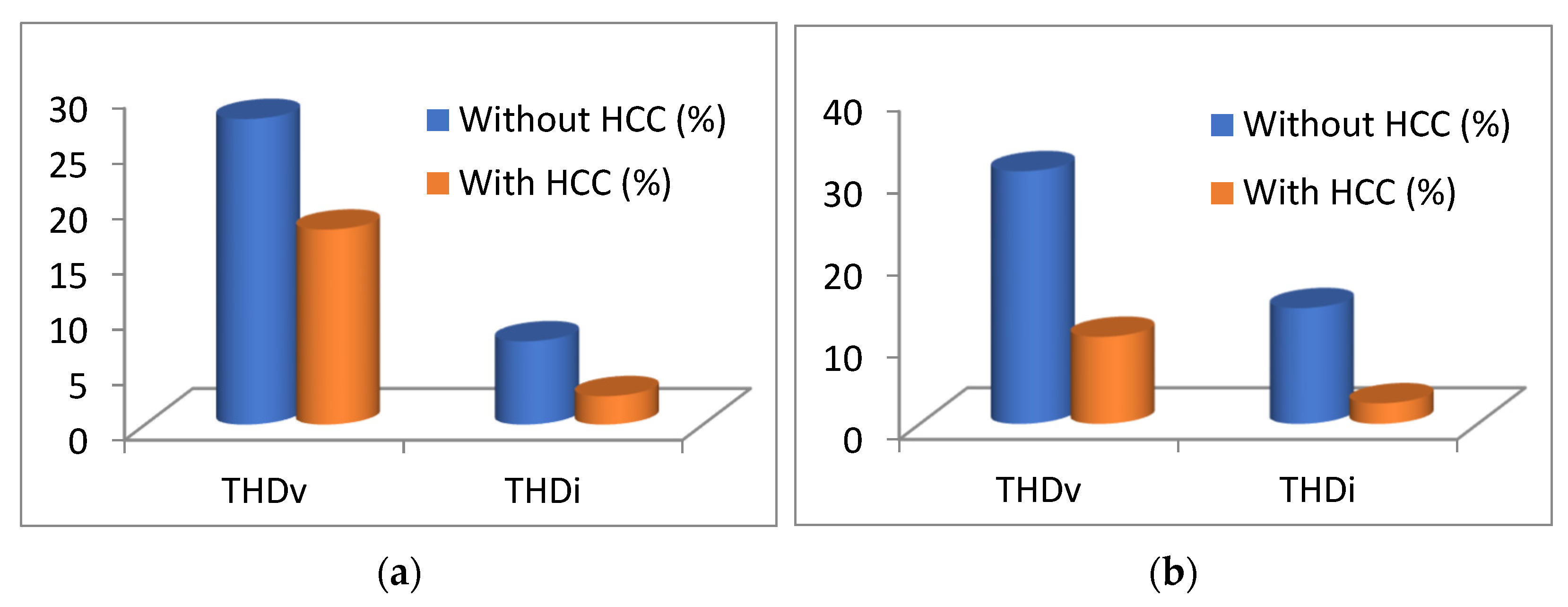
5. Comparative Analysis
6. Conclusions
Author Contributions
Funding
Institutional Review Board Statement
Informed Consent Statement
Data Availability Statement
Conflicts of Interest
References
- Venkatesan, C.; Kannadasan, R.; Alsharif, M.; Kim, M.-K.; Nebhen, J. Assessment and Integration of Renewable Energy Resources Installations with Reactive Power Compensator in Indian Utility Power System Network. Electronics 2021, 10, 912. [Google Scholar] [CrossRef]
- Venkatesan, C.; Kannadasan, R.; Alsharif, M.; Kim, M.-K.; Nebhen, J. A Novel Multiobjective Hybrid Technique for Siting and Sizing of Distributed Generation and Capacitor Banks in Radial Distribution Systems. Sustainability 2021, 13, 3308. [Google Scholar] [CrossRef]
- Venkatesan, C.; Kannadasan, R.; Ravikumar, D.; Loganathan, V.; Alsharif, M.H.; Choi, D.; Hong, J.; Geem, Z.W. Re-Allocation of Distributed Generations Using Available Renewable Potential Based Multi-Criterion-Multi-Objective Hybrid Technique. Sustainability 2021, 13, 13709. [Google Scholar] [CrossRef]
- Rajalakshmi, M.; Chandramohan, S.; Kannadasan, R.; Alsharif, M.; Kim, M.-K.; Nebhen, J. Design and Validation of BAT Algorithm-Based Photovoltaic System Using Simplified High Gain Quasi Boost Inverter. Energies 2021, 14, 1086. [Google Scholar] [CrossRef]
- Vora, S.; Bhatt, D. A Comprehensive Review of Harmonics Effects on Electrical Power Quality. Int. J. Eng. Dev. Res. 2014, 1, 15–21. [Google Scholar]
- Du, Q.; Gao, L.; Li, Q.; Li, T.; Meng, F. Harmonic Reduction Methods at D.C. Side of Parallel-Connected Multipulse Rectifiers: A Review. IEEE Trans. Power Electron. 2021, 36, 2768–2782. [Google Scholar]
- Hintz, A.; Prasanna, U.R.; Rajashekara, K. Comparative Study of the Three-Phase Grid-Connected Inverter Sharing Unbalanced Three-Phase and/or Single-Phase systems. IEEE Trans. Ind. Appl. 2016, 52, 5156–5164. [Google Scholar] [CrossRef]
- Sinvula, R.; Abo-Al-Ez, K.M.; Kahn, M.T.E. Harmonic Source Detection Methods: A Systematic Literature Review. IEEE Access 2019, 7, 74283–74299. [Google Scholar] [CrossRef]
- McBee, K.D.; Simoes, M. Evaluating the Long-Term Impact of a Continuously Increasing Harmonic Demand on Feeder-Level Voltage Distortion. IEEE Trans. Ind. Appl. 2013, 50, 2142–2149. [Google Scholar] [CrossRef]
- Garcia-Torres, F.; Vazquez, S.; Moreno-Garcia, I.; Gil-De-Castro, A.; Roncero-Sanchez, P.; Moreno-Munoz, A. Microgrids Power Quality Enhancement Using Model Predictive Control. Electronics 2021, 10, 328. [Google Scholar] [CrossRef]
- Alshehri, J.; Khalid, M. Power Quality Improvement in Microgrids Under Critical Disturbances Using an Intelligent Decoupled Control Strategy Based on Battery Energy Storage System. IEEE Access 2019, 7, 147314–147326. [Google Scholar] [CrossRef]
- Mosaad, M.I.; Ramadan, H. Power quality enhancement of grid-connected fuel cell using evolutionary computing techniques. Int. J. Hydrog. Energy 2018, 43, 11568–11582. [Google Scholar] [CrossRef]
- Kaushal, J.; Basak, P. Power quality control based on voltage sag/swell, unbalancing, frequency, THD and power factor using artificial neural network in P.V. integrated A.C. microgrid. Sustain. Energy Grids Netw. 2020, 23, 100365. [Google Scholar]
- Barik, P.K.; Shankar, G.; Sahoo, P.K. Power quality assessment of microgrid using fuzzy controller aided modified SRF based designed SAPF. Int. Trans. Electr. Energy Syst. 2019, 30, e12289. [Google Scholar] [CrossRef]
- Esmaeili, M.; Shayeghi, H.; Valipour, K.; Safari, A.; Sedaghati, F. Power quality improvement of multi-microgrid using improved custom power device called as distributed power condition controller. Int. Trans. Electr. Energy Syst. 2020, 30, e12259. [Google Scholar] [CrossRef]
- Salem, A.E.-S.; Salim, O.M.; Arafa, S.I. New triple-action controller for inverter power quality improvement. Comput. Electr. Eng. 2019, 81, 106543. [Google Scholar] [CrossRef]
- Shahbaz, R.; Ahmed, T.; Elavarasan, R.M.; Raju, K.; Waqas, M.; Subramaniam, U. Selective Harmonics Elimination in Multilevel Inverter Using Bio-Inspired Intelligent Algorithms. In Proceedings of the 2021 31st Australasian Universities Power Engineering Conference (AUPEC), Perth, Australia, 26–30 September 2021. [Google Scholar] [CrossRef]
- Haiya, Q.; Xu, Q.; Jun, Z.; Yuan, X. A robust GPS-based control scheme for power sharing and quality improvement in microgrid. Int. J. Electr. Power Energy Syst. 2020, 123, 106324. [Google Scholar]
- Jahan, S.; Biswas, S.; Hosain, K.; Islam, R.; Haq, S.; Kouzani, A.; Mahmud, M. An Advanced Control Technique for Power Quality Improvement of Grid-Tied Multilevel Inverter. Sustainability 2021, 13, 505. [Google Scholar] [CrossRef]
- Kenjrawy, H.; Makdisie, C.; Houssamo, I.; Mohammed, N. New Modulation Technique in Smart Grid Interfaced Multilevel UPQC-PV Controlled via Fuzzy Logic Controller. Electronics 2022, 11, 919. [Google Scholar] [CrossRef]
- Peter, J.; Mohammed Shafi, K.P.; Lakshmi, R.; Ramchand, R. Nearly Constant Switching Space Vector Based Hysteresis Controller for VSI Fed IM Drive. IEEE Trans. Ind. Appl. 2018, 54, 3360–3371. [Google Scholar] [CrossRef]
- Lin, X.; Huang, W.; Wang, L. SVPWM Strategy Based on the Hysteresis Controller of Zero-Sequence Current for Three-Phase Open-End Winding PMSM. IEEE Trans. Power Electron. 2018, 34, 3474–3486. [Google Scholar] [CrossRef]
- Grady, W.M.; Mansoor, A.; Fuchs, E.F.; Verde, P.; Doyle, M. Estimating the net harmonic currents produced by selected distributed single-phase loads: Computers, televisions, and incandescent light dimmers. In Proceedings of the 2002 IEEE Power Engineering Society Winter Meeting, New York, NY, USA, 27–31 January 2002. [Google Scholar]
- Yi, H.; Zhuo, F.; Wang, F.; Wang, Z. A Digital Hysteresis Current Controller for Three-Level Neural-Point-Clamped Inverter With Mixed-Levels and Prediction-Based Sampling. IEEE Trans. Power Electron. 2015, 31, 3945–3957. [Google Scholar] [CrossRef]
- Buso, S.; Caldognetto, T. A Nonlinear Wide-Bandwidth Digital Current Controller for D.C.–D.C. and D.C.–A.C. Convert. IEEE Trans. Ind. Electron. 2015, 62, 7687–7695. [Google Scholar] [CrossRef]
- Martins, D.C.; Casaro, M.M.; Barbi, I. Isolated three-phase rectifier with high power factor using the zeta converter in continuous conduction mode. IEEE Trans. Circuits Syst. I Fundam. Theory Appl. 2002, 48, 74–80. [Google Scholar] [CrossRef]
- Wu, T.-F.; Liang, S.-A.; Chen, Y.-M.; Liang, S.-A. Design optimization for asymmetrical ZVS-PWM zeta converter. IEEE Trans. Aerosp. Electron. Syst. 2003, 39, 521–532. [Google Scholar] [CrossRef]
- Lin, B.R.; Hsieh, F.Y. Soft-Switching Zeta–Flyback Converter With a Buck–Boost Type of Active Clamp. IEEE Trans. Ind. Electron. 2007, 54, 2813–2822. [Google Scholar]
- Wang, D.; Ji, G.; Li, J.; Sun, H.; Liu, S.; Song, K. A novel hysteresis current control strategy based on neural network. In Proceedings of the 2010 International Conference On Computer Design and Application, Qinhuangdao, China, 25–27 June 2010; pp. V2-369–V2-372. [Google Scholar] [CrossRef]
- Karabag, Y.; Erfidan, T.; Urgun, S.; Abut, N. Artificial neural network based hysteresis current controller for single-phase inverter. In Proceedings of the 12th IEEE Mediterranean Electrotechnical Conference (IEEE Cat. No.04CH37521), Dubrovnik, Croatia, 12–15 May 2004; Volume 1, pp. 339–341. [Google Scholar] [CrossRef]
- Kumar, R.; Singh, B. BLDC Motor Driven Solar P.V. Array Fed Water Pumping System Employing Zeta Converter. IEEE Trans. Ind. Appl. 2016, 52, 2315–2322. [Google Scholar] [CrossRef]
- Hmidet, A.; Subramaniam, U.; Elavarasan, R.M.; Raju, K.; Diaz, M.; Das, N.; Mehmood, K.; Karthick, A.; Muhibbullah, M.; Boubaker, O. Design of Efficient Off-Grid Solar Photovoltaic Water Pumping System Based on Improved Fractional Open Circuit Voltage MPPT Technique. Int. J. Photoenergy 2021, 2021, 1–18. [Google Scholar] [CrossRef]


| Three-phase supply (r.m.s): | Vl-l = 400 V, 50 Hz |
| Single-phase supply (r.m.s): | Vph = 230 V, 50 Hz |
| Single-phase linear load: | R = 36.66 Ω, L = 10 mH |
| Single-phase non-linear load: | R = 26.66 Ω, L = 10 mH |
| dc-link parameters: | C = 3000 µF, Vdc = 120 V |
Publisher’s Note: MDPI stays neutral with regard to jurisdictional claims in published maps and institutional affiliations. |
© 2022 by the authors. Licensee MDPI, Basel, Switzerland. This article is an open access article distributed under the terms and conditions of the Creative Commons Attribution (CC BY) license (https://creativecommons.org/licenses/by/4.0/).
Share and Cite
Pattathurani, L.P.; Dash, S.S.; Dwibedi, R.K.; Raj, M.D.; Kannadasan, R.; Savio, M.F.; Alsharif, M.H.; Kim, J.H. Harmonics Minimisation in Non-Linear Grid System Using an Intelligent Hysteresis Current Controller Operated from a Solar Powered ZETA Converter. Sustainability 2022, 14, 7028. https://doi.org/10.3390/su14127028
Pattathurani LP, Dash SS, Dwibedi RK, Raj MD, Kannadasan R, Savio MF, Alsharif MH, Kim JH. Harmonics Minimisation in Non-Linear Grid System Using an Intelligent Hysteresis Current Controller Operated from a Solar Powered ZETA Converter. Sustainability. 2022; 14(12):7028. https://doi.org/10.3390/su14127028
Chicago/Turabian StylePattathurani, Lakshmana Perumal, Subhransu S. Dash, Rajat K. Dwibedi, Mani Devesh Raj, Raju Kannadasan, Max F. Savio, Mohammed H. Alsharif, and James Hyungkwan Kim. 2022. "Harmonics Minimisation in Non-Linear Grid System Using an Intelligent Hysteresis Current Controller Operated from a Solar Powered ZETA Converter" Sustainability 14, no. 12: 7028. https://doi.org/10.3390/su14127028