Article

Flexural Behaviour of Hybrid Fibre-Reinforced Ternary Blend Geopolymer Concrete Beams

by
Veerappan Sathish Kumar
1,2,*,
Namasivayam Ganesan
2,
Pookattu Vattarambath Indira
2,
Gunasekaran Murali
3 and
Nikolai Ivanovich Vatin
3
1
Faculty of Civil Engineering, Architecture and Geodesy, University of Split, 21000 Split, Croatia
2
Department of Civil Engineering, National Institute of Technology Calicut, Kozhikode 673601, India
3
Peter the Great St. Petersburg Polytechnic University, 195251 St. Petersburg, Russia
*
Author to whom correspondence should be addressed.
Sustainability 2022, 14(10), 5954; https://doi.org/10.3390/su14105954
Submission received: 18 April 2022 / Revised: 6 May 2022 / Accepted: 11 May 2022 / Published: 13 May 2022

Abstract

:
Geopolymer concrete is one of the innovative eco-friendly materials that has gained the attention of many researchers in the sustainable development of the construction industry. The primary objective of this experimental investigation is to study the flexural behaviour of the ternary blend geopolymer concrete (TGPC) with various proportions of hybrid fibres. In this study, 27 reinforced concrete beams were cast with a TGPC grade of M55 and tested under monotonic loading conditions. The specimens were beams of length 1200 mm, depth of 150 mm, and width of 100 mm. Crimped steel (metallic) fibres and polypropylene (non-metallic) fibres were used in hybrid form to study the effect on the TGPC beams under flexure. The volume fractions of steel fibres were varied up to 1% with an increment of 0.5%, and polypropylene fibres varied from 0.1% to 0.25% with an increment of 0.05%. The test results were analysed based on the first crack load, ultimate load, load-deflection behaviour, energy absorption capacity, moment-curvature relationship, and ductility behaviour and compared with TGPC specimens without fibres. The experimental study reveals that the TGPC is one of the best alternatives for conventional cement concrete. The addition of hybrid fibres potentially improves the flexural properties of TGPC to a great extent. The test results showcased that the HTGPC with 1% steel and 0.1% polypropylene fibres exhibited better flexural properties than the other combinations of hybrid fibres considered in this study. Additionally, an effort was made to develop a model to estimate the flexural strength of TGPC with hybrid fibres, and the predicted values were found satisfactorily with the test results.

1. Introduction

Geopolymer concrete (GPC) is one of the new generations of cementless concrete produced by the alkaline activation of aluminosilicate materials. Some of the materials that highly bear alumina and silica are fly ash, ground granulated blast furnace slag (GGBS), silica fume, metakaolin, and alccofine. These are widely used as the source material for the production of GPC. The silica and alumina in the source material were dissolved by the alkaline activator, resulting in a molecular chain to produce the binder for the concrete. The GPC produced with these kinds of source materials exhibits low carbon footprint and exceptional properties than conventional cement concrete [1,2,3]. Another advantage of the GPC is that no water is involved in the chemical reaction and curing of the concrete, such as the Portland cement concrete (PCC) [4].
The properties of the GPC are primarily susceptible to the type of source material, alkaline activator, and curing techniques. For instance, the source material with high calcium content will lead to the quick setting of the concrete mixture [5]. Hence, decent knowledge is required to select the materials for the manufacturing of GPC. Many researchers have performed investigations on blending two different source materials to enhance the strength and durability properties of GPC [6,7,8]. Jawahar and Mounika [9] studied the combined effect of fly ash and GGBS on the mechanical properties of GPC. They noticed that the mechanical properties were improved with the increase in GGBS under ambient curing conditions. Jianhe Xie et al. [10] noted that the blend of GGBS and fly ash produces a great synergetic effect on the mechanical and workability properties of GPC. Ternary blend geopolymer concrete (TGPC) is a novel method in the GPC technology to enhance the performance of concrete under various conditions [11,12]. Gharieb et al. [13] investigated the effect of the binary and ternary blend of source materials on the geopolymer pastes. They stated that the compressive strength, porosity, bulk density, and corrosion rate were significantly improved with binary blend and also concluded that ternary blend further enhances the respective properties.
Enormous research was performed to improve the properties of structural concrete by incorporating different types of admixtures [14,15,16]. The addition of fibres in dispersed form is a promising and widely used technology to improve concrete properties to a great extent. Several researchers investigated the effect of randomly distributed fibres in concrete and reported that the mechanical and durability properties were undoubtedly enhanced [17,18]. The flexural behaviour of fibre-reinforced lightweight concrete was examined by Alex and Arunachalam [19]. They observed that the peak load, post-yield deflection and ductility were effectively increased with the addition of fibres. A detailed review on the creep of FRC was performed by Tosic et al. [20], and they noted that the hybrid fibre-reinforced concrete (HFRC) could be the best practice to solve creep-related serviceability problems. They also stated that HFRC possesses economic and technical advantages over the FRC. The previous studies on the strength, durability, and tension stiffening effect of hybrid fibre-reinforced ternary blend geopolymer concrete (HTGPC) proved that the addition of mixed fibres improved the properties when compared with the specimens without fibres and with mono fibres [3,21,22].
The data available on the flexural behaviour of concrete beams were limited to lightweight concrete, high-performance concrete, GPC, FRC, HFRC, etc. [23,24,25,26]. The flexural behaviour of HTGPC is not yet reported. Hence, this experimental study deals mainly with the effect of the steel and polypropylene fibres in a hybrid form on the flexural behaviour of the TGPC beams. A method was proposed to predict the flexural strength of TGPC, and the results were found to be convincing to the actual test results.

2. Experimental Programme

2.1. Materials

The following materials were used in this present investigation.

2.1.1. Ternary Blend Source Material

The primary source material used for this study was low calcium Class F fly ash complying with IS 3812:2003 [27]. It is a by-product of coal combustion procured from Mettur Thermal Power Station, Tamil Nadu, India. It appears dark grey with an average spherical particle size and a specific gravity of 75 microns and 2.30. Table 1 shows the chemical components of the used fly ash.
GGBS, a by-product of the iron and steel manufacturing industry, was obtained from a local supplier conforming to BS 6699:1992 [28] used as a partial replacement for fly ash. It has an off-white coloured appearance with an irregular shape and a mean particle size of 30 microns. The specific gravity of the used GGBS is 2.88. The chemical components of the GGBS are given in Table 2.
Metakaolin sourced from dehydroxylation of the kaolinite mineral was also added as the source material to form the ternary blend of the binder for the TGPC. It has an appearance of creamy-ivory coloured powder with an irregular shape. The average particle size and the specific gravity of the metakaolin are 2–3 microns and 2.56, respectively. The chemical components of the metakaolin used in this study are given in Table 3.

2.1.2. Fine and Coarse Aggregate

The fine aggregate used in the study was manufactured sand conforming to IS 383:1970 (reaffirmed 2002) [29]. It was Zone II fine sand with 4.75 mm of maximum size. The fine aggregate’s specific gravity and fineness modulus were 2.40 and 2.92, respectively. Ordinary crushed blue metal was used as a coarse aggregate with a maximum size of 12.5 mm. The specific gravity and fineness modulus of the coarse aggregate were 2.92 and 6.79, respectively.

2.1.3. Alkaline Activator

The alumina and silica in the ternary blend source material were activated by sodium silicate and sodium hydroxide mixture. The sodium silicate used in this study was composed of 64% water, 28% SiO2, and 8% Na2O by weight. 99% purity of sodium hydroxide in pellets form was used for this investigation.

2.1.4. Superplasticiser and Water

To improve the workability of the TGPC mixtures, Conplast SP 430 was used as a chemical admixture. Potable water from the laboratory was used for preparing the alkaline activator solution and mixing the TGPC mixtures.

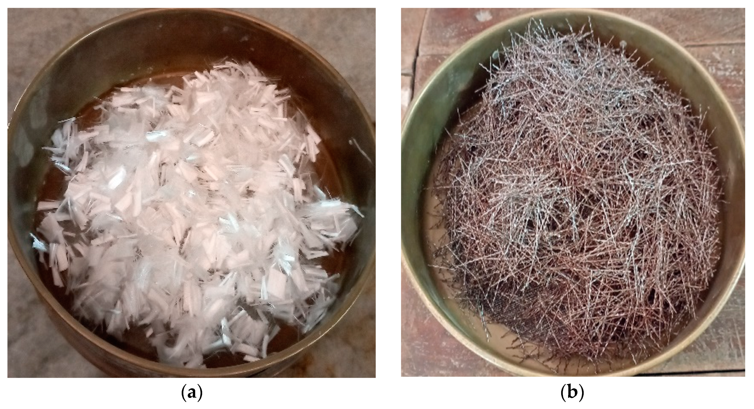
2.1.5. Polypropylene and Steel Fibres

This study used polypropylene fibre with an aspect ratio of 300 and crimped steel fibres with an aspect ratio of 66 in a hybrid form. Figure 1 shows the image of the fibres used in this study. The properties of the polypropylene and steel fibres are given in Table 4.

2.2. Mixture Proportions for TGPC

In this present study, the mixture proportions for the TGPC were calculated by trial and error method in accordance with the guidelines proposed by Rangan [30], as there is no standard procedure for GPC mix design yet. The detailed studies on the mix design of TGPC by the authors are published elsewhere [12,31]. The TGPC with a volume fraction of 60% fly ash, 25% GGBS, and 15% metakaolin was picked in this work as a ternary blend. The alkaline activator to binder ratio was constant at 0.3 with a 14 M sodium hydroxide solution. The sodium silicate to sodium hydroxide ratio was fixed at 2.5 for all the mix proportions. For better workability of TGPC, additional water to binder ratio of 0.2 with a superplasticier content of 1.5% of the weight of the source material was considered. Eight HTGPC mix proportions with different volume fractions of steel fibres (0.5% and 1%) and polypropylene fibres (0.1%, 0.15%, 0.2% and 0.25%) were considered and compared with TGPC (without fibres). The mixture proportions of all the specimens are tabulated in Table 5.

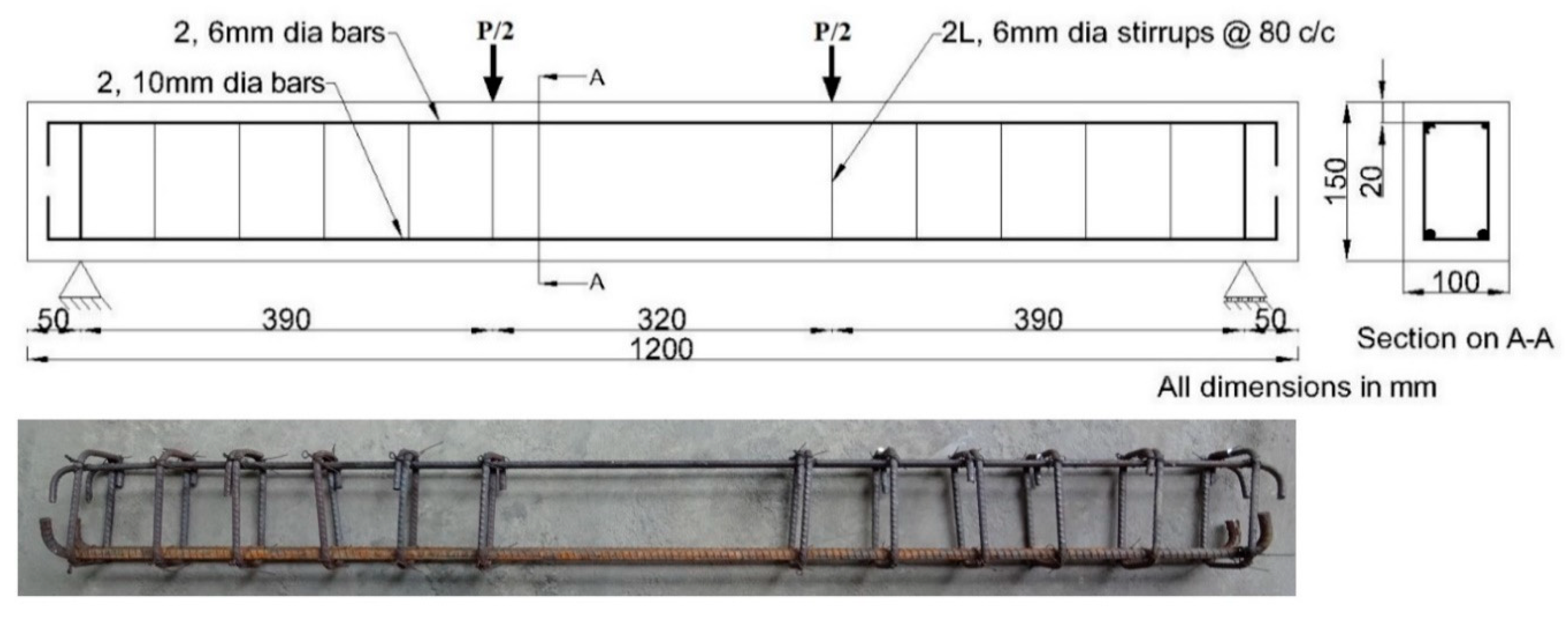
2.3. Details of the Specimen

Nine beams of length 1200 mm, depth of 150 mm, and width of 100 mm were cast to study the effect of hybrid fibres on the flexural behaviour of TGPC. For each mixture proportion, three beams were tested, and the average test result was considered for this investigation. The measurements and reinforcement details of the beam are shown in Figure 2. Two high yield strength deformed (HYSD) bars of 10 mm diameter were used as a tension reinforcement, and two number of 6 mm diameter HYSD bars were used as a compression reinforcement, as shown in Figure 2. Two leg stirrups with 6 mm diameter bars were provided at 80 mm c/c spacing as shear reinforcement to ensure the flexural failure of the beam. The mechanical properties of the bars are provided in Table 6.

2.4. Casting and Curing Procedure

At first, the dry components, which include the source materials, fine aggregate and coarse aggregate, were mixed thoroughly in a horizontal tilting drum concrete mixer. Sodium silicate and sodium hydroxide (14 M) solution were mixed before 24 h of the TGPC mixture as an alkaline activator [12,32]. The alkaline activator mixed with water and superplasticiser was then added to the dry mix. The fibres were added according to the mixture designation. It is advisable to add the polypropylene fibres before adding the liquid components to achieve a uniform distribution of fibres. The steel fibres were finally added prior to 5–10 rotations of the mixer to control the distortion of fibres. Then, the mixture was filled and compacted with a needle vibrator in a steel mould. Three specimens were cast for each mix proportion. The specimens were then wrapped using a plastic film to prevent moisture loss at the time of steam curing. After 24 h, The beam specimens were cured inside the steam curing chamber [3] at 60 °C for an extra 24 h. The samples were then removed from the curing chamber, unmoulded, and stored in normal room condition till testing.

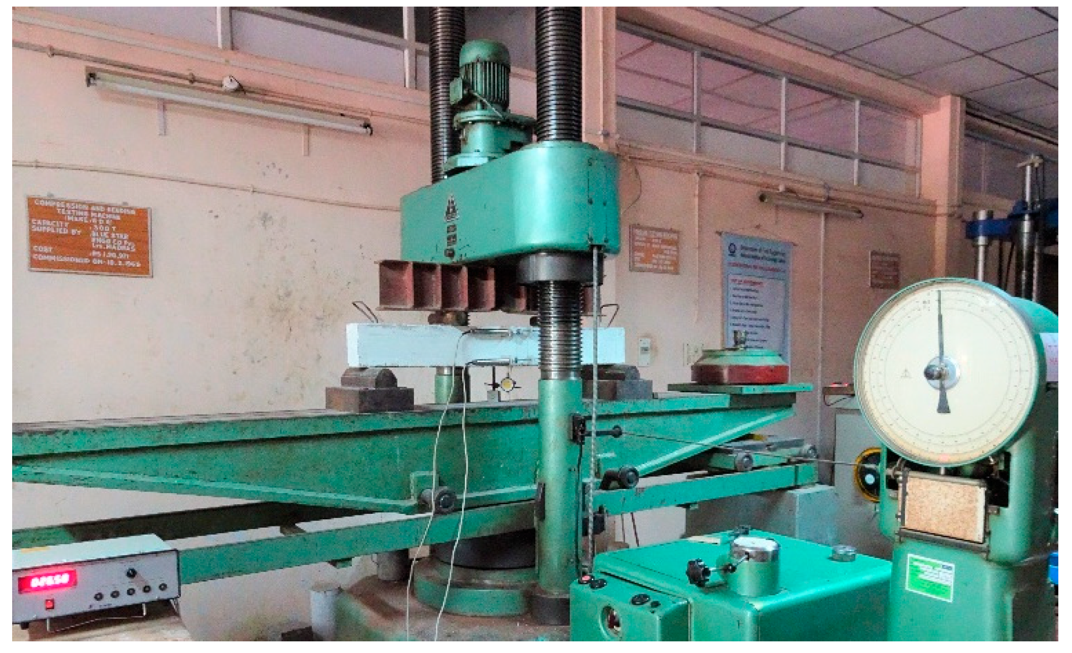
2.5. Testing Procedure

All the beams were whitewashed before testing to view the crack patterns clearly. The beams were tested under four-point loading in compression and bending testing machine of capacity 3000 kN, as shown in Figure 3. The test was performed in load-controlled loading conditions, and the rate of loading was kept constant at 4 kN/min till the beam failed. Due to the inherent limitations of the testing machine, a complete cure beyond the peak load could not be obtained. Hence, full attention was given to recording the deformation of up to 80% of the post-peak load. The results obtained up to 80% of the peak load could be considered accurate in view of the above. For calculation purposes, only these recorded values, up to 80% of the post-peak load, were utilised. The concrete surface strains at the midspan were noted with the help of two linear variable differential transformers (LVDT) located at 20 mm below the top and 20 mm above the bottom. A dial gauge with a least count of 10 microns was positioned at the bottom centre of the beam to monitor the deflection at every stage of loading. The crack pattern at each stage of loading was viewed using a crack detection microscope having the least count of 20 microns. The test readings were noted for every 2 kN increase in applied load.

3. Results and Discussions

Table 7 presents the flexural test results of the beam specimens. The tabulated test results are the mean value of three specimens with the same volume fraction of hybrid fibres.

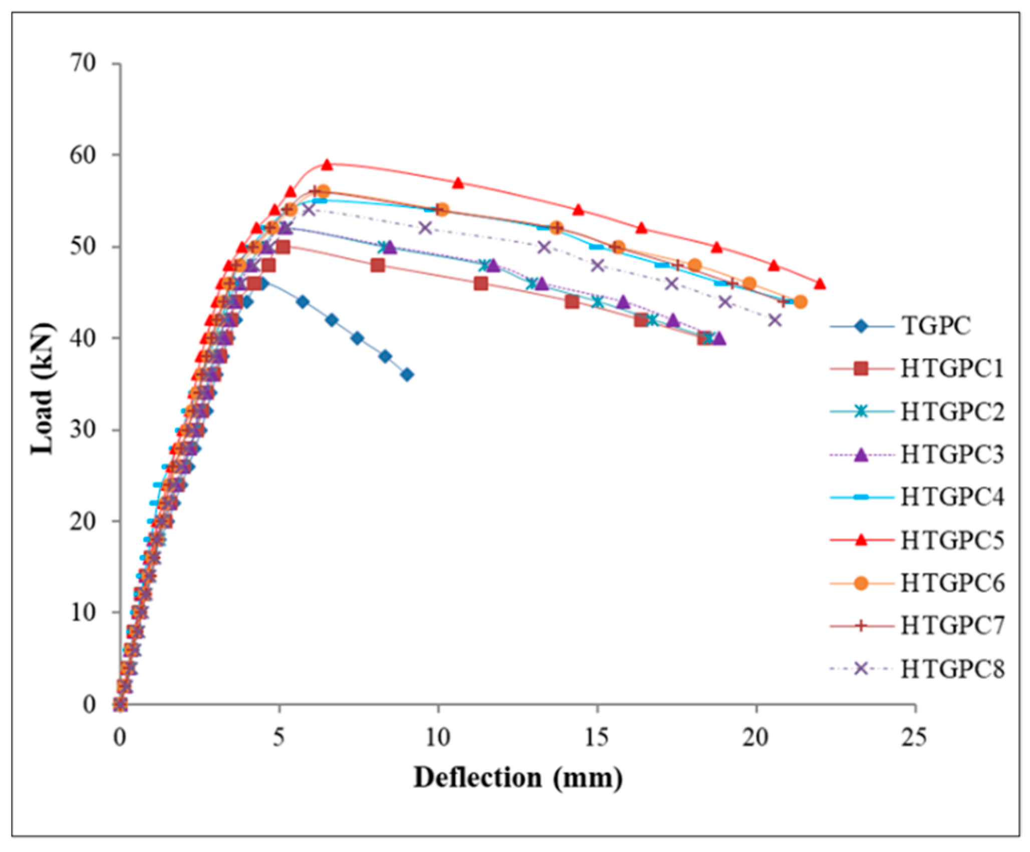
3.1. Load-Deflection Response

Load versus mid-span deflection curves for all the beams were plotted, and the observation is given in Figure 4. Each curve in Figure 4 is obtained from the mean test result of 3 specimens considered for each mix proportion. The statistical significance threshold considered for the present study was 5%. It may be noted from Figure that all the curves are linear up to the first crack load. The additional applied load developed multiple cracks, and the curve deviated from linearity to a nonlinear region. After the multiple cracking stages, the slope of the curve decreases for the specimen reinforced with hybrid fibre [33]. A sudden drop in the load was observed beyond the peak load for the specimens without fibres and a more or less flat curve for the specimens with hybrid fibres [34]. The specimens with higher fibre content showed less deformation for the same magnitude of load due to the higher stiffness of steel fibres. The maximum deflection is obtained from HTGPC specimens with 1% steel fibres. This may be due to the fact that as the steel fibre content increases, the ability to bridge wide cracks at high strain levels increases. The specimens with hybrid fibres produced an increase in peak load and a more ductile softening behaviour. The specimens with 1% of steel and 0.1% of polypropylene fibre exhibited better performance than the other specimens.

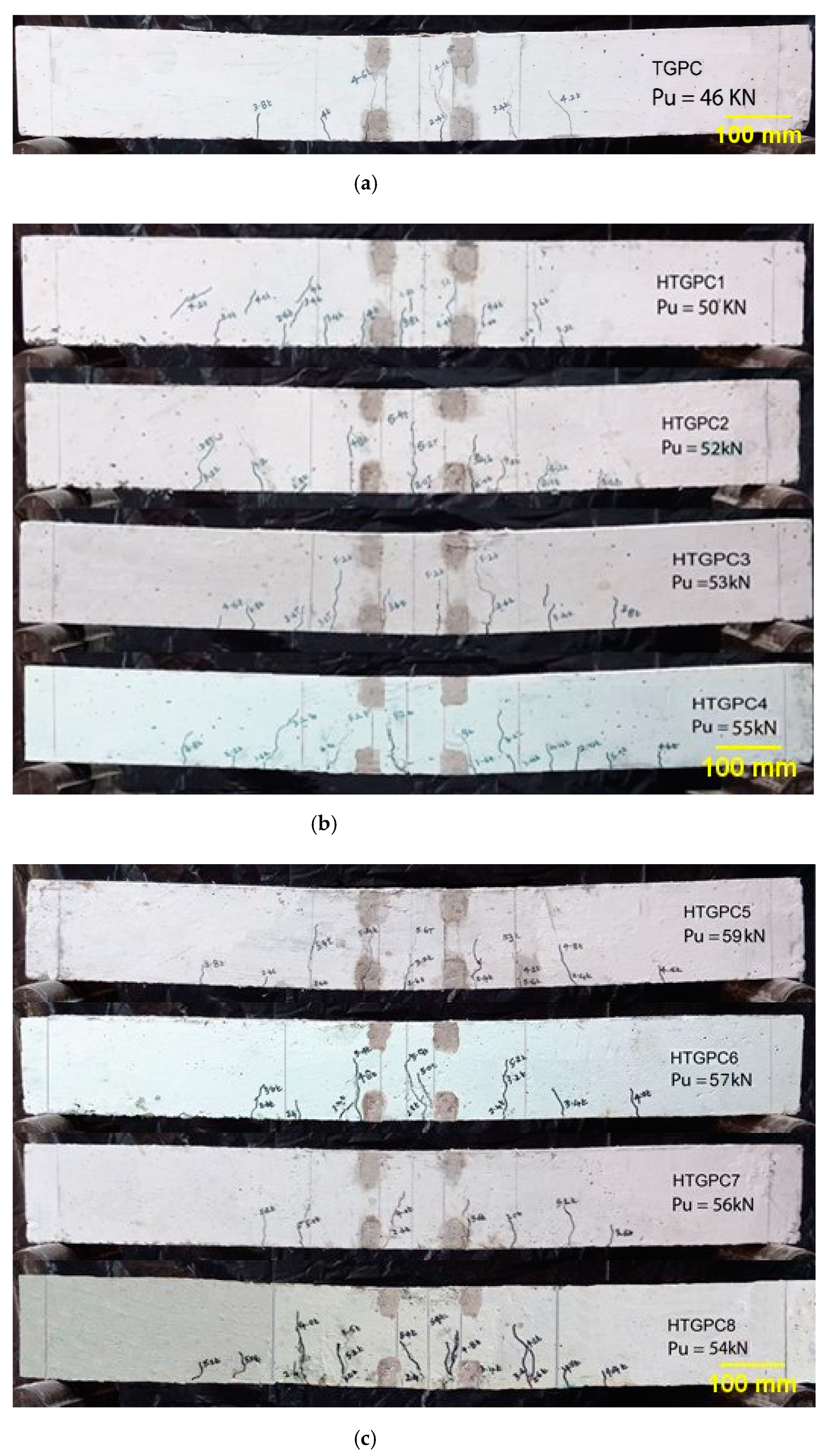
3.2. First Crack and Ultimate Crack Load

The values of the test results obtained from the flexural test on the beams are given in Table 7. It can be observed from Table that the first crack load increased with the increase in volume fraction of fibres. This may be associated with the improvement in the tensile strain carrying capacity of HTGPC in the region of fibres [35]. Ultimate load also gradually increased as the fibre content increased. The increase in the ultimate load ranges from 8% to 28% for the hybrid fibres. The first crack load increased by about 75% for the HTGPC with a volume fraction of 1% steel fibre and 0.1% polypropylene fibre. This may be due to polypropylene fibres’ ability to arrest the microcracks, which delayed the formation of macrocracks [36]. During the development of microcracks in the matrix, the polypropylene fibres in the neighbourhood of such microcracks will try to control these cracks and avoid further development. The steel fibres arrest as the cracks develop, and the bridging effect of fibres minimise the cracks from widening. Additionally, due to the interception of steel fibres, the cracks have to take a longer path, which results in the need for further energy; this consecutively results in the increase in ultimate load [37]. However, it has been noticed as the volume fraction of polypropylene fibres increases; the strength is reduced due to the balling effect of fibre, which results in reduced workability of concrete.

3.3. Energy Absorption Capacity and Ductility

The energy absorption capacity of the specimens can be expressed from the area under the load-deflection plots. It may to observed that the energy absorption capacity ranges from 0.155 kNm to 0.324 kNm for the specimens. In addition, the HTGPC beams with 1% steel and 0.15% polypropylene fibres exhibited the highest energy absorption capacity compared with other specimens considered in this investigation. Hence, it may be analysed that the hybrid fibre combination of more than 1% steel and 0.15% polypropylene cannot enhance the energy absorption capacity. This may be due to the poor binding force of the fibres with concrete resulting from the balling effect of the fibres [11]. The increase in the energy absorption capacity may be associated with the higher load-carrying capacity of the beam that can withstand larger deformation due to the effect of hybrid fibres [33].
The ductility factor is defined as the ratio of the deflection corresponding to 80% of the ultimate load (Pu) in the post-peak load region (δu) to deflection at first yield (δy) [38]. This takes into account the softening part of the load-deflection curve. Softening ductility consideration is important in seismic design and in cases where large deformations are expected [39]. The method followed to calculate the deflection at first yield load was explained elsewhere [40]. The results for all the tested specimens are given in Table 7. It can be seen that the addition of hybrid fibres resulted in a considerable increase in ductility. The improved ductility signifies the improved inelastic energy absorption due to the incorporation of fibres in the hybrid form [41]. The increase in the values of ductility factor was about 2.64 times for the HTGPC beams with 1% steel and 0.1% polypropylene fibre than the TGPC specimens.

3.4. Cracking Behaviour

As expected, flexure cracks were initiated in the pure bending zone, but due to the constant moment applied in the middle span of the beam, the sequence of crack formation was random within this region. As the load increased, new cracks were developed and merged with the existing cracks along the span [42]. Near the peak load, the beam deflected significantly, thus indicating that tensile steel must have yielded at failure. The cracks at the mid-span of the beams opened widely when the beam reached the ultimate load and near failure. Figure 5 shows the crack patterns of the tested beams. In TGPC specimens, compression concrete spalling occurred, whereas the HTGPC beams were intact, and the hybrid fibres prevented the spalling of concrete [43]. In HTGPC beams, crack initiation and propagation were delayed, and a large number of finer cracks developed in the flexure span and started widening when the load was increased. At higher loads, the crack pattern was not uniform. This may be due to the interception of fibres. The bridging action of the steel and polypropylene fibres was visible in the tensile part of the members. This justifies the control of cracks at macro and micro levels, respectively [36]. The addition of hybrid fibres improved the first crack load, ultimate load and deflection at ultimate load.

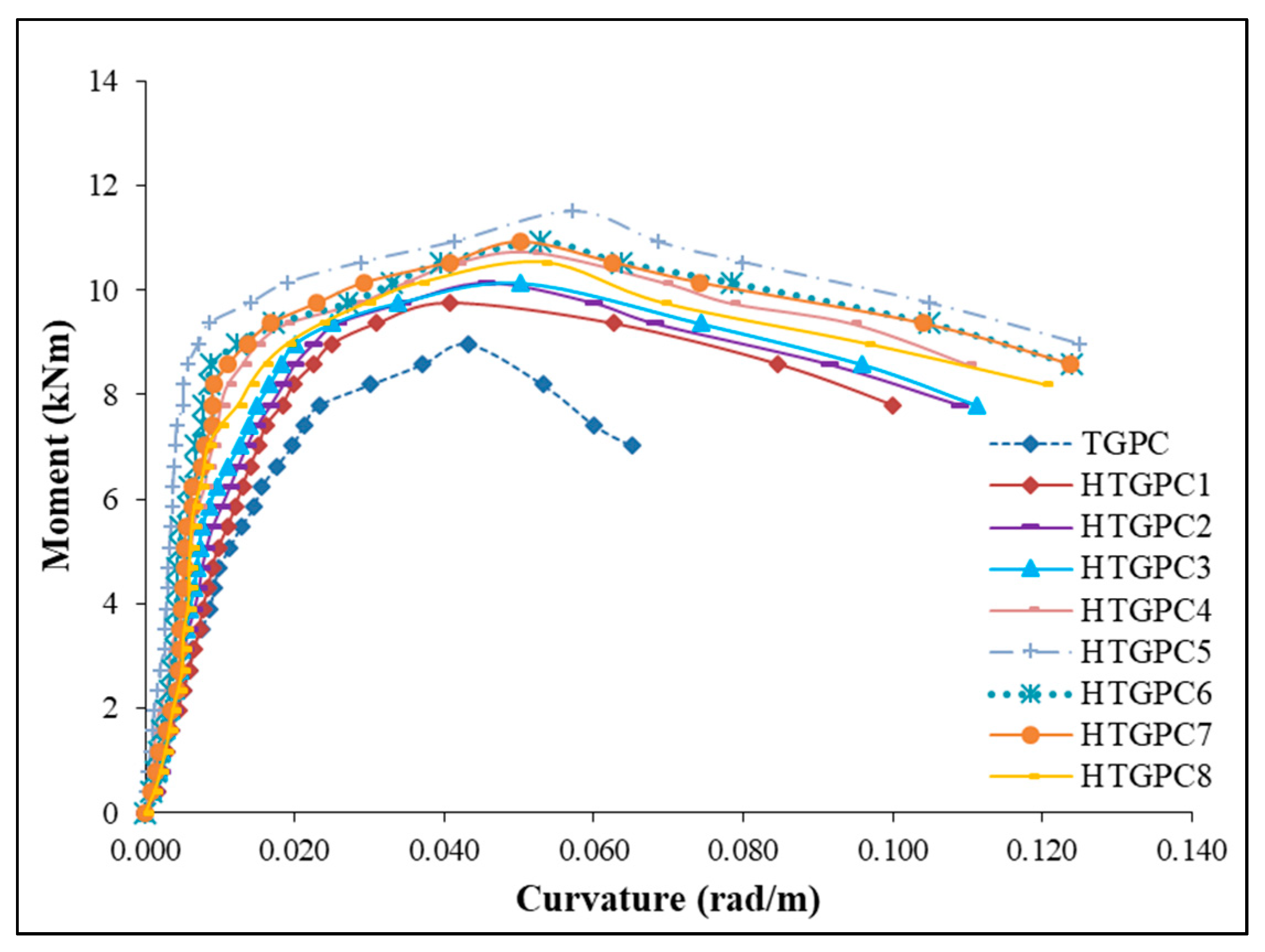
3.5. Moment-Curvature Relationship

An attempt was made to plot the moment-curvature relationship for all the specimens. The curvature was computed from the strains on the concrete surface observed from the deformations measured using the two LVDTs placed at the top and bottom level of the beam specimen, as shown in Figure 6. The strain in compression ( ε c ) and strain in tension ( ε s ) were calculated using the following equations,
ε c = Δ c G L
ε s = Δ s G L
where,
  • Δ c is the deformation obtained from the top LVDT
  • Δ s is the deformation obtained from the bottom LVDT
  • GL is the gauge length of LVDTs
Figure 6. Comparison of moment-curvature plots.
Sustainability 14 05954 g006
The symbol “ϕ” denotes the curvature of the reinforced concrete member, and it is obtained from Equation given by,
ϕ = ε c + ε s d l
where, d l is the distance between the top and bottom LVDTs.
The moment was calculated using the equation (relevant to the particular loading configuration),
M = 0.195P
The moment-curvature plots for all the specimens obtained from the experimental results are shown in Figure 6. Figure shows that all the curves are linear up to the first crack moment, beyond which they exhibit nonlinear characteristics. This may be due to the following reasons. The material behaves similar to a homogeneous composite until the formation of the first cracking. After that, multiple micro and macro cracks develop, leading to an increase in deflection or curvature. Fibres bridges these cracks, so the cracks may have to deviate from their propagation path. The above mechanism of cracking results in the softening of the material, and this will continue till the yielding of steel [36]. The curve becomes more or less flat after the yielding of steel bars [44].

3.6. Prediction of Flexural Strength of HTGPC

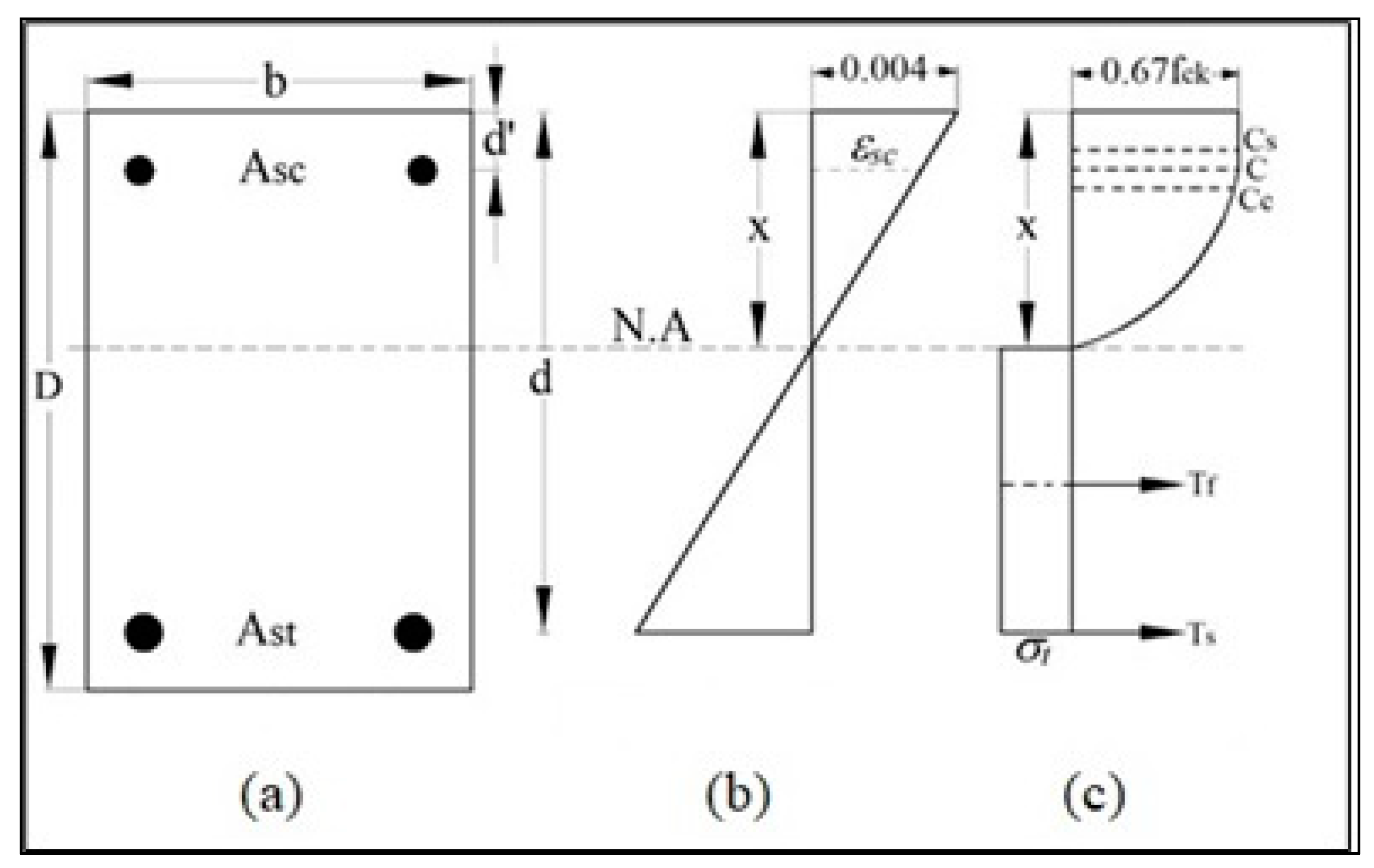
3.6.1. Modification of Stress Block

As per IS 456:2000 (reaffirmed 2021) [45], the maximum strain under flexure is considered 0.0035, which is slightly conservative for HTGPC. The experimental investigation observed that maximum strain increases up to 0.005 and above for HTGPC specimens with different volume fractions of steel and polypropylene fibres. Therefore, to modify the stress block parameters, the maximum strain in compression is limited to 0.004 [46]. The following assumptions were also made:
  • The strain diagram is linear.
  • A parabolic cum rectangular stress block in the compression zone of the section.
  • A rectangular stress distribution represents the contribution of fibres in the tension zone.
  • The compressive strength in concrete shall be assumed to be 0.67 times the characteristic strength.
With the above assumptions, the strain and stress diagrams across the beam’s cross-section are shown in Figure 7. Figure 7a represents the cross-section of the beam, and the strain distribution diagram with modified strain in the compression is shown in Figure 7b. Figure 7c depicts the effect of fibres that were considered only below the neutral axis [47,48]. Referring to Figure, the total compressive force (C) and tensile force (T) are given by,
C = C c + C s
T = T s + T f
where,
  • Cc = compressive force in concrete
  • Cs = compressive force in compression steel
  • Ts = tensile force in tension steel
  • Tf = tensile force in concrete composite below neutral axis due to the tensile strength of fibres.
Figure 7. Modified stress-strain distribution across a cross-section: (a) cross section of the beam; (b) strain distribution; (c) stress distribution.
Sustainability 14 05954 g007
The parameters in Figure 7 were determined using the following method. In the characteristic stress-strain curve for concrete in flexural compression, assuming a parabola in the initial region up to a strain of 0.002, the depth of the rectangular portion will be 0.5x and below which it varies parabolically over a depth of 0.5x to zero at the neutral axis, as shown in Figure 7.

3.6.2. Determination of Total Compressive Force (C)

For the rectangular section of width b,
C c = 0.67 f c k b ( x 2 + ( 2 3   x 2 ) ) = 0.56 f c k b x
The line of action of Cc is determined by the centroid of the stress block, located at a distance of k2x from the extreme compression fibre. Considering the moments of compressive forces about the extreme compressive fibre, the total moment due to Cc will be equal to the moments due to C1 and C2.
C c ( k 2 x ) = C 1 ( 1 4 )   x + C 2 ( x 5 8   x 2 )
( 0.56 f c k b x ) ( k 2 x ) = 0.67 f c k b x ( ( 1 2 1 4 x ) + ( 2 3 1 2 ) ( x 5 8   x 2 ) )
By solving,
k 2 = 0.425
Cs can be calculated by finding the strain in compression steel (εsc) using strain compatibility.
ε s c = 0.004   ( 1 d x )
Cs = Asc εsc Esc
where,
  • Asc = area of steel in compression
  • Esc = modulus of elasticity of compression steel
Hence, the total compressive force (C) is given by,
C = A sc   ε sc   E sc + 0.56 f c k b x
Point of action at C,
Let yc be the distance from the extreme compression fibre to the point of action of C. Taking moment about the extreme top plane,
C y c = C s d + C c k 2 x
C y c = A s c   ( 0.004 ( 1 d x ) ) E s c d + 0.56 f c k b x ( 0.425 x )
y c = A s c ( 0.004   ( 1 d x ) ) E s c d + 0.56   f c k b   x   ( 0.425 x ) A s c ( d d x ) 0.004 E s c + 0.56 f c k b   x

3.6.3. Determination of Total Tensile Force (T)

T s = A s t   f y
The tensile strength of fibre-reinforced composite is given by the law of mixtures, as the sum of matrix strength and fibre strength [49] as follows:
σ t = σ m V m + σ f V f
where,
  • σ t = strength of fibre-reinforced composite
  • σ f = strength of fibres
  • σ m = strength of the matrix
  • Vf = volume of fibres
  • Vm = volume of matrix = 1  Vf
At the ultimate state, the strength contribution of the concrete matrix may be safely neglected after the cracking of the composite. Thus, the ultimate strength of the composite is given by,
σ t = σ f V f
The tensile strength of the fibres depends on the length, bond efficiency factor, orientation and interfacial bond stress. The tensile strength of the fibre is given by [50],
σ f = η   η 1   η b   2 τ l f d f  
where η is the orientation factor equal to 0.41 for the three-dimensional random orientation of fibres [50], η 1 is the length efficiency factor, which accounts for the varying fibre stress at the end portions of the fibres and is equal to 0.5 [46], η b is the bond efficiency factor, and its value varies from 1 to 1.2 depending upon fibre characteristics; 1.2 for crimped steel fibres and 1.0 for smooth straight fibres [50]. τ is the fibre-matrix interfacial bond stress, taken as 5.12 MPa for crimped steel fibres and 4.15 MPa for plain fibres [51].
Hence, the ultimate tensile strength of hybrid fibre-reinforced composite can be taken as,
σ t =   σ fs V s +   σ fp V p
where σ f s   and σ f p   are the tensile strengths of steel and polypropylene fibres, respectively.
Therefore, the tensile force in the concrete composite below the neutral axis due to the tensile strength of fibres is given by,
Tf = b(D x) σt

3.6.4. Depth of Neutral Axis

Equating the total compressive force (C) and tensile force (T),
C c + C s = T s + T f
Asc εsc Esc + 0.56 fck b x = Ast fy + σt b (D x)
By solving Equation (24), the depth of the neutral axis ‘x’ can be determined.

3.6.5. Ultimate Flexural Strength

Ultimate flexural strength can be calculated as,
M u ( p r e ) = T s   ( d y c ) + T f   { ( D x 2 ) + ( x y c ) }
M u ( p r e ) = A s t f y   ( d y c ) + b ( D x ) σ t   { ( D x 2 ) + ( x y c ) }
The obtained results are tabulated in Table 8. It may be noted that the proposed method predicts flexural strength and compare satisfactorily with the experimental test results (Mu(exp)).

4. Conclusions

This study presented the experimental investigation of the flexural behaviour of HTGPC beams. Based on the test results, the following conclusions can be drawn:
  • The experimental results revealed that the addition of fibres in TGPC enhances the post-peak performance, showing a softening behaviour of the material. The fibres in hybrid form limit the sudden failure and change to a soft form.
  • The fibres in hybrid form impact the load at different levels and improve the deflection corresponding to the load.
  • The addition of hybrid fibres improved the specimens’ first crack load and ultimate load. The first crack load was found to increase significantly by 75%, and the ultimate load was found to increase by 28% compared with the specimens without fibres.
  • The displacement ductility factor and the energy absorption capacity were increased by 2.64 times and 2.09 times, respectively, for the HTGPC specimen with 1% steel fibres and 0.1% polypropylene fibres compared with the specimens without fibres.
  • IS 456:2000 recommend a maximum strain of 0.0035 for the specimens under flexure. However, this value is found to be conservative based on the test results of HTGPC specimens, and a maximum strain of 0.004 could be considered in the stress block for HTGPC.
  • The method proposed for estimating the flexural strength of HTGPC was compared satisfactorily with the test results. The effect of the addition of hybrid fibres in the tension zone is considered in this model.

Author Contributions

Conceptualisation, V.S.K., N.G. and P.V.I.; methodology, V.S.K., N.G. and P.V.I.; software, V.S.K., N.G. and P.V.I.; validation, V.S.K., N.G. and P.V.I.; formal analysis, V.S.K., N.G. and P.V.I.; investigation, V.S.K., N.G. and P.V.I.; resources, V.S.K., N.G. and P.V.I.; writing—original draft preparation, V.S.K., N.G., P.V.I., G.M. and N.I.V.; writing—review and editing, V.S.K., N.G., P.V.I., G.M. and N.I.V.; visualisation, N.G. and P.V.I.; supervision, N.G. and P.V.I.; project administration, N.G. and P.V.I.; funding acquisition, G.M. and N.I.V. All authors have read and agreed to the published version of the manuscript.

Funding

The research is partially funded by the Ministry of Science and Higher Education of the Russian Federation as part of the World-class Research Center program: Advanced Digital Technologies (contract No. 075-15-2022-311 dated 20.04.2022).

Institutional Review Board Statement

Not applicable.

Informed Consent Statement

Not applicable.

Data Availability Statement

Not applicable.

Acknowledgments

The authors would like to acknowledge the National Institute of Technology Calicut, India, for extending the facilities to complete this project successfully.

Conflicts of Interest

The authors declare no conflict of interest.

References

  1. Jena, S.; Panigrahi, R.; Pooja, S. Mechanical and Durability Properties of Fly Ash Geopolymer Concrete with Silica Fume. J. Inst. Eng. Ser. A 2019, 100, 697–705. [Google Scholar] [CrossRef]
  2. Mclellan, B.C.; Williams, R.P.; Lay, J.; Van Riessen, A.; Corder, G.D. Costs and carbon emissions for geopolymer pastes in comparison to ordinary portland cement. J. Clean. Prod. 2011, 19, 1080–1090. [Google Scholar] [CrossRef] [Green Version]
  3. Sathish Kumar, V.; Ganesan, N.; Indira, P.V. Engineering Properties of Hybrid Fibre Reinforced Ternary Blend Geopolymer Concrete. J. Compos. Sci. 2021, 5, 203. [Google Scholar] [CrossRef]
  4. Nurruddin, M.F.; Haruna, S.; Mohammed, B.S.; Galal, I. Methods of curing geopolymer concrete: A review. Int. J. Adv. Appl. Sci. 2018, 5, 31–36. [Google Scholar] [CrossRef]
  5. Abdul Aleem, M.I.; Arumairaj, P.D. Geopolymer Concrete—A Review. Int. J. Eng. Sci. Emerg. Technol. 2016, 1, 118–122. [Google Scholar] [CrossRef]
  6. Alftah, R.O.A.; Elbaky, S.A.A.; Ghanem, G.; Sadek, D.M. Production of geo-polymer concrete from GGBS with different ratios of fly ash. Int. J. Adv. Res. Eng. Technol. 2020, 11, 1002–1010. [Google Scholar] [CrossRef]
  7. Mallikarjuna Rao, G.; Gunneswara Rao, T.D. Effect of fly ash and GGBS combination on mechanical and durability properties of GPC. Adv. Concr. Constr. 2017, 5, 313–330. [Google Scholar] [CrossRef]
  8. Nagalingam, G.; Chokkalingam, R.B. Strength studies on geopolymer concrete with GGBS and Fly ash. IOP Conf. Ser. Mater. Sci. Eng. 2020, 872, 012107. [Google Scholar] [CrossRef]
  9. Jawahar, J.G.; Mounika, G. Strength properties of fly ash and GGBS based geo polymer concrete. Asian J. Civ. Eng. 2016, 17, 127–135. [Google Scholar]
  10. Xie, J.; Wang, J.; Rao, R.; Wang, C.; Fang, C. Effects of combined usage of GGBS and fly ash on workability and mechanical properties of alkali activated geopolymer concrete with recycled aggregate. Compos. Part B Eng. 2019, 164, 179–190. [Google Scholar] [CrossRef]
  11. Sathish Kumar, V.; Ganesan, N.; Indira, P. V Shear Strength of Hybrid Fibre-Reinforced Ternary Blend Geopolymer Concrete Beams under Flexure. Materials 2021, 14, 6634. [Google Scholar] [CrossRef] [PubMed]
  12. Sathish Kumar, V.; Ganesan, N.; Indira, P.V. Effect of Molarity of Sodium Hydroxide and Curing Method on the Compressive Strength of Ternary Blend Geopolymer Concrete. IOP Conf. Ser. Earth Environ. Sci. 2017, 80, 012011. [Google Scholar] [CrossRef] [Green Version]
  13. Gharieb, M.; Mosleh, Y.A.; Rashad, A.M. Properties and corrosion behaviour of applicable binary and ternary geopolymer blends. Int. J. Sustain. Eng. 2021, 14, 1068–1080. [Google Scholar] [CrossRef]
  14. Holmes, N. Structural Properties of Concrete Materials Containing RoadCem. J. Constr. Eng. 2015, 2015, 795080. [Google Scholar] [CrossRef] [Green Version]
  15. Bandara, M.M.H.W.; Mampearachchi, W.K.; Anojan, T. Enhance the properties of concrete using pre-developed burnt clay chips as internally curing concrete aggregate. Case Stud. Constr. Mater. 2019, 11, e00284. [Google Scholar] [CrossRef]
  16. Kiran, T.; Anand, N.; Kumar, S.N.; Andrushia, D.; Arulraj, P. Influence of nano-cementitious materials on improving the corrosion resistance and microstructure characteristics of concrete. J. Adhes. Sci. Technol. 2021, 35, 1995–2022. [Google Scholar] [CrossRef]
  17. Wu, H.; Lin, X.; Zhou, A. A review of mechanical properties of fibre reinforced concrete at elevated temperatures. Cem. Concr. Res. 2020, 135, 106117. [Google Scholar] [CrossRef]
  18. Paul, S.C.; Van Zijl, G.P.A.G.; Savija, B. Effect of Fibers on Durability of Concrete: A Practical Review. Materials 2020, 13, 4562. [Google Scholar] [CrossRef]
  19. Alex, X.I.; Arunachalam, K. Flexural behavior of fiber reinforced lightweight concrete. Rev. Constr. 2019, 18, 536–544. [Google Scholar] [CrossRef]
  20. Concrete, F.; Toši, N.; Aidarov, S.; Fuente, A. De Systematic Review on the Creep of Fiber-Reinforced Concrete. Materials 2020, 13, 5098. [Google Scholar] [CrossRef]
  21. Sathish Kumar, V.; Indira, P.V.; Ganesan, N. Tension stiffening and cracking behaviour of hybrid fibre reinforced ternary blend geopolymer concrete. J. Struct. Eng. 2019, 46, 257–266. [Google Scholar]
  22. Sathish Kumar, V.; Ganesan, N.; Indira, P.V. Effect of Hybrid Fibres on the Durability Characteristics of Ternary Blend Geopolymer Concrete. J. Compos. Sci. 2021, 5, 279. [Google Scholar] [CrossRef]
  23. Meda, A.; Minelli, F.; Plizzari, G.A. Flexural behaviour of RC beams in fibre reinforced concrete. Compos. Part B 2012, 43, 2930–2937. [Google Scholar] [CrossRef]
  24. Fatih, I.; Ashour, A.F.; Körog, M.A. Flexural behavior of hybrid FRP/steel reinforced concrete beams. Compos. Struct. 2015, 129, 111–121. [Google Scholar] [CrossRef]
  25. Yoo, D.; Banthia, N.; Kang, S.; Yoon, Y. Effect of fiber orientation on the rate-dependent flexural behavior of ultra-high-performance fiber-reinforced concrete. Compos. Struct. 2016, 157, 62–70. [Google Scholar] [CrossRef]
  26. Teo, D.C.L.; Mannan, M.A.; Kurian, J.V. Flexural Behaviour of Reinforced Lightweight Concrete Beams Made with Oil Palm Shell (OPS). J. Adv. Concr. Technol. 2006, 4, 459–468. [Google Scholar] [CrossRef] [Green Version]
  27. IS 3812:2003; Pulvarized Fuel Ash—Specification. Bureau of Indian Standards: New Delhi, India, 2003.
  28. BS 6699:1992; Ground Granulated Blast Furnace Slag for Use with Portland Cement—Specification. British Standards Institution: London, UK, 1992.
  29. IS 383:1970; Specification for Coarse and Fine Aggregates from Natural Sources for Concrete. Bureau of Indian Standards: New Delhi, India, 2002; reaffirmed 2002.
  30. Lloyd, N.A.; Rangan, B.V. Geopolymer concrete with fly ash. In Proceedings of the Second International Conference on Sustainable Construction Materials and Technologies, Ancona, Italy, 28 June 2010; pp. 1493–1504. [Google Scholar]
  31. Ganesan, N.; Indira, P.V.; Sathish Kumar, V. Effect of Alkaline Activator to Binder Ratio on the Compressive Strength of Ternary Blend Geopolymer Concrete. ICI J. 2017, 17, 22–27. [Google Scholar]
  32. Nagalia, G.; Park, Y.; Ph, D.; Asce, M.; Abolmaali, A.; Ph, D.; Asce, M.; Aswath, P.; Ph, D. Compressive Strength and Microstructural Properties of Fly Ash—Based Geopolymer Concrete. J. Mater. Civ. Eng. 2016, 28, 1–11. [Google Scholar] [CrossRef]
  33. Raj, S.D.; Ramachandran, A. Performance of hybrid fibre reinforced geopolymer concrete beams. SN Appl. Sci. 2019, 1, 1725. [Google Scholar] [CrossRef] [Green Version]
  34. Varouqa, I.F. Flexural Behavior of Reinforced Concrete Beams with High Performance Fibers. Int. J. Eng. Manuf. 2021, 2, 31–39. [Google Scholar] [CrossRef]
  35. Ganesan, N.; Indira, P.V.; Sabeena, M.V. Behaviour of hybrid fibre reinforced concrete beam-column joints under reverse cyclic loads. Mater. Des. 2014, 54, 686–693. [Google Scholar] [CrossRef]
  36. Sivakumar, A.; Santhanam, M. Mechanical properties of high strength concrete reinforced with metallic and non-metallic fibres. Cem. Concr. Compos. 2007, 29, 603–608. [Google Scholar] [CrossRef]
  37. Ganesan, N.; Indira, P.V.; Sabeena, M.V. Effect of hybrid fibres on the shear and durability behaviour of high performance concrete. Int. J. Struct. Eng. 2015, 6, 44–55. [Google Scholar] [CrossRef]
  38. SungG-Woo Shin and Jaime Moreno, S.K.G. Flexural Ductility of Ultra-High-Strength Concrete Members. ACI Struct. J. 1989, 86, 394–400. [Google Scholar] [CrossRef]
  39. Pendyala, R.; Mendis, P.; Patnaikuni, I. Full-range behavior of high-strength concrete flexural members: Comparison of ductility parameters of high and normal-strength concrete members. ACI Struct. J. 1996, 93, 30–35. [Google Scholar]
  40. Ganesan, N.; Indira, P.V.; Ruby, A. Behaviour of steel fibre reinforced high performance concrete members under flexure. J. Inst. Eng. Civ. Eng. Div. 2007, 88, 20–23. [Google Scholar]
  41. Wang, H.; Belarbi, A. Ductility characteristics of fiber-reinforced-concrete beams reinforced with FRP rebars. Constr. Build. Mater. 2011, 25, 2391–2401. [Google Scholar] [CrossRef]
  42. Wei, J.; Li, J.; Wu, C.; Liu, Z.; Li, J. Hybrid fibre reinforced ultra-high performance concrete beams under static and impact loads. Eng. Struct. 2021, 245, 112921. [Google Scholar] [CrossRef]
  43. Chalioris, C.E.; Kosmidou, P.K.; Karayannis, C.G. Cyclic Response of Steel Fiber Reinforced Concrete Slender Beams: An Experimental Study. Materials 2019, 12, 1398. [Google Scholar] [CrossRef] [Green Version]
  44. Ganesan, N.; Bindurania, P.; Indira, P. V Flexural strengthening of RCC beams using FRPs and ferrocement—a comparative study. Adv. Concr. Constr. 2020, 10, 35–48. [Google Scholar] [CrossRef]
  45. IS 456:2000; Plain and Reinforced Concrete—Code of Practice. Bureau of Indian Standards: New Delhi, India, 2021; reaffirmed 2021.
  46. Lim, T.-Y.; Paramasivam, P.; Lee, S.-L. Behavior of Reinforced Steel-Fiber-Concrete Beams in Flexure. J. Struct. Eng. 1987, 113, 2439–2458. [Google Scholar] [CrossRef]
  47. Henager, C.H.; Doherty, T.J. Analysis of Reinforced Fibrous Concrete Beams. J. Struct. Div. 1976, 102, 177–188. [Google Scholar] [CrossRef]
  48. Khalil, W.I.; Tayfur, Y.R. Flexural strength of fibrous ultra high performance reinforced concrete beams. ARPN J. Eng. Appl. Sci. 2013, 8, 200–214. [Google Scholar]
  49. Markovic, I.; Walraven, J.C.; van Mier, J.G.M. Development of high performance hybrid fibre concrete. In International Workshop High Performance Fiber Reinforced Cement Composites; RILEM Publications SARL: Paris, France, 2003; pp. 277–300. [Google Scholar]
  50. Swamy, R.N.; AI-Ta’an, S.A. Deformation and Ultimate Strength in Flexure of Reinforced Concrete Beams Made with Steel Fiber Concrete. ACI J. Proc. 1981, 78, 395–405. [Google Scholar] [CrossRef]
  51. Khuntia, M.; Stojadinovic, B.; Goel, S.C. Shear Strength of Normal and High-Strength Fiber Reinforced Concrete Beams without Stirrups. ACI Struct. J. 1999, 96, 282–289. [Google Scholar] [CrossRef]
Figure 1. (a) Polypropylene fibres; (b) steel fibres.
Sustainability 14 05954 g001
Figure 2. Reinforcement details of the beam.
Sustainability 14 05954 g002
Figure 3. Test setup.
Sustainability 14 05954 g003
Figure 4. Comparison of load-deflection response.
Sustainability 14 05954 g004
Figure 5. Typical crack pattern of tested specimens: (a) TGPC; (b) Beams with 0.5% steel fibres; (c) beams with 1.0% steel fibres.
Sustainability 14 05954 g005
Table 1. Chemical components of fly ash.
Al2O3SiO2Fe2O3TiO2K2OCaO
27.75%55.36%9.74%3.54%2.55%1.07%
Table 2. Chemical components of GGBS.
CaOSiO2Al2O3MgOSFeOMnCl
37.04%32.49%20.86%7.82%0.98%0.68%0.11%0.012%
Table 3. Chemical components of metakaolin.
SiO2Al2O3Fe2O3Na2OK2OMgOTiO2CaO
56.64%42.38%0.42%0.11%0.04%0.2%0.1%0.1%
Table 4. Properties of fibres.
Type of FibreLengthDiameterTensile StrengthDensity
Polypropylene12 mm0.04 mm550–600 MPa950 kg/m3
Crimped steel30 mm0.45 mm800 MPa7950 kg/m3
Table 5. Mixture proportions of ternary blend geopolymer concrete (TGPC) and hybrid fibre-reinforced ternary blend geopolymer concrete (HTGPC).
Materials, kg/m3TGPCHTGPC1HTGPC2HTGPC3HTGPC4HTGPC5HTGPC6HTGPC7HTGPC8
Fly ash237.47237.47237.47237.47237.47237.47237.47237.47237.47
GGBS122.62122.62122.62122.62122.62122.62122.62122.62122.62
Metakaolin64.5264.5264.5264.5264.5264.5264.5264.5264.52
Fine aggregate554.40554.40554.40554.40554.40554.40554.40554.40554.40
Coarse
aggregate
1293.601293.601293.601293.601293.601293.601293.601293.601293.60
Na2SiO390.9990.9990.9990.9990.9990.9990.9990.9990.99
NaOH36.4036.4036.4036.4036.4036.4036.4036.4036.40
Water84.9284.9284.9284.9284.9284.9284.9284.9284.92
Superplasticiser6.376.376.376.376.376.376.376.376.37
Steel fibre-39.25 (0.5%)39.25 (0.5%)39.25 (0.5%)39.25 (0.5%)78.50
(1%)
78.50
(1%)
78.50
(1%)
78.50
(1%)
Polypropylene fibre-0.95
(0.1%)
1.425 (0.15%)1.90
(0.2%)
2.375 (0.25%)0.95
(0.1%)
1.425 (0.15%)1.90
(0.2%)
2.375 (0.25%)
Table 6. Properties of steel bars.
Nominal Diameter,
mm
Actual Diameter,
mm
Yield Strength,
MPa
Ultimate Strength,
MPa
Modulus of Elasticity,
GPa
109.94532580235
66.10525575230
Table 7. Test results.
Beam IDFirst Crack Load,
kN
Ultimate Load, Pu,
kN
Deflection at Pu,
mm
Energy
Absorption
Capacity, kNm
Deflection at 0.8 Pu, mmDeflection
at Yield Load, mm
Ductility
Factor
TGPC16464.480.1558.602.922.94
HTGPC118505.100.22218.353.135.87
HTGPC219525.20.25718.172.946.17
HTGPC320535.250.26118.553.076.04
HTGPC425556.260.27521.063.076.86
HTGPC528596.50.32421.422.767.76
HTGPC626576.370.30120.422.996.83
HTGPC725566.120.29719.962.936.81
HTGPC821545.90.29119.892.926.81
Table 8. Comparison of experimental and predicted flexural strength.
Beam IDMu(exp), kNmMu(pre), kNmMu(exp)/Mu(pre)
TGPC8.977.711.16
HTGPC19.758.791.11
HTGPC210.149.001.13
HTGPC310.149.211.10
HTGPC410.729.411.14
HTGPC511.519.471.21
HTGPC611.169.631.15
HTGPC710.929.841.11
HTGPC810.5310.041.05
Average1.13
Standard deviation0.05
Coefficient of variation (%)4.12
Publisher’s Note: MDPI stays neutral with regard to jurisdictional claims in published maps and institutional affiliations.

