Article

Relationship between the Vibration Acceleration and Stability of a Continuous Girder Bridge during Horizontal Rotation

Key Laboratory of Earthquake Engineering and Structural Retrofit of Beijing, Department of Civil Engineering, Beijing University of Technology, No.100 Ping Leyuan, Chaoyang District, Beijing 100124, China
*
Author to whom correspondence should be addressed.
Sustainability 2022, 14(10), 5853; https://doi.org/10.3390/su14105853
Submission received: 26 March 2022 / Revised: 27 April 2022 / Accepted: 5 May 2022 / Published: 12 May 2022

Abstract

:
To ensure the safety of bridges during horizontal rotation, we propose a method through which it is possible to evaluate the stability of structures in real time by measuring the vibration acceleration of the rotating structure. First, the vibration characteristics collected during the horizontal rotation of a typical high-speed railway bridge were compared with the results of a finite element analysis. Second, the analytic formula to calculate the ratio of vibration acceleration and the pier-bottom-section bending moment for the rotating structure was deduced by considering the beam and pier as an infinite-degree-of-freedom rod. Then, the results of the analytical formula were compared with those of the finite element calculation. Overall, the results showed that the bending moment of the pier bottom (which was related to the stability of the rotating bridge) was affected only by the two asymmetrical vibration modes. The analytic formula built by considering the beam and pier as an infinite degree-of-freedom rod with equal cross-section effectively described the relationship between the vibration acceleration and pier-bottom-bending moment. Finally, the vibration of the rotating bridge was simplified to the superposition of the first two asymmetric vibration modes in the facade. Based on our findings, we were able to provide a formula and some check tables to calculate the permissible value of vibration acceleration for typical high-speed railway bridges.

1. Introduction

With the reconstruction and upgrading of the traffic infrastructure, the demand for overpass bridges is steadily increasing. The horizontal rotation construction method has the advantages of site adaptability, fast construction, safety, reliability, and minimal disturbance to underpass traffic [1,2,3,4,5]; therefore, it is the preferred design and construction scheme for overpass-crossing railways (especially high-speed railways) [5]. The main structural systems of rotation construction bridges are a continuous bridge, a T-rigid frame bridge, and a cable-stayed bridge. Continuous or T-rigid frame bridges are best suited for spans <150 m, while cable-stayed bridges are ideal for spans >200 m. In the last ten years, the number of bridges built by the rotation construction method have linearly grown, while the swivel weight has exponentially grown. About 50–80 overpass bridges are built by the rotation construction method in China every year; the span of the swivel bridge is approaching 400 m and the maximum swivel tonnage is about to exceed 50,000 tons. Notably, the rotating structure is in a state of transient equilibrium, in which a single point is supported by a spherical hinge. Therefore, the structure will inevitably vibrate during the horizontal rotation caused by uncertain factors (e.g., environmental wind, ground vibration caused by vehicles, and slideway geometric imperfections) [6,7,8,9]. This vibration affects the safety of the structure and even causes its collapse if the exciting frequency nears the natural frequency of the rotating structure [10,11,12,13].
To ensure construction safety during horizontal rotation, it is necessary to monitor the stability of the rotating structure in real-time. The monitoring of the construction process, which involves checking the cross-section strain, the beam alignment, and performing unbalance weighting tests, is rather mature. However, there is still no relatively mature and recognized scheme for the safety monitoring of the rotation process. There are suggestions for monitoring the strain response of the key beam section, the monitoring of rotation speed, as well as the inclination angle of the structure during the rotation. However, these variables cannot directly and quickly reflect the overall stability of the rotating structure.
The monitoring and the evaluation technology of rotating structures’ stability need further development to ensure the safety of all bridge projects. Structure vibration monitoring has many special advantages; for example, the measure result is not sensitive to the material discreteness of the sensors’ local position, and sensors are easy to install and recycle [14,15,16,17,18]. The results obtained from the study of bridge vibration have been used in bridge health monitoring and for the control of construction-stage vibration in cable bridges [19,20,21,22,23]. The vibration response of the rotating structure should be tested when monitoring the horizontal rotation bridge projects during construction [24,25]. However, the relationship between the stability and vibration of the rotating structure has not been studied in detail yet, and it is difficult to use the vibration test results to quantitatively evaluate the risk of overturning the rotating structure. Such results can only be used, in combination with subjective experience, to qualitatively estimate the safety of the rotating structure. This will result in potential safety hazards. Therefore, determining the relationship between the stability and the vibration response of the rotating structure is necessary to monitor its safety.
The overturning of the rotating structure will occur when the overturning moment caused by the vibration will be equal to the stabilization moment provided by the rotating structure. This stabilization moment can be easily calculated. The key research point is hence to establish the relationship between the overturning moment and the vibration response of the rotating structure. In this paper, the vibration acceleration of the rotating structure was used as a monitoring variable to calculate the overturning moment.
First, the actual rotating structure’s vibration data collected for a typical high-speed railway bridge were compared with the structural dynamic characteristics calculated by the finite element method (FEM) to determine the general vibration rule of the rotating structure. Then, an analytic formula for calculating the pier-bottom bending moment of the rotating structure through the vibration acceleration of the beam end or of the pier top was deduced, which can be used to understand the vibration characteristics of the structure in the rotation process and analyze the internal causes of overturning. Then, the results of the analytical formula are compared with the finite element results to verify the correctness of the analytical formula. Finally, we obtained a simplified formula and provided reference tables to calculate the permissible value of vibration acceleration for typical high-speed railway bridges.

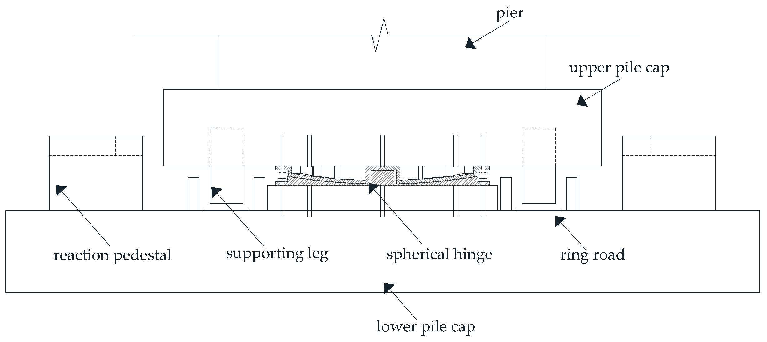
2. Main Construction Process of Horizontal Rotation Bridges

At present, the horizontal rotation construction method is mainly used for the building of continuous or T-rigid frame bridges. As shown in Figure 1, the special construction process of the horizontal rotation construction method includes rotating system construction, unbalanced weighting and balance counterweight before rotation, trial rotation, and formal rotation and monitoring.
As shown in Figure 2, the rotating system is composed of a down turntable, a spherical hinge, an up turntable, supporting legs, a ring road, and a rotating traction system. The design and construction quality of the rotating system is very important to ensure the success of rotation construction.
Although the rotating structure is usually designed as a symmetrical structure, errors are inevitable during the construction process. In order to ensure a successful construction of the rotating structure, the eccentricity of the rotating structure and the static friction coefficient of the spherical hinge need to be measured by unbalanced weighing after the construction of the rotating structure is completed. The eccentric effect of the rotating structure can be eliminated by balance counterweight. When the structure is formally rotated, the steel strand embedded in the up turntable is stretched by the jack placed at the reaction pedestal; a symmetrical force couple is exerted on the rotating structure, so that it rotates horizontally (Figure 3). In order to ensure the stability and safety of the rotating process, the vibration response of the rotating structure should be monitored in real time.

3. Vibration Characteristics Analysis of the Rotating Structure

In this study, the vibration characteristics of the rotating structure of the Shang-Yuan Bridge were tested during its horizontal rotation. This bridge belongs to the Datong-Xi’an high-speed railway, across the Shuo-Huang railway. The design speed of the Datong-Xi’an high-speed railway is 350 km/h, and its superstructure consists of a 60 m + 100 m + 60 m continuous, prestressed concrete box girder. The rotating structure pier is a circular end type hollow pier, pier height is 20 m, pier body outside according to 30:1 slope, pier body inside according to 80:1 slope, pier top section height is 4 m, width is 9 m, section moment of inertia is 39.233 m4; the main beam is box section, the cantilever end section height of the main beam is 4.604 m, the roof thickness is 0.354 m, the web thickness is 0.6 m, the bottom plate thickness is 0.4 m, the moment of inertia of the section is 37.95 m4, the root section height of the main beam is 7.204 m, the roof thickness is 0.554 m, the web thickness is 1 m, the bottom plate thickness is 1.2 m, the moment of inertia of the section is 174.44 m4; moreover, the size of upper turntable is 16.4 m × 10.8 m × 3.7 m, the diameter of upper spherical hinge 4.1 m, the diameter of the bottom spherical hinge 3.8 m, and the centerline diameter of the slide way 4.5 m.

3.1. Vibration Modal Analysis

The vibration mode of the rotating structure of the Shang-Yuan Bridge was analyzed using a finite element model. A two-dimensional finite element model was built based only on the vibration modes in the facade. The translational displacement of the bottom joint of the pier was constrained, and the rotational displacement was relaxed to simulate the connection of the upper and lower turntable. The vertical translational displacement of one end of the upper turntable is constrained to simulate the supporting leg. The first three order vibration modes are shown in Figure 4, while the detailed parameters are shown in Table 1.

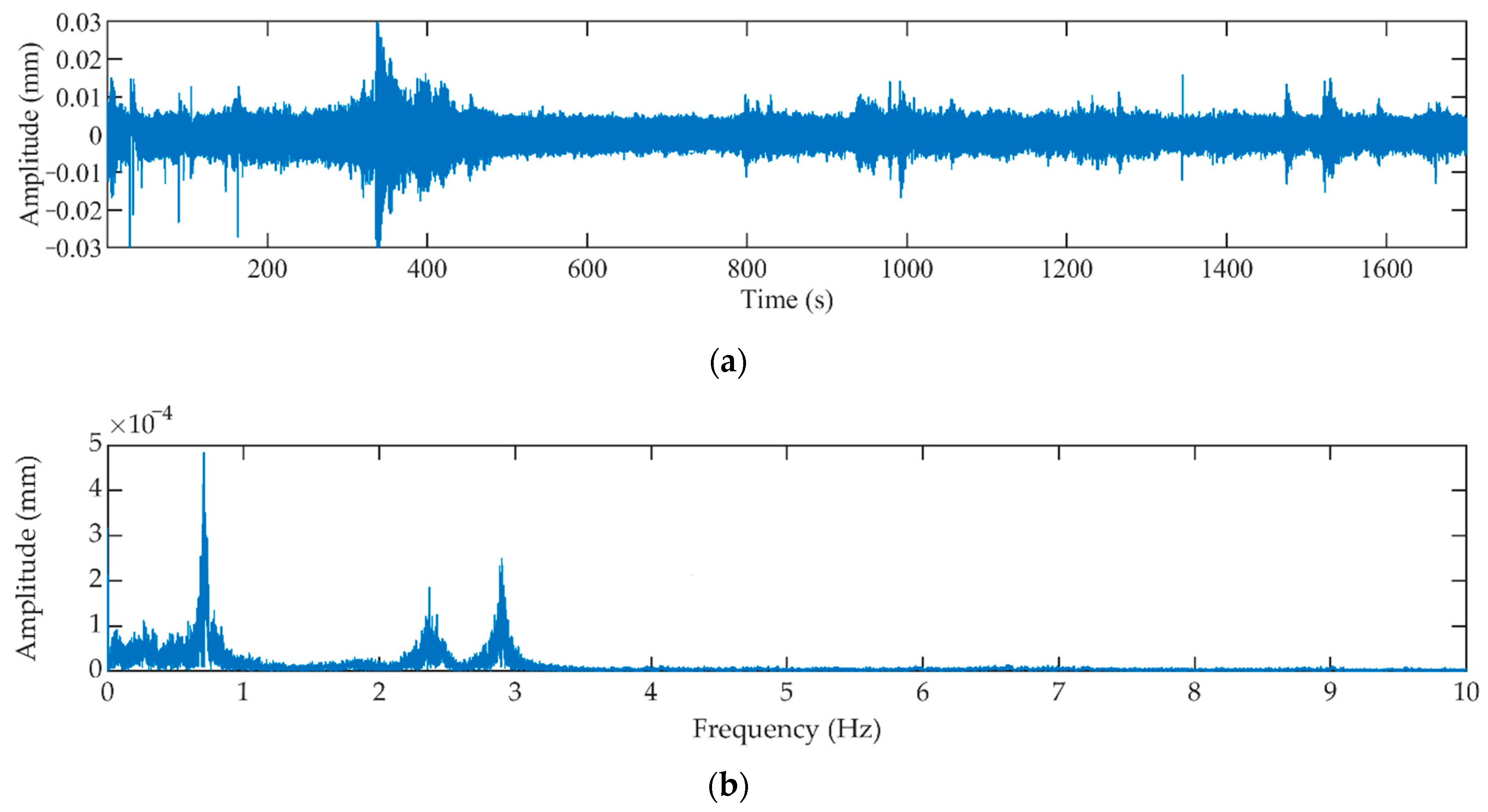
3.2. Analysis of the Vibration Tested Data Obtained from the Shang-Yuan Bridge’s Rotating Structure

The vibration sensor 891-4, made by the Institute of Engineering Mechanics (CES), was used to test the vibration of the bridge’s rotating structure. This sensor was installed at the end of a cantilever of the rotating structure to measure the vertical vibration time history. The vibration test lasted 1780s, during which all horizontal rotation processes occurred. The sampling frequency was 255 Hz. The time and frequency domain distributions of the tested vibration data are shown in Figure 5.
Three peaks of frequency in the discrete Fourier spectrum clearly corresponded to the first three order vibration modes of the rotating structure (see Table 1 and Figure 5b). No peaks were observed after those corresponding to the first three order vibration modes. Therefore, the contribution of the higher order mode was ignored. Figure 4b shows how the second order mode was symmetric and provided little contribution to the pier-bottom bending moment of the rotating structure. As a matter of fact, the stability of the rotating structure was mainly affected by the first two asymmetrical vibration modes (i.e., the first- and third-order vibration modes).

4. Derivation of the Relationship between the Pier-Bottom Bending Moment M and the Acceleration a

We deduced the analytical formula for calculating the pier-bottom bending moment M based on the acceleration a in the first two asymmetrical vibration modes. The first step was to simplify the rotating structure to a T-shape structure (Figure 6). In particular, the pier and the girder of the rotating structure were simplified to an infinite freedom degree straight rod with infinite axial stiffness. The shear deformations of the pier and of the girder were ignored. The top of the pier and the gravity center of the girder were connected by rigid rod; moreover, the bottom of the pier was hinged to the ground and connected with a rotational spring with stiffness k. For convenience, in the formula the pier is indicated as “rod 1” and the right cantilever beam as “rod 2”. Since it was assumed that the deformations of the left and right cantilevers were antisymmetric in the first antisymmetric vibration mode, the left cantilever was not numbered. The original position of rod 1 in the local coordinate system was at the pier bottom. The positive direction x1 corresponded to the up direction, while the positive direction of y1 corresponded to the right direction. The original position of rod 2 in the local coordinate system was at the cantilever’s support. In this case, the positive direction x2 was the right direction, while the positive direction y2 was the down direction.
According to the vibration regulation of the infinite freedom degree system, the displacement of any point on rods 1 and 2 in the directions y 1 ( x 1 , t ) and y 2 ( x 2 , t ) can be described by the following formula when considering an asymmetrical vibration mode [26]:
y 1 ( x 1 , t ) = Y 1 ( x 1 ) sin ( ω t + θ )
y 2 ( x 2 , t ) = Y 2 ( x 2 ) sin ( ω t + θ )
where ω is the mode circular frequency, θ is the phase angle, t is the time, and Y ( x ) is a shape function.
New parameters ( λ 1 and λ 2 ) were defined as follows:
λ 1 4 = ω 2 m ¯ 1 E 1 I 1
λ 2 4 = ω 2 m ¯ 2 E 2 I 2
where m ¯ 1 is the unit length mass of the pier, L 1 is the height of the pier, I 1 is the inertia moment of the pier section, E 1 is the elasticity modulus of the pier concrete, m ¯ 2 is the unit length mass of the cantilever, L 2 is the length of the cantilever, I 2 is the inertia moment of the cantilever section, and E 2 is the elasticity modulus of the cantilever concrete.
The general solutions of the shape functions Y 1 ( x 1 ) and Y 2 ( x 2 ) in a specified vibration mode can be described as follows:
Y 1 ( x 1 ) = C 1 cosh λ 1 x 1 + C 2 sinh λ 1 x 1 + C 3 cos λ 1 x 1 + C 4 sin λ 1 x 1
Y 2 ( x 2 ) = C 5 cosh λ 2 x 2 + C 6 sinh λ 2 x 2 + C 7 cos λ 2 x 2 + C 8 sin λ 2 x 2
where C 1 C 8 are undetermined coefficients.
Notably, the rotating structure should satisfy the following boundary conditions.
1.
The displacement of the pier bottom (rod 1) should be 0 (i.e., Y 1 ( 0 ) = 0 ); therefore:
C 1 + C 3 = 0
2.
The bending moment at the free end of the cantilever (rod 2) should be 0 (i.e., E 2 I 2 Y ¨ 2 ( L 2 ) = 0 ); therefore:
C 5 cosh λ 2 L 2 + C 6 sinh λ 2 L 2 C 7 cos λ 2 L 2 C 8 sin λ 2 L 2 = 0
3.
The shear force at the free end of the cantilever (rod 2) should be 0 (i.e., E 2 I 2 Y 2 ( L 2 ) = 0 ); therefore:
C 5 sinh λ 2 L 2 + C 6 cosh λ 2 L 2 + C 7 sin λ 2 L 2 C 8 cos λ 2 L 2 = 0
4.
The vertical displacement at the supported end of the cantilever (rod 2) should be 0 (i.e., Y 2 ( 0 ) = 0 ); therefore:
C 5 + C 7 = 0
5.
The rotation of the pier top (rod 1) should be equal to that of the cantilever (rod 2) at the supported end (i.e., Y ˙ 1 ( L 1 ) = Y ˙ 2 ( 0 ) ); therefore:
C 1 λ 1 sinh λ 1 L 1 + C 2 λ 1 cosh λ 1 L 1 C 3 λ 1 sin λ 1 L 1 + C 4 λ 1 cos λ 1 L 1 C 6 λ 2 C 8 λ 2 = 0
6.
The horizontal forces on the superstructure should balance each other.
When considering the superstructure containing two cantilevers as an isolator, the following formula should be satisfied according to Newton’s second law:
F = m a
where the horizontal force F is equal to the shear force at the pier top:
F = E 1 I 1 Y 1 ( L 1 ) sin ( ω t + θ )
Therefore, the mass of the isolator can be calculated as follows:
m = 2 m ¯ 2 L 2 + m s
where m s is the additional mass, which is used to guarantee the gross mass, and the rotational inertia of the superstructure are same as those of the actual structure after its simplification to a prismatic straight rod.
The acceleration of the isolator can be calculated by the following formula:
a = 2 ( y 1 + h k y 1 x 1 ) t 2 = ω 2 [ Y 1 ( L 1 ) + h k Y ˙ 1 ( L 1 ) ] sin ( ω t + θ )
where h k is the distance from pier top to the section gravity center of the cantilever.
If Equations (13)–(15) are substituted into Equation (12), then:
[ E 1 I 1 λ 1 3 sinh λ 1 L 1 + ω 2 ( 2 m ¯ 2 L 2 + m s ) ( cosh λ 1 L 1 + h k λ 1 sinh λ 1 L 1 ) ] C 1 + [ E 1 I 1 λ 1 3 cosh λ 1 L 1 + ω 2 ( 2 m ¯ 2 L 2 + m s ) ( sinh λ 1 L 1 + h k λ 1 cosh λ 1 L 1 ) ] C 2 + [ E 1 I 1 λ 1 3 sin λ 1 L 1 + ω 2 ( 2 m ¯ 2 L 2 + m s ) ( cos λ 1 L 1 h k λ 1 sin λ 1 L 1 ) ] C 3 + [ ω 2 ( 2 m ¯ 2 L 2 + m s ) ( sin λ 1 L 1 + h k λ 1 cos λ 1 L 1 ) E 1 I 1 λ 1 3 cos λ 1 L 1 ] C 4 = 0
7.
According to the moment balance at the pier top (i.e., E 1 I 1 Y ¨ 1 ( L 1 ) + h k E 1 I 1 Y 1 ( L 1 ) = 2 E 2 I 2 Y ¨ 2 ( 0 ) ), then:
E 1 I 1 λ 1 2 ( cosh λ 1 L 1 + h k λ 1 sinh λ 1 L 1 ) C 1 + E 1 I 1 λ 1 2 ( sinh λ 1 L 1 + h k λ 1 cosh λ 1 L 1 ) C 2 + E 1 I 1 λ 1 2 ( h k λ 1 sin λ 1 L 1 cos λ 1 L 1 ) C 3 E 1 I 1 λ 1 2 ( sin λ 1 L 1 + h k λ 1 cos λ 1 L 1 ) C 4 2 E 2 I 2 λ 2 2 C 5 + 2 E 2 I 2 λ 2 2 C 7 = 0
8.
According to the moment balance at the pier bottom (i.e., E 1 I 1 Y ¨ 1 ( 0 ) sin ( ω t + θ ) = k Y ˙ 1 ( 0 ) sin ( ω t + θ ) ), then:
E 1 I 1 C 1 λ 1 2 + k C 2 λ 1 E 1 I 1 C 3 λ 1 2 + k C 4 λ 1 = 0
where k is the rotating stiffness of the upper turntable.
Equations (7)–(11) and Equations (16)–(18) form an equation that can be used to calculate C 1 C 8 . The determinants of the equation set are shown below:
| 1 0 0 0 λ 1 sinh λ 1 L 1 [ E 1 I 1 λ 1 3 sinh λ 1 L 1 + ω 2 ( 2 m ¯ 2 L 2 + m s ) × ( cosh λ 1 L 1 + h k λ 1 sinh λ 1 L 1 ) ] E 1 I 1 λ 1 2 ( cosh λ 1 L 1 + h k λ 1 sinh λ 1 L 1 ) E 1 I 1 λ 1 2 0 0 0 0 λ 1 cosh λ 1 L 1 [ E 1 I 1 λ 1 3 cosh λ 1 L 1 + ω 2 ( 2 m ¯ 2 L 2 + m s ) × ( sinh λ 1 L 1 + h k λ 1 cosh λ 1 L 1 ) ] E 1 I 1 λ 1 2 ( sinh λ 1 L 1 + h k λ 1 cosh λ 1 L 1 ) k λ 1 1 0 0 0 λ 1 sin λ 1 L 1 [ E 1 I 1 λ 1 3 sin λ 1 L 1 + ω 2 ( 2 m ¯ 2 L 2 + m s ) × ( cos λ 1 L 1 h k λ 1 sin λ 1 L 1 ) ] E 1 I 1 λ 1 2 ( h k λ 1 sin λ 1 L 1 cos λ 1 L 1 ) E 1 I 1 λ 1 2 0 0 0 0 λ 1 cos λ 1 L 1 [ ω 2 ( 2 m ¯ 2 L 2 + m s ) ( sin λ 1 L 1 + h k λ 1 cos λ 1 L 1 ) E 1 I 1 λ 1 3 cos λ 1 L 1 ] E 1 I 1 λ 1 2 ( sin λ 1 L 1 + h k λ 1 cos λ 1 L 1 ) k λ 1 0 cosh λ 2 L 2 sinh λ 2 L 2 1 0 0 2 E 2 I 2 λ 2 2 0 0 sinh λ 2 L 2 cosh λ 2 L 2 0 λ 2 0 0 0 0 cos λ 2 L 2 sin λ 2 L 2 1 0 0 2 E 2 I 2 λ 2 2 0 0 sin λ 2 L 2 cos λ 2 L 2 0 λ 2 0 0 0 |
C 1 C 8 cannot equal to 0 at the same time; therefore, the determinant should be 0. An equation for calculating the circular frequency (ω) can be obtained by substituting Equations (3) and (4) into Equation (19). The ω of each order vibration mode can be solved using this equation; furthermore, the normalized solution of the undetermined coefficients C 1 C 8 can obtained by substituting the ω of the concerned vibration mode into Equation (19).
According to engineering experience, the vertical acceleration at the free end of the cantilever and the horizontal acceleration along the girder at the pier top are more suitable to be monitored. The formulas providing the maximum values of horizontal acceleration at the pier top and of vertical acceleration at the free end of the cantilever in a specified vibration mode are shown below:
a h = ω 2 [ Y 1 ( L 1 ) + h k Y ˙ 1 ( L 1 ) ] = ω 2 [ C 1 cosh λ 1 L 1 + C 2 sinh λ 1 L 1 + C 3 cos λ 1 L 1 + C 4 sin λ 1 L 1   + h k ( C 1 λ 1 sinh λ 1 L 1 + C 2 λ 1 cosh λ 1 L 1 C 3 λ 1 sin λ 1 L 1 + C 4 λ 1 cos λ 1 L 1 ]
a v = ω 2 Y 2 ( L 2 ) = ω 2 [ C 5 cosh λ 2 L 2 + C 6 sinh λ 2 L 2 + C 7 cos λ 2 L 2 + C 8 sin λ 2 L 2 ]
The maximum bending moment at the pier bottom in a specified vibration mode can be calculated as follows:
M max   = E 1 I 1 Y ¨ 1 ( 0 )   = E 1 I 1 ( C 1 λ 1 2 cosh 0 + C 2 λ 1 2 sinh 0 C 3 λ 1 2 cos 0 C 4 λ 1 2 sin 0 )   = E 1 I 1 C 1 λ 1 2 E 1 I 1 C 3 λ 1 2
Furthermore, the ratio of the vertical acceleration at the end cantilever ( a v ) and the horizontal acceleration at the pier top ( a h ) to the bending moment of the pier bottom can be obtained by substituting ω and C 1 C 8 into Equations (20)–(22):
μ = a h M 1 i
μ = a v M 1 i

5. Verification by the FEM

To verify the reliability of the analytical formulas described above, we considered a typical high-speed railway continuous bridge and four finite element models with span combinations 40 m + 64 m + 40 m, 48 m + 80 m + 48 m, 60 m + 100 m + 60 m, and 70 m + 125 m + 70 m. The calculated and the simulated results were then compared.
The superstructures of the models were built based on the blueprint of a standard double-line continuous bridge of a high-speed railway with a design speed of 350 km/h. The substructures in the models were instead based on the actual project of the Zhengzhou–Xuzhou high-speed railway. The elastic modulus of the pier concrete was 31,500 MPa, the bulk density 25,000 N/m3, and the standard compressive strength 20.1 MPa. Meanwhile, the concrete of the upper turntable and of the continuous beam had an elastic modulus of 35,500 MPa, a bulk density of 25,000 N/m3, and a standard compressive strength of 32.4 MPa. At the center of the upper turntable, the translation motion in the X, Y, and Z directions and the rotation in the X and Z directions were constrained to simulate the constraint conditions of the spherical hinge. At the edge of the upper turntable, the translational motion in the Z direction was constrained to simulate the action of the rotational spring ( k ). A time history analysis was conducted using the FEM. The forced displacement load of the sine function was applied on the position of the upper turntable bracing. The amplitude of the forced displacement load was 1 mm, and the frequency of the load corresponded to the vibration mode frequency of the rotating structure. The parameters of the materials were obtained from the design code of the Chinese railway bridge [27,28].
The geometric parameters of four typical continuous bridges are shown in Table 2. We considered pier heights of 10 m, 20 m, 30 m, and 40 m; moreover, the a v / M and a h / M ratios were calculated by Equations (23) and (24), respectively.
The parameters of the analytical formula were calculated as follows.
1.
Unit length mass of the pier
m ¯ 1 = A 1 × ρ
where A 1 is the section area of the pier and ρ is the density of the pier concrete.
2.
Unit length mass of the girder
This was calculated by assuming that the rotational inertia would be equal to that of the actual girder after it was simplified to a straight rod:
2 3 m ¯ 2 L 2 3 = i = 1 n m i L i 2
where m ¯ 2 is the equivalent unit length mass of the girder, m i is the mass of the ith cantilever segment (for a total of n segments on the rotating structure) and L i is the distance from the gravity center of the ith cantilever segment.
3.
Additional point mass (ms)
This point was located at the supported end of the cantilever. Its value was calculated assuming that the gross mass would be equal to that of the actual girder after it was simplified to a straight rod. The formula used to calculate ms was the following:
m s = i = 1 n m i 2 m ¯ 2 L 2
4.
Rotating stiffness of the upper turntable
k = 3 E I L
where E is the elasticity modulus of the upper turntable concrete, I the section inertia moment of the upper turntable element connecting the pier bottom and the supporter, and L the length of the upper turntable element.
5.
Distance between the pier top and the gravity center of the cantilever section
h k = h 0 1 2 h z
where h 0 is the section height at the cantilever supported end and h z is the section height at the midpoint of the cantilever.
The parameters of the analytical formula used for the four-span combination continuous bridges are listed in Table 3.
The ratio of acceleration to the pier-bottom bending moments, which were obtained by applying the analytical formula and through the finite element analysis, are shown in Figure 7 and Figure 8. We noticed the following.
1.
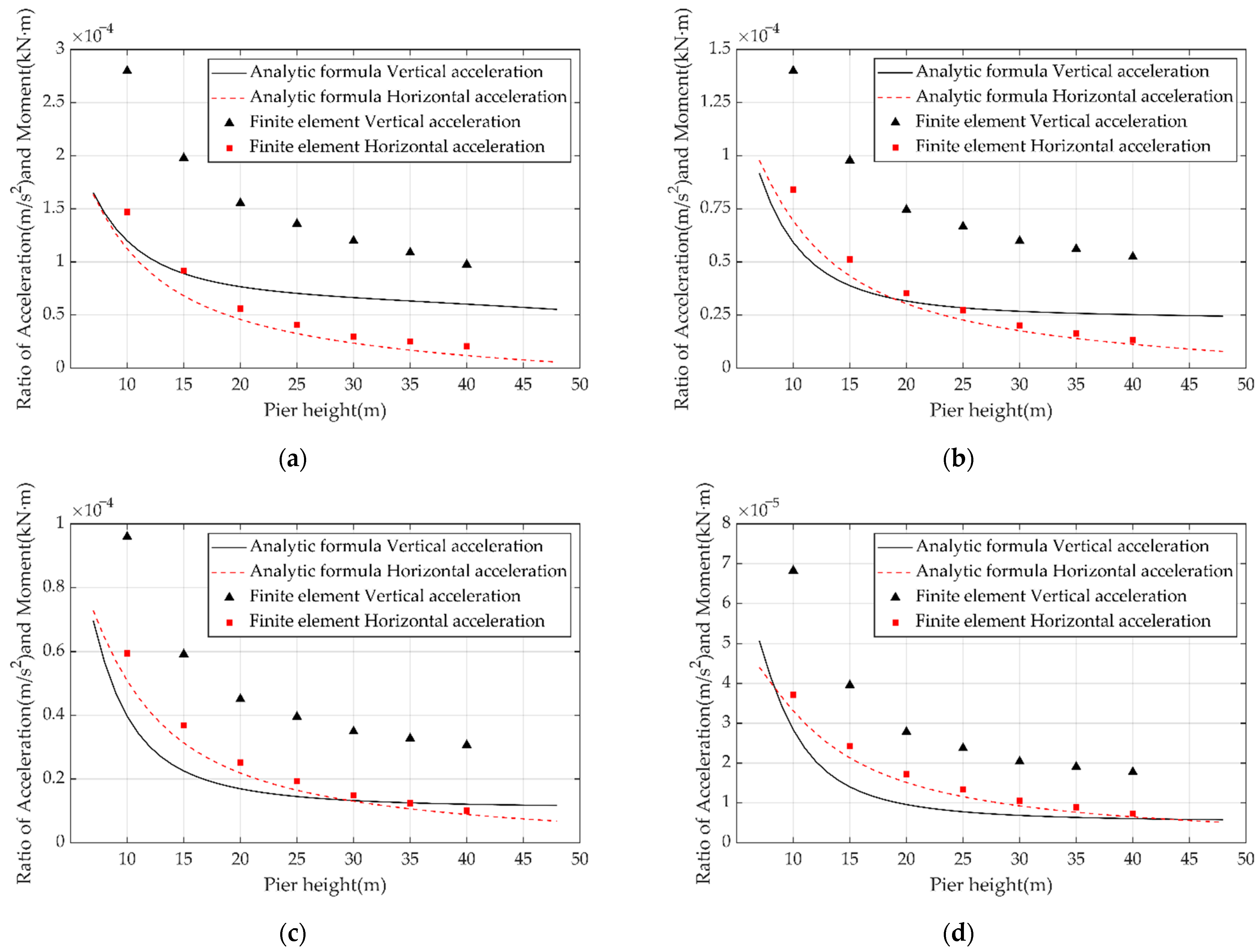
The trends of acceleration of the pier-bottom bending moment calculated through the analytical formula were basically consistent with the results of the finite element analysis. Hence, it is acceptable to calculate the pier-bottom bending moment of the rotating structure based on the acceleration and using the analytical formula.
2.
The ratio of the horizontal acceleration at the pier top ( a h ) to the pier-bottom bending moment calculated through the analytical formula was more similar to the simulated FEM results than to the ratio of the vertical acceleration at the end cantilever ( a v ). It can be seen from the analysis that, in order to simplify the calculation, the variable section beam is simplified as an equal section support rod, which makes a certain difference in the stiffness of the main beam between the analytical formula and the finite element. This difference affects the vertical acceleration response of the cantilever end and reduces the calculation accuracy of the analytical formula. As for the horizontal acceleration at the top of the pier, the main factor affecting its response is the pier stiffness rather than the girder stiffness. However, both the analytical formula and the finite element simulation show that the pier is of an equal section, so the ratio of the horizontal acceleration at the top of the pier calculated by the analytical formula to the bending moment at the bottom of the pier is closer to the finite element simulation result.
3.
The horizontal acceleration at the pier top ( a h ) can be used to calculate the bending moment of the pier bottom and to evaluate the stability of the rotating structure, because the horizontal acceleration is not affected by the symmetric vibration mode of the girder.

6. Recommend Formula for Calculating the Allowable Acceleration

Through the above analyses, we established that the horizontal acceleration at the pier top ( a h ) can be used to calculate the pier-bottom bending moment of the rotating structure. The structure can vibrate in the first- or second-order asymmetric vibration modes, or even simultaneously in both modes. The maximum allowed acceleration at the pier top ( a h ) can be calculated by Equation (30) if the structure vibrates in the first-order asymmetric vibration mode or calculated by Equation (31) if it vibrates in the second-order asymmetric vibration mode. Additionally, if the structure vibrates simultaneously in both modes, it can be assumed that the vibration peak of the first two order asymmetric modes is superimposed on the absolute value; the phase difference between the first two order asymmetric modes is not yet clear. Therefore, the maximum allowed acceleration at the pier top ( a h ) can be calculated by Equation (32) if the structure vibrates simultaneously in both modes: to ensure safety during the rotation process, this value can be considered equal to the minimum value calculated by Equations (30)–(32):
a h 1 = μ 1 · M a φ
a h 2 = μ 2 · M a φ
a h 12 = ( μ 1 + β μ 2 ) · M a φ ( 1 + β )
where μ 1 and μ 2 are the ratios of the horizontal acceleration at the pier top to the pier-bottom bending moment in the first- and second-order asymmetrical vibration mode, which can be calculated using Equation (23). For a typical high-speed railway bridge, the values of μ 1 and μ 2 can be calculated directly from Table 4 and Table 5 by linear interpolation. In Equations (30)–(32), β is the ratio of the pier-bottom bending moment contributed by the first-order asymmetrical vibration mode to that contributed by the second-order asymmetrical vibration mode; values between 1–3 are recommended for this parameter. M a represents the ultimate bearing moment of the upper turntable, while φ is the safety factor (recommend value = 2.0).

7. Conclusions

To ensure the safety of bridges constructed by the horizontal rotation method during the rotation process, we deduced an analytic formula to calculate the ratio of vibration acceleration and the pier-bottom section bending moment for the rotating structure. The calculation results obtained from the analytic formula were compared with those from the FEM calculations. Our main conclusions are given below.
  • The vibration of the rotating structure in the facade is mainly influenced by the first three order vibration modes; meanwhile, the pier-bottom section bending moment (which is directly related to the rotating structure stability) is only affected by the first two order asymmetric vibration modes.
  • The analytic formula, which considers the cantilever beam and the pier as an infinite-degree-of-freedom rod, can describe the relationship between the vibration acceleration and the pier-bottom bending moment.
  • The allowed maximum acceleration at the pier top (ah) should correspond to the minimum value calculated to ensure safety during the rotation process.
  • The simplified form of the main beam reduces the accuracy of calculating the vertical acceleration of the cantilever end by the analytical formula, and a more optimized simplified form needs further study. Furthermore, the ratio of the pier-bottom bending moment in the first asymmetric mode to that in the second asymmetric mode is not sufficient for accurate evaluations and need further research.

Author Contributions

Conceptualization, W.Z. and K.L.; methodology, Y.C. and K.L.; software, K.L.; validation, W.Z. and Y.C.; formal analysis, Y.C.; investigation, W.Z.; data curation, K.L.; writing—original draft preparation, K.L.; writing—review and editing, K.L. All authors have read and agreed to the published version of the manuscript.

Funding

This research was funded by the National Natural Science Foundation of China, grant number 51778022.

Institutional Review Board Statement

Not applicable.

Informed Consent Statement

Not applicable.

Data Availability Statement

All data generated or analyzed during this study are included in this article.

Acknowledgments

This work was supported by the National Natural Science Foundation of China (Grant No. 51778022).

Conflicts of Interest

On behalf of all authors, the corresponding author states that there is no conflict of interest.

References

  1. Su, M.; Wang, J.; Peng, H.; Cai, C.S.; Dai, G. State-of-the-art review of the development and application of bridge rotation construction methods in China. Sci. China Technol. Sc. 2020, 64, 1137–1152. [Google Scholar] [CrossRef]
  2. Feng, Y.; Qi, J.N.; Wang, J.Q.; Zhang, W.X.; Zhang, Q.F. Rotation construction of heavy swivel arch bridge for high-speed railway. Structures 2020, 26, 755–764. [Google Scholar] [CrossRef]
  3. Siwowski, T.; Wysocki, A. Horizontal Rotation via Floatation as an Accelerated Bridge Construction for Long-Span Footbridge Erection: Case Study. J. Bridge Eng. 2015, 20, 05014014. [Google Scholar] [CrossRef]
  4. Zhang, J.; El-Diraby, T.E. Constructability analysis of the bridge superstructure rotation construction method in China. J. Constr. Eng. Manag. 2006, 132, 353–362. [Google Scholar] [CrossRef]
  5. Che, X.J.; Zhang, X.D. Stability Impact Analysis of Random Dead Load Distribution to T-rigid Frame Bridge Swivel Construction. Appl. Mech. Mater. 2013, 361–363, 1348–1352. [Google Scholar]
  6. Idris, N.S.; Boon, K.H.; Kamarudin, A.F.; Sooria, S.Z. Ambient Vibration Test on Reinforced Concrete Bridges. In Proceedings of the The 3rd International Conference on Civil and Environmental Engineering for Sustainability (IConCEES 2015), Melaka, Malaysia, 1–2 December 2015; EDP Sciences: Les Ulis, France, 2016; Volume 47, p. 02012. [Google Scholar] [CrossRef]
  7. Chen, G.W.; Omenzetter, P.; Beskhyroun, S. Operational modal analysis of an eleven-span concrete bridge subjected to weak ambient excitations. Eng. Struct. 2017, 151, 839–860. [Google Scholar] [CrossRef]
  8. Nguyen, K.; Camara, A.; Rio, O.; Sparowitz, L. Dynamic Effects of Turbulent Crosswind on the Serviceability State of Vibrations of a Slender Arch Bridge Including Wind-Vehicle-Bridge Interaction. J. Bridge Eng. 2017, 22, 06017005. [Google Scholar] [CrossRef] [Green Version]
  9. Niu, H.W.; Zhu, J.; Chen, Z.Q.; Zhang, W. Dynamic Performance of a Slender Truss Bridge Subjected to Extreme Wind and Traffic Loads Considering 18 Flutter Derivatives. J. Aerosp. Eng. 2019, 32, 04019082. [Google Scholar] [CrossRef]
  10. Martinez-Rodrigo, M.D.; Andersson, A.; Pacoste, C.; Karoumi, R. Resonance and cancellation phenomena in two-span continuous beams and its application to railway bridges. Eng. Struct. 2020, 222, 105316. [Google Scholar] [CrossRef]
  11. Wu, S.W.; Li, H.Q.; Wang, X.; Li, R.; Tian, C.Y.; Hou, Q.S. Seismic performance of a novel partial precast RC shear wall with reserved cast-in-place base and wall edges. Soil Dyn. Earthq. Eng. 2022, 152, 107038. [Google Scholar] [CrossRef]
  12. Raftoyiannis, I.G. Parametric resonance of steel bridges pylons due to periodic traffic loads. Arch. Appl. Mech. 2012, 82, 1601–1611. [Google Scholar] [CrossRef]
  13. Wei, M.H.; Xiao, Y.Q.; Liu, H.T.; Lin, K. Nonlinear responses of a cable-beam coupled system under parametric and external excitations. Arch. Appl. Mech. 2014, 84, 173–185. [Google Scholar] [CrossRef]
  14. Moughty, J.J.; Casas, J.R. Performance Assessment of Vibration Parameters as Damage Indicators for Bridge Structures under Ambient Excitation. Procedia Eng. 2017, 199, 1970–1975. [Google Scholar] [CrossRef] [Green Version]
  15. Dos Santos, R.C.; Larocca, A.P.C.; Neto, J.O.D.; Barbosa, A.C.B.; Oliveira, J.V.M. Detection of a curved bridge deck vibration using robotic total stations for structural health monitoring. J. Civ. Struct. Health 2019, 9, 63–76. [Google Scholar] [CrossRef]
  16. Breuer, P.; Chmielewski, T.; Gorski, P.; Konopka, E.; Tarczynski, L. Monitoring horizontal displacements in a vertical profile of a tall industrial chimney using Global Positioning System technology for detecting dynamic characteristics. Struct. Control. Health Monit. 2015, 22, 1002–1023. [Google Scholar] [CrossRef]
  17. Yang, D.H.; Yi, T.H.; Li, H.N.; Zhang, Y.F. Monitoring and analysis of thermal effect on tower displacement in cable-stayed bridge. Measurement 2018, 115, 249–257. [Google Scholar] [CrossRef]
  18. Yang, D.H.; Yi, T.H.; Li, H.N.; Zhang, Y.F. Correlation-Based Estimation Method for Cable-Stayed Bridge Girder Deflection Variability under Thermal Action. J. Perform. Constr. Facil. 2018, 32, 04018070. [Google Scholar] [CrossRef]
  19. Thurgood, T.; Halling, M.W.; Barr, P.J. Structural Health Monitoring of the Cherry Hill Bridge. In Structures Congress 2006; American Society of Civil Engineers: Reston, VA, USA, 2006. [Google Scholar]
  20. Banerjee, S.; Chi, C.; Shinozuka, M. Kalman Filter-Based Identification of Bridge Fragility Parameters. In Structures Congress 2011; American Society of Civil Engineers: Reston, VA, USA, 2011. [Google Scholar]
  21. Feng, M.Q.; Kim, D.K.; Yi, J.H.; Chen, Y.B. Baseline models for bridge performance monitoring. J. Eng. Mech. 2004, 130, 562–569. [Google Scholar] [CrossRef] [Green Version]
  22. Wen, Y.K.; Sun, L.M. Distributed ATMD for Buffeting Control of Cable-Stayed Bridges Under Construction. Int. J. Struct. Stab. Dy. 2015, 15, 1450054. [Google Scholar] [CrossRef]
  23. Hua, X.G.; Wang, C.Q.; Li, S.L.; Chen, Z.Q. Experimental investigation of wind-induced vibrations of main cables for suspension bridges in construction phases. J. Fluid Struct. 2020, 93, 102846. [Google Scholar] [CrossRef]
  24. Giordano, P.F.; Limongelli, M.P. Response-based time-invariant methods for damage localization on a concrete bridge. Struct. Concr. 2020, 21, 1254–1271. [Google Scholar] [CrossRef]
  25. Yan, L.; Ren, L.; He, X.H.; Lu, S.Y.; Guo, H.; Wu, T. Strong Wind Characteristics and Buffeting Response of a Cable-Stayed Bridge under Construction. Sensors 2020, 20, 1228. [Google Scholar] [CrossRef] [Green Version]
  26. Clough, R.W.; Penzien, J. Dynamics of Structures, 2nd ed.; Computers and Structures: Berkeley, CA, USA, 2010. [Google Scholar]
  27. Railway Engineering Consulting Group Co., Ltd. Code for Design on Reinforced and Prestressed Concrete Structure of Railway Bridge and Culvert; China Railway Publishing House: Beijing, China, 2005. [Google Scholar]
  28. China Railway Siyuan Survey and Design Group Co., Ltd. Code for Design on Railway Bridge and Culvert; China Railway Publishing House: Beijing, China, 2017. [Google Scholar]
Figure 1. The special construction process of horizontal rotation construction method. (a) Rotating system construction, (b) Unbalanced weighting, (c) Balance counterweight, (d) Trial rotation, (e) Formal rotation, (f) Monitoring.
Sustainability 14 05853 g001
Figure 2. Structure diagram of the rotating system.
Sustainability 14 05853 g002
Figure 3. Tensile diagram of the rotating system.
Sustainability 14 05853 g003
Figure 4. Vibration modes of the Shang-Yuan bridge rotating structure. (a) First-order vibration mode (First-order asymmetric vibration mode), (b) Second-order vibration mode (First-order symmetric vibration mode), (c) Third-order vibration mode (Second-order asymmetric vibration mode).
Sustainability 14 05853 g004
Figure 5. Vibration displacement time and frequency domain distributions for the Shang-Yuan bridge rotating structure. (a) Displacement time history of vertical vibration, (b) Discrete Fourier spectrum.
Sustainability 14 05853 g005
Figure 6. Diagram of the rotating structure.
Sustainability 14 05853 g006
Figure 7. Acceleration and pier-bottom bending moment ratios of the rotating structure vibrating in the first asymmetric vibration mode. (a) Span: 40 m + 64 m + 40 m, (b) Span: 48 m + 80 m + 48 m, (c) Span: 60 m + 100 m + 60 m, (d) Span: 70 m + 125 m + 70 m.
Sustainability 14 05853 g007
Figure 8. Acceleration and pier-bottom bending moment ratios of the rotating structure vibrating in the second asymmetric vibration mode. (a) Span: 40 m + 64 m + 40 m, (b) Span: 48 m + 80 m + 48 m, (c) Span: 60 m + 100 m + 60 m, (d) Span: 70 m + 125 m + 70 m.
Sustainability 14 05853 g008
Table 1. Results of the vibration mode analysis.
Vibration ModeMode ShapeVibration Frequency (Hz)Sum of the Modal Participating Mass Ratios (%)Mode Directional Factor (%)
DXRYDZDXRYDZ
1Vibration of the main beam along the bridge0.727827.3168.440.0028.5271.480.00
2First-order symmetric bending of the main beam2.499427.3168.4433.320.000.00100.00
3First-order antisymmetric bending of the main beam2.982781.5385.3633.3276.2123.790.00
4Second-order antisymmetric bending of the main beam8.336384.0086.7033.3264.8435.080.08
Note: DX = translational freedom degree along the bridge, DZ = vertical translational freedom degree, RY = rotational freedom degree around the Y axis.
Table 2. Geometric parameters of the bridge substructure.
Span Combination (m)40 + 64 + 4048 + 80 + 4860 + 100 + 6070 + 125 + 70
PierCross-section width (cm)9009609001000
Cross-section height (cm)360360400400
Cross-section area (m2)29.61931.77932.56636.566
Section inertia moment (m4)29.24031.57339.23344.566
Upper turntableRadius of the brace slideway (m)4.04.54.55.0
Thickness of the upper turntable (m)2.02.52.53.0
Thickness of the down turntable (m)8.09.09.010.0
Table 3. Parameters of the four span combination continuous bridges.
Span Combination (m)40 + 64 + 4048 + 80 + 4860 + 100 + 6070 + 125 + 70
m ¯ 1 —Unit length mass of the pier (kg/m)7.5512 × 10+48.1019 × 10+48.3027 × 10+49.3224 × 10+4
E 1 —Elastic modulus of the pier concrete (N/m2)3.30 × 10+103.30 × 10+103.30 × 10+103.30 × 10+10
I 1 —Moment inertia of the pier (m4)29.24031.57339.23344.566
m ¯ 2 —Equivalent unit length mass of the girder (kg/m)3.0127 × 10+43.3027 × 10+44.0094 × 10+44.1386 × 10+4
E 2 — Elastic modulus of the main girder (N/m2)3.55 × 10+103.55 × 10+103.55 × 10+103.60 × 10+10
I 2 —Moment inertia of the girder (m4)28.43842.66979.469108.016
L 2 —Cantilever length of the girder (m)31.039.049.061.5
m s — Additional mass (kg)3.7373 × 10+55.7178 × 10+58.8476 × 10+51.5798 × 10+6
h 0 —Section height at the cantilever supported end (m)6.056.657.859.20
h z —Section height at the midpoint of the cantilever (m)3.794.465.586.37
k —Rotating stiffness of the upper turntable (N·m)1.4200 × 10+112.7734 × 10+112.7734 × 10+114.7925 × 10+11
Table 4. Values of μ 1 for a typical high-speed railway bridge.
μ 1 = a h 1 / M
10−6(m/s2)/(kN·m)
Span Combination (m)
40 + 64 + 4048 + 80 + 48
Rotating stiffness of the upper turntable (N·m)1.00 × 10+112.00 × 10+115.00 × 10+111.00 × 10+112.00 × 10+115.00 × 10+11
Moment inertia of the pier (m4)259025902590259025902590
Height of the pier (m)149.3313.558.9012.768.5011.544.397.074.166.563.955.85
189.2912.678.9612.218.6611.484.597.044.386.664.206.12
228.9711.538.7411.288.5310.894.666.794.486.524.346.14
268.4910.388.3310.258.2010.064.636.414.496.234.375.97
307.939.307.849.257.769.174.535.984.425.864.335.68
347.358.347.308.337.268.324.385.544.305.474.235.37
μ 1 = a h 1 / M
10−6(m/s2)/(kN·m)
Span Combination (m)
60 + 100 + 6070 + 125 + 70
Rotating stiffness of the upper turntable (N·m)1.00 × 10+112.00 × 10+115.00 × 10+111.00 × 10+112.00 × 10+115.00 × 10+11
Moment inertia of the pier (m4)259025902590259025902590
Height of the pier (m)141.763.111.672.901.592.610.811.490.761.390.731.26
181.903.251.803.051.732.800.881.600.831.490.801.36
221.993.291.903.121.832.900.931.660.891.560.861.44
262.063.261.973.121.912.940.981.700.941.610.911.50
302.093.182.023.061.962.921.021.720.981.630.951.53
342.103.072.042.981.992.871.051.711.011.630.981.55
Table 5. Values of μ 2 for a typical high-speed railway bridge.
μ 2 = a h 2 / M
/10−6(m/s2)/(kN·m)
Span Combination (m)
40 + 64 + 4048 + 80 + 48
Rotating stiffness of the upper turntable (N·m)1.00 × 10+112.00 × 10+115.00 × 10+111.00 × 10+112.00 × 10+115.00 × 10+11
Moment inertia of the pier (m4)259025902590259025902590
Height of the pier (m)1480.80112.4165.9674.6257.5552.9959.7782.8549.0355.8342.8840.24
1856.6689.3547.5160.2942.3543.5742.1364.0535.5043.9431.7132.38
2241.8670.8335.8848.8832.5236.2031.7250.8027.2735.4924.7226.69
2631.8055.1127.8139.1525.5929.9224.9040.7821.7429.0519.9522.31
3024.4441.5321.8230.6220.3724.3320.0832.8117.7723.8916.4718.76
3418.7529.8117.1223.1016.2419.2816.4726.2514.7619.5913.8015.78
μ 2 = a h 2 / M
/10−6(m/s2)/(kN·m)
Span Combination (m)
60 + 100 + 6070 + 125 + 70
Rotating stiffness of the upper turntable (N·m)1.00 × 10+112.00 × 10+115.00 × 10+111.00 × 10+112.00 × 10+115.00 × 10+11
Moment inertia of the pier (m4)259025902590259025902590
Height of the pier (m)1441.5663.1734.1042.5629.7930.5030.6547.3425.1831.9622.0122.90
1829.2446.3724.6932.0722.0623.7621.5634.1618.2523.7916.3217.73
2222.1535.6619.0925.2017.3319.1516.3725.9714.1518.5312.8614.20
2617.6128.3615.4220.4214.1515.8413.0420.5411.4614.9510.5411.71
3014.4623.0912.8216.9111.8713.3510.7616.749.5712.398.899.88
3412.1519.0810.8814.2110.1611.419.0913.958.1710.487.648.49
Publisher’s Note: MDPI stays neutral with regard to jurisdictional claims in published maps and institutional affiliations.

