
Exergetic Analysis of a Natural Gas Combined-Cycle Power Plant with a Molten Carbonate Fuel Cell for Carbon Capture


Abstract
:1. Introduction
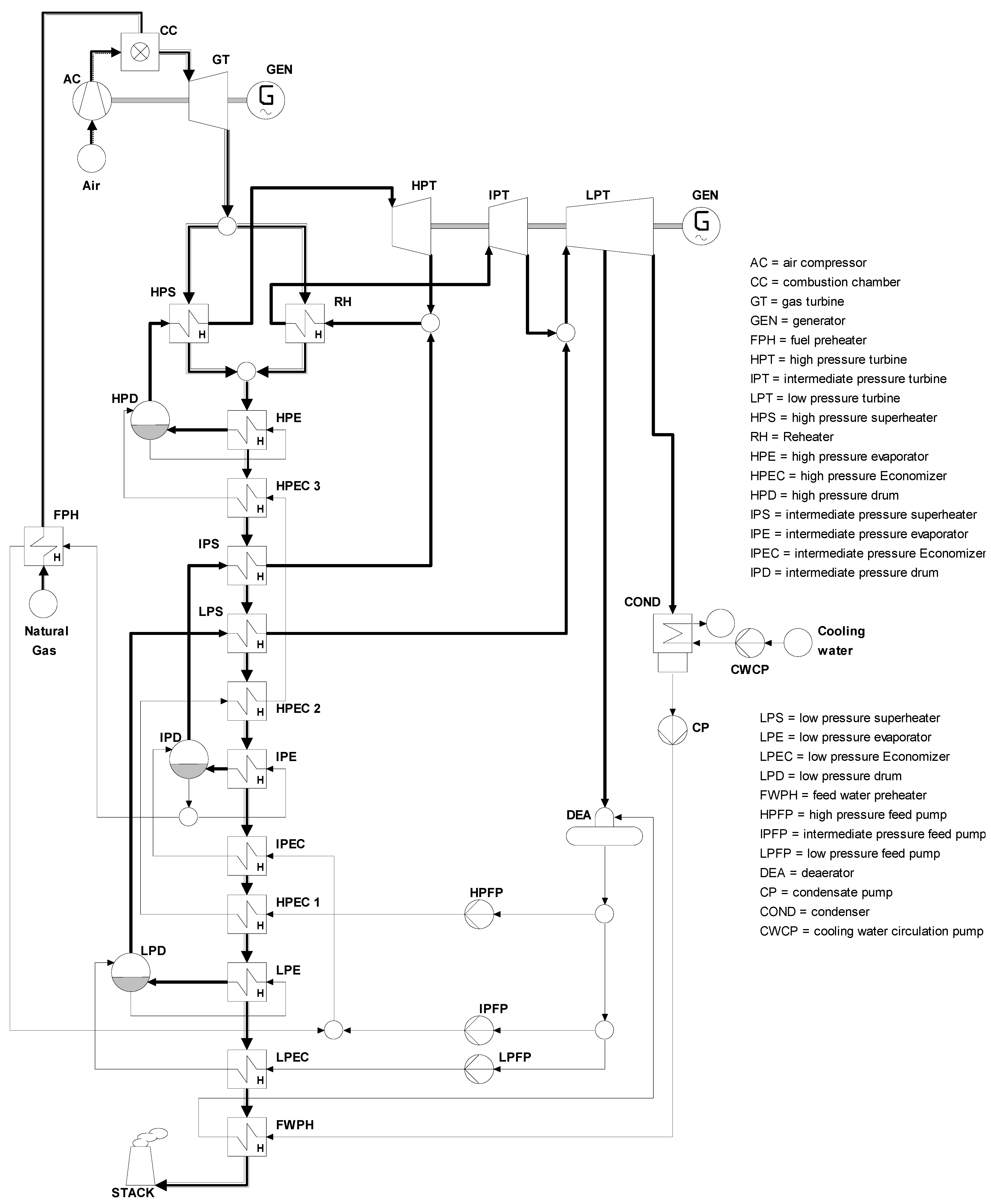
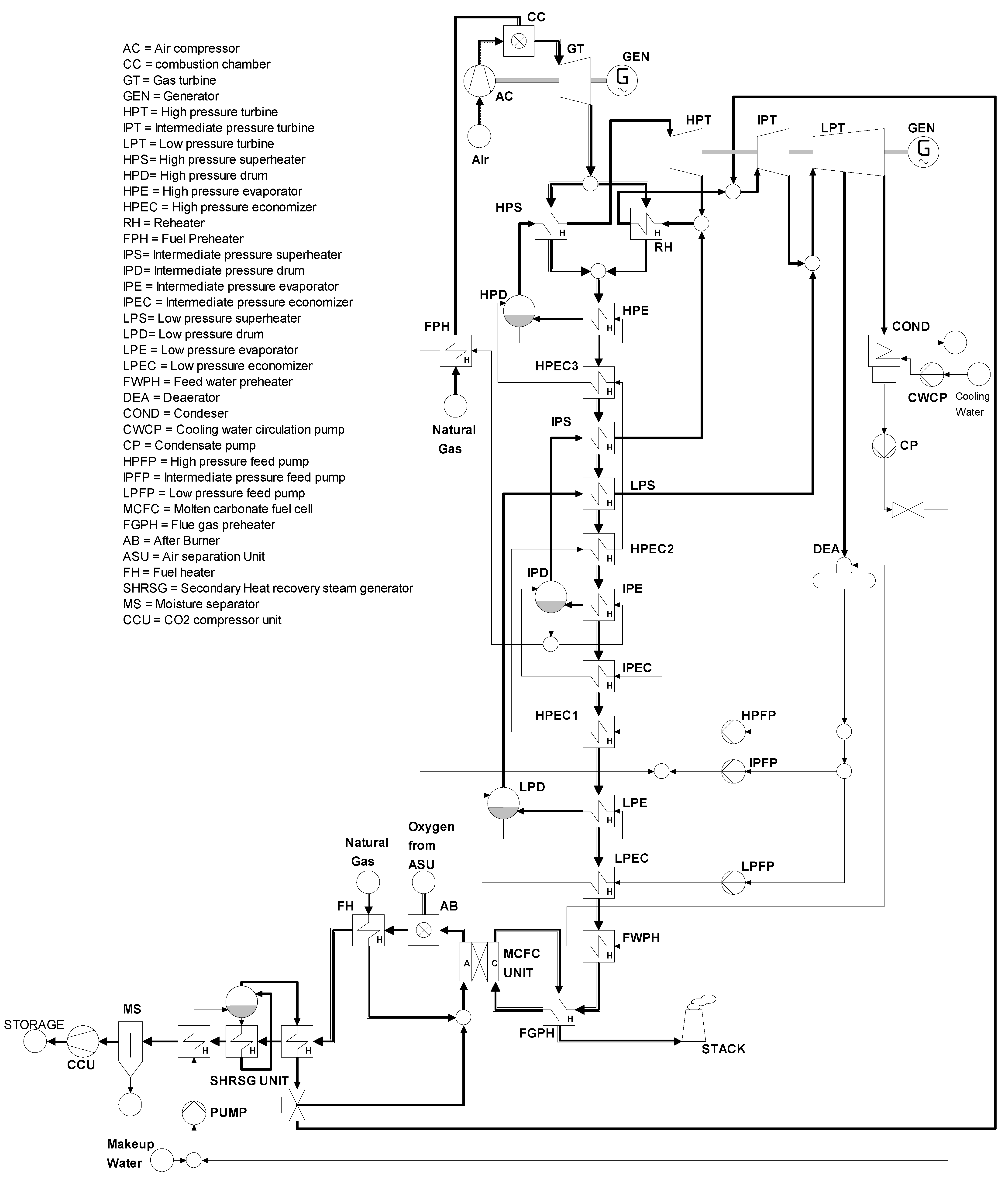
2. Plant Configuration and Modeling
3. Thermodynamic Energy Modeling
3.1. Assumptions
- i.
- The isentropic efficiency values for the turbines, pumps, fans are considered as 88, 86, and 86%, respectively, whereas the generator efficiency has been assumed to be 95% [13].
- ii.
- The molar composition of the natural gas is taken as follows: 89% CH4, 7% C2H6, 1% C3H8, 0.1% C4H10, 2% CO2, 0.89% N2, and the LHV is 46.502 MJ/kg [20].
- iii.
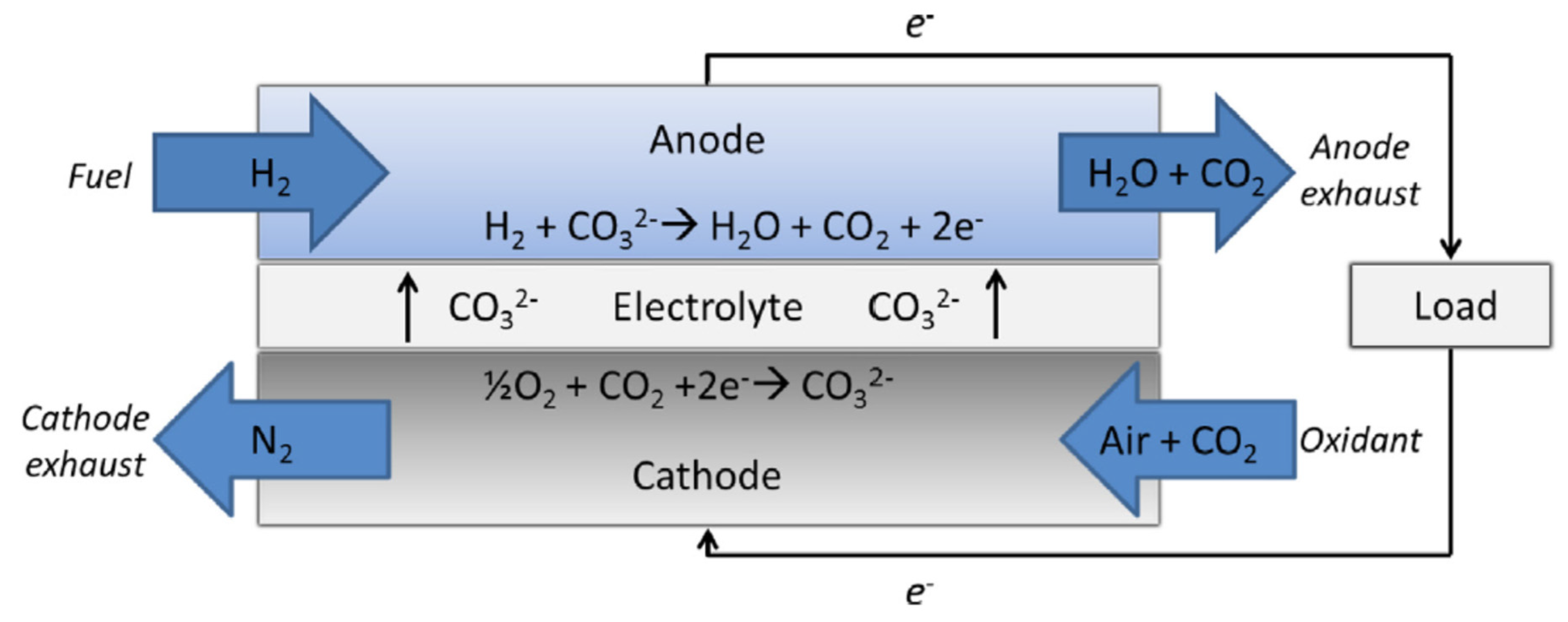
- The fuel utilization factor is taken as 75% and the current density of MCFC is 1000 A/m2. The cell voltage at the nominal condition is 0.7 V, and the MCFC working temperature is set to 650 °C [20].
- iv.
- Steam is added to achieve a steam to carbon ratio of 3.5 in the reforming charge [20].
- v.
- The MCFC unit is isothermal; all the calculated chemical balances and the current density are based on the average cell temperature.
- vi.
- The MCFC stack consists of several identical cells connected in series.
- vii.
- The MCFC acts at near atmospheric pressure.
- viii.
- All processes are analyzed to be steady.
- ix.
- No pressure and heat losses are encountered in any of the state points and components.
- x.
- Atmospheric pressure and temperature are assumed to be 1 atm and 25 °C, respectively.
3.2. Thermodynamic Heat Balance
3.3. Exergy Analysis
4. Results and Discussion
5. Conclusions
Author Contributions
Funding
Institutional Review Board Statement
Informed Consent Statement
Data Availability Statement
Conflicts of Interest
References
- United Nations, Department of Economics and Social Affairs, Population Division. World Urbanization Prospects; The 2018 Revision; United Nations: New York, NY, USA, 2019. [Google Scholar]
- International Energy Agency (IEA). Global Energy Review 2021: Assessing the Effects of Economic Recoveries on Global Energy Demand and CO2 Emissions in 2021; International Energy Agency (IEA): Paris, France, 2021; Available online: https://iea.blob.core.windows.net/assets/d0031107-401d-4a2f-a48b-9eed19457335/GlobalEnergyReview2021.pdf (accessed on 1 October 2021).
- United States Department of Energy. Annual Energy Outlook 2021 with Projections to 2050; U.S. Department of Energy: Washington, DC, USA, 2021.
- Fernandez, E.S.; Goetheer, E.; Manzolini, G.; Macchi, E.; Rezvani, S.; Vlugt, T. Thermodynamic assessment of amine based CO2 capture technologies in power plants based on European Benchmarking Task Force methodology. Fuel 2014, 129, 318–329. [Google Scholar] [CrossRef]
- Discepoli, G.; Cinti, G.; Desideri, U.; Penchini, D.; Proietti, S. Carbon capture with molten carbonate fuel cells: Experimental tests and fuel cell performance assessment. Int. J. Greenh. Gas Control. 2012, 9, 372–384. [Google Scholar] [CrossRef]
- Gatti, M.; Martelli, E.; Di Bona, D.; Gabba, M.; Scaccabarozzi, R.; Spinelli, M.; Viganò, F.; Consonni, S. Preliminary Performance and Cost Evaluation of Four Alternative Technologies for Post-Combustion CO2 Capture in Natural Gas-Fired Power Plants. Energies 2020, 13, 543. [Google Scholar] [CrossRef] [Green Version]
- Campanari, S.; Chiesa, P.; Manzolini, G.; Bedogni, S. Economic analysis of CO2 capture from natural gas combined cycles using Molten Carbonate Fuel Cells. Appl. Energy 2014, 130, 562–573. [Google Scholar] [CrossRef]
- Mamaghani, A.H.; Najafi, B.; Shirazi, A.; Rinaldi, F. Exergetic, economic, and environmental evaluations and multi-objective optimization of a combined molten carbonate fuel cell-gas turbine system. Appl. Therm. Eng. 2015, 77, 1–11. [Google Scholar] [CrossRef]
- Mahmoudi, S.; Ghavimi, A. Thermoeconomic analysis and multi objective optimization of a molten carbonate fuel cell—Supercritical carbon dioxide—Organic Rankin cycle integrated power system using liquefied natural gas as heat sink. Appl. Therm. Eng. 2016, 107, 1219–1232. [Google Scholar] [CrossRef]
- Mei, B.; Qin, Y.; Taghavi, M. Thermodynamic performance of a new hybrid system based on concentrating solar system, molten carbonate fuel cell and organic Rankine cycle with CO2 capturing analysis. Process. Saf. Environ. Prot. 2021, 146, 531–551. [Google Scholar] [CrossRef]
- Akrami, E.; Ameri, M.; Rocco, M.V. Developing an Innovative biomass-based Power Plant for low-carbon Power production: Exergy and Exergoeconomic analyses. Therm. Sci. Eng. Prog. 2020, 19, 100662. [Google Scholar] [CrossRef]
- Spallina, V.; Romano, M.C.; Campanari, S.; Lozza, G. Application of MCFC in Coal Gasification Plants for High Efficiency CO2 Capture. J. Eng. Gas Turbines Power 2011, 134, 011701. [Google Scholar] [CrossRef]
- Samanta, S.; Ghosh, S. A thermo-economic analysis of repowering of a 250 MW coal fired power plant through integration of Molten Carbonate Fuel Cell with carbon capture. Int. J. Greenh. Gas Control. 2016, 51, 48–55. [Google Scholar] [CrossRef]
- Li, M.; Zhuang, Y.; Song, M.; Li, W.; Du, J. Techno-economic and carbon footprint feasibility assessment for polygeneration process of carbon-capture coal-to-methanol/power and molten carbonate fuel cell. Energy Convers. Manag. 2021, 235, 114015. [Google Scholar] [CrossRef]
- Spinelli, M.; Campanari, S.; Consonni, S.; Romano, M.C.; Kreutz, T.; Ghezel-Ayagh, H.; Jolly, S. Molten Carbonate Fuel Cells for Retrofitting Postcombustion CO2 Capture in Coal and Natural Gas Power Plants. J. Electrochem. Energy Convers. Storage 2018, 15, 031001. [Google Scholar] [CrossRef]
- Slater, J.; Chronopoulos, T.; Panesar, R.; Fitzgerald, F.; Garcia, M. Review and techno-economic assessment of fuel cell technologies with CO2 capture. Int. J. Greenh. Gas Control. 2019, 91, 102818. [Google Scholar] [CrossRef]
- Mehrpooya, M.; Sayyad, S.; Zonouz, M.J. Energy, exergy and sensitivity analyses of a hybrid combined cooling, heating and power (CCHP) plant with molten carbonate fuel cell (MCFC) and Stirling engine. J. Clean. Prod. 2017, 148, 283–294. [Google Scholar] [CrossRef]
- Ansarinasab, H.; Mehrpooya, M. Investigation of a combined molten carbonate fuel cell, gas turbine and Stirling engine combined cooling heating and power (CCHP) process by exergy cost sensitivity analysis. Energy Convers. Manag. 2018, 165, 291–303. [Google Scholar] [CrossRef]
- Campanari, S.; Chiesa, P.; Manzolini, G.; Giannotti, A.; Federici, F.; Bedont, P.; Parodi, F. Application of MCFCs for active CO2 capture within natural gas combined cycles. Energy Procedia 2011, 4, 1235–1242. [Google Scholar] [CrossRef] [Green Version]
- Campanari, S.; Chiesa, P.; Manzolini, G. CO2 capture from combined cycles integrated with Molten Carbonate Fuel Cells. Int. J. Greenh. Gas Control. 2010, 4, 441–451. [Google Scholar] [CrossRef]
- Carapellucci, R.; Saia, R.; Giordano, L. Study of Gas-steam Combined Cycle Power Plants Integrated with MCFC for Carbon Dioxide Capture. Energy Procedia 2014, 45, 1155–1164. [Google Scholar] [CrossRef] [Green Version]
- Manzolini, G.; Campanari, S.; Chiesa, P.; Giannotti, A.; Bedont, P.; Parodi, F. CO2 Separation from Combined Cycles Using Molten Carbonate Fuel Cells. J. Fuel Cell Sci. Technol. 2011, 9, 011018. [Google Scholar] [CrossRef]
- Carapellucci, R.; Cipollone, R.; Di Battista, D. MCFC-Based System for Active CO2 Capture from Flue Gases. In ASME International Mechanical Engineering Congress and Exposition; Volume 6A: Energy; American Society of Mechanical Engineers: Pittsburgh, PA, USA, 2018. [Google Scholar]
- Barelli, L.; Bidini, G.; Campanari, S.; Discepoli, G.; Spinelli, M. Performance assessment of natural gas and biogas fueled molten carbonate fuel cells in carbon capture configuration. J. Power Sources 2016, 320, 332–342. [Google Scholar] [CrossRef]
- Cycle-Tempo Software Version 5; Asimptote: Heeswijk Dinther, The Netherlands; Available online: http://www.asimptote.nl/software/cycle-tempo/ (accessed on 1 October 2021).
- Rexed, I.; della Pietra, M.; McPhail, S.J.; Lindbergh, G.; Lagergren, C. Molten carbonate fuel cells for CO2 separation and segregation by retrofitting existing plants—An analysis of feasible operating windows and first experimental findings. Int. J. Greenh. Gas Control. 2015, 35, 120–130. [Google Scholar] [CrossRef]


| Parameters | Present Study | Reference Study [4] |
|---|---|---|
| Airflow in Gas turbine Unit (kg/s) | 1299.97 | 1300 |
| Fuel flow in Gas turbine Unit (kg/s) | 30.6 | 30.6 |
| Gas flow at Gas turbine inlet (kg/s) | 1330.57 | 1330.6 |
| Gas turbine inlet temperature (°C) | 1268 | 1265.7 |
| Gas turbine outlet temperature (°C) | 608 | 608 |
| HP steam flow rate (kg/s) | 152.89 | 153.7 |
| HP steam pressure (bar) | 121 | 120.9 |
| HP steam temperature (bar) | 559.5 | 559.5 |
| IP steam flow rate (kg/s) | 183.48 | 185 |
| IP steam pressure (bar) | 23 | 22.96 |
| IP steam temperature (bar) | 561 | 561 |
| Gas turbine unit output (MW) | 544.39 | 544.24 |
| Steam turbine unit output (MW) | 291.05 | 292.78 |
| Parameters | Values |
|---|---|
| Gross power output (MW) | 833.438 |
| Auxiliary power consumption (MW) | 3.461 |
| Net Power Output (MW) | 829.797 |
| Thermal input energy (MW) | 1422.9 |
| Net Plant efficiency (%) | 58.317 |
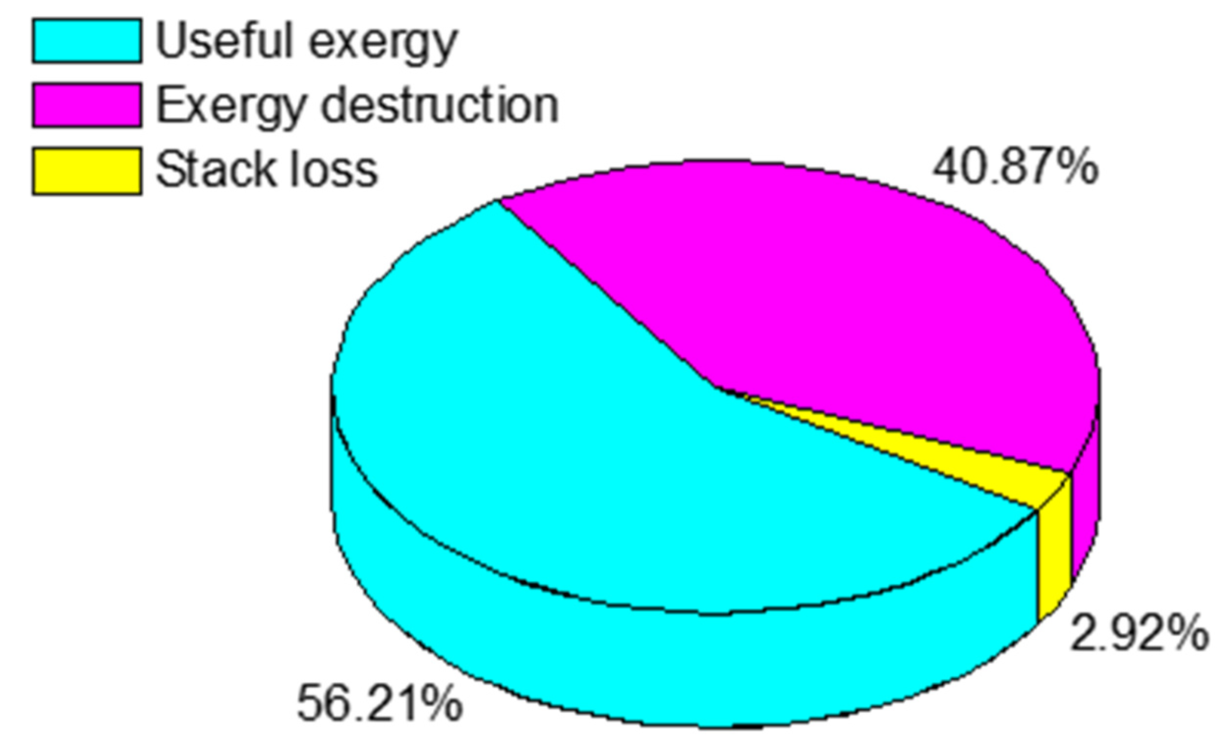
| Net exergy efficiency (%) | 56.212 |
| Specific CO2 emission (kg/MWh) | 416.5 |
| Parameters | Values |
|---|---|
| Gas turbine output (MW) | 435.29 |
| Steam cycle output (MW) | 248.9 |
| Fuel cell output (MW) | 135.283 |
| Auxiliary power consumption (MW) | 28.415 |
| Power consumption by ASU (MW) | 3.604 |
| Net Power Output (MW) | 787.454 |
| Input energy in combined-cycle plant (MW) | 1138.32 |
| Input energy in Fuel cell Unit (MW) | 284.58 |
| Total input energy into the integrated plant (MW) | 1422.9 |
| Net Plant efficiency (%) | 55.34 |
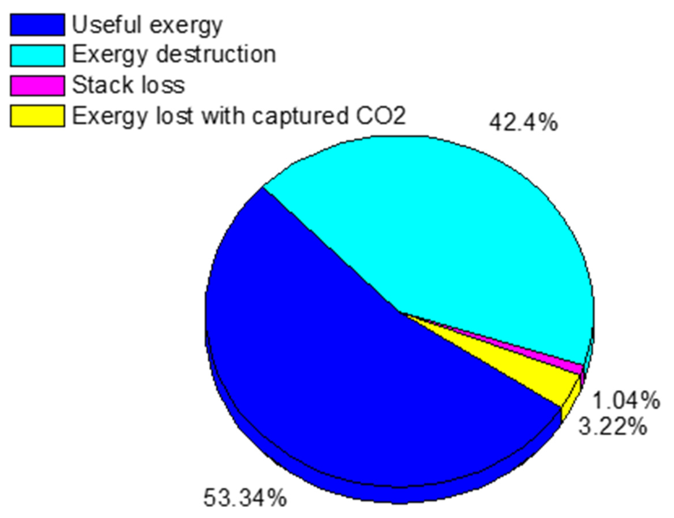
| Net exergy efficiency (%) | 53.34 |
| Specific CO2 emission (kg/MWh) | 66.67 |
| Total annual CO2 sequestrated (ton/year) | 1.991 × 10⁶ |
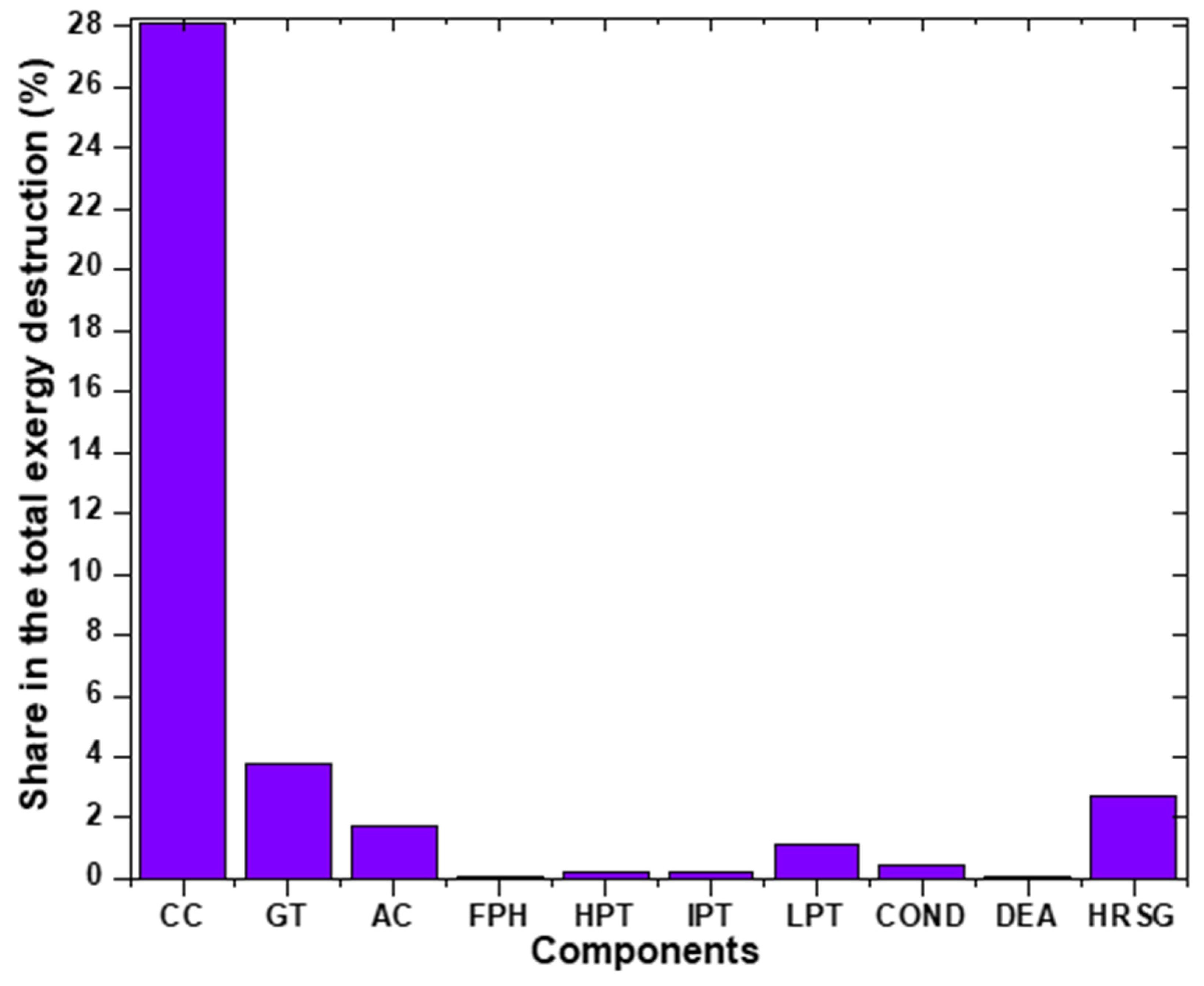
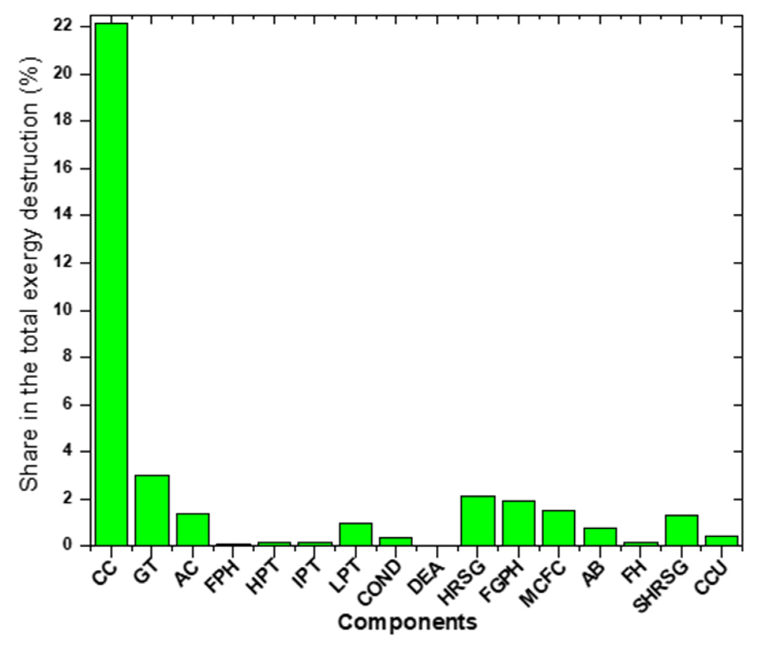
| Sl.no. | Name of the Component | Amount of Exergy Destructed | Unit | |
|---|---|---|---|---|
| Existing Plant | Repowered Plant | |||
| 1 | AC | 25,622.66 | 20,498.12 | kW |
| 2 | CC | 418,049.22 | 334,420.62 | kW |
| 3 | GT | 56,355.88 | 45,084.69 | kW |
| 4 | FPH | 1257.12 | 1005.69 | kW |
| 5 | HRSG | 38,197.27 | 30,575.74 | kW |
| 6 | HPT | 3024.81 | 2419.43 | kW |
| 7 | IPT | 3334.95 | 2943.77 | kW |
| 8 | LPT | 16,344.15 | 14,338.22 | kW |
| 9 | COND | 6065.63 | 5224.94 | kW |
| 10 | CWCP | 229.18 | 203.47 | kW |
| 11 | CP | 12.21 | 10.90 | kW |
| 12 | DEA | 716.37 | 537.37 | kW |
| 13 | HPFP | 476.68 | 382.49 | kW |
| 14 | IPFP | 20.59 | 17.90 | kW |
| 15 | LPFP | 2.09 | 1.75 | kW |
| 16 | STACK | 43,439.18 | 38,842.80 | kW |
| 17 | FGPH | - | 28,721.55 | kW |
| 18 | MCFC stack | - | 23,312.55 | kW |
| 19 | AB | - | 11,441.98 | kW |
| 20 | FH | - | 2804.30 | kW |
| 21 | SHRSG | - | 20,203.12 | kW |
| 22 | PUMP | - | 14.98 | kW |
| 23 | MS | - | 5100.95 | kW |
| 24 | CCU | - | 4145.41 | kW |
Publisher’s Note: MDPI stays neutral with regard to jurisdictional claims in published maps and institutional affiliations. |
© 2022 by the authors. Licensee MDPI, Basel, Switzerland. This article is an open access article distributed under the terms and conditions of the Creative Commons Attribution (CC BY) license (https://creativecommons.org/licenses/by/4.0/).
Share and Cite
Fichera, A.; Samanta, S.; Volpe, R. Exergetic Analysis of a Natural Gas Combined-Cycle Power Plant with a Molten Carbonate Fuel Cell for Carbon Capture. Sustainability 2022, 14, 533. https://doi.org/10.3390/su14010533
Fichera A, Samanta S, Volpe R. Exergetic Analysis of a Natural Gas Combined-Cycle Power Plant with a Molten Carbonate Fuel Cell for Carbon Capture. Sustainability. 2022; 14(1):533. https://doi.org/10.3390/su14010533
Chicago/Turabian StyleFichera, Alberto, Samiran Samanta, and Rosaria Volpe. 2022. "Exergetic Analysis of a Natural Gas Combined-Cycle Power Plant with a Molten Carbonate Fuel Cell for Carbon Capture" Sustainability 14, no. 1: 533. https://doi.org/10.3390/su14010533