Article

Manufacturing of Low-Carbon Binders Using Waste Glass and Dredged Sediments: Formulation and Performance Assessment at Laboratory Scale

by
Abdelhadi Bouchikhi
1,2,*,
Walid Maherzi
1,2,
Mahfoud Benzerzour
1,2,
Yannick Mamindy-Pajany
1,2,
Arne Peys
3 and
Nor-Edine Abriak
1,2
1
Laboratoire de Génie Civil et Géo-Environnement (LGCgE), Université Lille-1, 59000 Lille, France
2
Institut Mines-Télécom, (IMT)-Lille-Douai, 59500 Douai, France
3
Sustainable Materials, Vlaamse Instelling voor Technologisch Onderzoek (VITO), Boeretang 200, 2400 Mol, Belgium
*
Author to whom correspondence should be addressed.
Sustainability 2021, 13(9), 4960; https://doi.org/10.3390/su13094960
Submission received: 31 March 2021 / Revised: 24 April 2021 / Accepted: 26 April 2021 / Published: 28 April 2021
(This article belongs to the Special Issue Innovative Construction Materials for Sustainable Development)

Abstract

:
Few studies focus on the co-valorization of river dredging sediments (DS) and residual waste glass (RWG) in alkali-activated binders. This study investigates the use of DS as an aluminosilicate source by substituting a natural resource (metakaolin (MK)), while using RWG as an activator (sodium silicate source). Suitable treatments are selected to increase the potential reactivity of each residue. The DS is thermally treated at 750 °C to promote limestone and aluminosilicate clays’ activation. The RWG (amorphous, rich in silicon, and containing sodium) is used as an alkaline activator after treatment in 10 M NaOH. Structural monitoring using nuclear magnetic resonance (29NMR and 27NMR), X-ray diffraction, and leaching is conducted to achieve processing optimization. In the second stage, mortars were prepared and characterized by determining compressive strength, water absorption, mercury porosimetry and Scanning Electron Microscopy with Energy Dispersive Spectroscopy (SEM-EDS). Results obtained show the great advantage of combining RWG and DS in an alkali-activation binder. The treated RWG offers advantages when used as sodium silicate activating solution, while the substitution of MK by calcined sediments (DS-750 °C) at 10%, 20%, and 30% leads to improvements in the properties of the matrix such as an increase in compressive strength and a refinement and reduction of the pore size within the matrix.

1. Introduction

Global warming and overexploitation of natural resources are concerning issues for the future. To preserve the planet, it is necessary to minimize these phenomena urgently by partially or completely replacing polluting industries by more ecological alternatives (e.g., industries that use renewable energy and/or recycle solid waste). Several studies focus on the insertion of different types of solid waste into construction materials (such as sediments, fly ash, glass, bottom ash, silica fume, and slag) and on the reduction in the quantity of cement. Simultaneously, ecological binders such as geopolymers and alkali-activated materials (which do not have the same hardening mechanism as Portland binders) have received increasing interest.
The term geopolymers was coined by Davidovits (1978) [1] and refers to inorganic polymers with an aluminosilicate backbone. These polymers are produced from an aluminosilicate source (e.g., metakaolin (MK), and fly ash) [2] which reacts with an alkali silicate solution (e.g., sodium or potassium silicate) to form a Na/K-aluminosilicate network. Some studies refer to these polymers as polysialate [1] and (N/K)-A-S-H type gel [3]. The geo-polymerization of aluminosilicates occurs in three essential stages: dissolution, reorganization and polycondensation [3]. These steps are influenced by the reactivity of aluminosilicates in the solution. Several studies deal with the release rate or leaching behavior of Al and Si, which are included within the network formers of the geopolymer and the main participants in the abovementioned reactions. The leaching rate of these elements is influenced by the alkalinity of the activator, processing temperature, and particle size of the aluminosilicate precursor. The degree of crystallization and structure of the amorphous fraction of the aluminosilicate precursor affects the dissolution mechanism and rate of Al and Si [4]. Lee and van Deventer [5] leached fly ash at 20 °C in low and high alkaline solutions. Ca and Si are the first elements extracted, followed by Al in low alkaline media. Hajimohammadi et al. [6] investigated the mechanism of dissolution and the nucleation of aluminosilicate particles. They explained that the dissolution of Al is easier compared to the dissolution of Si. These dissolved species reorganize and polymerize to form a gel, and they ultimately form a solid network [7,8,9].
Contact time with the leaching medium and liquid/solid ratio influenced the dissolution of Si and Al. Among the most studied methods, Bian et al. [10] (based on that of Chen-Tan [4]) consists of treating 5 g of glass powder (dmax > 45 µm) in an alkaline −10 M with a liquid/solid ratio of 10. However, the reaction time and liquid–solid ratio cannot be varied as freely as that in real samples.
With its chemical composition (70–72% SiO2, 12–14% CaO, 1–3% Al2O3, 9–12% Na2O) and amorphous structure, waste glass can be used as pozzolan in blended cements [11] and in geopolymers or alkali-activation binders as activator or silicate precursor [9,10,12,13]. Torres-Carrasco et al. suggested a method to dissolve glass powder in 10 M sodium hydroxide at 80 °C for 6 h [12]. After activation, the glass solution was used as a sodium silicate activator. Several studies investigated the activation of glass and siliceous compounds, such as silica fumes, via alkaline attack with the aim of using them as activators that can replace the commercial sodium silicate solution, which is an expensive and CO2 intensive product (Torres-Carrasco and Puertas, 2015) [9,12,13,14]. In all these studies, the dissolution of a silicate system is linked to parameters similar to those mentioned above for the dissolution of the aluminosilicate precursor for geo-polymerization (particle size, temperature, alkalinity, and contact time). The dissolution of the glass remains linked to the processing temperature, which can be explained by Arrhenius’s law [15].
Dredging sediments (DS) are one of the main wastes generated by marine and river activities. This is necessary to ensure the smooth functioning of waterways [16]; further, the management of this waste must comply with certain regulations. The key parameters include their classification in terms of pollution, such as metalloids and metallic trace elements (MMTE) and anions such as Cl, F, and SO42−. Similarly, the required storage space for these sediments is very large because of the large quantities of dredging estimated at 300 million m3/year in Europe and around 56 million m3/year in France. Several studies have already been carried out on the valorization of DS as supplementary cementitious material (SCM) to substitute for the natural resources in cement [17,18,19].
The sediments are composed of common mineral phases (such as clays, calcite, quartz, and feldspars), and also contain organic materials (varying between 7%–30% depending on the nature of the sediments) that demand treatment before they can be employed in applications. Calcination, a heat treatment over a temperature range between 600 and 800 °C, can be used to obtain a partially amorphous (calcium) aluminosilicate precursor and decompose the organic material [20,21]. If the material is heated to very high temperatures (>900 °C), recrystallization can occur, which can result in decreased reactivity.
This paper combines the activation of residual waste glass (RWG) and DS to create an alkali-activation binder. A sodium silicate activating solution was obtained by optimizing the dissolution of RWG in NaOH. The DS was optimized as a calcium-aluminosilicate source by calcination. These two optimal components are used in the mix design of geopolymer binders. The proposed formulations were studied from the point of view of mechanical properties and environmental performance by compressive strength measurements, mercury intrusion porosimetry, leaching of MMTEs, and anionic species Cl, F, and SO42− following French directive No.0289 published in 2014.

2. Materials and Methods

2.1. Methods

The specific surface area (SSA) of the studied powders was calculated from nitrogen sorption experiments using an AGITENT Analyzer (Micromeritics 3FLEX Surface Characterization) and Brunauer–Emmett–Teller (BET) calculations according to [22]. A smart prep degasser (VacPrep 061) was used before analyzing the powders to remove adsorbed contaminants and humidity. The specific density was determined according to the standard [23], using a Micromeritics ACCUPYC 1330 Helium Pycnometer device. Particle size distributions were obtained by laser diffraction using a Coulter LS12330 apparatus (ISO 13320-1). Mercury intrusion porosimetry was performed in a Micromeritics AUTOPORE IV [24]. Microscopic images were obtained using a scanning electron microscope (SEM, type Hitachi S-4300SE/N). Local chemical energy dispersive X-ray spectrometry (EDS) analyses were performed with a Thermo Scientific Ultra Dry EDS detector.
The overall chemistry was investigated using X-ray fluorescence (XRF) analysis on a S4-PIONEER equipped with a 4-kW generator and Rh anode. X-ray diffraction (XRD) was used for mineralogical analyses using a D8 Focus diffractometer from Bruker with a cobalt anode (λKα1 = 1.74 Ǻ) equipped with a Lynx Eye detector. The measurement range was 5 to 80° 2θ, and a step size of 0.02° and time step of 1s was used. A divergence slit of 0.2 mm was used, and 40 kV and 30 mA were used to perform the measurements. 29Si magic-angle spinning nuclear magnetic resonance (NMR) spectra were obtained with a Bruker Avance 400 MHz (9.4 T) at a Larmor frequency of 79.5 MHz at a magic-angle of 54.7° and at spin rates of 5kHz in zirconia rotors with an outer diameter of 7 mm; tetramethyl silane was used as a reference. The spectrum of the RWG 1152 scans was recorded with a pulse length of 5 μs (π/2) and a relaxation delay of 60 s. The treated waste glass (TWG) spectrum was obtained from 1024 scans with a pulse length of 5 μs (π/2) and a relaxation delay of 10 s. The deconvolution of the spectra was performed with DMF software [21]. Thermal analysis was performed using a QMS 403D-NETZSCH machine; for thermogravimetric analysis, the gas used is argon with a beginning of 20mL/min. Differential scanning calorimetry and mass spectrometry were used for the gas analyses of the volatile decomposition products. The gas analyzed in this study was H2O, CO, CO2, and SO3. The pH and electrical conductivity were measured using CONSORT C832. The temperature during the measurement was 22 °C and the values were measured after stabilization.
Mortar specimens were leached to evaluate the mobility of MMTE after filtering. The leachates were measured with an inductively coupled plasma atomic emission spectrometer (ICP-AES) with an Agilent Technologies SPS4 Autosampler. Compressive strength was measured on 4 × 4 × 16 cm3 prisms in accordance with the standard [25] after 7 days at 60 °C. In a previous study, Bouchikhi et al. [26] showed that the mechanical strengths of mortars do not change shortly after 7 days of cure at 60 °C. A 15 ton INSTRON press was used with a load speed of 144 kN/min.
The mobility of MMTE and major elements in the RWG treated and the DS (raw and calcined) were measured after specimen leaching using a liquid–solid ratio of 10 L/kg and by using an equilibrium time of 24 h, according to [27]. Leachates were filtered at 0.45 µm and acidified with 2% (v/v) HNO3 commercial solution (63% by weight) before performing chemical analyses using an inductively coupled plasma optical emission spectrometer (ICP-OES 5100 Agilent Technologies). Anionic elements were analyzed by chromatography and without acidification. The detection limit for the ICP-AES is presented in each element (mg/kg). The leaching limit values of inert waste (IW) and nonhazardous waste (NHW) given by Directive 1999/31/EC on the landfill of waste were used to verify the conformity of materials.

2.2. Materials

The studied RWG was collected from the Prover recycling manufacture (in Wingles, France), which specializes in collecting and recycling waste glass. The DS is fluvial sediment from the territorial management of Château d’Abbaye, supplied by the Navigable Waterways of France (Voies Navigables de France (VNF)). The DS were dried in an oven (40 °C) and then ground with dmax = 120 µm (complete particle size distribution in Figure 1). The alkaline solution was prepared in advance by dissolving NaOH pellets (purity 98.8%) in demineralized water. The sand used for producing 4 × 4 × 16 cm3 mortars is certified in accordance with the standard CEN 196-1 ISO. The particle size distribution was determined by sieving in accordance with the requirements of standard EN 196-1. The resulting characteristic diameters are d90 = 0.08–2 mm and d50 = 0.9mm. MK is used as an aluminosilicate source supplied by ARGECO and characterized by particle size d50 = 6.7 µm and d90 = 22.8 µm.

2.2.1. Physical and Chemical Characterization

The physicochemical characteristics (Table 1) showed considerable loss on ignition for the DS of approximately 10.4, 11.2, and 12.5 wt% for treatments at 450 °C/3 h, 550 °C/1 h, and 1000 °C/1 h. RWG and MK only presented low mass losses.
The elemental chemical and oxides compositions of RWG, DS, and MK are presented in Table 2 and Table 3, respectively. The DS is composed of 58 wt% SiO2, 12 wt% Al2O3, 7 wt% Fe2O3, and 8 wt% CaO with low contents of MgO, P2O5, SO3, TiO2 and Na2O. This chemical composition of DS is linked to the nature of the soil in the Haut de France region. The MK aluminosilicate source contains 74 wt% SiO2 and 22 wt% Al2O3 with low contents of MgO, CaO, and TiO2. The RWG is composed of 71 wt% SiO2, 1 wt% Al2O3, 14 wt% CaO, 13 wt% Na2O and 1 wt% MgO, with the presence of other elements in low quantity, which can play a role in the color and rheology of the glass (such as Fe2O3 and Cr2O3).

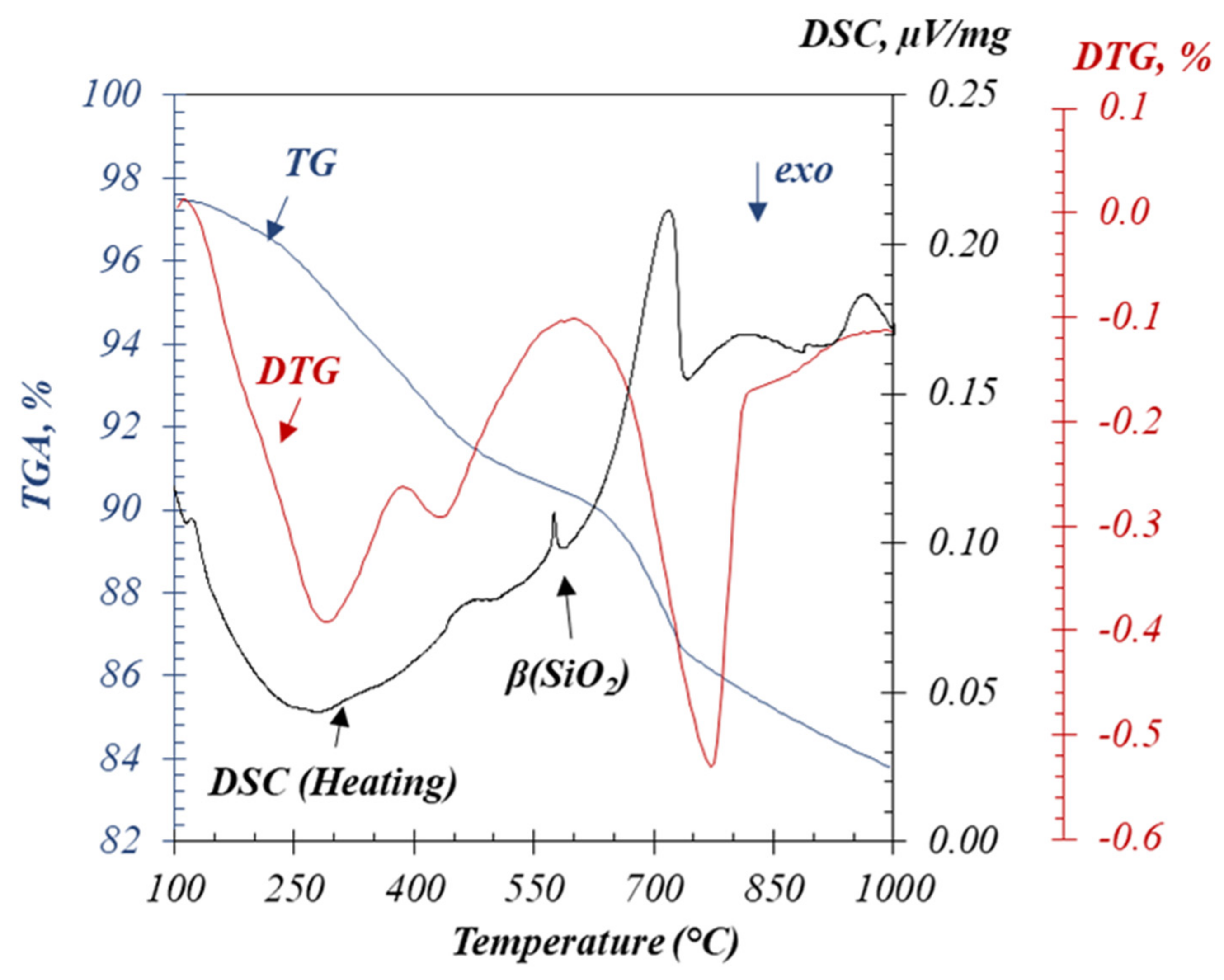
2.2.2. Thermal Treatment of Sediments

To choose the optimal calcination temperature for the DS, the thermal behavior is assessed using TGA-DSC (Figure 2) and TGA-MS (Figure 3). Up to 450 °C, a mass loss of 6 wt% was observed. Figure 3 shows that mainly H2O evolves from the DS at this temperature interval. More specifically, in the DTG 2, peaks and a shoulder are observed and four peaks are observed in the intensity of the water band (Figure 3). It is probable that these peaks (range of 120–450 °C) correspond to the evaporation of adsorbed water (a,b), the decomposition of hydroxides such as FeO-OH (b), and the de-hydroxylation of kaolinite and illite (c) [28,29]. Montmorillonite exhibits a removal of the OH groups (de-hydroxylation) at higher temperatures, which can be observed in the range 400–800 °C, with a slow release of water up to 800 °C (d) [30]. Another 6% mass loss, which is endothermic, is observed because of a strong release of CO and CO2. The decarbonation of limestone (calcium carbonate) occurs at this temperature interval. At 750 °C, the main calcination reactions were completed, especially for majority phase limestone and dihydroxylation of clay. At higher temperatures, pozzolanic activity was more likely to decrease because of recrystallization [31]. Accordingly, 750 °C was selected as the maximum temperature to achieve the complete decomposition of clay minerals and calcium carbonates and to optimize the reactivity of the DS.

2.2.3. Activation of Residual Waste Glass

According to Bouchikhi et al. [26], 30 g of RWG was dissolved in 100 mL of a 10M NaOH solution in the optimized method; the treatment temperature was 85 °C for 4 h then drying occurred for 24 h at 120 °C. The optimized amount of RWG/NaOH provided a balance, avoiding the supersaturation of the medium, thereby resulting in untreated glass aggregates and avoiding under saturation. This resulted in unreacted NaOH and a lower molar ratio of silicate to NaOH (lower n(SiO2)/n(NaOH)). In this study, the importance of this optimized pretreatment is underlined by theoretical considerations based on Figure 4. To assess the reactivity of silicate glass, it is necessary to determine the relationship between the bridge oxygens (BO) in the RWG and the quantity of NaOH required to obtain a maximum of non-bridging oxygens (NBO). The starting point for RWG is a silicate network with an average connectivity Qn = 3.2; this is a considerably stable structure (Figure 4). A lower connectivity (higher number of NBO) is required to achieve sufficient reactivity as an alkaline activator, because a higher number of NBO results in a more reactive silicate structure. According to research conducted on glass structures (SiO2 > 50%) [32,33], it is possible to establish a relationship between the molar ratio n(SiO2)/n(NaOH) and the degree of connectivity of silicon (and the amount of NBO and BO)
y = 6 200 p
where p and y denote the molar percentage of silicon and the percentage of bridging oxygen in the glass structure, respectively. The number of NaOH moles necessary for the dissolution of 1 M of silicon (1.n(SiO2)) in the structure of RWG is determined according to:
1 . n SiO 2 = 1   y n . SiO 2 Q 4 +   y n . SiO 2 Q 3   = 1   y n . SiO 2 Q 4 +   y n , SiO 2 Q 3 = 1   y n . n NaOH 4 + y n . n NaOH 3 = n NaOH 1   y n 4 +   y n 3 = n NaOH . 3 + y n 12
n SiO 2   / n NaOH = 3 + y n 12
The ratio n(SiO2)/n(NaOH) in the optimized treated RWG (TRWG) was calculated to be 0.26.

3. Results and Discussion

3.1. Optimization of Sediment Calcination Temperature

3.1.1. XRD Analysis

The evolution of the phase composition from the DS to the CS (450–950 °C) was determined using XRD (Figure 5). The interpretation of the diffractogram shows that the raw sediment consists of quartz, calcite, and aluminosilicate minerals (kaolinite (14°, 48° and 49° 2θ), illite (10° 2θ), Smectite (7° 2θ, and feldspath (23°, 27° and 28° 2θ). These primary mineralogical phases identified (especially in DS) are coherent with the nature of the geologic platform for the Hauts-de-France region. The calcination results show a total degradation of the characteristic peak of CaCO3 (30.1° 2θ) after calcination at temperatures higher than or equal to 750 °C and the apparent characteristic peaks of free lime (14° and 32° 2θ) [34]. This total loss is caused by the decarbonization of limestone to form free lime (38° 2θ), which in its turn may interact with the aluminosilicate phases to form Ca-feldspar at 850–950 °C [30,35]. The peaks characteristic of hematite (25°, 34° and 38° 2θ) have been detected in the sediments calcined between 750 °C and 850 °C. According to the chemical nature of this material, it is possible that other phases are present but difficult to detect under the effect of strong crystallinity and the strong presence of quartz.

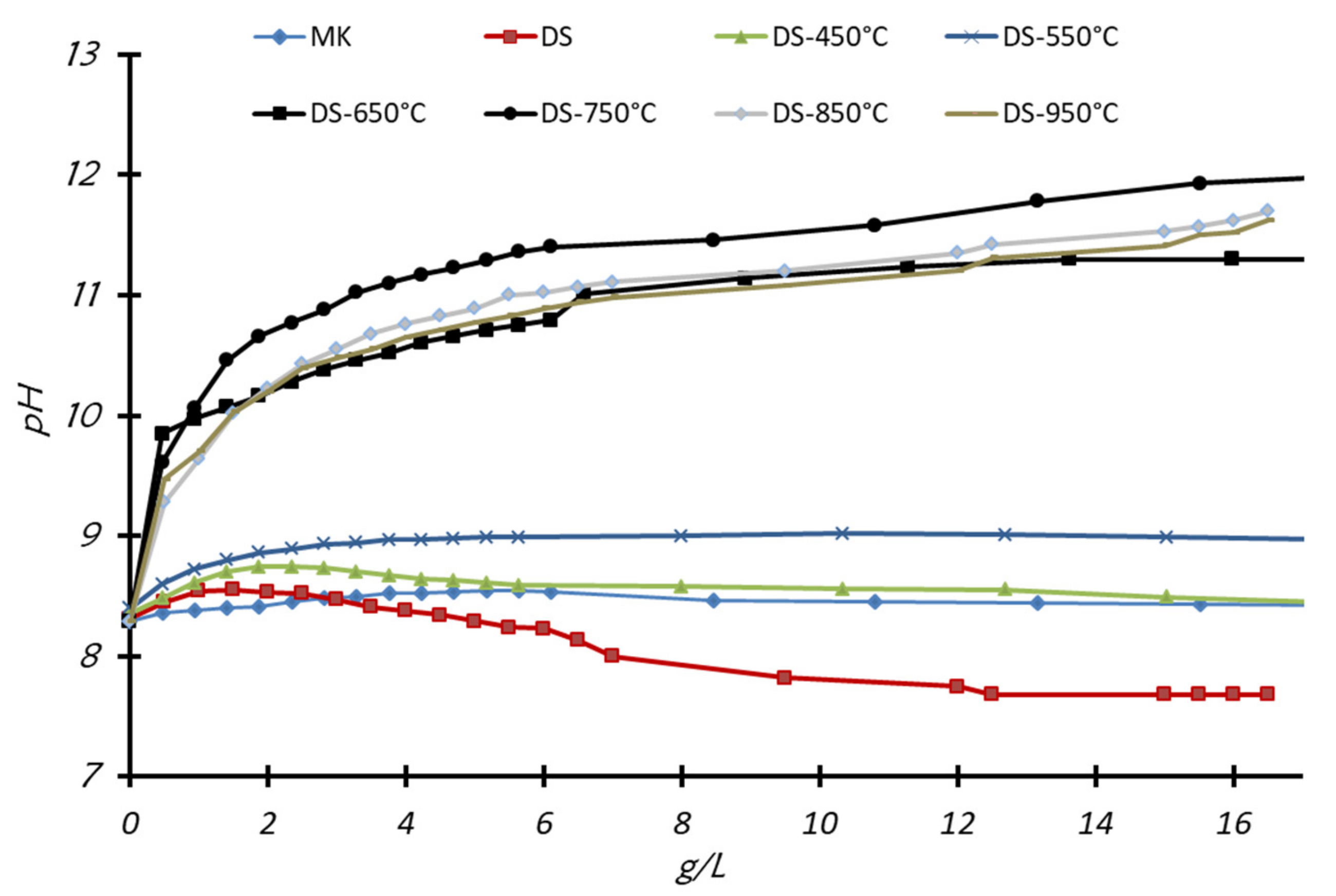
3.1.2. Evolution of Physico-Chemical Properties with Calcination of DS

The change in the reactivity of the DS with calcination temperature was assessed by measuring the pH and electrical conductivity after mixing the (calcined) sediment with water in different concentrations. As such, the rapid monitoring of the dissolution of species from the sediment is provided. Measurements were carried out on dredged (dried at 120 °C) and calcined sediments (CS), treated at 450 °C, 550 °C, 650 °C, 750 °C, 850 °C and 950 °C. The results are presented in Figure 6 (pH) and Figure 7 (electrical conductivity). For dried DS, the pH of the suspension remained around 8, while a slight increase was observed for calcinations at 450 °C and 550 °C with a value below 9. For CS at 650 °C and 750 °C, a remarkable increase in pH was observed with the value reaching 12.2 at 16 g/L. Similarly, the conductivity of the solution remained low for the DS and the sediments calcined at 450 °C and 550 °C, with a value of approximately 150 mS/cm2 for a concentration of 20 mg/L against 350 mS/cm2 for sediments calcined at 750 °C for the same concentration. The increases in pH and ionic conductivity in solution at 750 °C are linked to the decarbonation of limestone to CaO between 650 and 750 °C [36] (compatible with TG analysis). Decarbonation facilitates the solubility of calcium. Most probably, after increasing the pH by dissolving CaO, the activated clay minerals start dissolving more rapidly. Calcination at high temperatures (850 °C and 950 °C) does not promote the pH in the medium. A decrease in pH was observed compared to that at 750 °C.
The availability of major elements (Si, Al, Na, K, Ca and Mg) favors the solidification of the alkali-activated matrix [37]. Figure 8 presents the evolution of the leaching behavior of the elements in mmol/kg, and the evolution of physical properties, the SSA and absolute density was measured. The dissolution was conducted at solid–liquid (L/S) ratios of 10 for 24 h. The results show a significant mobility of Ca2+after calcination at 750 °C (290 mmol/kg), which decreases at higher calcinations to 240 mmol/kg and 220 mmol/kg, respectively, at 850 °C and 950 °C. For calcinations at a temperature lower than 750 °C, the release is markedly lower, which does not exceed 120 mmol/kg (precisely at 450 °C). The evolution of the release of other elements decreases as a function of temperature. The alkalis (Na+ and K+) are very reactive even after calcination at low temperatures (from 450 °C). A low concentration of Si and Al was observed at all calcination temperatures. Changes in the physical properties (SSA and density) of calcined DS show (non-critical) decreases in SSA up to 720 °C, followed by a critical decrease between 720 °C and 950 °C. The density increases with an interesting slope from 750 °C, which shows the phenomena of sintering and changes in the structure of the clays. All observations of the mobility of the major elements and the evolution of physical properties support the hypothesis that the clay sheets present in the sediments undergo collapse from the critical point at around 720 °C. The need to go through the CaCO3 decarbonation zone requires an increase in the calcination temperature to 750 °C.
The pH and electrical conductivity (Ec) measured for DS and calcined DS using an L/S = 10, using an equilibrium time of 24 h (as opposed to 5 min in Figure 6 and Figure 7), were also studied (Table 4). Calcination at high temperatures (850 °C and 950 °C) did not promote the pH and Ec; on the contrary, a decrease in these two factors was observed. This observation can be explained by reactions that can occur at high temperatures between the phases present to form stable or nonreactive crystalline phases and the participation of the foundation of the clay structure [38]. Further, calcination at 750 °C has been the focus of other studies on clays and clay phase matrices [28].

3.1.3. Structural Evolution of 29Si by NMR Analysis

The 29Si-NMR chemical shift spectra of DS, DS-750 °C and MK are shown in Figure 9. These results show that calcination at 750 °C does not lead to drastic changes in the degrees of connectivity of 29Si compared to DS. Slight modifications were observed, which can be attributed to the degradation of clay-humic complexes and the de-hydroxylation of clay minerals. The partial incorporation of Ca in the amorphous silicate phase can also lower the connectivity of the silicate network and as such can modify the NMR spectrum as observed. In MK, DS and DS-750 °C, the chemical shifts of 29Si around −110 ppm illustrate a significant peak of the –Si–(O–Si)4 structure type (Q4) corresponding to quartz (sandy part in the sediments) or the Q4 connected part of the clay minerals [19,31,39,40]. A wide band between −80 and −100 ppm corresponds to a combination of several structures of type Q3 and Q2 or structures incorporating Al. such as Q3(mAl) and Q4(mAl) (m = 1,2,3 and 4) [40]. The structure of 29Si in MK shows a larger quantity of lower connected silicate species compared to that observed in DS and DS calcined at 750 °C. which corresponds to MK in the literature used for the synthesis of alkali-activation binders [3,41,42]. Because of the increase in the amount of lower connected silicate species from DS to DS-750 °C and thus its closer resemblance to MK, the reactivity of the silicates is expected to increase in the calcined DS.

3.1.4. Evolution of 27Al in NMR Calcined Sediments

Figure 10 shows the evolution of Al coordination in DS and DS-750 °C. According to the literature, the chemical shift at 71.4 and 56.9 ppm is characteristic for tetrahedral coordination Al (IV) which indicates the substitution of Si for Al in the layered clay minerals structure (71.8 ppm), similar to that in feldspar phases [43,44] or other muscovite and fully condensed Al (OSi)4 sites (59.3 ppm), such as in orthoclase. Another large peak is observed around 4.9 ppm, which reflects Al in the octahedral coordination, compatible with the environment of Al in the kaolinite Al2Si2O5(OH)4 sheets. The Al coordination is affected by the calcination at 750 °C, which is obvious from the decrease in the quantity of octahedral Al (VI). The formation of meta-clay minerals caused by calcination is associated with the transformation of Al (VI) to Al(V) and Al (IV) [35,40,43,45,46].
The 27Al spectrum of MK (Figure 11) shows three broad peaks associated with Al (IV), Al (V) and Al (VI), which are characteristic of MK. In particular, the amount of Al(V) is larger than that for the calcined dredging sediment. Several authors claim that the formation of penta-coordinated Al is related to the origin of the high reactivity of MK [47,48,49]; thus, it is expected that the calcined dredging sediment does not achieve the reactivity of MK because of the limited amount of Al(V). Alkali-activated binders in the following section will be made from mixtures of MK and calcined DS, rather than by attempting to synthesize a pure DS binder.

3.2. Characterization Review

The chemical composition of all samples of DS, CS-750 °C, TG, RWG and MK essentially included alumino-silicate (Si+Al), hydraulic elements (Ca+Mg), and alkalis (Na+K). All of these represent approximately 85wt% of each sample. The ternary diagram in Figure 12A {(Si + Al); (Ca + Mg); (Na + K)} shows that MK can only be a source of Si–Al, while DS, CS-750 °C and RWG are materials rich in (Si + Al) with variable contents of (Ca + Mg) and (Na + K). However, TG is considerably richer in sodium because of the treatment of RWG in the alkaline solution. The leaching behaviors in water for all materials presented in Figure 12B show that DS, CS-750 °C, and RWG leached more hydraulic elements (Ca + Mg) compared to (Si + Al) and (Na + Mg). The MK contains only a few hydraulic and alkaline elements; however, they are very leachable compared to the aluminosilicate phases. The amount leached out varies depending on the crystallographic state of these chemical elements. The nature and quantity of the ionic charges produced influences other parameters in the medium such as pH and electrical conductivity in solution (Figure 6 and Figure 7 and Table 4). TG leached more (Na + K) than (Si + Al) and more Na than Si. Based on the solubility of the materials in water and the presented results, TG is the main alkaline activator as the source of sodium silicate (alkaline-silicate), while CS-750 °C partially provides hydraulic elements, despite its position close to the hydraulic elements on the ternary diagram in Figure 12B. The low absolute values of leaching show that MK can only be a source of Si-Al (because of its rather pure chemical composition as indicated in Table 2 and Table 3.
On top of the hydraulic elements, CS-750 °C contains Si-Al phases, which prove to be a source of Si-Al and therefore replaces part of MK in the geopolymer binder.

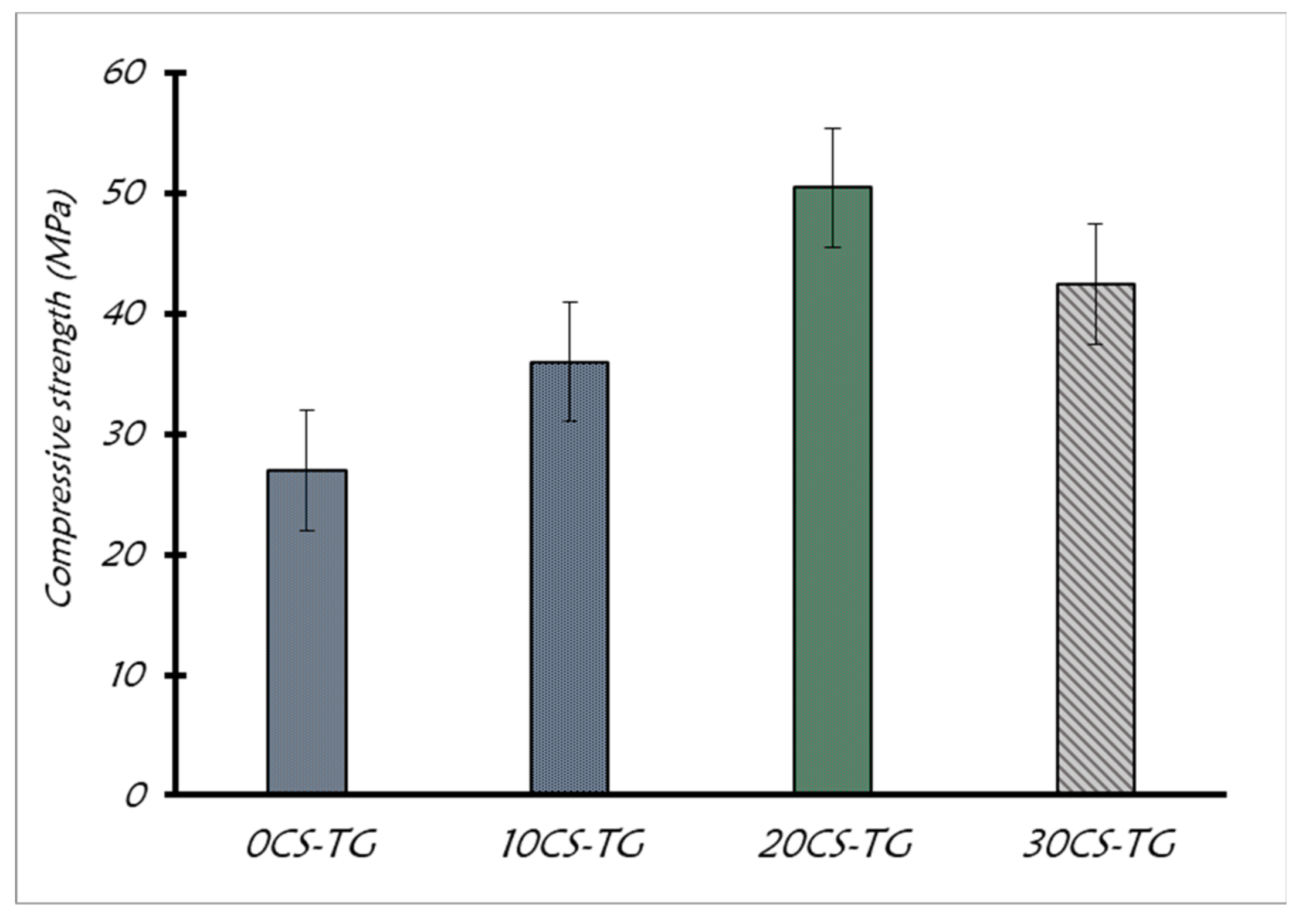
3.3. Mechanical Properties

Formulations were produced using three substitution rates (DS for MK) and the MK reference mixture (Table 5), following the mixing methodology according to standard NF EN 196-6. The mortars were poured into polystyrene molds on a vibrating table. The curing temperature was set at 60 °C to accelerate the geo-polymerization reaction and evolution of strength [38,50]. Mechanical tests were performed on 4 × 4 × 16 cm3 prisms after 7 days of curing. The compressive strength results are shown in Figure 13. Overall, an improvement in compressive strength was noted in mortars with CS compared to the reference mortar without sediment (0CS-TG). The compressive strength increases from 27 MPa for 0CS-TG to 50 MPa for 20CS-TG (substitution of 20% of MK by DS calcined at 750 °C). This improvement may be attributed to the increased availability of Ca provided by the CS or the different physical properties of the CS. A more detailed analysis of the microstructure is provided in the following section to enable a more elaborate explanation behind the cause of the strength gain.

3.4. Microstructural and Environmental Analysis

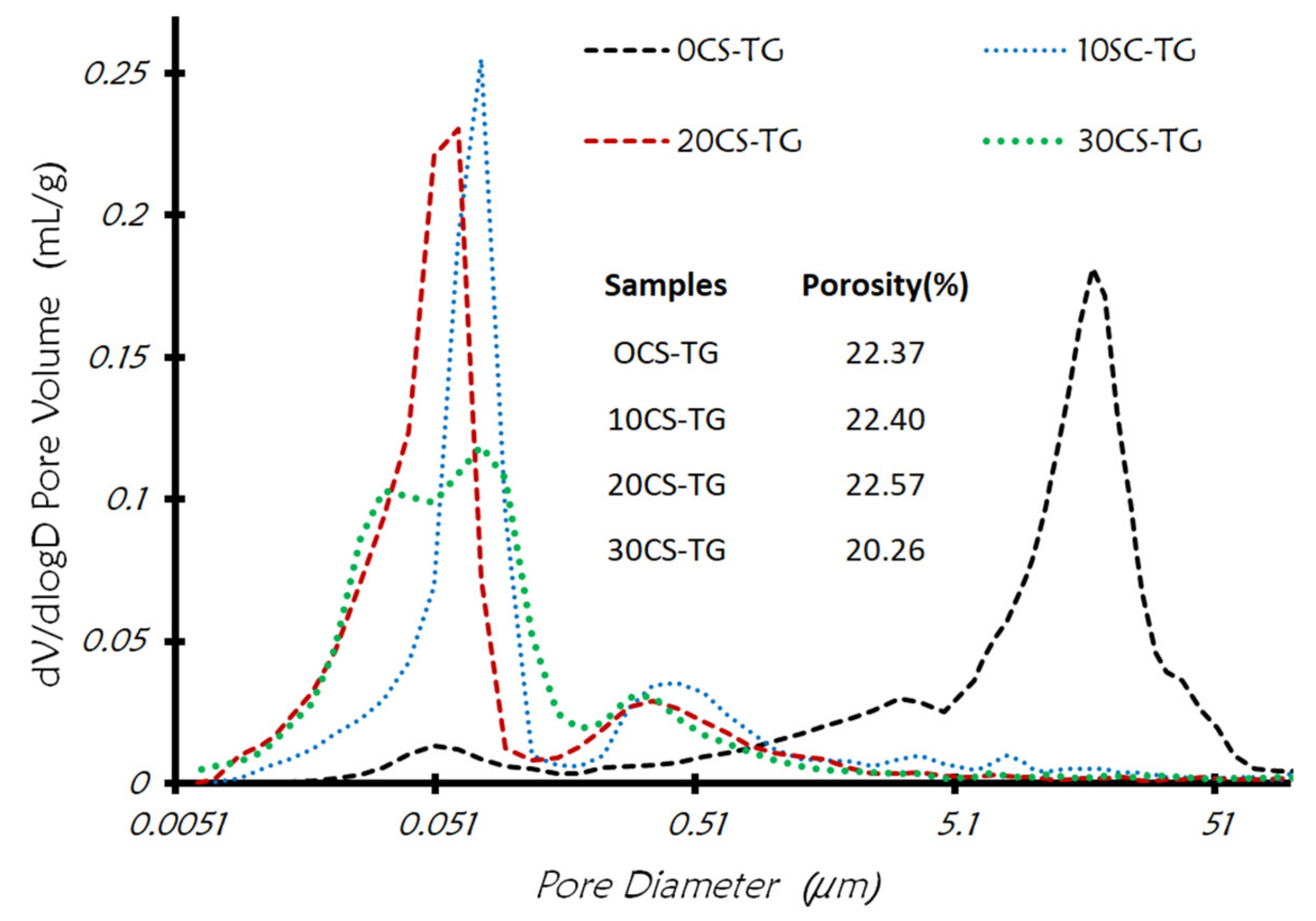
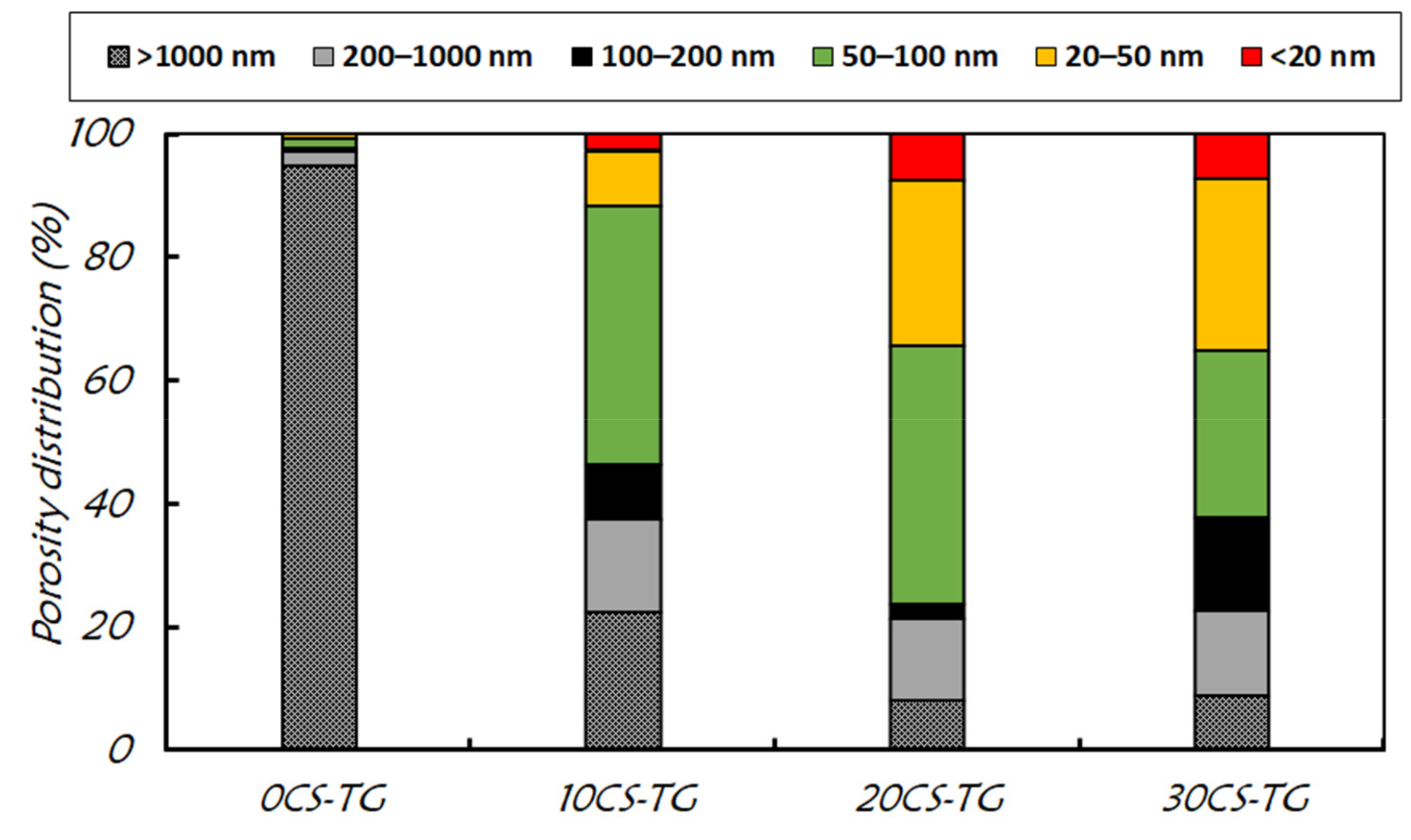
3.4.1. Mercury Intrusion Porosimetry

Pore size distribution has an influence on several properties of mortars and concrete. In particular, the water permeability determines the durability of the matrix for various degradation mechanisms (carbonation and chloride ingress), while the pore size distribution directly controls the freeze–thaw resistance and influences the compressive strength [51,52]. The pore size distributions presented in Figure 14 and Figure 15 highlight the large influence of the addition of CS on pore size reduction (displacement towards porosities of smaller diameters). The reference mortar 0CS-TG contains approximately 95% of pores with diameters greater than 1000 nm (classified as macropores). The addition of DS stimulates pore structure refinement towards porosity with around 50 nm in pore diameter. The 10CS-TG, 20CS-TG, and 30SC-TG mortars achieved mostly pores of 20–50 nm (mesopores) and 50–100 nm (macropores) with an overall percentage of these two types of pores ranging between 55%-70% of the total porosity. The overall porosity determined by the quantity of intruded mercury remains relatively constant (approximately 22% in all mortars).
This change in the distribution of porosities is caused by a wider set of chemical elements provided by the calcined DS on the top of the aluminum and silicon from the MK. The nature of the phases in the CS (the meta-clays incorporating Ca from the decomposition of limestone) show a high reactivity linked to the disordered nature of their structure. Thus, these results indicate the advantage of using CS as an alternative material to improve the characteristics of mortars by refining the pore size distribution. The presence of exchangeable cations (mono and bivalent) (Na+, K+, Mg2+, Ca2+, and Fe2+) increases the distortion of the metastable structure, particularly in clays with a sheet structure. The liberation of elements such as Ca2+ influences the structure of the geopolymer network.

3.4.2. Environmental Study of Mortars

Table 6 summarizes the leachable values of the MMTE and Cl.F, and SO42−. Overall, the values measured in the two matrices 0CS-TG and 20CS-TG show sufficient stabilization of most elements compared to the leaching limits of IW suggested by French Directive No. 0289 [53]. The addition of CS leads to a slight increase in As and Se leaching that exceeds the French IW leaching limits.

3.4.3. SEM-EDS Observation

The SEM-EDS observations of 20CS-TG mortar fragments containing DS-750 °C and TRWG (Figure 16) show several characteristic morphologies of the reaction products of DS-750 °C and TRWG. Figure 16A shows a representative image of the binder resulting from the reaction of DS-750 °C and MK with the activator TRWG. This binder phase is seen in the EDS to be rich in Si and Al. A high concentration of Na is also present in this binder phase with minor amounts of Ca, Fe, Mg and sulfate.
This SEM observation highlights that the interaction between the CS, MK and the activator causes the formation of a binder of the N-A-S-H or geopolymer type. The presence of Ca in this binder influences the porosity, as shown by mercury intrusion. Further, products from carbonation are observed in moderate quantities. A star-shaped precipitate is observed in Figure 16B, wherein no elevated concentrations of Ca are detected; these are probably Na-carbonates. The prismatic in Figure 16C with an elevated concentration of Ca shows the presence of the Ca-carbonate. The measured concentrations by EDS deviate from the pure compositions because of interaction with the surrounding binder. The presence of calcium in the mortar leads to favorable phenomena for the matrix. The first is the participation in the formation of the binder phase, which intervenes in the solidification of the matrix and causes observed pore size refinement. This refinement can be enhanced further by the carbonation observed here by SEM [54,55].

4. Conclusions

This work shows the possibility of the binary valorization of RWG and DS for use as an alkali-activated binder. The main conclusions of this study are as follows:
  • Depending on the chemical nature of RWG (amorphous and siliceous), an alkaline activation is necessary to make the silicon available. The alkaline attack at 10M-NaOH of RWG leads to the formation of an (activator) that is rich in sodium silicates.
  • The thermal activation of DS at 750 °C allows the activation of the aluminosilicate phases and the decarbonation of limestone. The activation of these two elements will help promote the hardening of the matrix because of the participation of lime and activated clays in the formation of the binder phases of (C,N)-A-S-H/geopolymer type. Further, the calcination allows for the degradation of organic materials existing in the sediments.
  • The addition of DS-750 °C in the matrix improves the microstructural properties to reduce porosity and to improve resistance to the compression of the mortar. Similarly, the stabilization of trace elements is very advantageous under the addition of CS.
  • Compared to the reference mortar (with 100% of MK as aluminosilicates and the treated glass as activator (0CS-TG)) the mortar containing 20% of DS-750 °C with the substitution of MK leads to an improvement of mechanical properties in the compression and a strong reduction in harmful porosities. This improvement is explained by the nature of clays and the calcium present in the treated sediments.

Author Contributions

Conceptualization, A.B., W.M. and Y.M.-P.; methodology, A.B.; software, A.B.; validation, A.B., W.M., Y.M.-P., M.B., A.P. and N.-E.A.; formal analysis, A.B.; investigation, A.B., W.M., Y.M.-P. and A.P.; resources, M.B., A.P. and N.-E.A.; data curation, A.B.; writing—original draft preparation, A.B.; writing—review and editing, A.B.; visualization, A.B.; supervision, A.B.; project administration, M.B. and N.-E.A.; funding acquisition, M.B and N.-E.A. All authors have read and agreed to the published version of the manuscript.

Funding

This research was funded by Chaire Ecosed and Water Agency Hauts-de-France.

Acknowledgments

This work was conducted in the laboratory of the civil engineering department of LGCgE-IMT Lille Douai. The authors gratefully acknowledge the useful contribution of the Water Agency (Agence de l’eau des Hauts-de-France) that funded this study. The authors thanks also laboratory assistants from IMT Lille-Douai and Centre Commun de Mesures RMN-Université de Lille for their technical help.

Conflicts of Interest

All authors disclose any financial and personal relationships with other people or organizations that could inappropriately influence their work.

References

  1. Davidovits, J. Geopolymers. J. Therm. Anal. Calorim. 1991, 37, 1633–1656. [Google Scholar] [CrossRef]
  2. McLellan, B.C.; Williams, R.P.; Lay, J.; van Riessen, A.; Corder, G.D. Costs and carbon emissions for geopolymer pastes in comparison to ordinary portland cement. J. Clean. Prod. 2011, 19, 1080–1090. [Google Scholar] [CrossRef] [Green Version]
  3. Duxson, P.; Fernández-Jiménez, A.; Provis, J.L.; Lukey, G.C.; Palomo, Á.; Van Deventer, J.S.J. Geopolymer technology: The current state of the art. J. Mater. Sci. 2007, 42, 2917–2933. [Google Scholar] [CrossRef]
  4. Chen-Tan, N.W.; Van Riessen, A.; Ly, C.V.; Southam, D.C. Determining the Reactivity of a Fly Ash for Production of Geopolymer. J. Am. Ceram. Soc. 2009, 92, 881–887. [Google Scholar] [CrossRef]
  5. Lee, W.; van Deventer, J. Structural reorganisation of class F fly ash in alkaline silicate solutions. Colloids Surfaces A: Physicochem. Eng. Asp. 2002, 211, 49–66. [Google Scholar] [CrossRef]
  6. Hajimohammadi, A.; Ngo, T.; Vongsvivut, J. Interfacial chemistry of a fly ash geopolymer and aggregates. J. Clean. Prod. 2019, 231, 980–989. [Google Scholar] [CrossRef]
  7. Hajimohammadi, A.; van Deventer, J.S. Dissolution behaviour of source materials for synthesis of geopolymer binders: A kinetic approach. Int. J. Miner. Process. 2016, 153, 80–86. [Google Scholar] [CrossRef]
  8. Hajimohammadi, A.; Provis, J.L.; Van Deventer, J.S.J. Effect of Alumina Release Rate on the Mechanism of Geopolymer Gel Formation. Chem. Mater. 2010, 22, 5199–5208. [Google Scholar] [CrossRef]
  9. Gasteiger, H.A.; Frederick, W.J.; Streisel, R.C. Solubility of aluminosilicates in alkaline solutions and a thermodynamic equilibrium model. Ind. Eng. Chem. Res. 1992, 31, 1183–1190. [Google Scholar] [CrossRef]
  10. Fillenwarth, B.A.; Sastry, S.M. Development of a predictive optimization model for the compressive strength of sodium activated fly ash based geopolymer pastes. Fuel 2015, 147, 141–146d. [Google Scholar] [CrossRef]
  11. Bouchikhi, A.; Benzerzour, M.; Abriak, N.-E.; Maherzi, W.; Mamindy-Pajany, Y. Study of the impact of waste glasses types on pozzolanic activity of cementitious matrix. Constr. Build. Mater. 2019, 197, 626–640. [Google Scholar] [CrossRef]
  12. Torres-Carrasco, M.; Puertas, F. Waste glass in the geopolymer preparation. Mechanical and microstructural characterisation. J. Clean. Prod. 2015, 90, 397–408. [Google Scholar] [CrossRef]
  13. Torres-Carrasco, M.; Palomo, J.G.; Puertas, F. Sodium silicate solutions from dissolution of glasswastes. Statistical analysis. Materiales de Construcción 2014, 64, e014. [Google Scholar] [CrossRef] [Green Version]
  14. Rincon, J.M.; Romero, M.; Díaz, C.; Balek, V.; Malek, Z. Thermal Behaviour of Silica Waste from a Geothermal Power Station and Derived Silica Ceramics. J. Therm. Anal. Calorim. 1999, 56, 1261–1269. [Google Scholar] [CrossRef]
  15. Grynberg, J. Mécanismes Physiques et Chimiques Mis en Jeu Lors de la Fusion du Mélange SiO2-Na2CO3. Ph.D. Thesis, Pierre et Marie Curie, Paris, France, 2013. [Google Scholar]
  16. Hamer, K.; Karius, V. Brick production with dredged harbour sediments. An industrial-scale experiment. Waste Manag. 2002, 22, 521–530. [Google Scholar] [CrossRef]
  17. Amar, M.; Benzerzour, M.; Safhi, A.E.M.; Abriak, N.-E. Durability of a cementitious matrix based on treated sediments. Case Stud. Constr. Mater. 2018, 8, 258–276. [Google Scholar] [CrossRef]
  18. Snellings, R.; Cizer, Ö.; Horckmans, L.; Durdziński, P.T.; Dierckx, P.; Nielsen, P.; Van Balen, K.; Vandewalle, L. Properties and pozzolanic reactivity of flash calcined dredging sediments. Appl. Clay Sci. 2016, 129, 35–39. [Google Scholar] [CrossRef]
  19. Safhi, A.E.M.; Rivard, P.; Yahia, A.; Benzerzour, M.; Khayat, K.H. Valorization of dredged sediments in self-consolidating concrete: Fresh, hardened, and microstructural properties. J. Clean. Prod. 2020, 263, 121472. [Google Scholar] [CrossRef]
  20. Jeans, C.V. Handbook of Clay Science. Developments in Clay Science Series. Geol. Mag. 2008, 145, 444. [Google Scholar] [CrossRef]
  21. Provis, J.L.; Bernal, S.A. Geopolymers and Related Alkali-Activated Materials. Annu. Rev. Mater. Res. 2014, 44, 299–327. [Google Scholar] [CrossRef]
  22. ISO 18757. Fine Ceramics (Advanced Ceramics, Advanced Technical Ceramics)—Determination of Specific Surface Area of Ceramic Powders by Gas Adsorption Using the BET Method; ISO: Geneva, Switzerland, 2003. [Google Scholar]
  23. NF EN 1097-7. Tests for Mechanical and Physical Properties of Aggregates—Part 7: Determination of the Particle Density of Filler—Pyknometer Method; BSI: London, UK, 2008. [Google Scholar]
  24. ISO15901-1. Evaluation of Pore Size Distribution and Porosity of Solid Materials by Mercury Porosimetry and Gas Adsorption-Part 1: Mercury Porosimetry; ISO: Geneva, Switzerland, 2016. [Google Scholar]
  25. NF-EN 196-1. Methods of Testing Cement—Part 1: Determination of Strength, European Committee for Standardization; BSI: London, UK, 2016; pp. 1–33. [Google Scholar]
  26. Bouchikhi, A.; Mamindy-Pajany, Y.; Maherzi, W.; Albert-Mercier, C.; El-Moueden, H.; Benzerzour, M.; Peys, A.; Abriak, N.-E. Use of residual waste glass in an alkali-activated binder—Structural characterization, environmental leaching behavior and comparison of reactivity. J. Build. Eng. 2021, 34, 101903. [Google Scholar] [CrossRef]
  27. NF EN 12457-2. Leaching-Compliance Test for Leachingof Granular Waste Materials and SludgesPart 2: One Stage Batch Test at a Liquid to Solid Ratio of 10 l/kgfor Materials with Particle Size Below 4 mm (without or with Size Reduction); BSI: London, UK, 2002.
  28. Fernandez Lopez, R.L.A. Calcined Clayey Soils as a Potential Replacement for Cement in Developing Countries. Ph.D. Thesis, École polytechnique fédérale de Lausanne, Lausanne, Switzerland, 6 February 2009. [Google Scholar] [CrossRef]
  29. Skibsted, J.; Snellings, R. Reactivity of supplementary cementitious materials (SCMs) in cement blends. Cem. Concr. Res. 2019, 124, 105799. [Google Scholar] [CrossRef]
  30. Fernandez, R.; Martirena, F.; Scrivener, K.L. The origin of the pozzolanic activity of calcined clay minerals: A comparison between kaolinite, illite and montmorillonite. Cem. Concr. Res. 2011, 41, 113–122. [Google Scholar] [CrossRef]
  31. Danner, T.; Norden, G.; Justnes, H. Characterisation of calcined raw clays suitable as supplementary cementitious materials. Appl. Clay Sci. 2018, 162, 391–402. [Google Scholar] [CrossRef]
  32. Machacek, J.; Gedeon, O.; Liška, M. Group connectivity in binary silicate glasses. J. Non-Cryst. Solids 2006, 352, 2173–2179. [Google Scholar] [CrossRef]
  33. Maekawa, H.; Maekawa, T.; Kawamura, K.; Yokokawa, T. The structural groups of alkali silicate glasses determined from 29Si MAS-NMR. J. Non-Cryst. Solids 1991, 127, 53–64. [Google Scholar] [CrossRef]
  34. Zhang, M.; El-Korchi, T.; Zhang, G.; Liang, J.; Tao, M. Synthesis factors affecting mechanical properties, microstructure, and chemical composition of red mud–fly ash based geopolymers. Fuel 2014, 134, 315–325. [Google Scholar] [CrossRef]
  35. Essaidi, N.; Samet, B.; Baklouti, S.; Rossignol, S. Feasibility of producing geopolymers from two different Tunisian clays before and after calcination at various temperatures. Appl. Clay Sci. 2014, 88–89, 221–227. [Google Scholar] [CrossRef]
  36. Chakchouk, A.; Samet, B.; Mnif, T. Study on the potential use of Tunisian clays as pozzolanic material. Appl. Clay Sci. 2006, 33, 79–88. [Google Scholar] [CrossRef]
  37. Izquierdo, M.; Querol, X.; Davidovits, J.; Antenucci, D.; Nugteren, H.; Fernández-Pereira, C. Coal fly ash-slag-based geopolymers: Microstructure and metal leaching. J. Hazard. Mater. 2009, 166, 561–566. [Google Scholar] [CrossRef]
  38. Pouhet, R. Formulation and Durability of Metakaolin-Based Geopolymers. Ph.D. Thesis, Université de Toulouse, Université Toulouse III-Paul Sabatier, Toulouse, France, 2015. [Google Scholar] [CrossRef]
  39. Benzerzour, M.; Maherzi, W.; Amar, M.A.A.; Abriak, N.-E.; Damidot, D. Formulation of mortars based on thermally treated sediments. J. Mater. Cycles Waste Manag. 2018, 20, 592–603. [Google Scholar] [CrossRef]
  40. Drachman, S.; Roch, G.; Smith, M. Solid state NMR characterisation of the thermal transformation of Fuller’s Earth. Solid State Nucl. Magn. Reson. 1997, 9, 257–267. [Google Scholar] [CrossRef]
  41. Autef, A.; Joussein, E.; Gasgnier, G.; Pronier, S.; Sobrados, I.; Sanz, J.; Rossignol, S. Role of metakaolin dehydroxylation in geopolymer synthesis. Powder Technol. 2013, 250, 33–39. [Google Scholar] [CrossRef]
  42. Singh, N.B. Fly Ash-Based Geopolymer Binder: A Future Construction Material. Minerals 2018, 8, 299. [Google Scholar] [CrossRef] [Green Version]
  43. Carroll, D.; Kemp, T.; Bastow, T.; Smith, M. Solid-state NMR characterisation of the thermal transformation of a Hungarian white illite. Solid State Nucl. Magn. Reson. 2005, 28, 31–43. [Google Scholar] [CrossRef] [PubMed] [Green Version]
  44. Zhou, L.; Guo, J.; Yang, N.; Li, L. Solid-state nuclear magnetic resonance and infrared spectroscopy of alkali feldspars. Sci. China Ser. D Earth Sci. 1997, 40, 159–165. [Google Scholar] [CrossRef]
  45. Slimanou, H.; Bouguermouh, K.; Bouzidi, N. Synthesis of geopolymers based on dredged sediment in calcined and uncalcined states. Mater. Lett. 2019, 251, 188–191. [Google Scholar] [CrossRef]
  46. Trindade, M.; Dias, M.; Coroado, J.; Rocha, F. Mineralogical transformations of calcareous rich clays with firing: A comparative study between calcite and dolomite rich clays from Algarve, Portugal. Appl. Clay Sci. 2009, 42, 345–355. [Google Scholar] [CrossRef]
  47. Cherki El Idrissi, A. Géopolymérisation et Activation Alcaline des Coulis D’injection: Structuration, Micromécanique et Résistance aux Sollicitations Physico-Chimiques. Ph.D. Thesis, École Doctorale Sciences Pour l’ingénieur, Géosciences, Architecture, Nantes, France, December 2016. Available online: https://tel.archives-ouvertes.fr/tel-02193725 (accessed on 25 April 2020).
  48. Brown, I.W.M.; MacKenzie, K.J.D.; Meinhold, R.H. The thermal reactions of montmorillonite studied by high-resolution solid-state29Si and27Al NMR. J. Mater. Sci. 1987, 22, 3265–3275. [Google Scholar] [CrossRef]
  49. Jakobsen, H.J.; Jacobsen, H. Solid state 27Al and 29Si MAS n.m.r. studies on diagenesis of mixed layer silicates in oil source rocks. J. Périnat. Med. 1988, 16, 67–75. [Google Scholar] [CrossRef]
  50. Khale, D.; Chaudhary, R. Mechanism of geopolymerization and factors influencing its development: A review. J. Mater. Sci. 2007, 42, 729–746. [Google Scholar] [CrossRef]
  51. Vaganov, V.; Popov, M.; Korjakins, A.; Šahmenko, G. Effect of CNT on Microstructure and Minearological Composition of Lightweight Concrete with Granulated Foam Glass. Procedia Eng. 2017, 172, 1204–1211. [Google Scholar] [CrossRef]
  52. Cheng, S.; Shui, Z.; Sun, T.; Yu, R.; Zhang, G. Durability and microstructure of coral sand concrete incorporating supplementary cementitious materials. Constr. Build. Mater. 2018, 171, 44–53. [Google Scholar] [CrossRef]
  53. Decree-Ministerial, Decree of 12/12/14 Relating to the Conditions of Admission of Inert Waste in Facilities Falling under Headings 2515, 2516, 2517 and in Inert Waste Storage Facilities Falling under Heading 2760 of the Nomenclature of Classified Facilities. 2014. Available online: https://aida.ineris.fr/consultation_document/33657 (accessed on 15 September 2020).
  54. Vu, T.H.; Gowripalan, N.; De Silva, P.; Paradowska, A.; Garbe, U.; Kidd, P.; Sirivivatnanon, V. Assessing carbonation in one-part fly ash/slag geopolymer mortar: Change in pore characteristics using the state-of-the-art technique neutron tomography. Cem. Concr. Compos. 2020, 114, 103759. [Google Scholar] [CrossRef]
  55. Branch, J.; Epps, R.; Kosson, D. The impact of carbonation on bulk and ITZ porosity in microconcrete materials with fly ash replacement. Cem. Concr. Res. 2018, 103, 170–178. [Google Scholar] [CrossRef]
Figure 1. Particle size distributions of sand, RWG, MK and DS.
Sustainability 13 04960 g001
Figure 2. Thermogravimetric and differential scanning calorimetric analysis of raw sediments.
Sustainability 13 04960 g002
Figure 3. Evolved gas analysis of raw sediments during TGA-MS.
Sustainability 13 04960 g003
Figure 4. Relationship between connectivity of the silicate network and degree of reactivity (stability).
Sustainability 13 04960 g004
Figure 5. Evolution of phase composition at different temperatures of calcination given by XRD analysis.
Sustainability 13 04960 g005
Figure 6. Evolution of pH as a function of calcination temperature and concentration of sediment.
Sustainability 13 04960 g006
Figure 7. Evolution of electrical conductivity as a function of calcination temperature and concentration of sediment.
Sustainability 13 04960 g007
Figure 8. Leaching behavior, SSA BET and density of the DS and DS-calcined.
Sustainability 13 04960 g008
Figure 9. 29Si-NMR spectra of metakaolin (MK), DS and DS-750 °C.
Sustainability 13 04960 g009
Figure 10. 27Al-NMR and DS. Spinning side bands (SSBs) are marked with an asterisk (*).
Sustainability 13 04960 g010
Figure 11. 27Al-NMR on MK. Spinning side bands (SSBs) are marked with an asterisk (*).
Sustainability 13 04960 g011
Figure 12. Chemical analysis (A) by XRF and leaching behavior (B) of (Si + Al), (Ca + Na) and (Ca + Mg).
Sustainability 13 04960 g012
Figure 13. Compressive strength of mortars at 7 days of curing at 60 °C.
Sustainability 13 04960 g013
Figure 14. Pore size distribution obtained from mercury intrusion porosimetry.
Sustainability 13 04960 g014
Figure 15. Distribution of porosities accessible to mercury.
Sustainability 13 04960 g015
Figure 16. SEM observations of mortars 20CS-TG. (A) binder resulting from the reaction of DS-750, (B) Na-(Si/Al) precipitate and (C) Ca-carbonate.
Sustainability 13 04960 g016
Table 1. Physical characterization of DS, RWG and MK.
ParametersDSRWGMKStandard/Method
Absolute density (g/cm3)2.752.542.62NF EN 1097-7
SSA (m2/kg)12,500792.69470NF EN ISO18757
LOI % (450 °C/3 h)10.430.020.20NF EN P94-051
LOI % (550 °C/1 h)11.220.030.50NF EN 15169
LOI % (1000 °C/1 h)12.50.42.00NF EN 1097-7
d10 (µm)0.402.4010.00NF ISO 13320-1
d50 (µm)40.006.506.7
d90(µm)6313.522.8
Table 2. Elemental chemical composition of DS, RWG and MK (measured by XRF, values in wt%).
Element (%)DSRWGMK
CPrésent00
O50.546.953.1
Na0.59.5Traces
Mg0.70.70.1
Al6.51.216.1
Si2731.727.5
K2Traces0.2
Fe5.1Traces1.5
Ca5.4Traces0.7
CrTraces0.1Traces
P0.8TracesTraces
S0.5TracesTraces
Ti0.5TracesTraces
Table 3. Chemical composition of DS, RWG and MK (measured by XRF, values in wt%).
OxidesDSRWGMK
Na2O0.6613.58Traces
MgO1.211.180.28
Al2O312.21.6122.43
SiO257.870.8673.73
K2O2.450.690.20
Fe2O37.330.410.99
CaO7.5511.521.27
Cr2O3Traces0.15Traces
P2O51.81TracesTraces
SO31.20TracesTraces
TiO20.87Traces1.09
Total93.0810099.99
LOI6.9200.01
Table 4. Evolution of pH and electrical conductivity for DS and DS-C (L/S = 10).
SamplespHEc (mS/cm)
DS7.250.9
DS-4507.831.25
DS-5508.341.2
DS-65011.91.63
DS-75012.67.03
DS-85012.45.45
DS-95012.34.17
MK90.13
Table 5. Composition and condition of mortar treatment.
Sand/(MK + CS)Water/(TG + MK + CS)TRWG/(MK + CS)CS/(MK + CS)
0CS-TG30.450.220
10CS-TG30.450.220.10
20CS-TG30.450.220.20
30CS-TG30.450.220.30
Table 6. Environmental leaching test results.
Elements0CS-TG20CS-TGRSD 1IWNHW
Anionic and MMTE mobility (mg/kg)As<0.0050.61.20.52
Ba<0.008<0.008-20100
Cd<0.007<0.0071.80.041
Cr<0.0070.22.20.510
Cu0.03<0.0050.5250
Hg<0.003<0.003-0.22
Mo0.31<0.074.30.510
Ni<0.07<0.073.70.410
Pb<0.060.073.80.510
Sb0.12<0.062.90.060.7
Se0.150.34.30.10.5
Zn<0.04<0.04-450
Chlorine255.4-80015000
Fluorine191-10150
Sulphates11547.6-100020000
1 RSD: Relative standard deviation ICP-AES is presented by (%).
Publisher’s Note: MDPI stays neutral with regard to jurisdictional claims in published maps and institutional affiliations.

