Article

Turbulent Flow Heat Transfer through a Circular Tube with Novel Hybrid Grooved Tape Inserts: Thermohydraulic Analysis and Prediction by Applying Machine Learning Model

by
Suvanjan Bhattacharyya
1,
Devendra Kumar Vishwakarma
1,
Shramona Chakraborty
2,
Rahul Roy
2,
Alibek Issakhov
3 and
Mohsen Sharifpur
4,5,*
1
Department of Mechanical Engineering, Birla Institute of Technology and Science, Pilani, Pilani Campus, Vidya Vihar, Pilani 333 031, Rajasthan, India
2
Department of Computer Science and Engineering, Indian Institute of Technology, Kharagpur-721 302, West Bengal, India
3
Faculty of Mechanics and Mathematics, Department of Mathematical and Computer Modelling, Al-Farabi Kazakh National University, Almaty 050040, Kazakhstan
4
Clean Energy Research Group, Department of Mechanical and Aeronautical Engineering, Engineering III, University of Pretoria, Lynnwood Road, Pretoria 0002, South Africa
5
Department of Medical Research, China Medical University Hospital, China Medical University, Taichung 404, Taiwan
*
Author to whom correspondence should be addressed.
Sustainability 2021, 13(6), 3068; https://doi.org/10.3390/su13063068
Submission received: 21 December 2020 / Revised: 20 February 2021 / Accepted: 24 February 2021 / Published: 11 March 2021

Abstract

:
The present experimental work is performed to investigate the convection heat transfer (HT), pressure drop (PD), irreversibility, exergy efficiency and thermal performance for turbulent flow inside a uniformly heated circular channel fitted with novel geometry of hybrid tape. Air is taken as the working fluid and the Reynolds number is varied from 10,000 to 80,000. Hybrid tape is made up of a combination of grooved spring tape and wavy tape. The results obtained with the novel hybrid tape show significantly better performance over individual tapes. A correlation has been developed for predicting the friction factor (f) and Nusselt number (Nu) with novel hybrid tape. The results of this investigation can be used in designing heat exchangers. This paper also presented a statistical analysis of the heat transfer and fluid flow by developing an artificial neural network (ANN)-based machine learning (ML) model. The model is trained based on the features of experimental data, which provide an estimation of experimental output based on user-defined input parameters. The model is evaluated to have an accuracy of 98.00% on unknown test data. These models will help the researchers working in heat transfer enhancement-based experiments to understand and predict the output. As a result, the time and cost of the experiments will reduce.

1. Introduction

Energy is necessary for the continuity of the world and so is its conservation. Every day a lot of energy gets wasted in the form of unavailable energy. Due to low efficiency of thermal equipment, energy is poured down the drain. There are several ways to improve the performance of thermal devices, namely Active methods, Passive methods and Combined methods of heat transfer enhancement. Active methods of heat transfer enhancement utilize the power from external sources to enhance the thermal transfer and the equipment required to do so is very costly [1,2,3,4]. Hence, researchers switched to passive technique of thermal enhancement in which swirl devices [5,6,7,8,9], roughness [10,11,12,13,14,15], nanoparticles [16,17,18,19,20,21], obstructions of various geometries, channel modification [22,23,24,25,26,27,28], surface enhancement [29,30,31], etc. are employed to promote the disturbance in the flow field which results in a higher heat transfer rate. Swirl generators are the devices used for intensifying the disturbance in the flow field, which results in an enhanced thermal exchange rate. Swirl generators have been thoroughly investigated by many researchers in the past decades to improve the thermal performance of equipment. The device helps in energy conservation by improving the thermal exchange rate as well as by utilizing available energy in a better way. Twisted and Spring Tapes [24,32,33,34,35,36], Wire coils [26,37,38,39,40], longitudinal vortex generators [41,42,43,44], circular and conical ring inserts [45,46,47,48,49,50], obstruction of different geometries [51,52,53,54], etc. are some examples of swirl generators. Among all of the swirl generators, twisted tape inserts are the most studied and/or found applications in various thermal equipment due to their simple geometries, high thermal enhancement rate, and easy fabrication.
Bhattacharyya [33] performed an experimental assessment to investigate the impact of the length of swirl generators (Twisted tapes and Spring tapes) on the thermal performance and found that full-length twisted tapes are performed best in terms of heat transfer coefficient when compared with short length twisted tapes and spring tapes. Hosseinnezhad et al. [55] reported on the impact of using double twisted tapes of different twist ratio (2.5–4) in both co-swirl and counter swirl position inside a tubular heat exchanger in the turbulent flow regime (Re = 10,000–30,000) with Aluminum Oxide/water as working fluid (1–4% volume fraction) and found an enhancement in the average Nusselt number with the increase in volume fraction and decrease in twist ratio for the counter swirl. The study also found that an enhancement in the performance evaluation for both the configurations with counter-swirl reported higher increment. Farshad and Sheikholeslami [56] presented a numerical investigation for heat transfer enhancement using tape inserts and nanofluid in a solar collector plate and reported enhanced heat transfer and a decline in exergy drop with the usage of multi-channel twisted tapes. Hosseinnejad et al. [57] computationally investigated the influence of two tape inserts on the turbulent heat transfer and revealed an increase in average Nusselt number with the reduction in torsion ratio at constant Reynolds number. Keklikcioglu et al. [58] reported on the impact of different arrangement of short length conically designed wire coil swirl generators on the thermal and flow characteristics. The investigation is done for the turbulent flow with Re varied from 4627 to 25,099. The results obtained from the experimental investigation show that converging wire coil arrangement with 60–40 water and EG ratio shows the highest entropy amongst the other arrangement while lowest entropy was reported for diverging wire coil arrangement with pure water. Ahmadi et al. [59] conducted a computational assessment to investigate the impact of using elliptical cut twisted tapes with CuO/water nanofluid (volume fraction 1–4%) as the working fluid on the thermal and flow performance inside a circular pipe. For only nanofluid, maximum Nusselt number and performance factor will be obtained for 4% volume concentration while for the case of a nanofluid along with elliptical cut tapes are 21% higher. In another computational investigation, Zaboli et al. [22] conducted a numerical analysis for thermo-hydraulics of fluid flow inside a corrugated tube fitted with twisted tapes and reported enhancement in thermal transport as well as pressure when results were compared with the results of corrugated tube alone. Obaidi and Sharif [60] reported on the impact of pitch ratio of twisted tapes on the thermal and flow characteristics inside a cylindrical tube and reported that twisted tapes promote thermal transport as well as pressure drop and thermal performance factor was enhanced by 46%. Banihashemi et al. [61] conducted an experimental assessment for the thermal and flow characteristics inside a circular tube fitted with rotating and fixed angular-cut circular disc insert for the turbulent flow with Re varied from 10,000 to 25,000. The rotation of the insert is kept between 50 and 200 rpm. It is reported that the rotating disc shows higher heat transfer with a low-pressure drop when compared with the fixed disc insert. Samruaisin et al. [62,63] performed experimentation to investigate the influence of twisted tapes on the thermal and flow performance and revealed that inserts promote the thermal and flow properties inside the fluid domain which results in the augmentation of heat transfer rate. Pourfattah et al. [64] conducted a numerical investigation for the thermal and flow characteristics inside a rectangular channel employed with vertical twisted tape and optimize the heat transfer and pressure drop using a genetic algorithm (GA). The results predicted by GA are in good agreement with the data obtained from the computational analysis. Outokesh et al. [65] conducted simulations to analyze the impact of curved profile twisted tape on the thermal and flow performance inside a cylindrical channel. The study was conducted in the turbulent flow regime with Re varied from 2500 to 20,000. The results obtained from the investigation show a higher heat transfer rate, pressure drop, and appreciable enhancement in the thermal performance factor. A similar to the above study was conducted by Noorbakhsh et al. [66] and reported that an increase in the no. of fins leads to higher Nusselt number, pressure drop, and thermal performance factor.
Nowadays, machine learning act as a very useful tool in predicting the results with greater accuracy. It also helps in the optimization of the results for maximum performance, developing mathematical models to forecast the data, etc. The researchers used various kinds of algorithms to develop the model, which learns from the experience and predicts the results with more and more accuracy each time. Maddah et al. [67] utilized an artificial neural network (ANN) to predict the efficiency of CuO-H2O nanofluid in a heat pipe and the accuracy of the predicted result from the model prediction is 0.9938. Sadeghzadeh et al. [68] also employed a self-organizing map and Back Propagation-Levenberq-Marquardt algorithm for predicting the thermo-physical properties of TiO2-Al2O3/water nanofluid. Ahmadi et al. [69] employed a genetic algorithm for predicting the pressure drop for CuO-water nanofluid flow. Other authors who utilize machine learning to predict the properties and performance of nanofluids include Baghban et al. [70,71], Maddah et al. [72], Giwa et al. [73], and Ahmadi et al. [74]. Artificial intelligence found application in predicting the performance of solar collectors [75]. However, from the above discussion it is clear that many published works are available in the open literature to support the machine learning in predicting the properties of nanofluids, but no report in the open literature as per the knowledge of authors is reported on predicting the heat transfer and pressure drop.
After an extensive literature review of various research articles, it is found that a lot of research is going on in the field of heat transfer augmentation by employing different geometries of different tapes, specifically twisted tape. This is due to the low cost, easy fabrication, and ease of usage of such swirl devices. The augmentation in thermal transport is appreciable when twisted tapes are employed when compared with other tapes of augmentation, but simultaneously the pressure drop is also high. Researchers used multiple twisted tapes, complex geometries, etc. to further enhance the heat transfer rate. In the present paper, a hybrid turbulator consisting of wavy tape with grooved spring tape is employed. Figure 1 shows the geometry of the hybrid tape. The design of the turbulator is kept simple for easy fabrication of the device and also minimum pressure penalty. The correlations for predicting f and Nu for the novel hybrid tape are developed and presented. Irreversibility, exergy efficiency and thermohydraulic performance are evaluated. According to author’s knowledge, no literature is available on the application of machine learning (ML) to support the prediction of heat transfer (HT) and pressure drop (PD) in a circular channel tube with hybrid grooved tape inserts. However, machine learning is used in predicting the thermo-physical properties of working agents used in the investigations. Hence, the other aim of this work is to investigate the HT and PD in a circular channel fitted with hybrid grooved tape inserts by employing the ML prediction. Additionally, these models will help the future investigators working in the field of HT enhancement-based experiment to understand and predict the output.

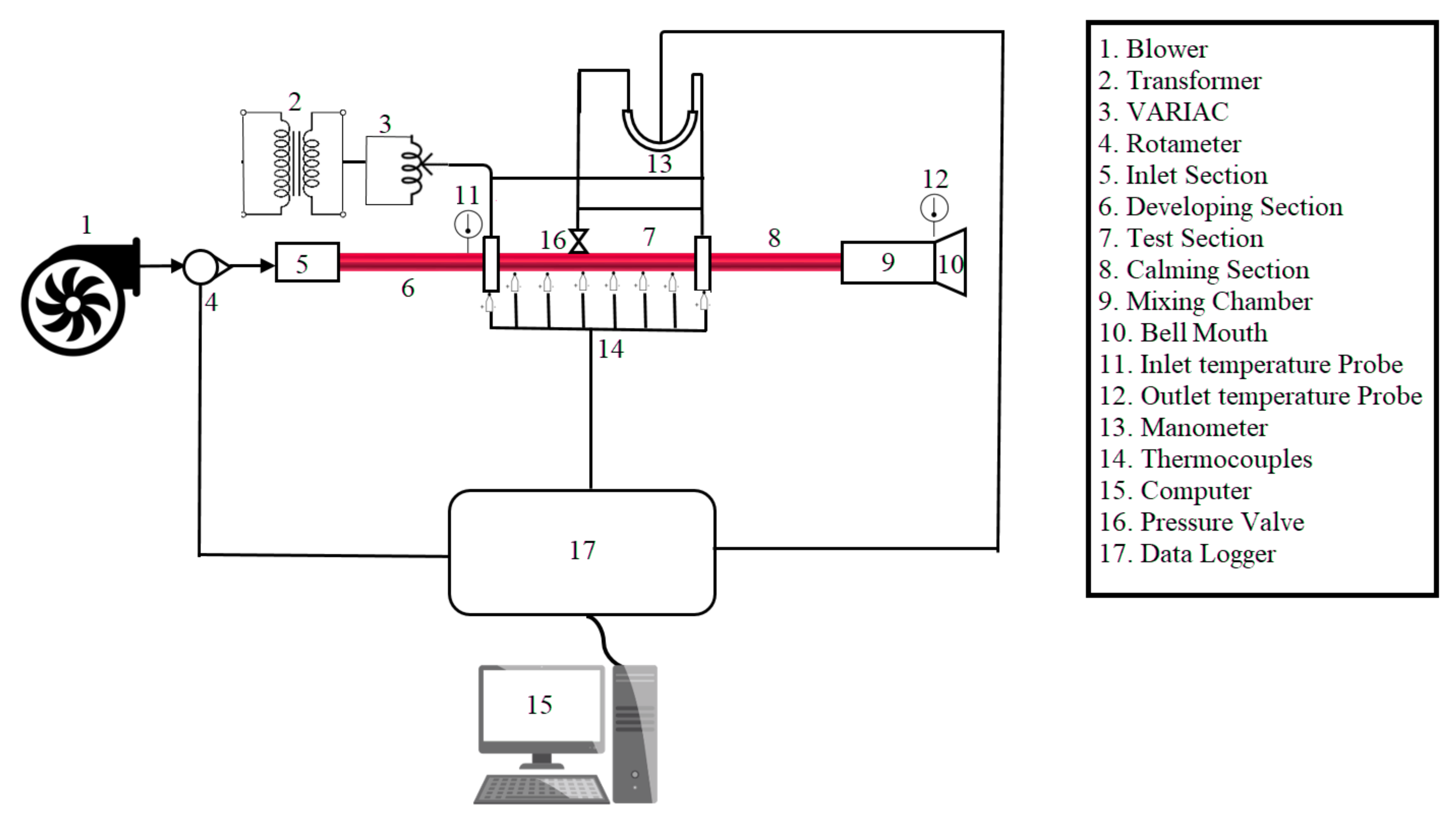
2. Experimental Test Rig and Procedure

Figure 2 shows the schematic representation of the experimental test rig employed for experimental assessment. All the important parts have been leveled in the figure for ease of understanding. Air is taken as the working fluid with Re varied from 10,000 to 80,000.
The atmospheric air is sucked from the environment with the help of a blower of 7 kW capacity and the temperature of the air is assumed to be 25 °C. Air then travels through the calming section which contains a closely packed bundle of straws to soothe the air flow and which allows it to enter with uniform distribution throughout the test section. The test section is uniformly heated to maintain a constant heat flux boundary condition of 2 kW-m−2. A rotameter having a range of 120 to 540 l/h is employed between the calming section and test section to measure the mass flow rate of the working fluid. The design concept of the calming section is acquired from Ghajar and Tam [76] and Tam and Ghajar [77]. A calibrated U-tube manometer having a measuring range between 0 and 150 mm of Hg is used to measure the pressure difference in the test section [78,79,80,81,82,83]. The two ends of the manometer are attached to the test section at a distance of 2100 mm with the help of smooth holes having a diameter 0.10 times the diameter of the test section tube drilled in the channel to ensure the smooth and continuous flow of working fluid and accuracy in the measurement without any losses. The test section is made of a long circular metallic tube having a diameter of 20 mm and a length of 2 m. The hybrid tapes are made up of brass and are 2 m long. The outer surface of the test section is properly insulated to ensure no heat loss to the environment. A total of 36 thermocouples are attached to the surface of the test section at nine equidistant stations to measure the surface temperature of the test section. Four thermocouples at 90° to each other are soldered at each station by drilling a hole on the surface of the test section.
Experiments are conducted in the plain channel for validation of the results obtained with the inserts. The hybrid tapes used for investigations are made of brass. The dimensions of hybrid inserts are 2000 mm long, 1.5 mm thick and width 12 mm.
The system takes approximately 2 h to reach the steady-state condition. The steady-state is assumed when no fluctuations in the reading were noticeably negligible. The bypass valves are used to regulate the fluctuation of flow. The test-section is given a constant heat flux of 2000 W/m2. Once the steady-state is achieved, 400 data are saved in the data acquiring/logger arrangement. A total of 97 experiments are run for plain channel while 195 experimental runs are done with hybrid tape insert. The other details regarding the experimental setup and procedure can be found in the author’s previous work [84].

3. Data Reduction

Experimental investigations have been done for various configurations of hybrid tapes (Figure 1) as given below:
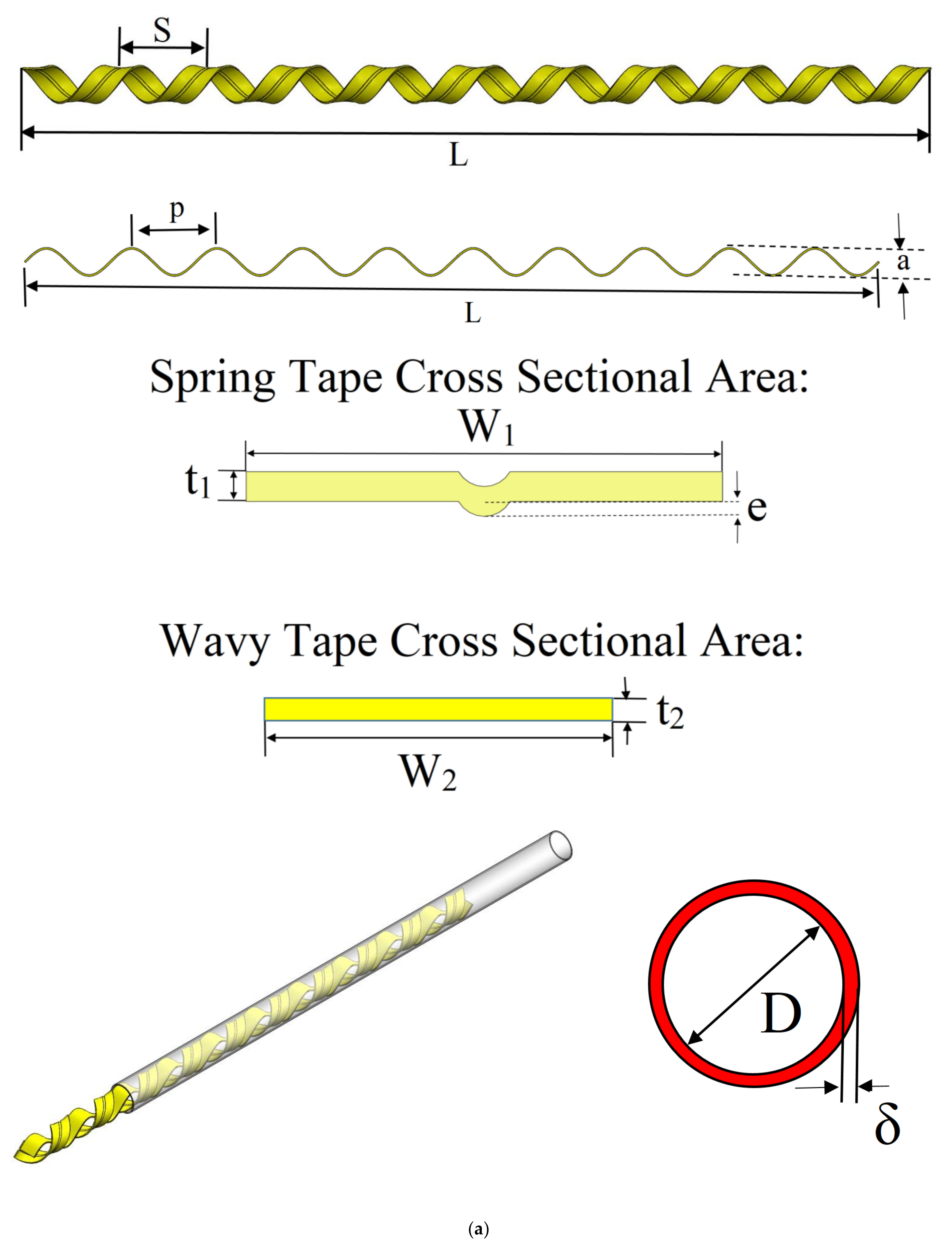
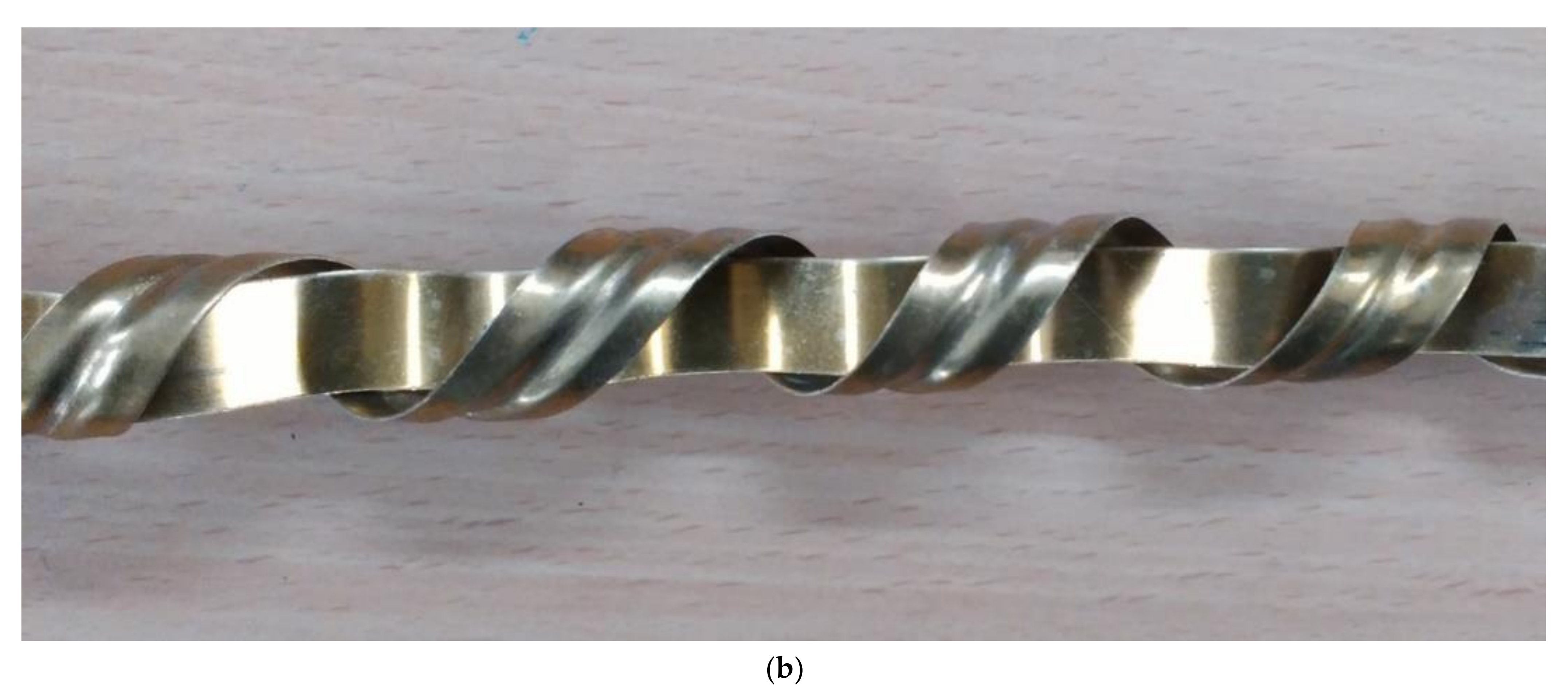
  • Wave ratios (z = p/D) = 1.5, 2.25, and 3.0.
  • Spring ratios (k = s/D) = 1.0, 2.0, and 3.0.
  • Grooved depth ratio: (c = e/W) = 0.16, and 0.25.
  • Channel Diameter (D) = 20.00 mm
  • Length of Channel (L) = 2000.00 mm
  • Tape diameter (W) = 12.00 mm
  • Reynolds number: (Re) = 10,000 to 80,000.
Heat transferred to air is measured by the first law, as expressed below, which states that Qair (the net heat transferred to air) is proportional to the mass flow rate and the specific heat of the working fluid as well as the net temperature difference between outlet and inlet.
Qair = m cp (To − Ti)
To measure the heat leakage from the insulated walls, the balance between the thermal energy absorbed by air and energy supplied by the coils was considered. The energy balance was used to juxtapose the calculated HT rate with electrical power assigned from the heater, Qe = IV, and the difference was defined as energy balance error (EBE), formulated as [24]:
E B E = Q e   Q a i r Q e × 100
The calculation resulted in an average energy balance error amounting to less than 3.3%.
The wall heat flux is determined from:
q w a l l =   Q a i r A
The average of inlet and outlet fluid temperature gives the bulk fluid temperature (Tbulk)
T b u l k =   T o +   T i 2
To calculate the mean inner wall temperature, Twall, a go-around approach is used, where the outer tube wall temperature, Tow, is determined as a mean of measurements obtained from the thermocouples.
The average thermal resistance of the wall (Rwall) is calculated:
T w a l l = T o w Q R w a l l    
The thermal resistance of duct wall (Rwall) is measured using the relation given below, where Do, D represent the outer and inner diameter, respectively, L the length and k the thermal conductivity of the material:
R w a l l = l n D o / D 2 π k B R A S S L      
The convective HT coefficient (hconv), according to Thianpong et al. [7], is:
h c o n v = q w a l l T w a l l T b u l k
The Nusselt number (Nu), with the k here denoting the thermal conductivity of air.
N u = h c o n v D k
f, the Darcy friction coefficient is further evaluated using the formulation:
f = Δ p L D 1 2 ρ V 2
For calculating the ReDh and average Colburn j-factor, the authors referred to Meyer and Everts [85]:
R e D h =   4 × π × D × µ
j =   N u R e D h   × P r 1 3
where the symbols ρ, D, L represent density, inner diameter, and length. V denotes the bulk fluid velocity, calculated from an insert free cross-section and Δp denotes the static pressure drop.
Reynolds number (Re) calculations were based on insert free areas and average fluid velocities, with air properties calculated as a function of bulk fluid temperature (Tbulk).
The thermo-hydraulic performance factor (η) was thus calculated as per Thianpong et al. [7], which gave an understanding of combined performance increments:
η = N u / N u 0 f / f 0 0.33
where the subscript 0 is used to denote the plain duct.
A dimensionless entropy generation number for the total amount of HT is defined as [86]:
N s = S g e n . Q u / T w
A non-dimensional irreversibility factor (ϕ), is defined as [79].
ϕ = N s N s , s m o o t h
For evaluating the process of HT in tube with vortex generator, Zheng et al. [87] presented the exergy efficiency () equation as:
=   E x o u t   E x i n E x w

4. Result and Discussion

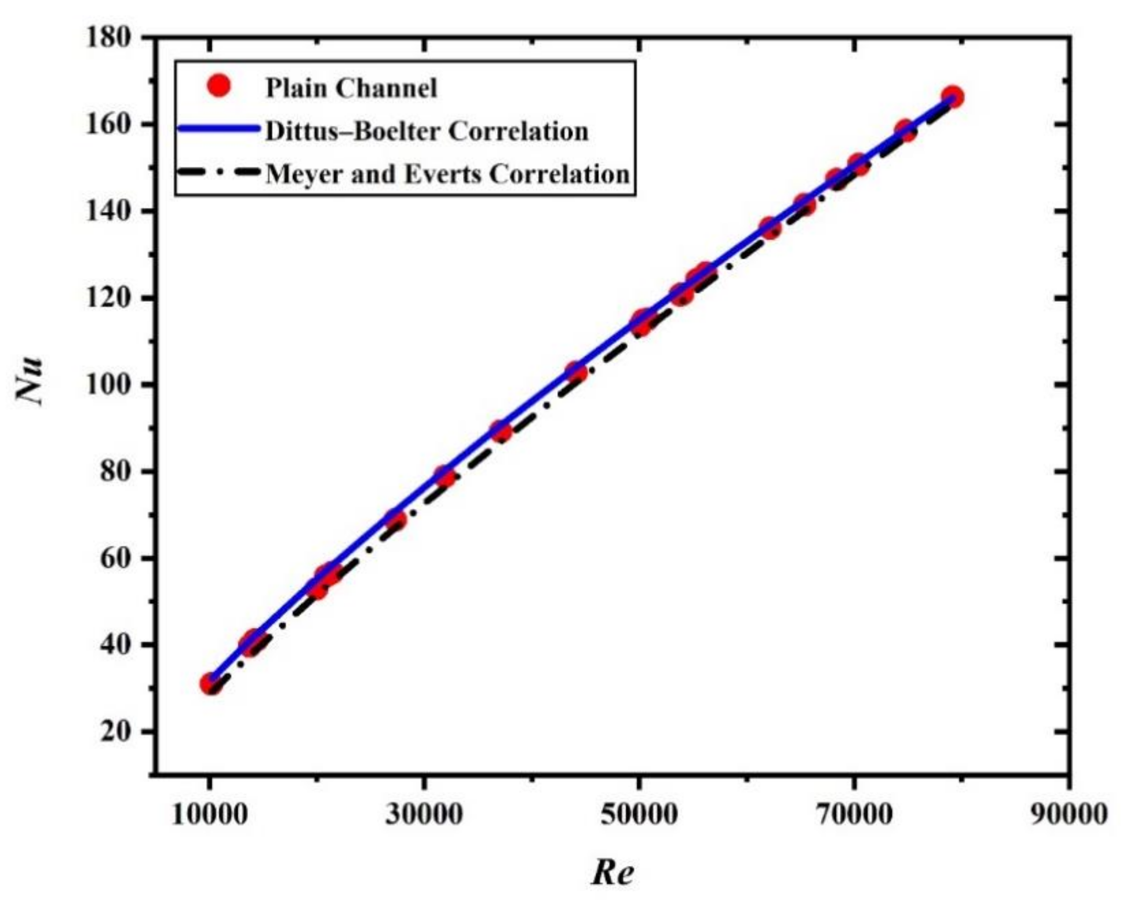
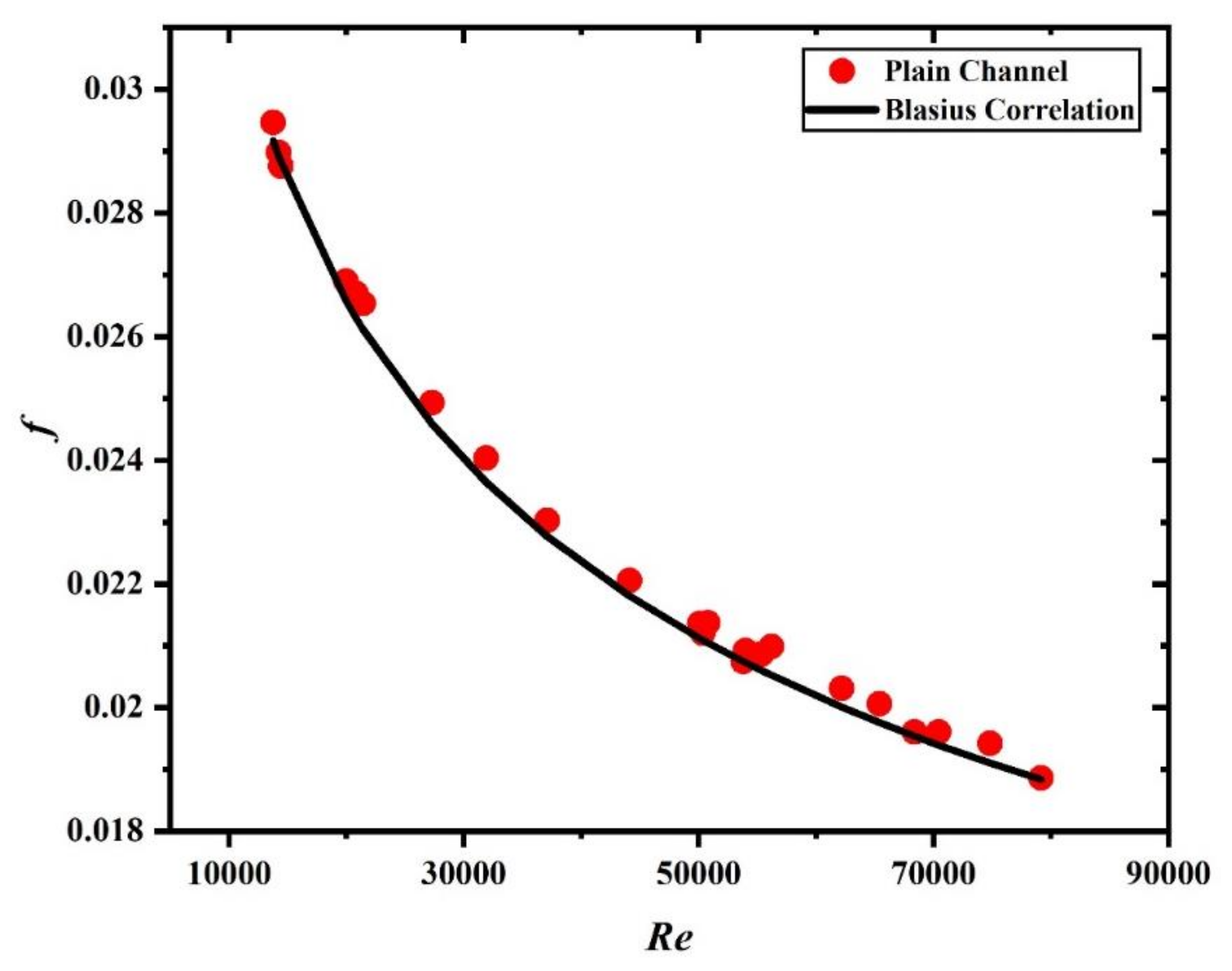
4.1. Validation of Study

Before starting the experiments, all the main equipment of the experimental test rig is tested for uncertainty by following Meyer et al. [88]. This will ensure the accuracy of the obtained results. Maximum error in Re, f and Nu were approximated as ±4.25%, ±5.33% and ±6.02%, respectively.
The results obtained for the smooth tube for Nusselt number and friction factor are validated with the well-established results of Dittus-Boelter correlation [89] and Meyer et al. [88] correlation for Nusselt number and Blasius Correlation [89] for friction factor.
Dittus-Boelter correlation [89] expressed Nusselt number as
N u = 0.023   R e D h 0.8 P r 0.4
Meyer et al. [88] Correlated the Nusselt number as
N u = 0.013   R e D h 0.867 P r 1 3
The correlation for friction factor given by Blasius [89] is given by
f   =   0.3164 R e D h 1 4
Figure 3 and Figure 4 show the validation analysis of the present study with previously established and acclaimed correlations for the Nusselt number and friction factor. The results obtained for the smooth tube for Nusselt number and friction factor are in good accordance with previous studies. The Nusselt number deviates only 5% with Dittus-Boelter correlation and 4% with Meyer and Everts correlation while friction factor differs only 6% with data obtained using Blasius Correlation.

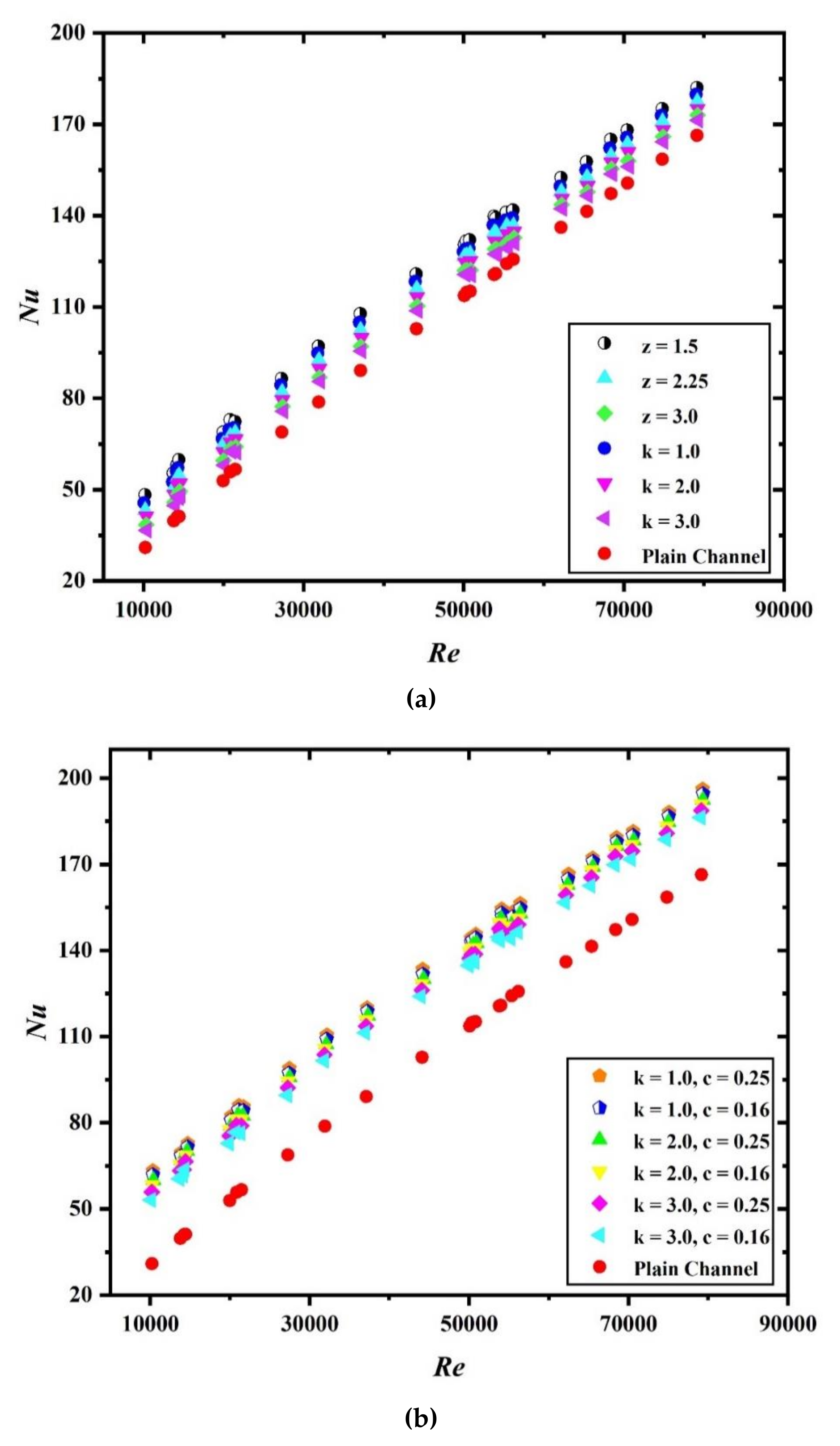
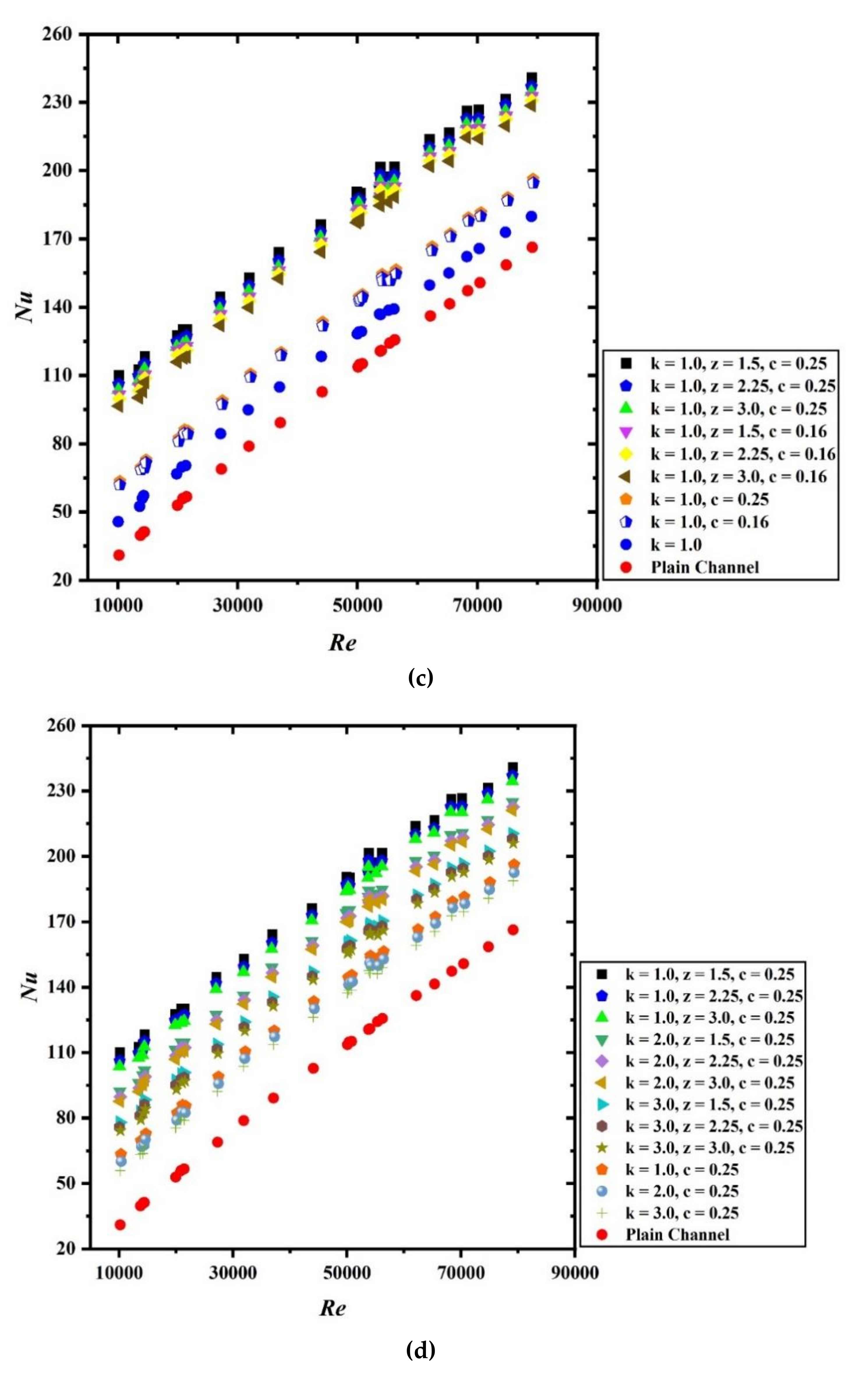
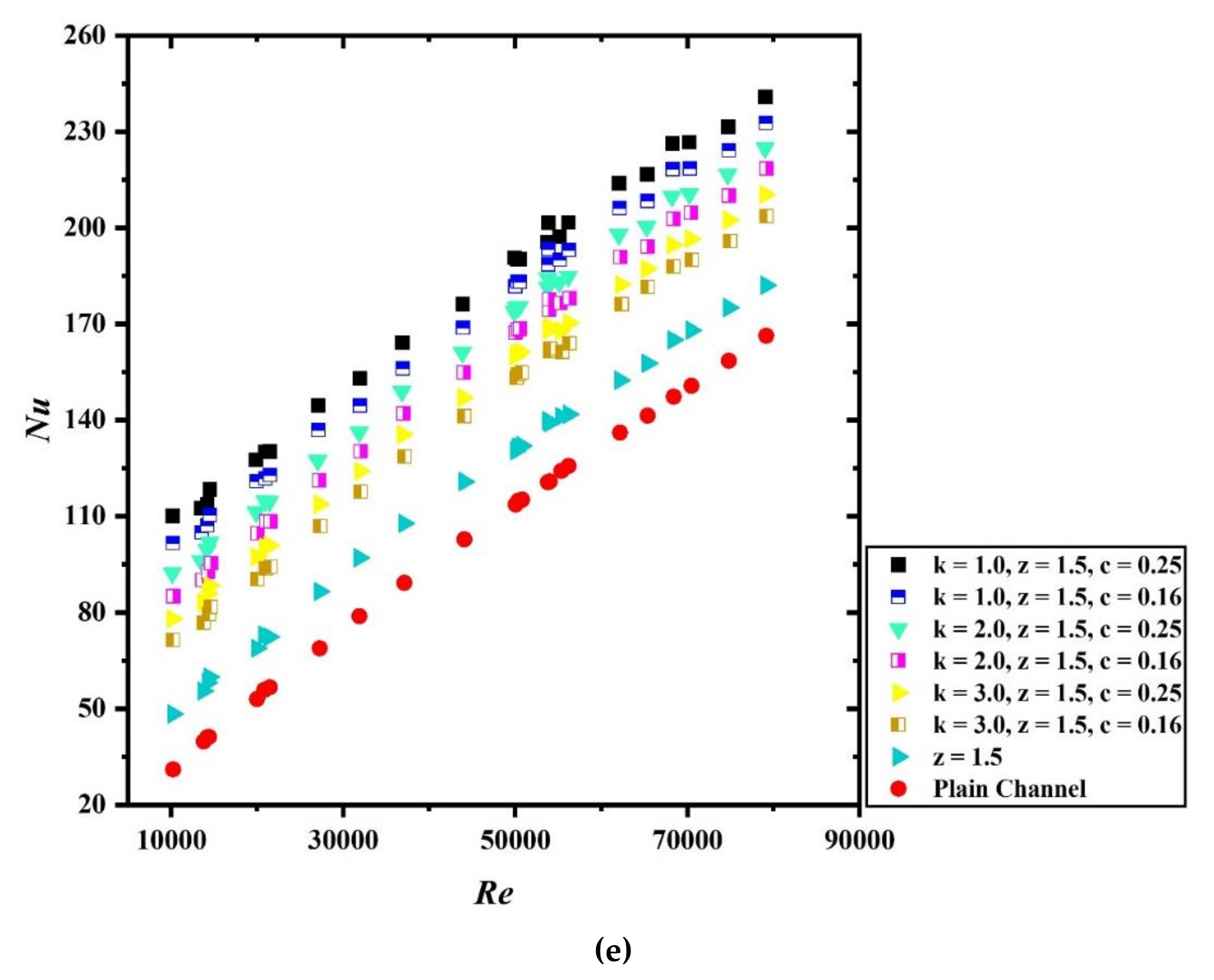
4.2. Influence of Hybrid Tapes on the Heat Transfer

The main aim of this experimental assessment is to evaluate the influence of hybrid tape on heat transfer augmentation and pressure drop. Figure 5a shows the plot for change in Nusselt number with Reynolds number when wavy tape and spring tape are acting alone. The result for both the cases is compared with the Nusselt number results obtained for the smooth tube. It is clear from the plot that an increase in Reynolds number results in a higher Nusselt number value. Further enhancement in the average Nusselt number is visible when inserts are employed for the investigation. For z = 1.5, the Nusselt number is highest for all values of Re, while increasing the value of z from 1.5 to 3.0 results in the decrease in the Nusselt number value. Similarly, for k = 1.0, the Nusselt number shows the maximum surge and for k = 3.0 shows the least value of the Nusselt number for all Re. Overall, the highest enhancement in Nu is noted for z = 1.5 followed by k = 1.0 for all values of Re.
Figure 5b shows the plot for grooved spring tape acting alone and compared the different combinations of k and c with the plain tube. A significant augmentation in the average value of the average Nusselt number is noted. For k = 1.0 and c = 0.25, the Nusselt number value is highest for all Re followed, while the least enhancement is reported for the case of k = 3.0 and c = 0.16. Hence, it can be concluded that a groove on the surface of tape helps in further enhancement of the Nusselt number value while increasing the value of spring ratio, resulting in the decrease in Nusselt number. Moreover, increasing the groove depth also results in a higher Nusselt value. The grooved surface of the insert introduced disturbance in the flow field. The depth of groove brings in irregular disturbance in the flow field. The grooved surface also disrupts the boundary layer which results in higher heat transfer rate.
Figure 5c shows the comparison of grooved hybrid tape with grooved spring tape, spring tape without groove, and the plain tube for the variation of Nu with Re. The parameters considered for the comparison are constant spring ratio (k = 1.0), wave ratio (z = 1.5, 2.25 and 3.0), and grooved depth ratio (c = 0.16 and 0.25). The various combinations of the above-mentioned parameters are investigated for the Nusselt number variation. The plot shows that the Nusselt number is significantly augmented for all the cases when compared with grooved spring tape alone and plain conduit. The highest enhancement is noted for the case k = 1.0, z = 1.5 and c = 0.25 while the least augmentation is noted for k = 1.0, z = 3.0 and c = 0.16 for the hybrid tape. The further enhancement in heat transfer is due to the complexity in the flow field due the presence of hybrid tape which enhances the irregular disturbances, secondary flow, recirculations and swirls, thereby enhancing heat transfer rate.
Figure 5d shows that Nu is the function of Re for the hybrid tapes for different combinations of wave ratio (z) and spring ratio (k) while keeping the value of grooved depth ratio (c) fixed at 0.25. The graphs show a comparison of enhancement in Nu for hybrid tapes, grooved spring tapes and plain tube. A very appreciable enhancement in average Nu is noted. For the case of hybrid tapes, the tape with configuration k = 1.0, z = 1.5 and c = 0.25 shows the highest augmentation in the average Nusselt number while least Nusselt is reported for k = 3.0, z = 3.0 and c = 0.25. However, the enhancement in both the cases is much higher than that obtained with grooved spring tape acting alone. The hybrid tape inserts enhance the convective heat transfer by disturbing the thermal boundary which results in the generation of secondary flow and increasing turbulence intensity, which led to higher convectional heat transfer.
Figure 5e shows the Nu is the function of Re for the hybrid tapes for different combinations of spring ratio (k) and grooved depth ratio (c) while keeping the wave ratio (z) fixed at 1.5. It is once again clear that hybrid tapes show the highest escalation in the value of Nu for all the Re. For the case of k = 1.0, z = 1.5, and c = 0.25, the enhancement is maximum while the least enhancement is reported for k = 3.0, z = 1.5 and c = 0.16. This is due to the grooved surface which disrupts the boundary layer, led to the higher heat transfer rate. Higher grove depth implies more disturbance and hence the higher convective heat transfer.
From the above discussion, it is clearly interpreted that hybrid tapes show the highest enhancement in the Nu value. It is also noted that increasing the value of spring ratio and wave ratio and decreasing the grooved depth ratio results in the decrease in Nusselt number. The reason for enhancement in average Nu is the vortices’ development at the gap of tape and the development of the secondary flow in the flow field. These developments allow better mixing among the fluid elements in the fluid domain which directly result in higher heat transfer rate.

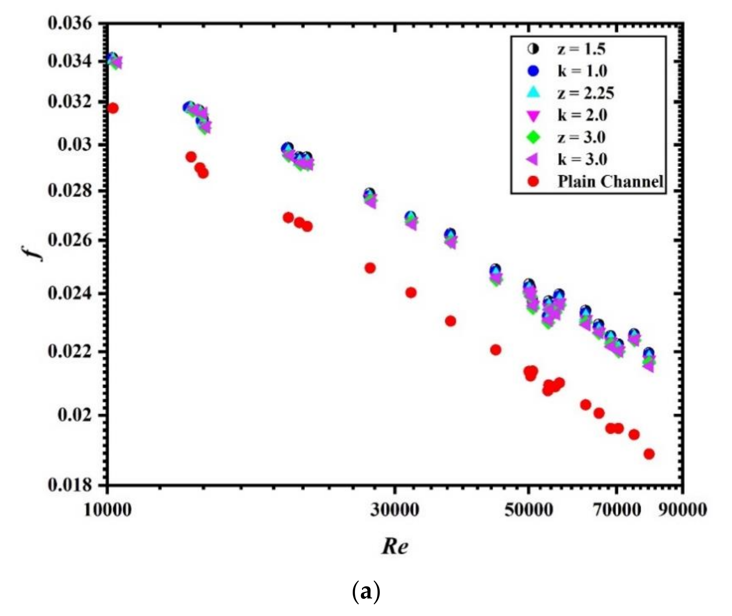
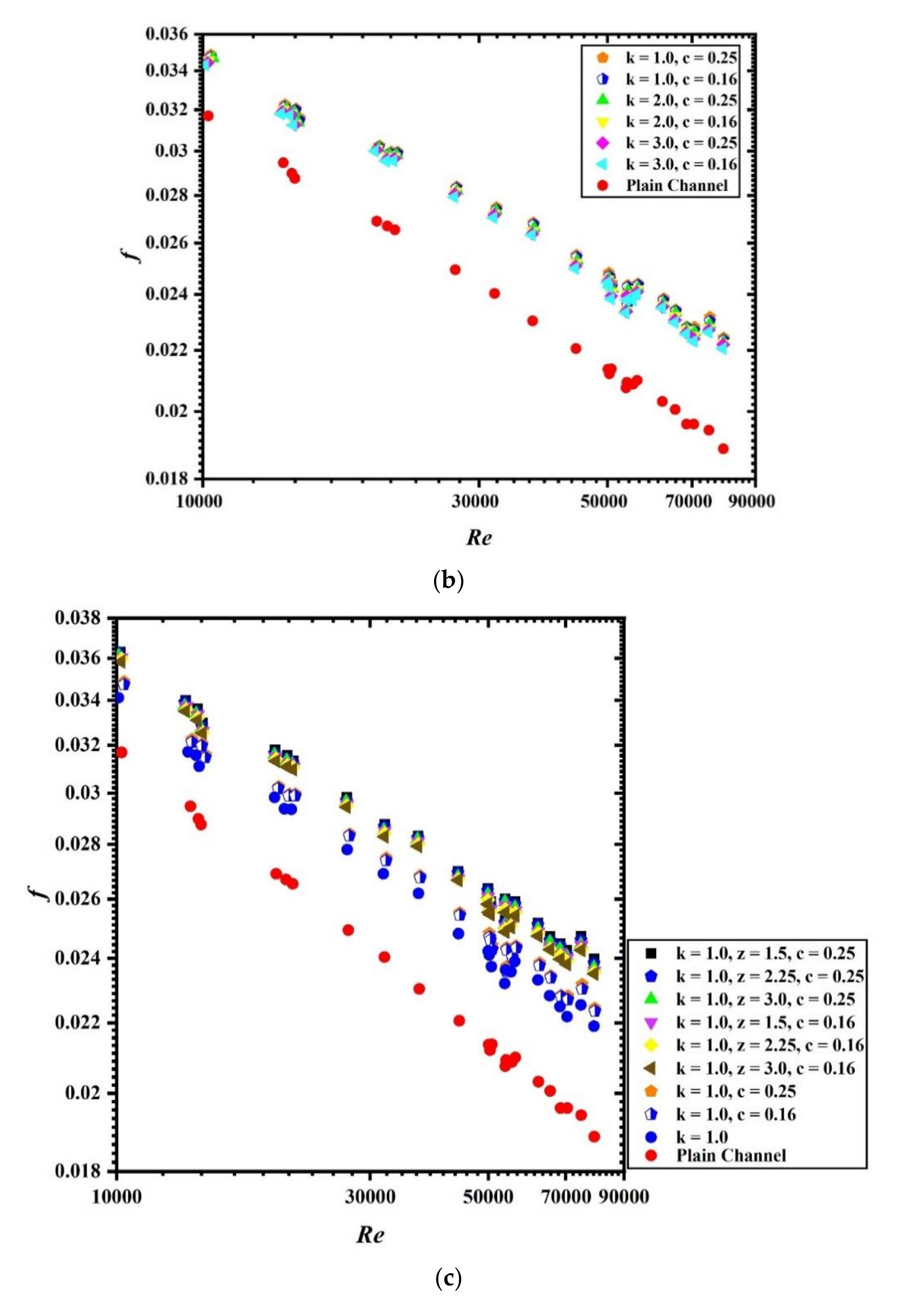
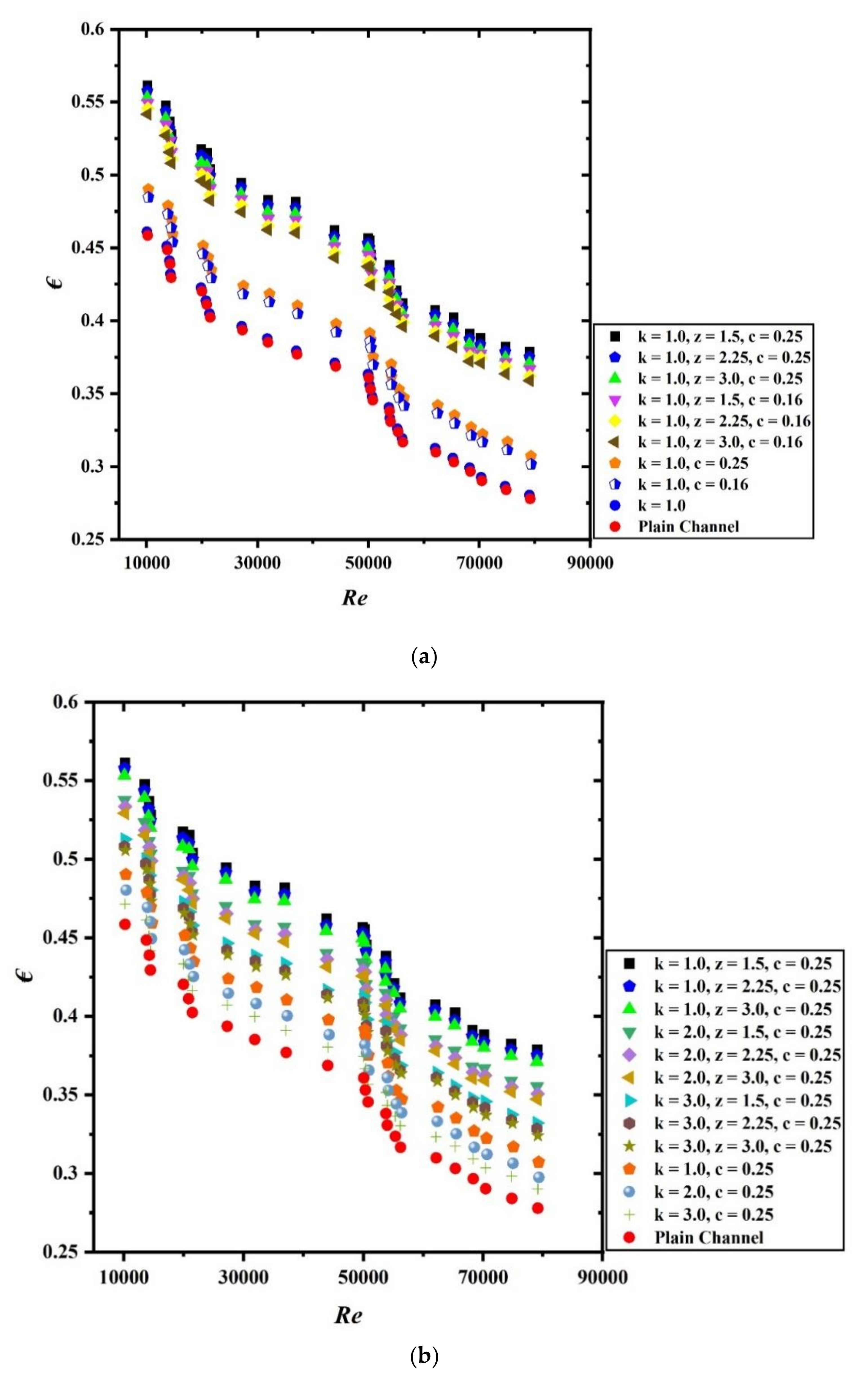
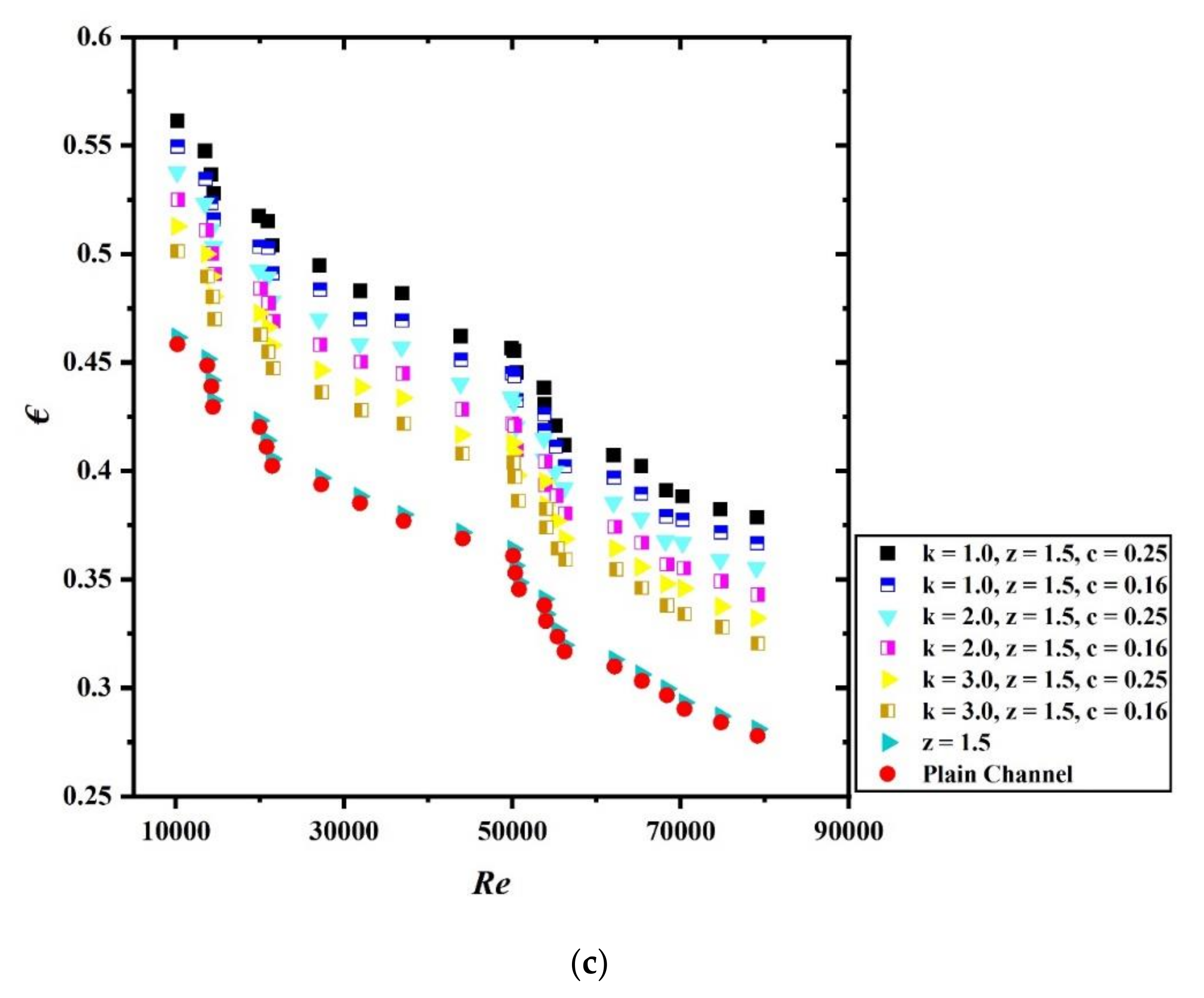
4.3. Influence of Hybrid Tapes on the Friction Factor

The thermal performance of thermal flow system also depends upon the friction factor. Higher friction factor results in low thermal performance. Hence, one should consider the frictional losses seriously. The presence of inserts in the flow field helps in the augmentation of heat transfer but it will also escalate the friction. The resulting pressure drop directly led to enhanced power for the same output. The various causes of pressure drop are enhanced contact between fluid and insert, reduction in dynamic pressure, formation of vortices in the flow field, etc. Figure 6a–e shows the alteration in friction factor (f) with Re for different combinations of configuration and parameters. As expected in the turbulent flow regime, friction factor shows a decreasing trend with increase in the Re.
Figure 6a shows that the plot for friction factor (f) is the function of Re for wavy tape and spring tape without groove acting alone, and the comparison is made with smooth tube data. Increase in friction factor is noticed for both types of tape with very negligible variations among the both the tapes for different wave ratio (z) and spring ratio (k).
Figure 6b shows the plot for friction factor with Re for grooved spring tapes of different spring ratio (k) and grooved depth ratio (c) acting alone. No significant enhancement in the friction factor has been noticed when results are compared with different configurations of parameters when tapes are acting alone for all Re.
Figure 6c shows the changes in friction factor values with Re for hybrid tapes with fixed spring ratio (k = 1.0), while other parameters vary. It is clearly visible from the graph that increase in friction factor is noticeable when compared with the results of grooved spring tapes and spring tape without groove. However, once again the variation in the value of friction factor for different combinations of hybrid tapes is negligible.
Figure 6d shows the variation of friction factor with Re for hybrid tape with fixed grooved depth ratio (c = 0.25), and different combinations of spring ratio (k) and wave ratio (z). Increase in friction factor is noticed with highest increase for the hybrid case having k = 1.0, z = 1.5, and c = 0.25 while the least friction factor has been noticed for k = 3.0, z = 3.0, and c = 0.25. It can be said that friction factor (f) decreases with increase in spring ratio as well as wave ratio when grooved depth ratio (c) is constant at 0.25. This trend is also clearly visible for the case of grooved spring tapes acting alone.
Figure 6e shows that the plot of friction factor for the case of hybrid tapes for the different combinations of spring ratio (k), wave ratio (z), and grooved depth ratio (c). The wave ratio (z) is kept constant at 1.5. Once again, the maximum friction factor is noticed for the hybrid tape having parameters of k = 1.0, z = 1.5, and c = 0.25. An increase in spring ratio results in a decreased friction factor.
Hence, from the above discussion, it is clear that friction factor shows a decreasing trend for increasing spring ratio (k), wave ratio (z) while increasing the grooved depth ratio (c) results in higher friction factor (f).

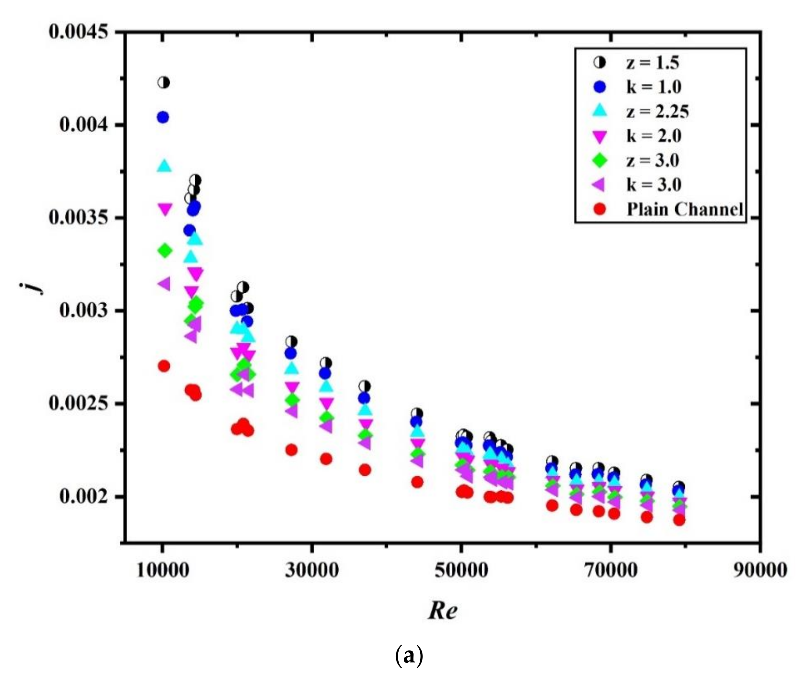
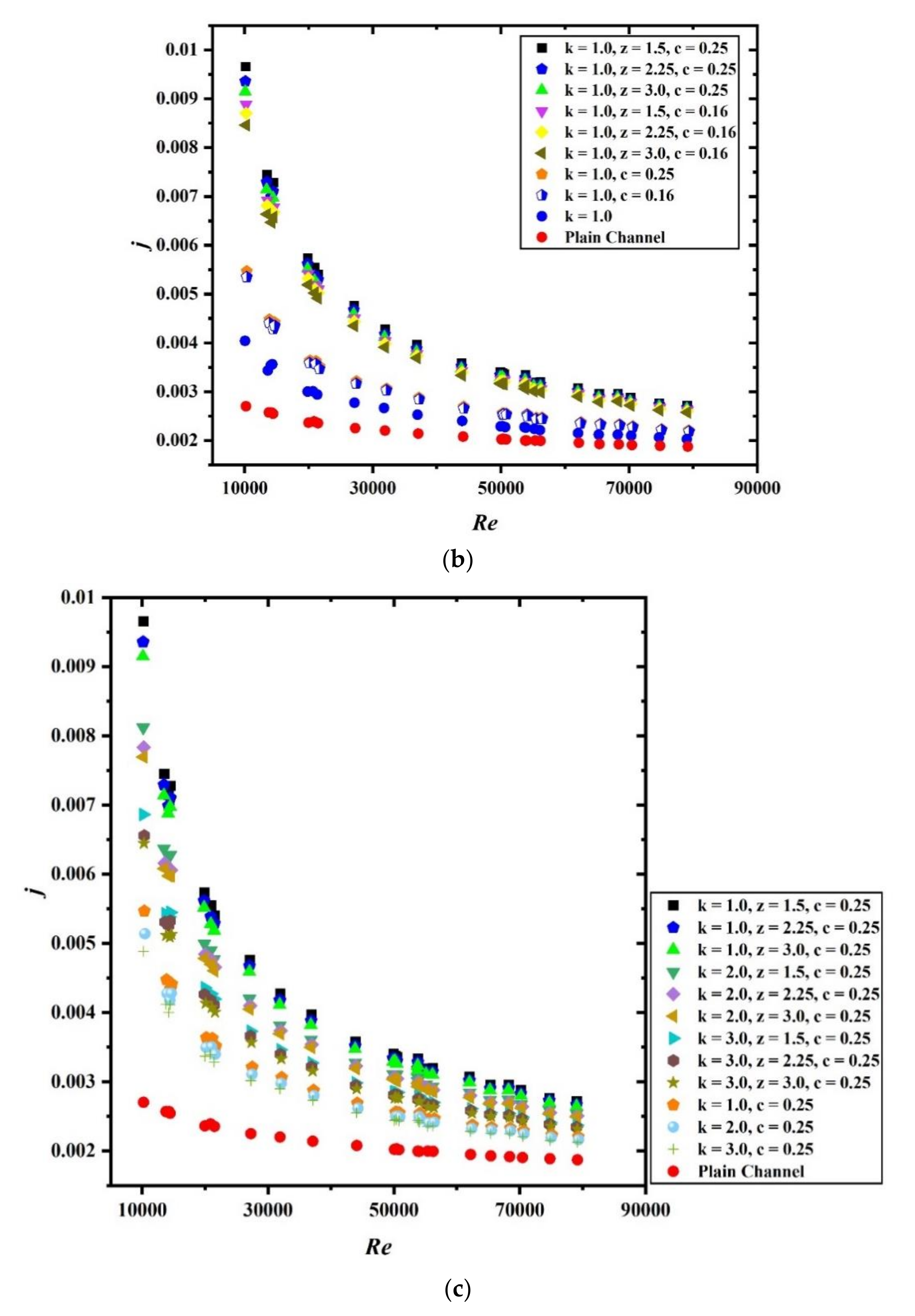
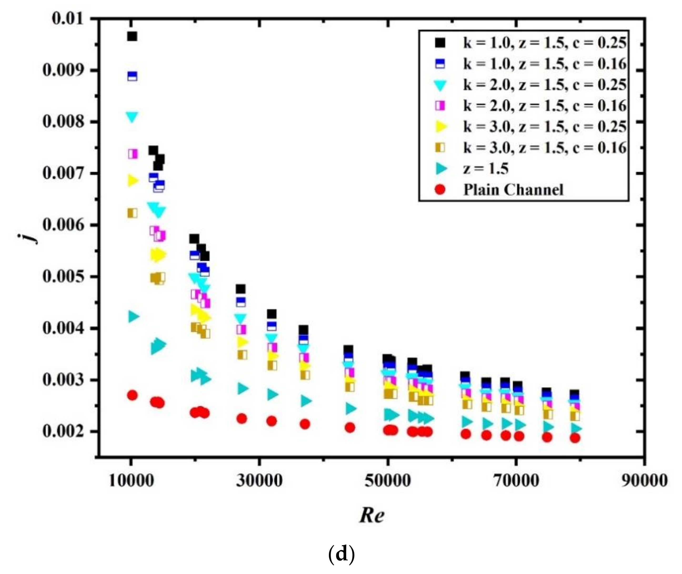
4.4. Influence of Hybrid Tapes on the Colburn J-Factor

Colburn j-factor is a non-dimension parameter that is used in convective heat transfer analysis which gives an analogy between heat, mass, and momentum transfer. Figure 7a–e shows the variation in the Colburn j-factor for different arrangements of tapes and parameter combinations. A diminishing trend has been noticed for Colburn j-factor with Re. The highest variation is noted at Re = 10,000, while the least variation was noticed very close to Re = 80,000 for all the configurations.
Figure 7a shows the plot representing the variation of j-factor with Re when the wavy tape and spring tape without groove act alone. The decreasing trend is prevalent in the plot where the highest value of Colburn j-factor is noticed for wavy tape having wave ratio (z) of 1.5 for all Re and is least noted for spring tape of spring ratio (k) 3.0.
Figure 7b shows the curve representing the variation of j-factor with Re for hybrid tapes keeping the spring ratio (k) constant at 1.0 and varying the other two parameters i.e., z and c. The j-factor is significantly higher for hybrid tape than spring tape and plain channel acting alone. It is also noted that at the beginning the values are quite high and slowly decrease with increasing Re. While considering hybrid tape only, the maximum deviation from beginning to end is noted for hybrid tape having parameters k = 1.0, z = 1.5, and c = 0.25 while the least deviation is noted for k = 1.0, z = 3.0, and c = 0.16.
Figure 7c shows the plot for Colburn j-factor variation with Re for hybrid tapes for constant grooved depth ratio (c) while varying the k and z, and similarly Figure 7d shows the plot for Colburn j-factor variation with Re for hybrid tapes for a fixed value of z while varying k and c. Once again it is observed from the figures that the highest value of j-factor is noted at the entrance which keeps gradually decreasing with increase in Re. It is clearly visible in the plot that hybrid tapes having lower spring ratio, wave ratio and higher grooved depth ratio shows the maximum improvement in the j-factor value while increasing the spring ratio and wave number leads to reduced value of j-factor.

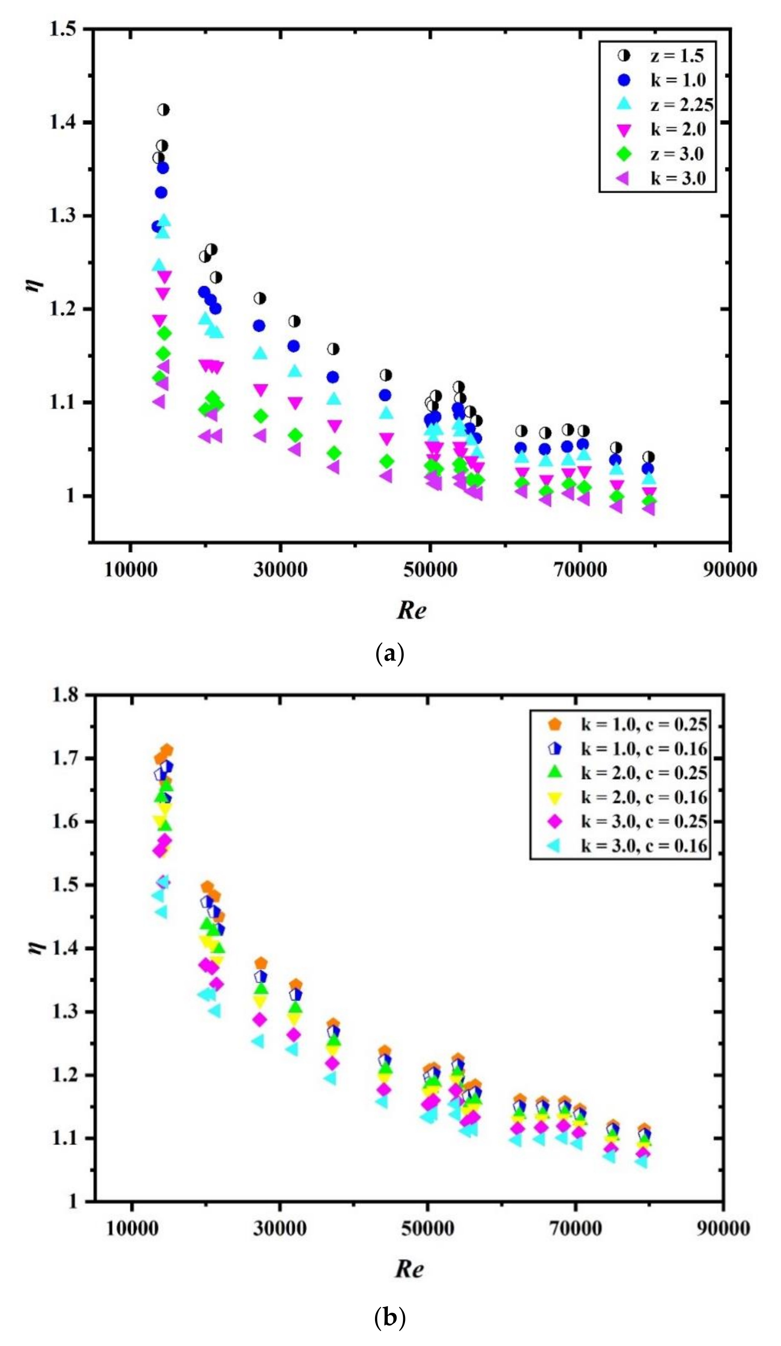
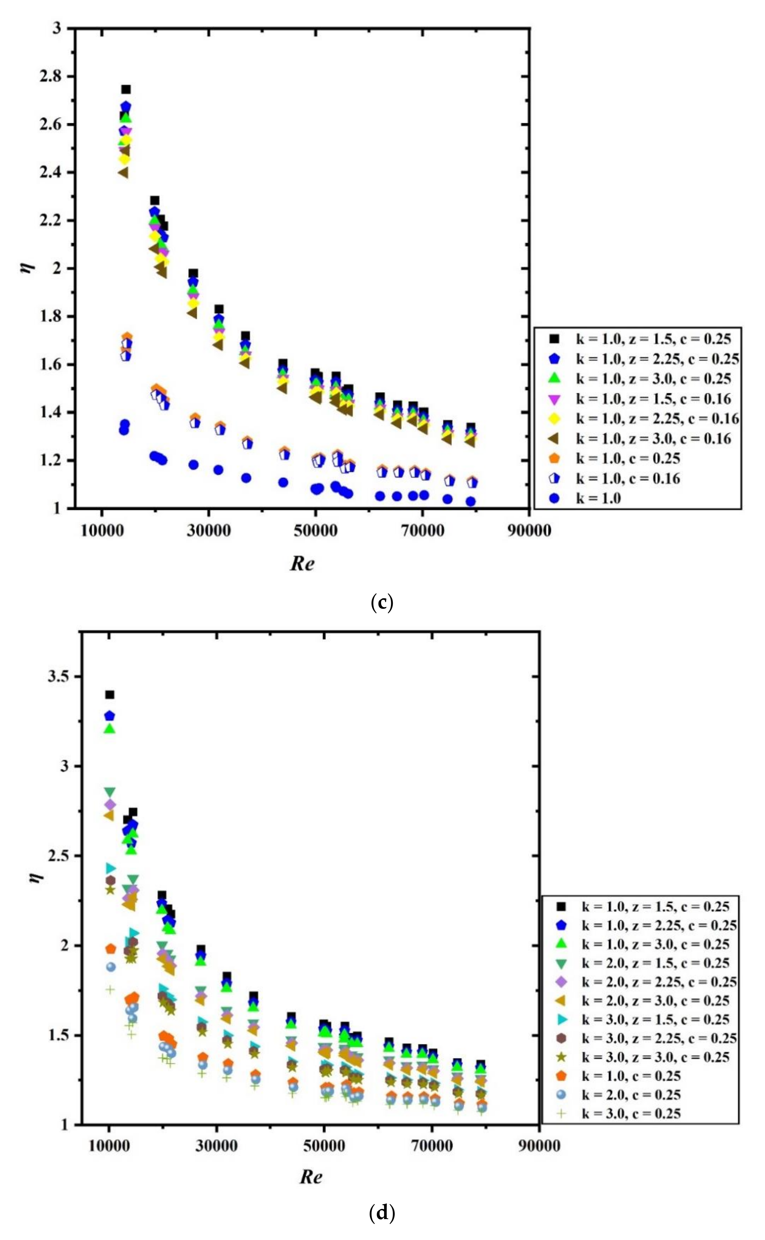
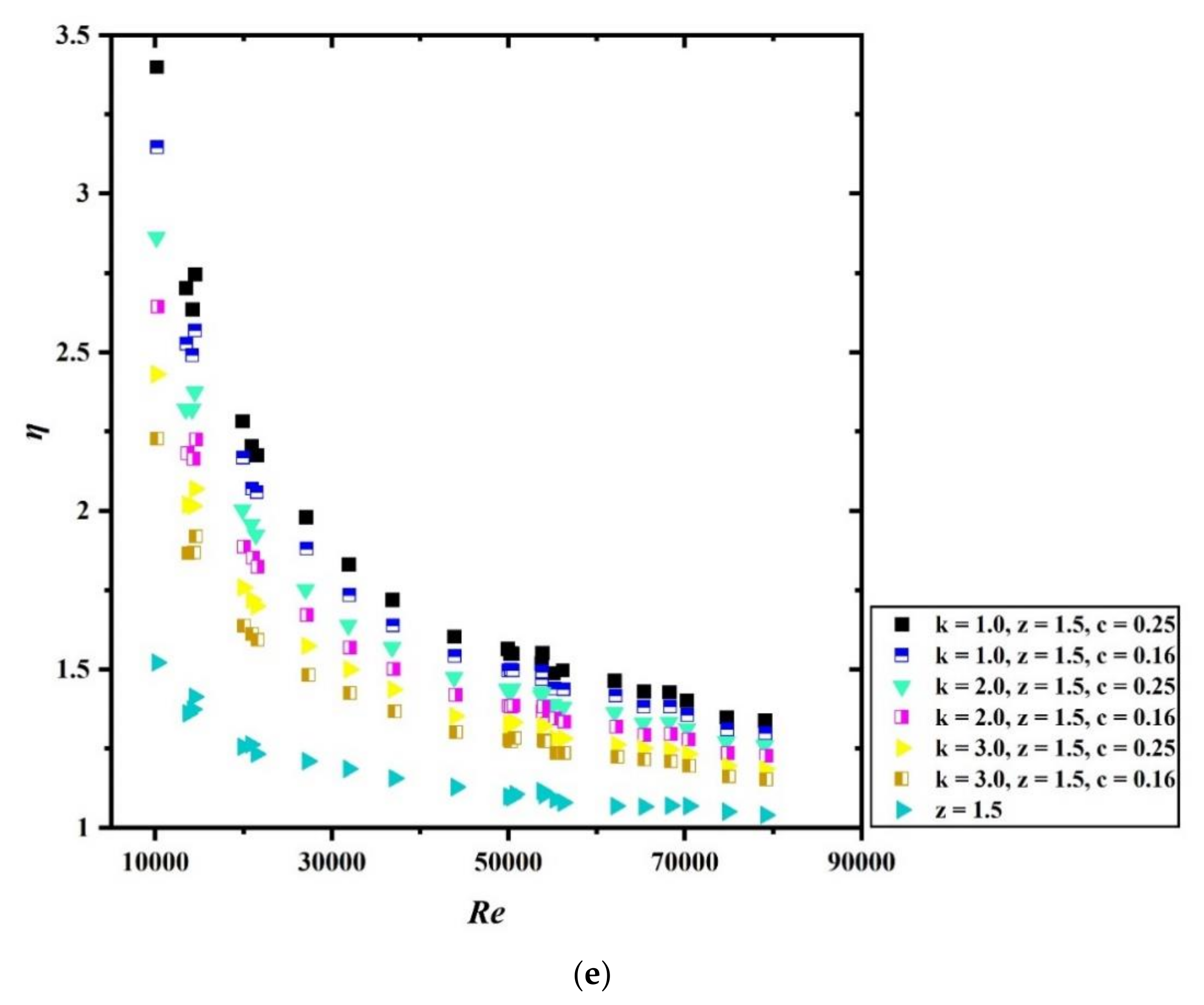
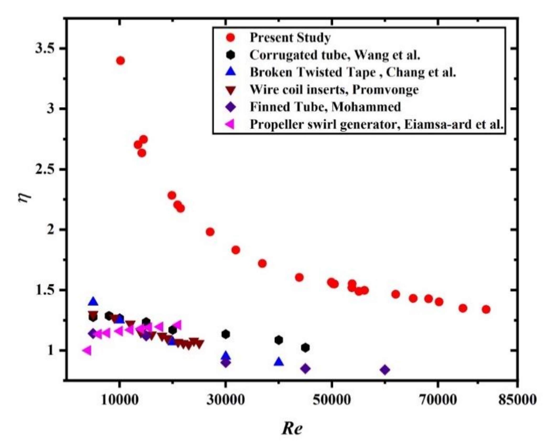
4.5. Influence of Thermo-Hydraulic Performance Factor

Thermo-hydraulic performance factor symbolized by ‘η’ is represented by Equation (12) and is defined as the balance of Nusselt number enhancement and friction factor enhancement. This factor is the best parameter to evaluate the actual enhancement in the thermal performance of a heat exchanger. Figure 8a–e shows the various plots for thermo-hydraulic performance with Re for different combinations of parameters.
Figure 8a shows the variation of thermo-hydraulic performance factor with Re when wavy tape and spring tape without groove acting alone in the fluid domain. It is clear from the graph that ‘η’ is above 1 for all the cases with highest value reported for wavy tape having wave ratio (z) of 1.5 while the least enhancement is noted for spring tape having spring ratio of 3.0. This is because the lesser gap between the spring increases the formation of vortices and secondary flow in the fluid domain and results in higher enhancement in heat transfer. At the same time, the friction factor is also enhanced due to an increase in the surface area of spring tape of the same length but it is not that dominant. These two factors are responsible for higher thermo-hydraulic performance.
Figure 8b represents the plot for the thermo-hydraulic performance factor variation with Re for groove spring tape of different configurations acting alone. Again, one can notice that the plot clearly shows that lower spring ratio along with higher grooved depth ratio results in higher thermo-hydraulic performance while the least enhancement is noted for spring tape having k = 3.0, and c = 0.16.
Figure 8c–e presented figures, which shows the variation of thermo-hydraulic performance factor as a function of Re for hybrid tapes with variation of z, k and c. In Figure 8c, the spring ratio is kept constant, for Figure 8d grooved depth ratio is kept fixed while for Figure 8e the wave ratio is kept constant. From all the above mentioned figures it is clearly interpreted that hybrid tape having parameter k = 1.0, z = 1.5 and c = 0.25 gives the highest values of η when compared with other combinations. Hence, it can be said that thermo-hydraulic performance factors decrease with the increase in spring ratio (k), increase in wave ratio (z) and decrease in grooved depth ratio (c).

4.6. Influence of Exergy Efficiency

Exergy efficiency analysis is done for the system to evaluate the energy conversion and distribution within the system. It is a thermodynamic process which helps in the detection of sources of thermal inefficiency within the system. Exergy analysis is based on the second law of thermodynamics, and it provides an idea about variation of the physical process with ideal process. Exergy efficiency () analysis also helps in removing the irreversibility associated with the system. Figure 9a–c gives details of exergy efficiency as a function of Re for a different combination of parameters for the hybrid tapes and are compared with exergy efficiency of spring tape with or without groove and wavy tape acting alone as well as plain channel. It is noticed from the figures that exergy efficiency remains significantly high for the hybrid tapes which is followed by other configurations studied. It is clearly visible for all the plots that hybrid tape having parameter k = 1.0, z = 1.5, and c = 0.25, shows the maximum exergy efficiency for all the values of Re. However, a decreasing trend is noticed for exergy efficiency with increase in the Re. From Figure 9a,c, it is clear that use of single tape without any grooves shows negligible variation in the exergy efficiency with plain channel while increasing the spring ratio (k), wave ratio (z) and decreasing the value of grooved depth ratio (c), resulting in decreased exergy efficiency.

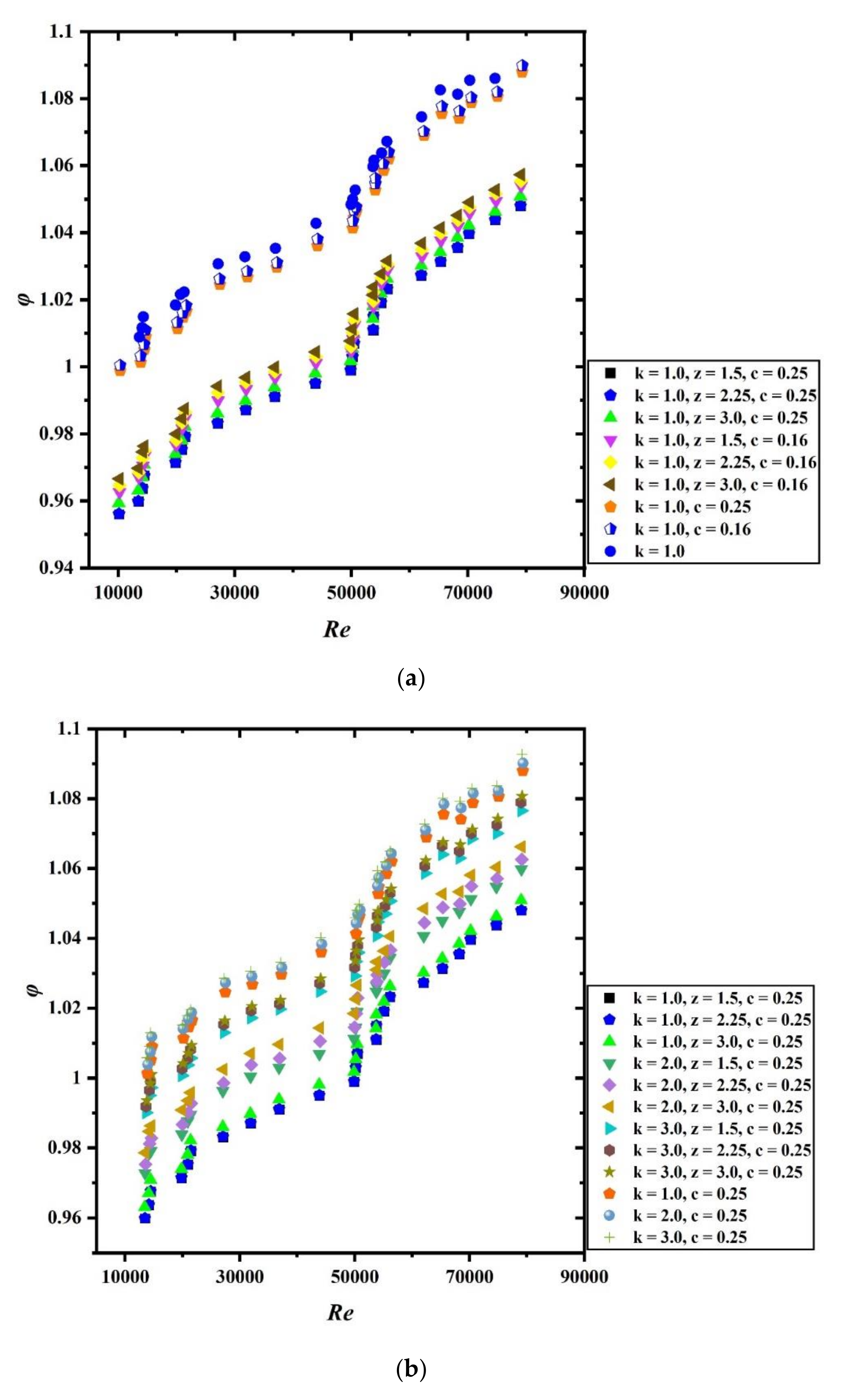
4.7. Influence of Irreversibility

Irreversibility occurs in the conduit due to heat transfer and pressure drop occurring in the duct. This is because of heat loss and friction losses that occurr in the flow process. Figure 10a–c shows the variation in the irreversibility factor ( φ ) with Re for various design specifications of tape inserts. Figure 10a–c clearly shows that irreversibility is highest when spring tapes without grooves act alone followed by grooved spring tapes followed by hybrid grooved tapes in the flow field. From the above discussion, it can be interpreted that the performance of heat transfer improved with the use of complex geometry. Additionally, with increase in the Re, the thermal performance improved which results in lower entropy generation. Higher temperature gradient and velocity gradient result in enhanced irreversibility of the system. For the present analysis and obtained graphs, we can say that the temperature gradient in the flow field becomes more subtle with the increase in the Re which results in a decrease in irreversibility while velocity gradient is enhanced with the increase in Re which results in more entropy generation.

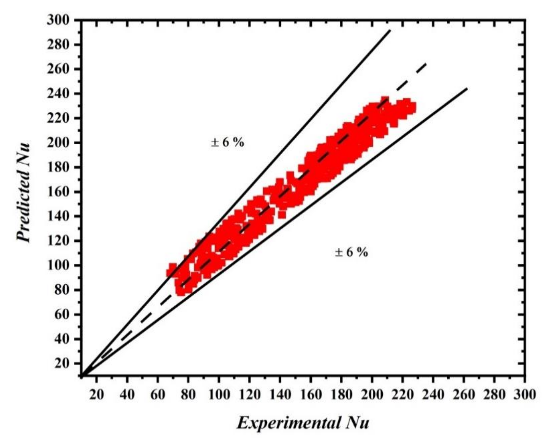
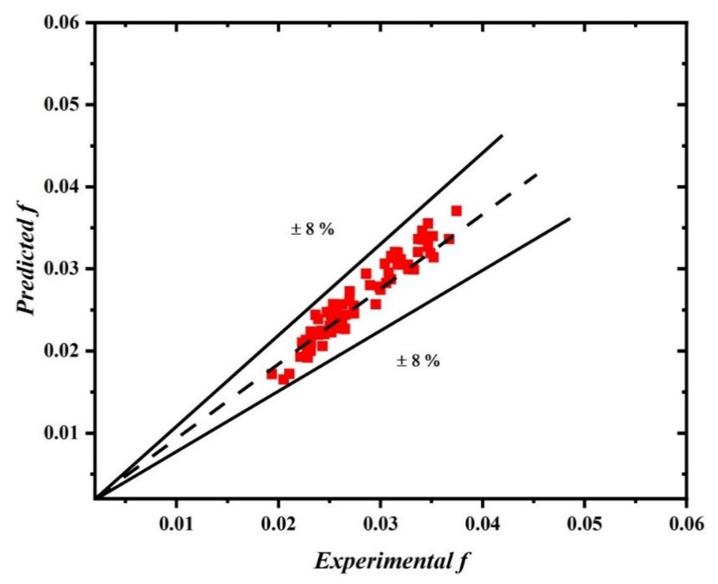
4.8. Correlations for Predicting the Nusselt Number and Friction Factor

The data obtained from the experimentation for the case of hybrid grooved tape shows strong influence of other parameters such as Re, Pr, spring ratio, wavy ratio, and grooved depth ratio. Hence, correlations for Nu and f are developed using experimental data through the regression analysis. Equation 19 and 20 shows the correlations for Nu and f for the case of hybrid grooved tape.
N u = 0.171   R e 0.801 k 0.221 z 0.069 c 0.01 P r 0.13
f = 1.401   R e 0.381 k 0.312 z 0.163 c 0.121
Figure 11 and Figure 12 show that the divergence between the experimentally gained and predicted data of Nu and f for hybrid grooved tape are ±6% and ±8%, respectively.

4.9. Comparability of Thermo-Hydraulic Performance of Present Investigation with Previous Articles

The thermo-hydraulic behaviour of the channel embedded with hybrid grooved tape with a spring ratio (k) of 1.0, wave ratio (z) of 1.5 and grooved depth ratio (c) of 0.25 is compared with previously investigated geometries, such as corrugated tube, broken twisted tape, finned ducts, propeller swirl generator and wire coil inserts [90,91,92,93,94]. The comparative plot with these geometries discussed by these researchers [90,91,92,93,94] is depicted in Figure 13. The present configuration offers improved performance over previously studied geometries. The graph clearly depicted that the other passive heat transfer enhancement methods show lower thermal performance when compared with present investigation. The various methods studied by different authors [90,91,92,93,94] for thermal enhancement show improvement in heat transfer, but the frictional losses associated with the design are higher which results in lower value of thermal performance factor. However, in the present investigation the enhancement in heat transfer is much better over the enhancement in frictional losses that occurred due to the introduction of hybrid tape, which led to higher thermal performance factor.

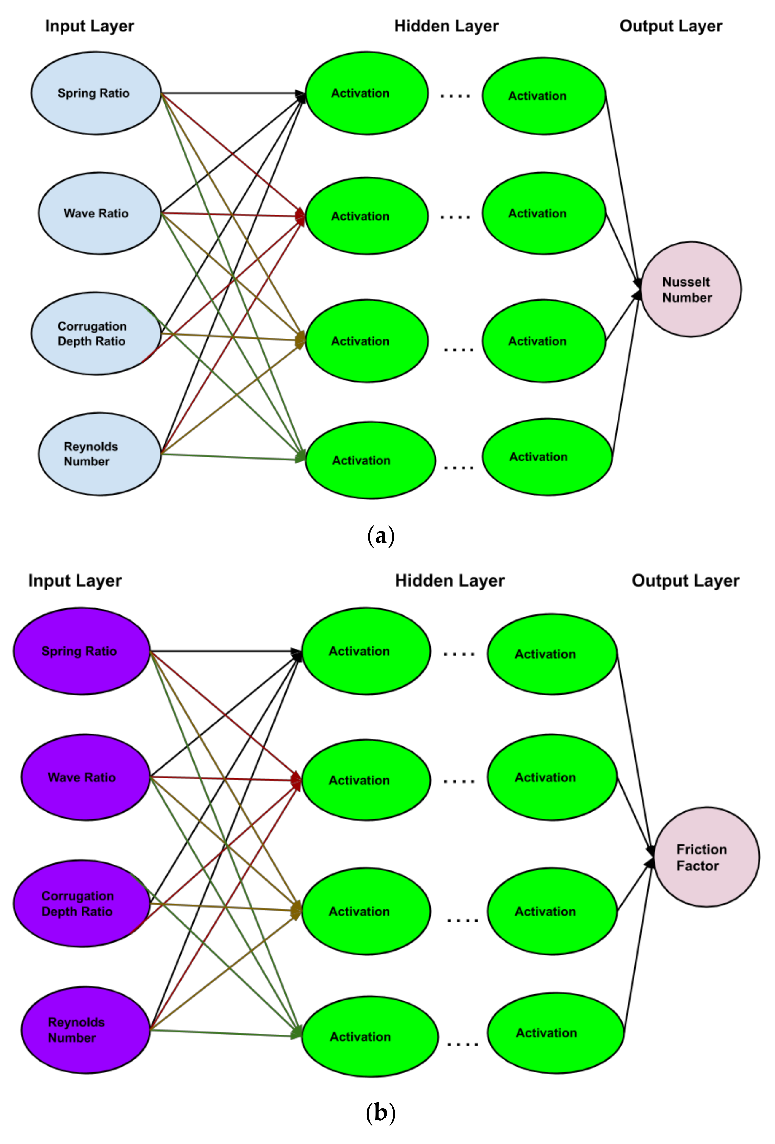
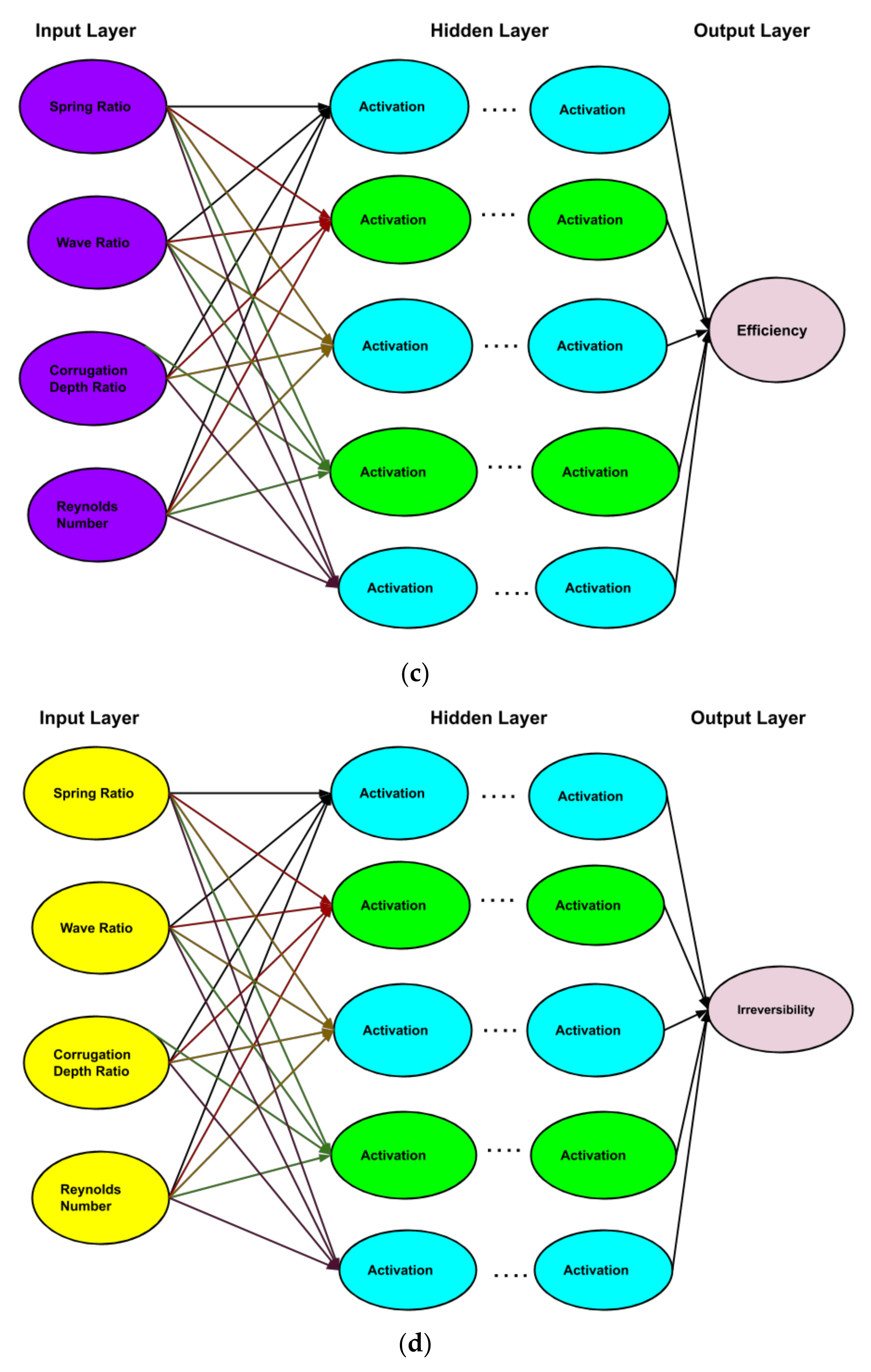
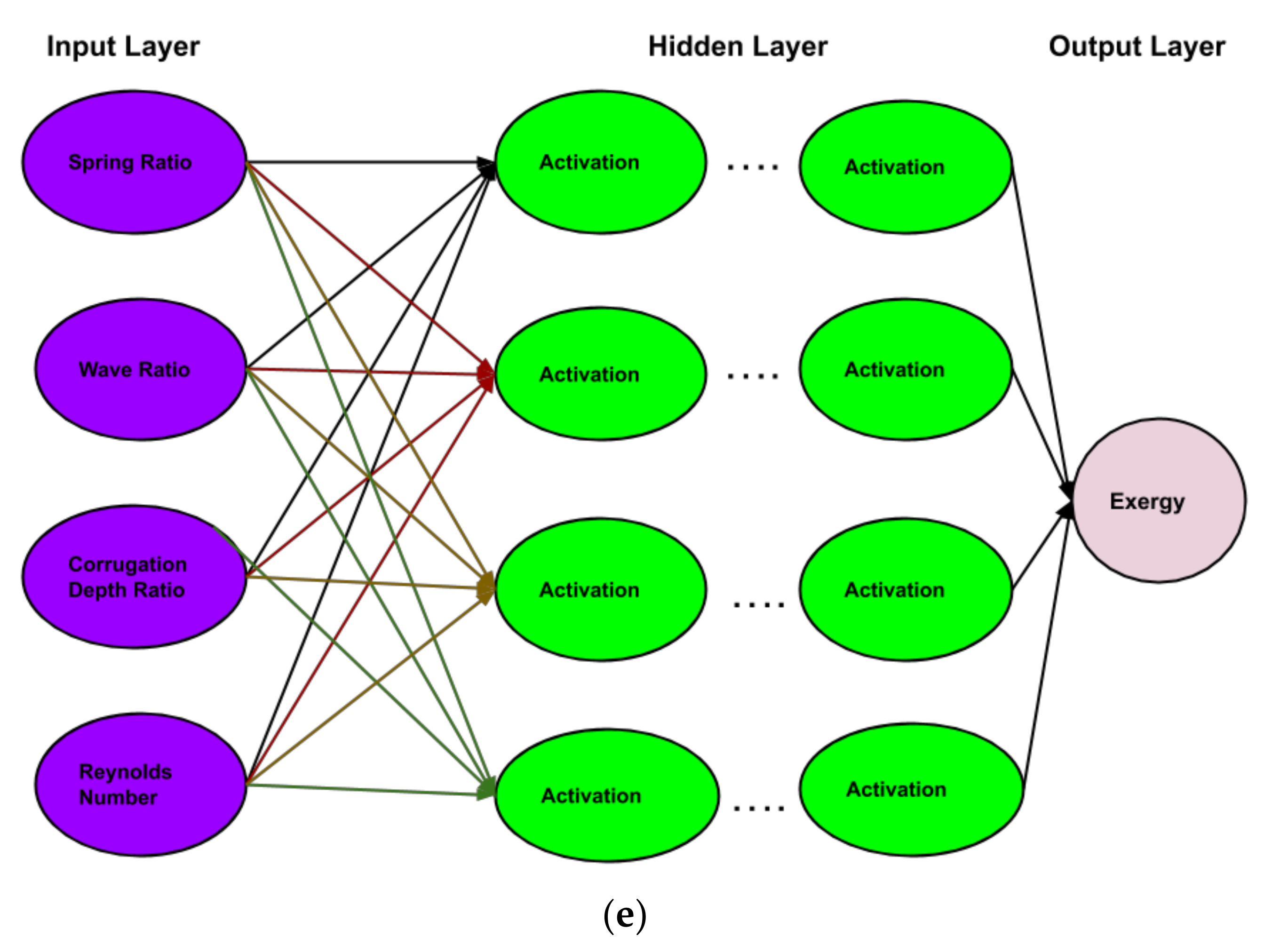
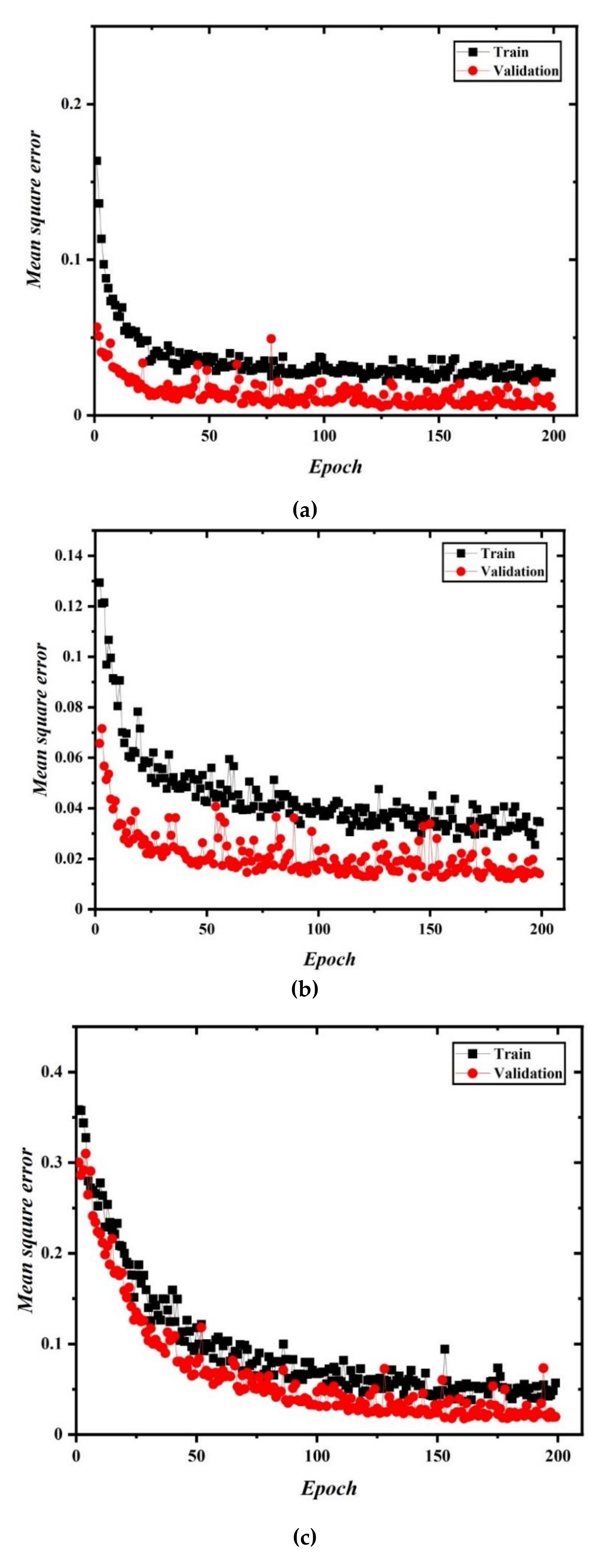
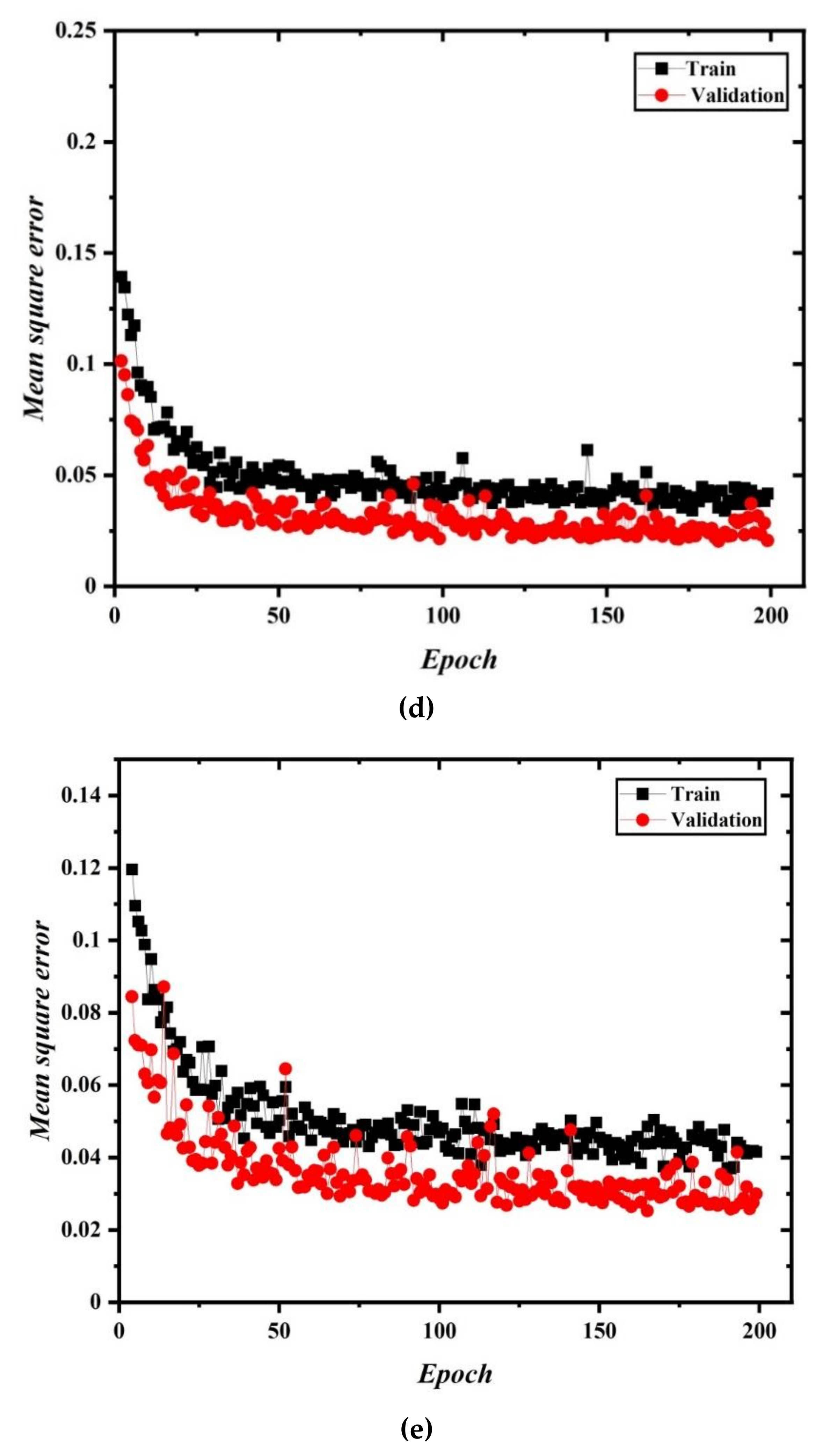
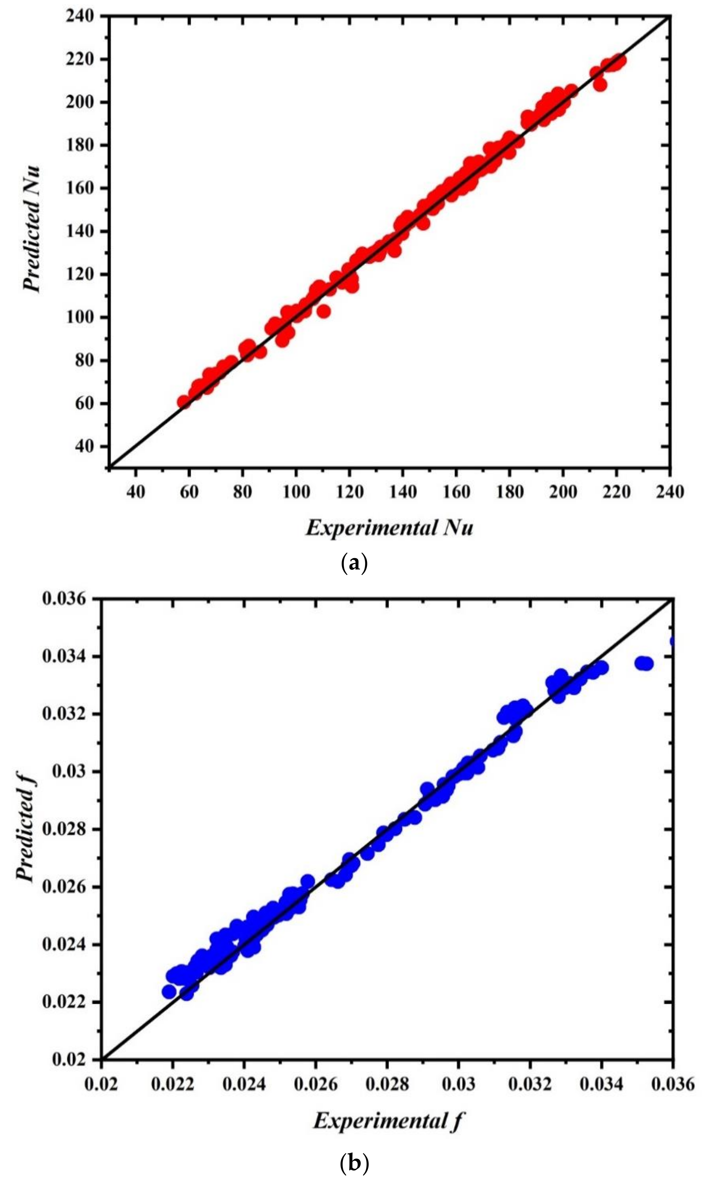
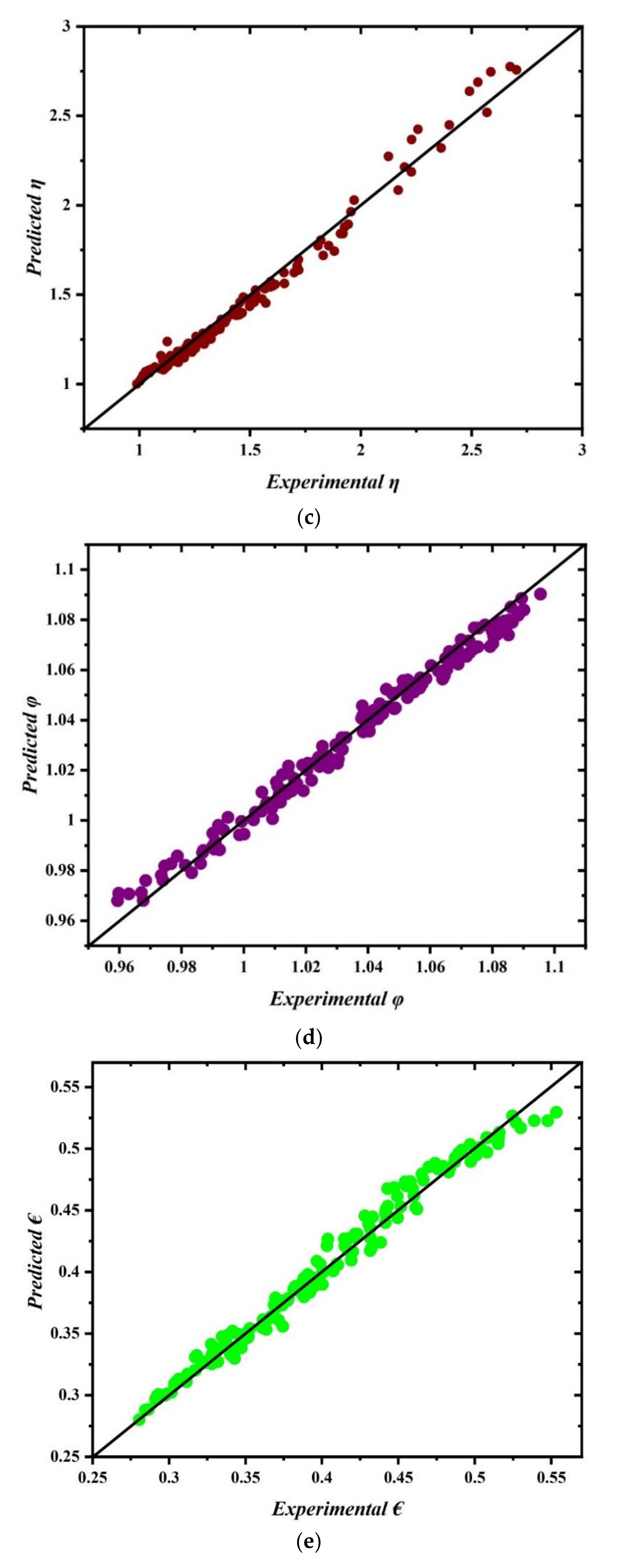
5. ANN-Based Heat Transfer Prediction

In this section, the influence of architectures [95] and their variants and training strategies are described exhaustively.
The basic working principle of ANN is as follows:
  • Forward Propagation:
    Take the inputs, multiply by the weights (just use random numbers as weights)
    Let Y = WiIi = W1I1+W2I2+W3I3.
    Pass the result of the input and the first three hidden layers through a ReLu activation function and the last hidden layer through a sigmoid formula to calculate the neuron’s output. The Sigmoid function is used to normalize the result between 0 and 1: 1/(1 + e−y).
    ReLu stands for Rectified Linear Units. The formula is deceptively simple: max(0,z). Despite its name and appearance, it is not linear and provides the same benefits as Sigmoid but with better performance. It can be written as: A(z) = z if z > 0 or A(z) = 0 if z ≤ 0.
  • Back Propagation
    Calculate the error, i.e., the difference between the actual output and the expected output. Depending on the error, adjust the weights by multiplying the error with the input and again with the gradient of the Sigmoid curve:
    Weight = Error Input Output (1-Output), here Output (1-Output) is derivative of sigmoid curve.
  • Repeat steps 1 and 2 until the model is trained to have a considerable minimal error on the training set.

5.1. Model

The primary step of the ANN-based approach is collecting the experimental data that is taken to train the model. Figure 14a,e demonstrates the architecture of the ANN-based approach for prediction.
The five layered neural network-based machine learning model is used to predict the Nusselt number, friction factor, thermodydraulic efficiency, irreversibility and exergy efficiency.
Mean square error (MSE) is calculated by taking the average of the square of the difference between the original and predicted values of the data.
MSE   =   1 N i = 1 n A c t u a l   v a l u e s P r e d i c t e d   v a l u e s 2
Here, N is the total number of observations/rows in the dataset.
MSE is one of the most commonly used metrics. It is most useful when the dataset contains outliers, or unexpected values (too high or too low values). Hence, this gives a good fit irrespective of any erroneous data available in the dataset.
The test accuracy is being shown in Table 1. The neural network is trained by taking batch size as 12 and epoch size as 200. The change in training and validation loss with an increase in epoch numbers is shown in Figure 15a–e.

5.2. Computational Environment

All the experiments were run on Google Colab Notebook with Nvidia GPU version 1.4.0-enabled and Keras 2.4.0 is used as an API to train and test the neural network models, thus favoring a way to clone hardware configuration. The best model is reported after experimenting many times with different configuration of the models.

5.3. Predictions Using ANN

Figure 16a–e shows the assessment between the predicted and actual experimental value of the test data for Nu, f, η, irreversibility and exergy efficiency, respectively. From the figures, one can understand that the ANN model fits the dataset acceptably. The performance of the models has reported an accuracy of more than 98.5% on the test dataset.
The detailed statistical analysis of the generated data is shown in Table 2 which includes a count of the data, mean, and standard deviation that elaborates the range or the distribution of the generated data.
The newly generated parameters for prediction are shown in Table 3. The Nusselt number, friction factor, thermohydraulic efficiency, irreversibility and exergy efficiency results of generated data are shown in Appendix A. The inputs are new to the model and hence the accuracy is measured to their outcomes. The present model for Nu, f, η, irreversibility and exergy efficiency will ease a very huge workload by determining the required outputs. With given test data as mentioned in the Appendix A, the researchers working with a similar experimental setup will get help to tune their parameters according to their needs and get their required result. It is important to note and consider an error factor of ±2–3% while considering the results.

6. Conclusions

The experiment was conducted to investigate the thermal performance of a circular channel with hybrid grooved tape inserts. For the study the following inferences were drawn:
  • An enhancement in Nu is recorded with an increment of Re for all the cases.
  • Among the hybrid grrod tape the highest HT is noted for k = 1.0, z = 1.5 and c = 0.25, while k = 3.0, z = 3.0 and c = 0.16 gives the minimum HT. As expected, a smooth plain tube has the lowest thermal energy transport coefficient.
  • The HT is found to rise with an increased grooved depth ratio (c). Likewise, average Nu declines with rise in spring ratio and wave ratio.
  • An ANN model is used for regression analysis to predict the HT, PD, thermohydraulic efficiency, irreversibility and exergy efficiency.
  • The models are evaluated to have an accuracy of 98.00% on unknown test data and the proposed model was able to reasonably forecast the Nu, f, η, irreversibility and exergy efficiency.
  • The results obtained from the analysis can be conveniently used to design highly efficient tube type heat exchangers.
  • From the above results, it is concluded that the use of hybrid grooved tape is proven to be an effective technique to enhance the thermal energy transport coefficient.

Author Contributions

Supervision: S.B.; M.S.; Writing—review & editing: S.B.; M.S.; Project administration: S.B.; Investigation: S.B.; D.K.V.; S.C.; R.R.; data curation: D.K.V.; S.C.; R.R.; A.I.; Writing: D.K.V.; S.C.; R.R.; Methodology: S.C.; R.R.; A.I.; Conceptualization: S.C.; R.R.; A.I. All authors have read and agreed to the published version of the manuscript.

Funding

RIG Grant, BITS Pilani.

Institutional Review Board Statement

Not applicable.

Informed Consent Statement

Not applicable.

Data Availability Statement

Data sharing not applicable.

Acknowledgments

The authors would like to shows their gratitude towards MCKVIE and BITS Pilani, Pilani Campus, (RIG Grant) for their constant support over the course of this experimental assessment.

Conflicts of Interest

The authors declare no conflict of interest.

Nomenclature

List of Symbols
CpSpecific heat of air
ddiameter of hole
DInner diameter of duct
Doouter diameter of the tube
ExinExergy rate at inlet
ExoutExergy rate at outlet
ExwExergy rate at wall
fFriction factor
HPerforation ratios
hHeat transfer Coefficient
ICurrent flow
jColburn j-factor
kthermconductivity of working fluid
kBrassThermal Conductivity of Brass
LLength of duct
mmass flow rate of air
Nsdimensionless entropy generation number
NuNusselt number
Ppitch ratios
PrPrandtl number
QHeat flow rate of air
QeElectrical power
qwwall heat flux
ReReynolds numbers
Rwthermal resistance due to the tube thickness
Sgenentropy generation
TbBulk temperature
TiInlet temperature
ToOutlet temperature
Towinner wall temperature
Twouter wall temperature
VVelocity of flow
VVoltage
yPitch of baffles
List of Special Symbols
αAngles of attack
ɳThermo-hydraulic performance factor
ϕirreversibility factor
ηExExergy efficiency
μDynamic vicosity
ρDensity of fluid

Appendix A

Table A1. Predicted result on Nu, f, €, ϕ, and η on generated data at minimum constant wave ration and groove depth ratio.
Sl. N0.kzcReNufϕη
13.51.250.115,00074.944490.0278965290.40495991.02553611.10463
23.251.250.115,00076.197030.0279413850.407688381.01201831.1171222
32.751.250.115,00078.596040.0279669460.41059161.00757381.1432143
42.51.250.115,00079.681810.0279935080.412753131.00642261.1568829
52.251.250.115,00082.451610.0280096330.414335461.00320041.1709807
61.51.250.115,00080.61540.0280297530.416033150.990713661.2137918
70.751.250.115,00082.784610.028037020.416879860.9793631.2509365
80.51.250.115,00082.905050.0280400160.417089460.97584111.2615612
93.51.250.130,000105.91420.0251633320.362116871.06528021.0604417
103.251.250.130,000107.56960.0252054870.36417131.05367841.0711048
112.751.250.130,000110.53260.0252758130.366207541.04945151.0930823
122.51.250.130,000111.73360.0253039540.367962331.04509041.1043295
132.251.250.130,000112.73290.0253040570.369032171.03138521.1157868
141.51.250.130,000114.63860.0253216270.37056781.02733251.1512022
150.751.250.130,000114.86470.025325650.371257281.01759851.1816947
160.51.250.130,000114.960.025349320.371377651.01320231.1904317
173.51.250.170,000181.93110.021891660.268128451.07612871.0109086
183.251.250.170,000183.42930.0219419920.26947461.0623481.0195662
192.751.250.170,000185.94240.0220346940.271996951.05916591.03712
202.51.250.170,000186.97620.0220773760.272909461.04262081.0461874
212.251.250.170,000187.86390.0221179330.273121361.037781.0554726
221.51.250.170,000189.71140.02222860.273844061.02041021.083682
230.751.250.170,000190.44560.0223094080.274057841.01738151.0944406
240.51.250.170,000190.77360.022329280.275246981.015182241.1138793
Table A2. Predicted result on Nu, f, €, ϕ, and η on generated data at maximum constant wave ration and groove depth ratio.
Sl. N0.kzcReNufϕη
13.53.250.2815,00099.145390.0284231360.44123191.03146341.4302515
23.253.250.2815,000103.41870.0285443640.447559151.02728191.4734231
32.753.250.2815,000112.170.0287969840.45974981.01931821.5643141
42.53.250.2815,000116.61630.0289291440.465593641.01557531.61111
52.253.250.2815,000121.10640.0290656720.471255721.01195311.6580449
61.53.250.2815,000134.76150.029503410.487306181.0018071.8017614
70.753.250.2815,000148.15410.029976670.50218090.99282951.9442455
80.53.250.2815,000152.42430.0301420820.50657950.99012811.9921432
93.53.250.2830,000130.86340.025856340.3994071.0703811.271512
103.253.250.2830,000135.64210.0259709060.40557451.06714261.2995856
112.753.250.2830,000145.24350.0262004730.417691681.0607421.3594307
122.53.250.2830,000150.01740.0263164530.423650861.05746571.391301
132.253.250.2830,000154.72540.0264332930.42965021.05411341.424515
141.53.250.2830,000168.17730.026787570.44774411.04374871.5285946
150.753.250.2830,000180.53640.0271434840.465191421.03311351.6262425
160.53.250.2830,000184.34890.0272636730.470455771.02964151.6559497
173.53.250.2870,000205.44110.0227583520.301902831.08650981.0828294
183.253.250.2870,000209.78590.0228728820.306535841.07906271.1008663
192.753.250.2870,000218.17510.0231032610.316053871.07676211.1384834
202.53.250.2870,000222.2170.0232188930.320940881.073922931.1582022
212.253.250.2870,000226.15460.0233350730.325921861.06622081.1785398
221.53.250.2870,000237.26120.023688080.341423421.06086061.2429912
230.753.250.2870,000246.80870.0240466630.35768441.05660781.308757
240.53.250.2870,000249.60420.024161030.363222331.04758051.330574

References

  1. Giwa, S.O.; Sharifpur, M.; Meyer, J.P. Effects of uniform magnetic induction on heat transfer performance of aqueous hybrid ferrofluid in a rectangular cavity. Appl. Therm. Eng. 2020, 170, 115004. [Google Scholar] [CrossRef]
  2. Joubert, J.C.; Sharifpur, M.; Solomon, A.B.; Meyer, J.P. Enhancement in heat transfer of a ferrofluid in a differentially heated square cavity through the use of permanent magnets. J. Magn. Magn. Mater. 2017, 443, 149–158. [Google Scholar] [CrossRef]
  3. Mahdavi, M.; Sharifpur, M.; Meyer, J.P. Implementation of diffusion and electrostatic forces to produce a new slip velocity in the multiphase approach to nanofluids. Powder Technol. 2017, 307, 153–162. [Google Scholar] [CrossRef] [Green Version]
  4. Adio, S.A.; Sharifpur, M.; Meyer, J.P. Influence of ultrasonication energy on the dispersion consistency of Al2O3–glycerol nanofluid based on viscosity data, and model development for the required ultrasonication energy density. J. Exp. Nanosci. 2016, 11, 630–649. [Google Scholar] [CrossRef] [Green Version]
  5. Bhattacharyya, S.; Chattopadhyay, H.; Bandyopadhyay, S.; Roy, S.; Pal, A.P.; Bhattacharjee, S. Experimental investigation on heat transfer enhancement by swirl generators in a solar air heater duct. Int. J. Heat Technol. 2016, 34, 191–196. [Google Scholar] [CrossRef]
  6. Yao, G.; Yang, H.; Zhao, J.; Wen, D. Experimental study on flow and heat transfer enhancement by elastic instability in swirling flow. Int. J. Therm. Sci. 2020, 157, 106504. [Google Scholar] [CrossRef]
  7. Thianpong, C.; Eiamsa-ard, P.; Wongcharee, K.; Eiamsa-ard, S. Compound heat transfer enhancement of a dimpled tube with a twisted tape swirl generator. Int. Commun. Heat Mass Transf. 2009, 36, 698–704. [Google Scholar] [CrossRef]
  8. Sheikholeslami, M.; Gorji-Bandpy, M.; Ganji, D.D. Review of heat transfer enhancement methods: Focus on passive methods using swirl flow devices. Renew. Sustain. Energy Rev. 2015, 49, 444–469. [Google Scholar] [CrossRef]
  9. Eiamsa-ard, S.; Promvonge, P. Enhancement of heat transfer in a tube with regularly-spaced helical tape swirl generators. Sol. Energy 2005, 78, 483–494. [Google Scholar] [CrossRef]
  10. Das, B.; Mondol, J.D.; Debnath, S.; Pugsley, A.; Smyth, M.; Zacharopoulos, A. Effect of the absorber surface roughness on the performance of a solar air collector: An experimental investigation. Renew. Energy 2020, 152, 567–578. [Google Scholar] [CrossRef]
  11. Yadav, S.; Kaushal, M.; Varun; Siddhartha. Nusselt number and friction factor correlations for solar air heater duct having protrusions as roughness elements on absorber plate. Exp. Therm. Fluid Sci. 2013, 44, 34–41. [Google Scholar] [CrossRef]
  12. Alammar, A.A.; Al-Mousawi, F.N.; Al-Dadah, R.K.; Mahmoud, S.M.; Hood, R. Enhancing thermal performance of a two-phase closed thermosyphon with an internal surface roughness. J. Clean. Prod. 2018, 185, 128–136. [Google Scholar] [CrossRef]
  13. Soontarapiromsook, J.; Mahian, O.; Dalkilic, A.S.; Wongwises, S. Effect of surface roughness on the condensation of R-134a in vertical chevron gasketed plate heat exchangers. Exp. Therm. Fluid Sci. 2018, 91, 54–63. [Google Scholar] [CrossRef]
  14. Prakash, C.; Saini, R.P. Heat transfer and friction in rectangular solar air heater duct having spherical and inclined rib protrusions as roughness on absorber plate. Exp. Heat Transf. 2019, 32, 469–487. [Google Scholar] [CrossRef]
  15. Nilpueng, K.; Keawkamrop, T.; Ahn, H.S.; Wongwises, S. Effect of chevron angle and surface roughness on thermal performance of single-phase water flow inside a plate heat exchanger. Int. Commun. Heat Mass Transf. 2018, 91, 201–209. [Google Scholar] [CrossRef]
  16. Giwa, S.O.; Sharifpur, M.; Meyer, J.P. Experimental study of thermo-convection performance of hybrid nanofluids of Al2O3-MWCNT/water in a differentially heated square cavity. Int. J. Heat Mass Transf. 2020, 148, 119072. [Google Scholar] [CrossRef]
  17. Mansoury, D.; Doshmanziari, F.I.; Kiani, A.; Chamkha, A.J.; Sharifpur, M. Heat Transfer and Flow Characteristics of Al2O3/Water Nanofluid in Various Heat Exchangers: Experiments on Counter Flow. Heat Transf. Eng. 2020, 41, 220–234. [Google Scholar] [CrossRef]
  18. Osman, S.; Sharifpur, M.; Meyer, J.P. Experimental investigation of convection heat transfer in the transition flow regime of aluminium oxide-water nanofluids in a rectangular channel. Int. J. Heat Mass Transf. 2019, 133, 895–902. [Google Scholar] [CrossRef] [Green Version]
  19. Mahdavi, M.; Garbadeen, I.; Sharifpur, M.; Ahmadi, M.H.; Meyer, J.P. Study of particle migration and deposition in mixed convective pipe flow of nanofluids at different inclination angles. J. Therm. Anal. Calorim. 2019, 135, 1563–1575. [Google Scholar] [CrossRef]
  20. Sharifpur, M.; Solomon, A.B.; Ottermann, T.L.; Meyer, J.P. Optimum concentration of nanofluids for heat transfer enhancement under cavity flow natural convection with TiO2—Water. Int. Commun. Heat Mass Transf. 2018, 98, 297–303. [Google Scholar] [CrossRef]
  21. Mahdavi, M.; Sharifpur, M.; Meyer, J.P. Discrete modelling of nanoparticles in mixed convection flows. Powder Technol. 2018, 338, 243–252. [Google Scholar] [CrossRef]
  22. Zaboli, M.; Nourbakhsh, M.; Ajarostaghi, S.S.M. Numerical evaluation of the heat transfer and fluid flow in a corrugated coil tube with lobe-shaped cross-section and two types of spiral twisted tape as swirl generator. J. Therm. Anal. Calorim. 2020. [Google Scholar] [CrossRef]
  23. Yang, L.; Han, H.; Li, Y.; Li, X. A Numerical Study of the Flow and Heat Transfer Characteristics of Outward Convex Corrugated Tubes with Twisted-Tape Insert. J. Heat Transfer. 2016, 138, 024501. [Google Scholar] [CrossRef]
  24. Bhattacharyya, S.; Benim, A.C.; Chattopadhyay, H.; Banerjee, A. Experimental investigation of heat transfer performance of corrugated tube with spring tape inserts. Exp. Heat Transf. 2019, 32, 411–425. [Google Scholar] [CrossRef]
  25. Bhattacharyya, S.; Vishwakarma, D.K.; Soni, M.K. Heat Transfer and Pressure Drop in Transitional Flow: A Short Review. IOP Conf. Ser. Mater. Sci. Eng. 2021, 1080, 012050. [Google Scholar] [CrossRef]
  26. Kazemi Moghadam, H.; Mousavi Ajarostaghi, S.S.; Poncet, S. Extensive numerical analysis of the thermal performance of a corrugated tube with coiled wire. J. Therm. Anal. Calorim. 2020, 140, 1469–1481. [Google Scholar] [CrossRef]
  27. Pethkool, S.; Eiamsa-ard, S.; Kwankaomeng, S.; Promvonge, P. Turbulent heat transfer enhancement in a heat exchanger using helically corrugated tube. Int. Commun. Heat Mass Transf. 2011, 38, 340–347. [Google Scholar] [CrossRef]
  28. Wang, W.; Zhang, Y.; Li, Y.; Han, H.; Li, B. Numerical study on fully-developed turbulent flow and heat transfer in inward corrugated tubes with double-objective optimization. Int. J. Heat Mass Transf. 2018, 120, 782–792. [Google Scholar] [CrossRef]
  29. T’Joen, C.; Jacobi, A.; De Paepe, M. Flow visualisation in inclined louvered fins. Exp. Therm. Fluid Sci. 2009, 33, 664–674. [Google Scholar] [CrossRef]
  30. Lyman, A.C.; Stephan, R.A.; Thole, K.A.; Zhang, L.W.; Memory, S.B. Scaling of heat transfer coefficients along louvered fins. Exp. Therm. Fluid Sci. 2002, 26, 547–563. [Google Scholar] [CrossRef]
  31. Sagar, P.; Teotia, P.; Sahlot, A.D.; Thakur, H.C. Heat transfer analysis and optimization of engine fins of varying surface roughness. Mater. Today Proc. 2017, 4, 8565–8570. [Google Scholar] [CrossRef]
  32. Bhattacharyya, S.; Chattopadhyay, H.; Haldar, A. Design of twisted tape turbulator at different entrance angle for heat transfer enhancement in a solar heater. Beni-Suef Univ. J. Basic Appl. Sci. 2018, 7, 118–126. [Google Scholar] [CrossRef]
  33. Bhattacharyya, S. The effects of short length and full length swirl generators on heat transfer and flow fields in a solar air heater tube. J. Therm. Anal. Calorim. 2020, 140, 1355–1369. [Google Scholar] [CrossRef]
  34. Nakhchi, M.E.; Esfahani, J.A. Numerical investigation of turbulent CuO–water nanofluid inside heat exchanger enhanced with double V-cut twisted tapes. J. Therm. Anal. Calorim. 2020. [Google Scholar] [CrossRef]
  35. Moghaddaszadeh, N.; Esfahani, J.A.; Mahian, O. Performance enhancement of heat exchangers using eccentric tape inserts and nanofluids. J. Therm. Anal. Calorim. 2019, 137, 865–877. [Google Scholar] [CrossRef]
  36. Indurain, B.; Uystepruyst, D.; Beaubert, F.; Lalot, S.; Helgadóttir, Á. Numerical investigation of several twisted tubes with non-conventional tube cross sections on heat transfer and pressure drop. J. Therm. Anal. Calorim. 2020, 140, 1555–1568. [Google Scholar] [CrossRef]
  37. Martínez, D.S.; García, A.; Solano, J.P.; Viedma, A. Heat transfer enhancement of laminar and transitional Newtonian and non-Newtonian flows in tubes with wire coil inserts. Int. J. Heat Mass Transf. 2014, 76, 540–548. [Google Scholar] [CrossRef] [Green Version]
  38. San, J.Y.; Huang, W.C.; Chen, C.A. Experimental investigation on heat transfer and fluid friction correlations for circular tubes with coiled-wire inserts. Int. Commun. Heat Mass Transf. 2015, 65, 8–14. [Google Scholar] [CrossRef]
  39. Moghaddam, H.A.; Sarmadian, A.; Shafaee, M. An experimental study on condensation heat transfer characteristics of R-600a in tubes with coiled wire inserts. Appl. Therm. Eng. 2019, 159, 113889. [Google Scholar] [CrossRef]
  40. Keklikcioglu, O.; Ozceyhan, V. Experimental investigation on heat transfer enhancement of a tube with coiled-wire inserts installed with a separation from the tube wall. Int. Commun. Heat Mass Transf. 2016, 78, 88–94. [Google Scholar] [CrossRef]
  41. Da Silva, F.A.S.; Dezan, D.J.; Pantaleão, A.V.; Salviano, L.O. Longitudinal vortex generator applied to heat transfer enhancement of a flat plate solar water heater. Appl. Therm. Eng. 2019, 158, 113790. [Google Scholar] [CrossRef]
  42. Wu, J.M.; Tao, W.Q. Numerical study on laminar convection heat transfer in a rectangular channel with longitudinal vortex generator. Part A: Verification of field synergy principle. Int. J. Heat Mass Transf. 2008, 51, 1179–1191. [Google Scholar] [CrossRef]
  43. Zhang, Q.; Wang, L.B.; Zhang, Y.H. The mechanism of heat transfer enhancement using longitudinal vortex generators in a laminar channel flow with uniform wall temperature. Int. J. Therm. Sci. 2017, 117, 26–43. [Google Scholar] [CrossRef] [Green Version]
  44. Min, C.; Qi, C.; Wang, E.; Tian, L.; Qin, Y. Numerical investigation of turbulent flow and heat transfer in a channel with novel longitudinal vortex generators. Int. J. Heat Mass Transf. 2012, 55, 7268–7277. [Google Scholar] [CrossRef]
  45. Ibrahim, M.M.; Essa, M.A.; Mostafa, N.H. A computational study of heat transfer analysis for a circular tube with conical ring turbulators. Int. J. Therm. Sci. 2019, 137, 138–160. [Google Scholar] [CrossRef]
  46. Mohammed, H.A.; Ali Abuobeida, I.A.M.; Vuthaluru, H.B.; Liu, S. Two-phase forced convection of nanofluids flow in circular tubes using convergent and divergent conical rings inserts. Int. Commun. Heat Mass Transf. 2019, 101, 10–20. [Google Scholar] [CrossRef]
  47. Acir, A.; Ata, I.; Canli, M.E. Investigation of effect of the circular ring turbulators on heat transfer augmentation and fluid flow characteristic of solar air heater. Exp. Therm. Fluid Sci. 2016, 77, 45–54. [Google Scholar] [CrossRef]
  48. Kongkaitpaiboon, V.; Nanan, K.; Eiamsa-ard, S. Experimental investigation of convective heat transfer and pressure loss in a round tube fitted with circular-ring turbulators. Int. Commun. Heat Mass Transf. 2010, 37, 568–574. [Google Scholar] [CrossRef]
  49. Sheikholeslami, M.; Gorji-Bandpy, M.; Ganji, D.D. Experimental study on turbulent flow and heat transfer in an air to water heat exchanger using perforated circular-ring. Exp. Therm. Fluid Sci. 2016, 70, 185–195. [Google Scholar] [CrossRef]
  50. Singh, S.; Pandey, A.; Kharkwal, H. Effects of serrated circular ring with rectangular winglets on thermal properties of tube heat exchanger: An experimental and numerical study. Exp. Heat Transf. 2020, 33, 572–585. [Google Scholar] [CrossRef]
  51. Promvonge, P.; Skullong, S. Thermo-hydraulic performance in heat exchanger tube with V-shaped winglet vortex generator. Appl. Therm. Eng. 2020, 164, 114424. [Google Scholar] [CrossRef]
  52. Sinha, A.; Ashoke Raman, K.; Chattopadhyay, H.; Biswas, G. Effects of different orientations of winglet arrays on the performance of plate-fin heat exchangers. Int. J. Heat Mass Transf. 2013, 57, 202–214. [Google Scholar] [CrossRef]
  53. Oneissi, M.; Habchi, C.; Russeil, S.; Bougeard, D.; Lemenand, T. Novel design of delta winglet pair vortex generator for heat transfer enhancement. Int. J. Therm. Sci. 2016, 109, 1–9. [Google Scholar] [CrossRef] [Green Version]
  54. Zhou, G.; Ye, Q. Experimental investigations of thermal and flow characteristics of curved trapezoidal winglet type vortex generators. Appl. Therm. Eng. 2012, 37, 241–248. [Google Scholar] [CrossRef]
  55. Hosseinnezhad, R.; Akbari, O.A.; Hassanzadeh Afrouzi, H.; Biglarian, M.; Koveiti, A.; Toghraie, D. Numerical study of turbulent nanofluid heat transfer in a tubular heat exchanger with twin twisted-tape inserts. J. Therm. Anal. Calorim. 2018, 132, 741–759. [Google Scholar] [CrossRef]
  56. Farshad, S.A.; Sheikholeslami, M. Simulation of exergy loss of nanomaterial through a solar heat exchanger with insertion of multi-channel twisted tape. J. Therm. Anal. Calorim. 2019, 138, 795–804. [Google Scholar] [CrossRef]
  57. Hosseinnejad, R.; Hosseini, M.; Farhadi, M. Turbulent heat transfer in tubular heat exchangers with twisted tape. J. Therm. Anal. Calorim. 2019, 135, 1863–1869. [Google Scholar] [CrossRef]
  58. Keklikcioglu, O.; Dagdevir, T.; Ozceyhan, V. Second law analysis of a mixture of ethylene glycol/water flow in modified heat exchanger tube by passive heat transfer enhancement technique. J. Therm. Anal. Calorim. 2020, 140, 1307–1320. [Google Scholar] [CrossRef]
  59. Ahmadi, K.; Khanmohammadi, S.; Khanmohammadi, S.; Bahiraei, M.; Bach, Q.V. Heat transfer assessment of turbulent nanofluid flow in a circular pipe fitted with elliptical-cut twisted tape inserts. J. Therm. Anal. Calorim. 2020. [Google Scholar] [CrossRef]
  60. Al-Obaidi, A.R.; Sharif, A. Investigation of the three-dimensional structure, pressure drop, and heat transfer characteristics of the thermohydraulic flow in a circular pipe with different twisted-tape geometrical configurations. J. Therm. Anal. Calorim. 2020. [Google Scholar] [CrossRef]
  61. Banihashemi, S.; Assari, M.R.; Javadi, S.; Vahidifar, S. Experimental study of the effect of disk obstacle rotating with Different angular ratios on heat transfer and pressure drop in a pipe with turbulent flow. J. Therm. Anal. Calorim. 2020. [Google Scholar] [CrossRef]
  62. Samruaisin, P.; Wongcharee, K.; Chuwattanakul, V.; Eiamsa-ard, S. Silver–water nanofluid flow and convective heat transfer in a microfin tube equipped with loose-fit twisted tapes. J. Therm. Anal. Calorim. 2020, 140, 2541–2554. [Google Scholar] [CrossRef]
  63. Samruaisin, P.; Kunnarak, K.; Chuwattanakul, V.; Eiamsa-ard, S. Effect of sparsely placed twisted tapes installed with multiple-transverse twisted-baffles on heat transfer enhancement. J. Therm. Anal. Calorim. 2020, 140, 1159–1175. [Google Scholar] [CrossRef]
  64. Pourfattah, F.; Sabzpooshani, M.; Bayer, Ö.; Toghraie, D.; Asadi, A. On the optimization of a vertical twisted tape arrangement in a channel subjected to MWCNT–water nanofluid by coupling numerical simulation and genetic algorithm. J. Therm. Anal. Calorim. 2020. [Google Scholar] [CrossRef]
  65. Outokesh, M.; Ajarostaghi, S.S.M.; Bozorgzadeh, A.; Sedighi, K. Numerical evaluation of the effect of utilizing twisted tape with curved profile as a turbulator on heat transfer enhancement in a pipe. J. Therm. Anal. Calorim. 2020, 140, 1537–1553. [Google Scholar] [CrossRef]
  66. Noorbakhsh, M.; Zaboli, M.; Mousavi Ajarostaghi, S.S. Numerical evaluation of the effect of using twisted tapes as turbulator with various geometries in both sides of a double-pipe heat exchanger. J. Therm. Anal. Calorim. 2020, 140, 1341–1353. [Google Scholar] [CrossRef]
  67. Maddah, H.; Ghazvini, M.; Ahmadi, M.H. Predicting the efficiency of CuO/water nanofluid in heat pipe heat exchanger using neural network. Int. Commun. Heat Mass Transf. 2019, 104, 33–40. [Google Scholar] [CrossRef]
  68. Sadeghzadeh, M.; Maddah, H.; Ahmadi, M.H.; Khadang, A.; Ghazvini, M.; Mosavi, A.; Nabipour, N. Prediction of Thermo-Physical Properties of TiO2-Al2O3/Water Nanoparticles by Using Artificial Neural Network. Nanomaterials 2020, 10, 967. [Google Scholar] [CrossRef] [Green Version]
  69. Ahmadi, M.H.; Ghazvini, M.; Maddah, H.; Kahani, M.; Pourfarhang, S.; Pourfarhang, A.; Heris, S.Z. Prediction of the pressure drop for CuO/(Ethylene glycol-water) nanofluid flows in the car radiator by means of Artificial Neural Networks analysis integrated with genetic algorithm. Phys. A Stat. Mech. Its Appl. 2020, 546, 124008. [Google Scholar] [CrossRef]
  70. Baghban, A.; Kahani, M.; Nazari, M.A.; Ahmadi, M.H.; Yan, W.M. Sensitivity analysis and application of machine learning methods to predict the heat transfer performance of CNT/water nanofluid flows through coils. Int. J. Heat Mass Transf. 2019, 128, 825–835. [Google Scholar] [CrossRef]
  71. Baghban, A.; Jalali, A.; Shafiee, M.; Ahmadi, M.H.; Chau, K.W. Developing an ANFIS-based swarm concept model for estimating the relative viscosity of nanofluids. Eng. Appl. Comput. Fluid Mech. 2019, 13, 26–39. [Google Scholar] [CrossRef] [Green Version]
  72. Maddah, H.; Aghayari, R.; Ahmadi, M.H.; Rahimzadeh, M.; Ghasemi, N. Prediction and modeling of MWCNT/Carbon (60/40)/SAE 10 W 40/SAE 85 W 90(50/50) nanofluid viscosity using artificial neural network (ANN) and self-organizing map (SOM). J. Therm. Anal. Calorim. 2018, 134, 2275–2286. [Google Scholar] [CrossRef]
  73. Giwa, S.O.; Sharifpur, M.; Goodarzi, M.; Alsulami, H.; Meyer, J.P. Influence of base fluid, temperature, and concentration on the thermophysical properties of hybrid nanofluids of alumina–ferrofluid: Experimental data, modeling through enhanced ANN, ANFIS, and curve fitting. J. Therm. Anal. Calorim. 2020. [Google Scholar] [CrossRef]
  74. Ahmadi, M.H.; Sadeghzadeh, M.; Maddah, H.; Solouk, A.; Kumar, R.; Chau, K.W. Precise smart model for estimating dynamic viscosity of SiO2/ethylene glycol–water nanofluid. Eng. Appl. Comput. Fluid Mech. 2019, 13, 1095–1105. [Google Scholar] [CrossRef] [Green Version]
  75. Sadeghzadeh, M.; Ahmadi, M.H.; Kahani, M.; Sakhaeinia, H.; Chaji, H.; Chen, L. Smart modeling by using artificial intelligent techniques on thermal performance of flat-plate solar collector using nanofluid. Energy Sci. Eng. 2019, 7, 1649–1658. [Google Scholar] [CrossRef]
  76. Ghajar, A.J.; Tam, L.-M. Heat Transfer Measurement and Correlations in the Transition Region for a Circular Tube with Three Different Inlet Conditions. Exp. Therm. Fluid Sci. 1994, 8, 79–90. [Google Scholar] [CrossRef]
  77. Tam, L.M.; Ghajar, A.J. Effect of Inlet Geometry and Heating on the Fully Developed Friction Factor in the Transition Region of a Horizontal Tube. Exp. Therm. Fluid Sci. 1997, 15, 52–64. [Google Scholar] [CrossRef]
  78. Ranjan, H.; Bharti, A.K.; Emani, M.S.; Meyer, J.P.; Saha, S.K. New combined heat transfer enhancement techniques used in laminar flow through non-circular ducts. Appl. Therm. Eng. 2019, 163, 114325. [Google Scholar] [CrossRef]
  79. Emani, M.S.; Ranjan, H.; Bharti, A.K.; Meyer, J.P.; Saha, S.K. Laminar flow heat transfer enhancement in square and rectangular channels having: (1) A wire-coil, axial and spiral corrugation combined with helical screw-tape with and without oblique teeth and a (2) spiral corrugation combined with twisted tapes with oblique teeth. Int. J. Heat Mass Transf. 2019, 144, 118707. [Google Scholar]
  80. Saha, S.K. Thermohydraulics of laminar flow through a circular tube having integral helical corrugations and fitted with helical screw-tape insert. Chem. Eng. Commun. 2013, 200, 418–436. [Google Scholar] [CrossRef]
  81. Saha, S.K.; Bhattacharyya, S.; Dayanidhi, G.L. Enhancement of heat transfer of laminar flow of viscous oil through a circular tube having integral axial rib roughness and fitted with helical screw-tape inserts. Heat Transf. Res. 2012, 43, 207–227. [Google Scholar] [CrossRef]
  82. Saha, S.K.; Bhattacharyya, S.; Pal, P.K. Thermohydraulics of laminar flow of viscous oil through a circular tube having integral axial rib roughness and fitted with center-cleared twisted-tape. Exp. Therm. Fluid Sci. 2012, 41, 121–129. [Google Scholar] [CrossRef]
  83. Bhattacharyya, S.; Saha, S.; Saha, S.K. Laminar flow heat transfer enhancement in a circular tube having integral transverse rib roughness and fitted with centre-cleared twisted-tape. Exp. Therm. Fluid Sci. 2013, 44, 727–735. [Google Scholar] [CrossRef]
  84. Bhattacharyya, S.; Pathak, M.; Sharifpur, M.; Chamoli, S.; Ewim, D.R.E. Heat transfer and exergy analysis of solar air heater tube with helical corrugation and perforated circular disc inserts. J. Therm. Anal. Calorim. 2020. [Google Scholar] [CrossRef]
  85. Meyer, J.P.; Everts, M. Single-phase mixed convection of developing and fully developed flow in smooth horizontal circular tubes in the laminar and transitional flow regimes. Int. J. Heat Mass Transf. 2018, 117, 1251–1273. [Google Scholar] [CrossRef] [Green Version]
  86. Sayed Ahmed, S.A.E.; Ibrahim, E.Z.; Ibrahim, M.M.; Essa, M.A.; Abdelatief, M.A.; El-Sayed, M.N. Heat transfer performance evaluation in circular tubes via internal repeated ribs with entropy and exergy analysis. Appl. Therm. Eng. 2018, 144, 1056–1070. [Google Scholar] [CrossRef]
  87. Zheng, N.; Liu, P.; Shan, F.; Liu, Z.; Liu, W. Heat transfer enhancement in a novel internally grooved tube by generating longitudinal swirl flows with multi-vortexes. Appl. Therm. Eng. 2016, 95, 421–432. [Google Scholar] [CrossRef]
  88. Meyer, J.P.; Everts, M.; Coetzee, N.; Grote, K.; Steyn, M. Heat transfer coefficients of laminar, transitional, quasi-turbulent and turbulent flow in circular tubes. Int. Commun. Heat Mass Transf. 2019, 105, 84–106. [Google Scholar] [CrossRef]
  89. Dittus, F.W.; Boelter, L.M.K. Heat Transfer in Automobile Radiators of Tubular Type, 443–461. Berkeley Univ. Calif. Publ. Eng. 1930, 2, 13. [Google Scholar]
  90. Wang, W.; Zhang, Y.; Li, B.; Li, Y. Numerical investigation of tube-side fully developed turbulent flow and heat transfer in outward corrugated tubes. Int. J. Heat Mass Transf. 2018, 116, 115–126. [Google Scholar] [CrossRef]
  91. Chang, S.W.; Yang, T.L.; Liou, J.S. Heat transfer and pressure drop in tube with broken twisted tape insert. Exp. Therm. Fluid Sci. 2007, 32, 489–501. [Google Scholar] [CrossRef]
  92. Promvonge, P. Thermal performance in circular tube fitted with coiled square wires. Energy Convers. Manag. 2008, 49, 980–987. [Google Scholar] [CrossRef]
  93. Mohammed, H.A.; Abbas, A.K.; Sheriff, J.M. Influence of geometrical parameters and forced convective heat transfer in transversely corrugated circular tubes. Int. Commun. Heat Mass Transf. 2013, 44, 116–126. [Google Scholar] [CrossRef]
  94. Eiamsa-ard, S.; Rattanawong, S.; Promvonge, P. Turbulent convection in round tube equipped with propeller type swirl generators. Int. Commun. Heat Mass Transf. 2009, 36, 357–364. [Google Scholar] [CrossRef]
  95. Pedamonti, D. Comparison of Non-Linear Activation Functions for Deep Neural Networks on MNIST Classification Task. Available online: https://arxiv.org/abs/1804.02763v1 (accessed on 15 December 2020).
Figure 1. Grooved spring tape and wavy tape: (a) schematic diagram, and (b) hybrid tape photograph.
Sustainability 13 03068 g001aSustainability 13 03068 g001b
Figure 2. Schematic diagram of the experimental test rig.
Sustainability 13 03068 g002
Figure 3. Comparison of the present experimental Nu data with the correlation.
Sustainability 13 03068 g003
Figure 4. Comparison of the present experimental friction factor data with the correlation.
Sustainability 13 03068 g004
Figure 5. Nusselt number as a function of Reynolds number: (a) Wavy tape and spring tape without groove acting alone, (b) grooved spring tapes acting alone, (c) hybrid tapes for varying wave ratio and grooved depth ratio while keeping the spring ratio fixed at 1.0, (d) hybrid tapes for varying spring ratio and wave ratio and while keeping the grooved depth ratio fixed at 0.25, and (e) hybrid tapes for varying spring ratio and grooved depth ratio while keeping the fixed wave ratio at 1.5.
Sustainability 13 03068 g005aSustainability 13 03068 g005bSustainability 13 03068 g005c
Figure 6. Friction factor as a function of Reynolds number: (a) Wavy tape and spring tape without groove acting alone, (b) grooved spring tapes acting alone, (c) hybrid tapes for varying wave ratio and grooved depth ratio while keeping the spring ratio fixed at 1.0, (d) hybrid tapes for varying spring ratio and wave ratio and while keeping the grooved depth ratio fixed at 0.25, and (e) hybrid tapes for varying spring ratio and grooved depth ratio while keeping the fixed wave ratio at 1.5.
Sustainability 13 03068 g006aSustainability 13 03068 g006bSustainability 13 03068 g006c
Figure 7. Colburn j-factor as a function of Re: (a) wavy tape and spring tape without groove acting alone, (b) hybrid tapes for varying wave ratio and corrugation depth while keeping the spring ratio fixed at 1.0, (c) hybrid tapes for varying spring ratio and wave ratio and while keeping the corrugation depth ratio fixed at 0.25, and (d) hybrid tapes for varying spring ratio and corrugation depth ratio and while keeping the fixed wave ratio at 1.5.
Sustainability 13 03068 g007aSustainability 13 03068 g007bSustainability 13 03068 g007c
Figure 8. Thermohydraulic efficiency as a function of Re: (a) wavy tape and spring tape without groove acting alone, (b) grooved spring tapes acting alone, (c) hybrid tapes for varying wave ratio and corrugation depth while keeping the spring ratio fixed at 1.0, (d) hybrid tapes for varying spring ratio and wave ratio and while keeping the corrugation depth ratio fixed at 0.25, and (e) hybrid tapes for varying spring ratio and corrugation depth ratio and while keeping the fixed wave ratio at 1.5.
Sustainability 13 03068 g008aSustainability 13 03068 g008bSustainability 13 03068 g008c
Figure 9. Exergy efficiency is the function of Re: (a) Hybrid tapes for varying wave ratio and corrugation depth while keeping the spring ratio fixed at 1.0, (b) Hybrid tapes for varying spring ratio and wave ratio and while keeping the corrugation depth ratio fixed at 0.25, and (c) Hybrid tapes for varying spring ratio and corrugation depth ratio and while keeping the fixed wave ratio at 1.5.
Sustainability 13 03068 g009aSustainability 13 03068 g009b
Figure 10. Irreversibility is the function of Re: (a) Hybrid tapes for varying wave ratio and corrugation depth while keeping the spring ratio fixed at 1.0, (b) Hybrid tapes for varying spring ratio and wave ratio and while keeping the corrugation depth ratio fixed at 0.25, and (c) Hybrid tapes for varying spring ratio and corrugation depth ratio and while keeping the fixed wave ratio at 1.5.
Sustainability 13 03068 g010aSustainability 13 03068 g010b
Figure 11. Plot showing prediction of Nu versus experimental data for hybrid grooved tape.
Sustainability 13 03068 g011
Figure 12. Plot showing prediction of f versus experimental data for hybrid grooved tape.
Sustainability 13 03068 g012
Figure 13. Plot showing comparability of thermo-hydraulic performance (η) of present investigation with previously studied articles.
Sustainability 13 03068 g013
Figure 14. Architecture of the artificial neural network (ANN)-based approach for prediction: (a) Nu, (b) f, (c) η, (d) irreversibility and (e) exergy efficiency.
Sustainability 13 03068 g014aSustainability 13 03068 g014bSustainability 13 03068 g014c
Figure 15. Mean squared error as the function of epochs: (a) Nu, (b) f, (c) η, (d) irreversibility and (e) exergy efficiency.
Sustainability 13 03068 g015aSustainability 13 03068 g015b
Figure 16. Predicted and experimental values for hybrid grooved tape: (a) Nu, (b) f, (c) η, (d) irreversibility and (e) exergy efficiency.
Sustainability 13 03068 g016aSustainability 13 03068 g016b
Table 1. Training Accuracy.
Output ParametersTest Accuracy (%)
Nusselt Number99.43
Irreversibility98.53
Exergy Efficiency98.71
Friction Factor98.59
Thermohydraulic Efficiency98.10
Table 2. Analysis of generated data.
Wave RatioSpring RatioCorrugation Depth RatioReynolds Number
Count1679.001679.001679.001679.00
Mean2.122.250.18431,441.33
Standard Deviation1.0380.660.06419,773.93
Table 3. New generated parameters for prediction.
Sl. No.ParametersValues
1Spring Ratios (k)0.5, 0.75,1.5, 2.25, 2.5, 2.75, 3.25 and 3.5
2Wave Ratios (z)1.25, 1.75, 2.0, 2.5, 2.75 and 3.25
3Grooved Depth Ratio (c)0.1, 0.13, 0.19, 0.22 and 0.28
5Reynolds number (Re)10,000, 15,000, 20,000, 25,000, 30,000, 50,000 and 70,000
Publisher’s Note: MDPI stays neutral with regard to jurisdictional claims in published maps and institutional affiliations.

