1. Introduction
An energy harvester is an electromechanical device that can convert a variety of ambient energies into electrical energy, and store or use it to supply power to autonomous micro-devices. During the last few decades, various energy harvesting techniques have drawn the attention of many researchers as alternatives to chemical batteries in many applications (e.g., ubiquitous sensor networks, wireless sensor nodes or transmitters, and intelligent radio-frequency identification platforms) [
1]. Energy harvesters have many advantages to resolve several detrimental issues of chemical batteries, such as low power density, short life-time, high maintenance cost, and environmental pollution. Furthermore, these energy harvesters are suitable for use in dangerous locations because maintenance is not required after deployment (that is to say, “deploy and forget” [
1]).
Vibration-based energy harvesters have been intensely developed owing to the ubiquity of ambient vibration sources. During early stages of development, vibration energy harvesters were designed mostly based on a linear resonator (coupled with electromagnetic, electrostatic, or piezoelectric transducers) [
2,
3], which produces a high power, but only in a narrow resonant frequency band [
4,
5]. To deal with the narrow bandwidth of the linear system, various energy harvesting structures have been proposed and investigated, such as multimodal oscillators [
6,
7,
8], frequency-tunable oscillators [
9,
10,
11], nonlinear monostable oscillators [
12,
13,
14,
15], and multistable oscillators [
16,
17,
18,
19,
20,
21,
22,
23,
24,
25,
26,
27].
The bistable electromechanical oscillator, in particular, has been considered as a prominent candidate for broadband energy harvesting applications. In general, the bistable energy harvester is known to have a double-welled potential energy function in the shape of two mirror symmetric wells. The saddle barrier between the potential wells results in two different dynamic behaviors: intrawell and interwell motions [
3,
15]. The interwell motion is a type of high energy orbit oscillation with a large amplitude, crossing over the saddle barrier (called the potential well escape phenomenon [
16]), which happens when the ambient vibration is sufficiently strong. Furthermore, the interwell motion tends to occur in a broader frequency band, with the intensity of the ambient vibration. Thus, the bistable system can harvest electrical energy from a large-amplitude interwell motion in a broad frequency band. Many theoretical and experimental studies have been devoted to the performance evaluation and optimization of the bistable energy harvester, since its nonlinear dynamics are very complicated. Various optimization strategies have been proposed to improve the energy harvesting performance (e.g., artificial-intelligence-based optimizations, structural optimizations, and nonlinear optimizations) [
11,
28,
29]. The effects of the type and intensity of ambient vibration sources (e.g., swept sine, impulse, and Gaussian white noise) and design parameters affecting the potential well configuration (e.g., magnetic field or structural stiffness) on the frequency band of the interwell motion have been investigated [
15,
16,
17,
19,
26].
The majority of the previous works on piezoelectric bistable energy harvesters focused on the primary harmonic interwell motion, the oscillation frequency of which is the same as the forcing frequency of ambient vibration, for broadband energy harvesting applications. Only a few research works [
30,
31] reported that the subharmonic interwell motions were also useful and suitable. In this study, the optimal load resistance of a piezoelectric bistable energy harvester was estimated and investigated, for the first time, for the subharmonic interwell motion in addition to the primary harmonic interwell motion. To this end, the frequency response of each interwell motion was numerically obtained first, and its solution was assumed to be in the form of the truncated Fourier series, based on its spectral analysis. An optimization problem was formulated and solved to obtain the analytical expression of the optimal load resistance. For validation purposes, analytical optimal resistances were directly compared with numerical ones. In addition, a parametric study was conducted to investigate the effects of the excitation conditions on the optimal load resistance of the piezoelectric bistable energy harvester, and the results are discussed.
2. Mathematical Model of a Bistable Piezoelectric Energy Harvester
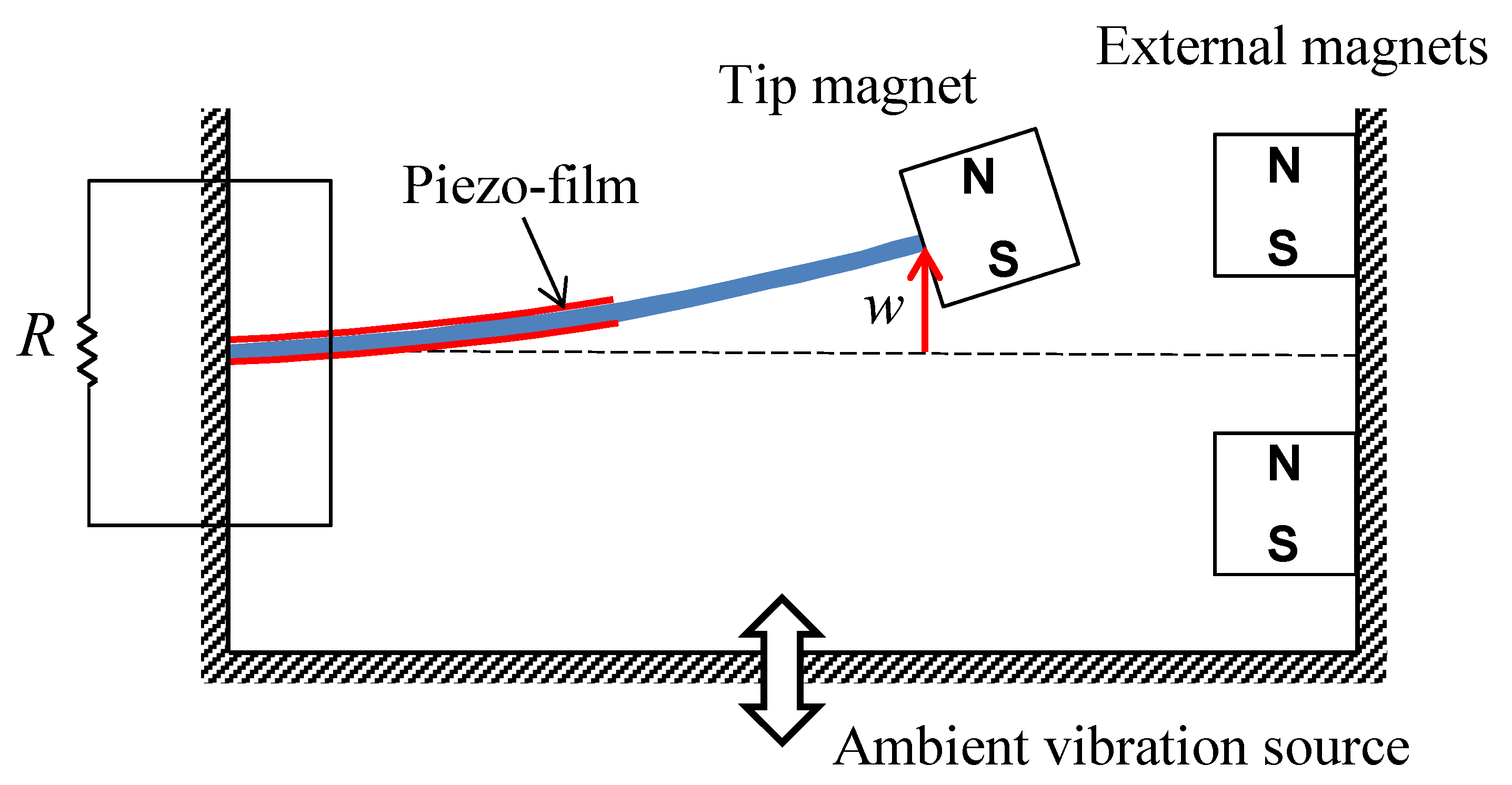
Figure 1 shows the schematic diagram of the magnetic repulsion bistable energy harvester considered in this study. The energy harvesting system is composed of a piezoelectric bimorph cantilever beam, to the free end of which a permanent magnet is attached (called the tip magnet in this study), and two other external permanent magnets. As shown in
Figure 1, the bimorph beam and external magnets are fastened to a magnetically inert support frame that moves with the base. For the bimorph cantilever beam, the stainless-steel shim is partially covered, on its upper and lower surfaces, with two identical piezoelectric polymer films that are polarized oppositely in the direction of thickness. The major surfaces of each piezoelectric layer are fully coated by conductive electrodes. These two piezoelectric layers, and an external load resistance, are electrically connected in series. The geometric parameters and material properties of the bistable energy harvester are given in
Table 1. When the base is excited by a certain ambient vibration, the mechanical deflection or strain of the piezoelectric beam, owing to its forced vibration, is transduced into electrical current flowing through the external load resistance. Using this structure for piezoelectric transduction, the energy harvesting system can harvest some useful electrical energy from ambient vibration sources for powering autonomous micro-devices.
For the mathematical modeling of the bistable energy harvester under consideration (
Figure 1), the piezoelectric bimorph cantilever beam is described by the Euler–Bernoulli beam theory and linear piezoelectricity. The magnetic repulsion forces and moment between the tip magnet and external magnets are described by the magnetic dipole model, which can be considered in the boundary conditions at the tip of the beam. After a series of derivations within the above modeling framework [
20,
22], the electromechanical oscillator model for the bistable energy harvester can be obtained in the form:
where
is the tip displacement of the bimorph beam;
and
are the natural angular frequency and damping ratio, respectively, of the linear system;
,
, and
are the coefficients of the equivalent magnetic repulsive force determined by the relative position of the three permanent magnets;
and
are the electromechanical coupling constants;
is the voltage across the external load resistance
;
is the equivalent capacitance; and
and
are the amplitude and frequency of the base acceleration, respectively. Additionally, for the purpose of generality, Equations (1) and (2) are nondimensionalized in the form [
25]:
by introducing the following dimensionless variables and parameters to Equations (1) and (2):
where
is the nontrivial static equilibrium of the system and
is the optimal resistance of the linear system.
3. Broadband Characteristics of a Bistable Energy Harvester: Primary Harmonic and Subharmonic Interwell Motions
To investigate the nonlinear dynamic behaviors of the bistable energy harvester, a series of frequency response analyses are carried out in this section. Firstly, the dimensionless governing differential equations for the bistable energy harvester are rewritten, by substituting the state vector
into Equations (3) and (4), as the following state equations:
The steady-state forced response of the bistable energy harvester is calculated by the direct numerical integration of Equation (6), based on the Runge–Kutta method, and its stability is determined by Floquet theory [
32]. The Floquet multiplier of the steady-state response is evaluated by solving the eigenvalue problem of the monodromy matrix:
where
is the Jacobian matrix of a system of state equations (given by Equation (6)) and
is the number of discrete times in a given period. The steady-state response solution is obtained while the frequency of the base excitation varies by means of frequency sweeping or frequency marching. The baseline parameter values given in
Table 1 are used for all the numerical simulations, and the associated dimensionless parameters are given as
,
,
,
,
, and
, unless otherwise stated.
Figure 2 shows (a) frequency displacement responses and (b) the associated output power responses for the intrawell and interwell motions of the piezoelectric bistable energy harvester, which are evaluated when the amplitude of the base acceleration is given as
A = 0.016. As shown in this figure, the steady-state periodic responses are classified into three types of oscillations: the small-amplitude intrawell motion (1
T-SO), the primary harmonic interwell motion of period 1
T (1
T), and the subharmonic interwell motion of period 3
T (3
T), where
T is the forcing period of the base excitation defined by
T = 2
π/
ω. The existence of these multiple solutions is one of the most important features of nonlinear systems. In particular, for a bistable system, either intrawell or interwell motion appears depending on the initial conditions of the system, which is caused by the saddle barrier of the double-welled potential energy function shown in
Figure 3a.
In the potential energy function, there is one unstable trivial static equilibrium (designated by the saddle point), and there are two stable nontrivial static equilibria (designated by the center points). When the intensity of the base excitation is relatively weak (smaller than a certain threshold value), the kinetic energy of the bistable system is not enough to cross over the saddle point and, accordingly, the oscillation of the system tends to be limited within one of the two symmetric potential wells (i.e., intrawell motion). This intrawell motion oscillates with a small amplitude, around the stable nontrivial equilibrium in the potential well, producing relatively low electrical power. When the base excitation becomes relatively strong (larger than a certain threshold value), the bistable system attains enough kinetic energy to move across the potential saddle barrier. In this case, a large-amplitude interwell motion abruptly appears and produces higher electrical power than an intrawell motion.
Figure 3b shows the state-space representation of the small-amplitude intrawell motion and the primary harmonic (period-1
T) and subharmonic (period-3
T) interwell motions, which are obtained when
A = 0.016 and
ω = 0.5. In this figure, the difference between the intrawell and interwell orbits is clearly observed. The amplitudes of the orbit oscillations are of the following order, largest to smallest: the primary harmonic interwell motion, the subharmonic interwell motion, and the intrawell motion. The harvested electrical powers also tend to be the highest in the same order (as can be seen from
Figure 2b). Therefore, the interwell motions are more advantageous than the intrawell motion in energy harvesting applications.
In terms of energy harvesting applications, it is also very important that the interwell motion of the bistable energy harvester occurs in a broad frequency band, which is notably different from the linear system. For this reason, many research efforts have been devoted to the development of a broadband bistable energy harvester for real-world applications, in which the ambient vibration energy sources have time-varying and/or multiple frequency components. However, the majority of them mainly focus on the primary harmonic interwell motion. Recent reports [
30,
31] show that subharmonic interwell motions as well as primary harmonic interwell motions are suitable for broadband energy harvesting applications. As shown in
Figure 2, if the bistable system is properly designed, the frequency bands of the primary harmonic and subharmonic interwell motions tend to form a whole wide frequency band.
4. Optimization of the External Load Resistance of the Bistable Energy Harvester
As mentioned before, the external load resistance of the piezoelectric bistable energy harvester is one of the important design factors that should be optimized in order to maximize the harvested electrical power. In this section, the optimal value of the external load resistance is estimated numerically and analytically for primary harmonic and subharmonic interwell motions.
Figure 4 shows (in the first column) the time responses of the primary harmonic and subharmonic interwell motions evaluated when
A = 0.016 and
ω = 0.5, and (in the second column) the associated amplitude spectra obtained by the Fourier analysis. As shown in
Figure 4a, the oscillation periods of the primary harmonic and subharmonic interwell motions are 1
T and 3
T, respectively, where
T (=2
π/
ω) is the forcing period of the base excitation; thus, the fundamental oscillation frequencies are
ω and (1/3)
ω, respectively. It is interesting that the fundamental frequency of the subharmonic motion is three times smaller than the forcing frequency, which is considered in the optimization process of the external load resistance. Based on the results of the Fourier analysis (
Figure 4b,d), the solutions of the primary harmonic and subharmonic interwell motions can be assumed in the forms of the truncated Fourier series:
where the symbol
k is used to indicate the primary harmonic motion (
k = 1) or subharmonic motion (
k = 3);
,
,
, and
are the Fourier coefficients; and all the constant terms are set to zero for the interwell motions, the center of oscillation of which is the trivial static equilibrium point (
x = 0).
Substituting the assumed solutions of displacement and voltage (Equation (8)) into the differential equation of the equivalent circuitry (Equation (4)), and manipulating the resulting equation, the voltage amplitude
of the
nth-order harmonic term in the solution and the resulting average power
can be obtained as functions of the displacement amplitude
in the forms:
where
and
. Subsequently, to estimate the optimal value of the external load resistance for maximizing the output power, the optimization problem of
is formulated. For further simplification, if the third harmonic terms are removed from the solution (Equation (8)), since they are much smaller than the first harmonic terms, the optimization problem takes the form:
where it is assumed that the displacement is almost invariant with respect to change in the external load resistance. The above optimization problem can be analytically solved, and the resulting optimal resistance is written by
. The optimal resistance of the linear system can be obtained as a limiting case when the external magnet is removed away from the energy harvesting system, i.e.,
. Additionally, the optimal load resistance is also estimated numerically for comparison purposes. The steady-state voltage response is evaluated by the direct numerical integration of Equation (6), and then it is used to obtain the numerical optimal resistance that maximizes the resulting average power response.
Figure 5 shows the average output electrical power of the bistable energy harvester, with respect to the external load resistance, which is harvested from (a) primary harmonic and (b) subharmonic interwell motions. In this figure, the three different optimal resistances are presented together and compared: the optimal resistance
(denoted by the square point) is evaluated numerically, with which the output power becomes maximized; the optimal resistance
(the circle point) is estimated analytically by Equation (10); and the optimal resistance
(the triangle point) of the linear system. As shown in
Figure 5, the analytical results for the optimal resistance are well matched with the numerical ones (with a maximum relative error of 3.8%) for both primary harmonic and subharmonic interwell motions. However, the optimal values
and
are very different from the optimal value
. Such a difference tends to be larger as the forcing frequency of the base excitation decreases, and it becomes more remarkable for the subharmonic motion (
Figure 5b), when compared with the primary harmonic motion (
Figure 5a). These observations indicate that the optimal resistance tuned for the linear energy harvester is not appropriate for the bistable energy harvester, and the optimal load resistance is affected by the forcing frequency of the base excitation.
Figure 6 shows the optimal load resistance for the primary harmonic and subharmonic interwell motions of the piezoelectric bistable energy harvester, which are obtained with three different amplitudes of the base excitation:
A = (
a) 0.011, (
b) 0.016, and (
c) 0.020. In this figure, the optimal load resistances are evaluated over the frequency band, where the primary harmonic and subharmonic interwell motions occur. The three different types of the optimal resistances
,
, and
are designated by the dotted, solid, and dashed–dotted lines, respectively. As shown in
Figure 6, the analytical optimal load resistances are in excellent agreement with the numerical ones, which strongly supports the validity of the analytical estimation of the optimal load resistance made in this study. The frequency dependency of the optimal resistance is more clearly observed; the lower the forcing frequency of the excitation is, the larger the optimal resistance is, for both the primary harmonic and subharmonic interwell motions. Additionally, it is worth noting that the optimal load resistances for the subharmonic motions are approximately three times larger than those for the primary harmonic motions. This means that the optimal resistance actually depends on the oscillation frequency of the interwell motion, rather than the forcing frequency of the base excitation.
Figure 7 is the comparison of the optimal load resistance evaluated numerically with three different base accelerations. As shown in this figure, the optimal load resistance
almost does not vary with the amplitude of the base acceleration, although the frequency bands of the interwell motions tend to be broader. In other words, the optimal resistance is not sensitive to changes in the intensity of the base excitation.
In this study, the optimal value of the load resistance of the bistable piezoelectric energy harvester subject to harmonic base excitation was estimated and investigated for primary harmonic and subharmonic behaviors, and it was shown to be affected by the oscillation frequency of the system rather than the forcing frequency. Actually, there are various types of ambient vibration sources, e.g., harmonic, periodic, impulsive, and random excitations. Depending on the type of ambient vibration source, the passive load resistance of the bistable piezoelectric energy harvester should be optimized in an appropriate manner to maximize the average output power over the whole time interval. Alternatively, an adaptive resistance can be employed for piecewise harmonic excitations, or for slowly-varying excitations such as swept-sine excitation of a small sweep rate, although this is used less commonly than a passive resistance. For an adaptive resistance, additional electronic parts, e.g., an appropriate power conditioning circuit and a feedback controller, are required to adjust source or load impedance. In this case, the results for the optimal load resistance presented in this study would be useful in adaptation algorithms.
For all the simulations performed in this study, the same material properties and geometric parameters listed in
Table 1 were used, except for the external load resistance. Note that changes in the mechanical and electromechanical properties of the bimorph composite beam possibly affect the operating frequency band and output power of the energy harvester, but they do not alter the fundamental dynamic features of the bistable system such as the bifurcation structures of primary harmonic and subharmonic interwell motions. Thus, the results and discussion presented in this study would also be valid for different geometries and/or materials of the beam.


