Article

Bottom Sediments from a Dam Reservoir as a Core in Embankments—Filtration and Stability: A Case Study

1
Department of Rural Building, University of Agriculture in Kraków, al. Mickiewicza 24/28, 30-059 Kraków, Poland
2
Department of Hydraulic Engineering and Geotechnics, University of Agriculture in Kraków, al. Mickiewicza 24/28, 30-059 Kraków, Poland
*
Author to whom correspondence should be addressed.
Sustainability 2021, 13(3), 1221; https://doi.org/10.3390/su13031221
Submission received: 19 November 2020 / Revised: 8 January 2021 / Accepted: 13 January 2021 / Published: 25 January 2021

Abstract

:
A possibility of using bottom sediments from dam reservoirs in earth structures was considered. Sediments from the Rzeszow reservoir (Poland) were used as research material, which, according to geotechnical standards, were classified as low permeable silt with high organic content. As fine, cohesive soil with a low coefficient of permeability, the sediments can be used in sealing elements of hydraulic engineering embankments. In order to verify the suitability of the sediments, stability and filtration calculations were carried out for embankments with a sealing in the form of a core made of the sediments. It was stated that by using a core made of sediments, the volume of seepage on the downstream side during continuous or variable backwater was significantly lower in relation to an embankment without a core, and the phreatic line did not extend to the downstream slope. It is estimated that, in the case of a planned dredging in Rzeszow Reservoir, the amount of dredged sediment would exceed 1.5 million m3, and therefore, the possibility of their economic use is essential. The search for materials that could replace natural soil in earthen structures is an important issue from both the ecological and economic points of view.

1. Introduction

Hydraulic engineering embankments are earth structures temporarily or permanently damming water. They fulfill a variety of functions as levees, embankments of rivers, causeways, and so forth. These structures have a trapezoidal shape, and depending on the class or function, they may include sealing and drainage elements within the body and the subsoil (Figure 1).
Granular materials with the greatest particle size distribution should be used to form embankments. In the construction of the embankments of rivers and water reservoirs, their proper tightness should be ensured to prevent excessive water filtration through the body of the earth structure and water leaks, which would pose a threat to the stability of the structure and surrounding area [1,2,3]. The soil used for forming the embankments should therefore be resistant to water. In the case of using permeable materials, the use of additional sealing in the form of a screen or a core should be considered. Depending on the place of incorporation into the embankment, the soil should be characterized by different requirements. For the construction of the outer part of an earth-fill dam, the so-called static part, stony soil (screen, residual clay soil, and cobbles), coarse-grain soil (gravel and gravel–sand), and fine non-cohesive soil (sand) can be used. Cohesive soils (clay, silt, gravel sand mixed with clay, and gravel mixed with clay) are incorporated into the dam seal and are designed to reduce the filtration through the dam body.
Due to difficulties in obtaining suitable natural soils for incorporation, whose resources are limited and non-renewable, research continues on materials that could replace them [5,6]; industrial waste is a typical example [7,8]. In this situation, the use of bottom sediment from dam reservoirs is also worth considering [9]. One of the main problems related to the performance of reservoirs is protection from sediment deposition [10]. Since the process of silting occurs in every dam reservoir, the extraction of sediments is one of the ways to recover lost volume and to restore proper functioning of the reservoir. In Poland, water reservoirs in the south, especially in the Carpathians, get silted up the fastest [11].
The silting of water reservoirs as a result of the sedimentation of material carried by tributaries causes a decrease in their capacity. The intensity of the silting process depends on the surface and topography of the catchment area, its use, types of soil, as well as the precipitation intensity and duration. The type and location of the reservoir, as well as the hydrological regime of the river, also play an important role. Therefore, considering reservoir water management, it is important to determine the rate of the siltation process, and thus, the amount of mineral and organic material deposited in the reservoir. It is believed that if the capacity is reduced by 80%, the reservoir loses its retention function [12].
According to the Act [13], bottom sediments are classified as waste and should be disposed of when they are extracted. However, if they are moved within surface waters for purposes related to water management or reducing the effects of floods, drought, or remediation, these sediments are not dangerous [14]. While considering the potential use of bottom sediments, another important aspect is their pollution. The chemical composition of the sediments depends on the type of soils in the catchment area and their agricultural use, as well as the type of industry present in the area [15,16,17]. Therefore, identification of the chemical composition of bottom sediments using chemical and ecotoxicological analyses is important, not only to assess the degradation of the water reservoir, but also to determine the potential applications of the extracted sediments [18,19]. There is also research carried out on anaerobic methane oxidation processes, which occur in sediments that create habitats in freshwater dam reservoirs of small volumes; these processes play a significant part in global warming [20].
Bottom sediments that show a neutral or alkaline reaction and high content of fine fractions can be used to improve physicochemical properties of light and acidic soils [21]. The possibilities of the agricultural use of sediments are mainly connected with a low content of heavy metals, but also an appropriate content of available forms of magnesium, potassium, and phosphorus, which prove their fertility. Research on the potential uses of bottom sediments, including agricultural, was carried out by Fonseca et al. [22], Canet et al. [23], Baran et al. [24], and others. Using the example of sediments from the Rożnów reservoir located in southern Poland, Tarnawski et al. [25] indicated that there is a great possibility of using sediments for environmental purposes (agriculture, reclamation). In order to fully assess their potential usage, it is necessary to analyze the ecological risk connected to their extraction and possible environmental pollution with heavy metals, PAHs (polycyclic aromatic hydrocarbon), PCBs (polychlorinated biphenyl) [25]. These materials can also be used in the reclamation of mine and energy waste landfills, especially the ones with fly ashes [26]. Sediments in dam reservoirs, if they meet geotechnical requirements, can be a full-value material that can be used in earth constructions [9,27,28]. These materials should not contain more than 3% of organic parts and not more than 5% of water-soluble parts [2]. In plastic sealing elements of hydrotechnical embankments, mainly cohesive soils should be used, which contain more than 25% of particles with a diameter smaller than 0.01 mm, and the permeability coefficient of such soils should be less than 10−7 m⋅s−1. There is also research on bottom sediments stabilized by the addition of bentonite [28,29] and using bottom sediments in brick production [30].
There has also been research conducted on the characteristics of sediments deposited in the bottom of lakes and seas, but from the point of view of their geological structures [31,32,33]. For example, tests on the sediments from Lake Bergsee in southern Germany have shown that they are much weaker and highly-compressive compared to the sediments from Scandinavian lakes [31]. Whereas Ballas et al. [33] showed that sediments in the Romanian part of the Black Sea are highly plastic, clayey materials that have high compressibility, low shear strength, and moderate sensitivity. They also noticed a slight increase in the shear strength of sediments where the precipitation of iron sulphides and calcium carbonates occurred, which cemented this material. Ballas et al. [33] clearly indicate that it is the cementation process, connected with the precipitation of chemical compounds, that causes the seabed to be stable.
The purpose of the work was to analyze the filtration output and stability of an earth embankment with a seal made of fine-grained bottom sediments in the form of a central core and a cut-off wall in the ground. The calculations were also made for the embankment without these seals. The results of the tests on the geotechnical parameters of the bottom sediments from a water reservoir in Rzeszów (Poland) were used in the calculations. The calculations were carried out to assess the usability of bottom sediments from that reservoir for earthworks, in particular, in hydrotechnical constructions. The purpose of the work resulted in the need to look for materials, other than natural mineral soils, that could potentially be used as a sealing material in hydrotechnical earth embankments. As shown above, there are a number of studies describing problems related to the chemical pollution of bottom sediments from dam reservoirs and possible attempts to use them in agriculture. However, there are very few studies related to the use of sediments in earthworks; moreover, the amount of deposited material is significant, so their economic potential is great.

2. Materials and Methods

2.1. Study Area

The water reservoir in Rzeszów (Podkarpackie Voivodeship, Rzeszów, Poland) was created in 1973 as a result of building a barrage in 63.7 km of the Wisłok River (Figure 2). Initially, the reservoir capacity was 1.8 million m3, and its area was 68.2 hectares. The catchment area of the reservoir is 2060.7 km2, with a total catchment area of the Wisłok River of 3528.2 km2. As a result of the silting process, the reservoir is currently about 60% silted up, so its original functions cannot be fully realized. It is estimated that approximately 1.5 million m3 of bottom sediments may be extracted from the reservoir. This intensive silting process is mainly the result of the way the catchment area is used, where agricultural land is over 70% (arable land—53.9%, orchards—1.8%, meadows and pastures—14.3%) [34]. The remaining part of the catchment area is forest land. In the catchment area, for the most part, there are poorly permeable, brown and silty soils, as well as alluvial soils with a mechanical composition of heavy clays and clayey silts [34].

2.2. Geotechnical Parameters

Bottom sediment tests were carried out on an averaged material, which was a mixture of all samples taken from the bottom of the reservoir. The scope of the research included grain size composition, specific density, consistency limits, compaction parameters, shear strength, coefficient of permeability, and organic matter content. The grain size composition was determined by the areometric method [35,36], and the specific density by the pycnometer method [37]. Consistency limits, that is, the liquid limit, was determined by the Casagrande method, and the plastic limit, by the standard thread rolling method [38]. Compaction parameters, that is, the optimum moisture content and the maximum dry density, were determined in the Proctor apparatus at the compaction energy of 0.59 J⋅cm−3 [39]. Shear strength parameters, the angle of internal friction and cohesion, were determined in a direct shear apparatus [40]. Samples measuring 60 × 60 mm were formed directly in the apparatus box at the optimum moisture content to achieve the compaction index IS = 1. The samples were subjected to normal stress of 50, 100, and 200 kPa, and then sheared at a rate of 0.1 mm⋅min−1. The coefficient of permeability was determined in an oedometer, on samples (diameter—6 cm, height—2 cm) formed at optimum moisture content and a compaction index of IS = 1. The organic matter content was determined by two methods: oxidation and loss on ignition [41].

2.3. Stability and Filtration Calculations

Two methods were used to calculate slope stability: the analytical Bishop’s limit equilibrium method and the numerical finite element method. The Bishop’s method is a limit equilibrium method, where the potential landslide mass is divided into blocks with vertical walls, for which the resisting and sliding forces are analyzed. The factor of safety refers to the strength parameters of the soil, so it is determined how much the values of the angle of internal friction and cohesion should decrease for the slope to lose stability. It is assumed that, along the potential slip surface, the soil is plastic and meets the Mohr–Coulomb limit condition. The calculations were made using the GeoStudio package—the SLOPE/W software was used for stability, and SEEP/W for filtration [42].
Z_Soil.PC software was used to calculate the stability and filtration, by the finite element method [43]. As a model of soil, the elastic-perfectly plastic Mohr-Coulomb model was used and the method of reducing the shear strength parameters was used to determine the factor of safety. The method of reducing shear strength is based on reducing the values of the angle of internal friction (φ) and cohesion (c) in subsequent calculation steps, maintaining the ratio F S = tan φ tan φ F = c c F that determines the factor of safety (FS). The values φF and cF are the limit values of the angle of internal friction and cohesion; when they are exceeded, the shearing process starts. The method allows for the determination of the slip surface where the balance between shear stress and shear strength was obtained the fastest. Reducing or increasing the parameters allows for the determination of consecutive failure surfaces and tracking of the destruction process [44]. The stability analysis was carried out for the case of flat deformation (two-dimensional analysis).
Filtration calculations were carried out in the conditions of steady and non-steady filtration. In the case of steady-state filtration, the filtration pressure distribution depends only on the coefficient of permeability of individual materials, and the values of the coefficients themselves determine, in turn, the flow rate—the parameters describing the flow in the unsaturated zone are of secondary importance [45]. In the case of unsteady filtration in the unsaturated zone, a model that takes into account the changes in conductivity related to the presence of the air should be used. The specificity of water flow through the unsaturated zone is related to the time and space variable pressure distribution, which depends directly on the degree to which the pores are filled with water, that is, the volume moisture content. In the unsaturated zone, the pore pressure is lower than atmospheric pressure and has a negative value. The van Genuchten model was used to describe unsteady filtration, which illustrates the relationship between conductivity and the degree of saturation, as well as the relationship between the degree of saturation and the value of negative water pressure [46]. According to van Genuchten [47], the relative permeability coefficient is described by the following equation:
k w ( h ) = k s · { 1 ( α · h ( n 1 ) ) · [ 1 + ( α · h n ) m ] } 2 [ ( 1 + α · h ) n ] m 2
The value of the permeability coefficient is a function of suction pressure, which, in turn, depends on the volumetric moisture content of the soil:
θ = θ r + ( θ s θ r ) [ 1 + ( α · h ) n ] m ,
where ks (m·s−1) is the saturated permeability coefficient, kw (m·s−1) is the unsaturated coefficient of permeability, θ (−) is the volumetric moisture content, θs (−) is the saturated volumetric moisture content, θr (−) is the residual volumetric moisture content, h (cm) is the pressure head in cm, the water column, is α (cm−1), and the n and m constants are ( m = 1 1 n ).
It was assumed that the bottom sediments and soil in the body of the dam and in the subsoil had the same vertical and horizontal hydraulic parameters. The coefficient of permeability was determined based on the authors’ tests, and the parameters of the van Genuchten equation were estimated in the RETC program, based on the geotechnical characteristics of the soils (grain size composition, bulk density) [48,49,50]. The values of the Young modulus (E) and Poisson ratio (ν) do not have an influence on the factor of safety [44], so for each material, the default values were assumed to be E = 100 MPa, ν = 0.3, and the angle of dilatancy, ψ = 0°.
The calculations were made for the assumed embankment structures made of medium sand without seals and with a seal in the form of a core made of bottom sediments from the Rzeszów reservoir. The seal was in the form of a centrally located core width of 1 m in the upper part, enlarged at the base of the embankment, prolonged in the ground in the form of a vertical wall, maintaining the unsealed zone below the wall with a thickness equal to the height of the dam, according to the relevant requirements [51]. The foundation of the embankments was assumed to be on the ground built with permeable medium sands laying on an impermeable layer of clay. Calculations using the Bishop’s method were made for two calculation cases: without backwater and with continuous backwater; and using the FEM method, for three calculation cases: without backwater, with continuous backwater, and with variable backwater (dependent on the flood wave). It was assumed that during the passage of a flood wave, the water level rises to the maximum backwater level for two days (t = 2 d), remains at a constant level for three days (t = 5 d), after which the water level falls for two days (t = 7 d). The crest width of the embankments was assumed to be 3 m, with a slopes gradient of 1:2, heights of 4, 6, and 8 m, and position of the water level 1.5 m below the crest (Figure 3). According to the regulations on technical conditions to be met by hydrotechnical structures and their location, which are enforced in Poland [52], the minimum safety factor—regardless of the building class or with detailed tests on the parameters of soil in the body and ground under the basic load system—is FS = 1.3.

3. Results

3.1. Characteristic of Bottom Sediments

Bottom sediments taken from several places of the Rzeszów reservoir were classified as well-grained coarse silts or coarse clayey silts (Figure 4). The grain size composition was dominated by the silt fraction, which was from about 86% to 92%; the sand fraction was from 1% to 2%, and the clay fraction, from 6% to almost 13%. The specific density was from 2.58 to 2.62 g⋅cm−3.
The high content of silt is related to the location of the reservoir (in the downstream part of the Wisłok river), the predominance of silty soils in the catchment area, and the presence of the Besko reservoir in the upstream part of that river, where coarser fractions are accumulated [53]. In addition, this reservoir was built in the part where Wisłok is a lowland river, so the water flow velocities are low.
The other geotechnical parameters of the sediments were determined for the averaged sample. It was assumed that, during extraction, the sediments would be mixed and, as such, built into earthen embankments.
The material was characterized by an increased content of organic parts; the loss on ignition amounted to nearly 5%, while organic content was over 3%, which should qualify it as a low-organic soil. Sediments are a low permeable material, and the filtration rate decreased from 1 × 10⁻⁸ to about 1 × 10⁻⁹ m·s−1, with an increase in the compaction index from 0.9 to 1. The liquid limit of the Rzeszów reservoir sediment was above 40%, while the plasticity limit was about 27%, so the material was characterized by a high plasticity index of close to 14%. The maximum dry density was 1.4 g·cm−3 at the optimum moisture content of 27%. Sediments at the optimum moisture content were characterized by relatively high values of the angle of internal friction and cohesion. The angle of internal friction increased from 23° to almost 34° and cohesion from 33 to about 36 kPa, respectively [53].
The values of the geotechnical parameters for stability and the filtration calculations were adopted based on the test results (Table 1). The geotechnical parameters of the medium sand, which was in the body of the hydrotechnical embankment, and the clay (impermeable layer) were adopted based on the authors’ own tests.
As fine, cohesive soil with a low coefficient of permeability, the Rzeszow reservoir bottom sediments meet most of the Polish criteria [2,54] for sealing elements in hydraulic engineering embankments (Table 2). They were characterized by an appropriate coefficient of permeability and fine particle content. In the case of two parameters—the coefficient of uniformity and organic content—a value slightly lower than required was obtained (the coefficient of uniformity was 13.3, with the desired value of at least 15, and the organic content was 3.3%, with a limit value of 2% or 3%, depending on the source). Therefore, bottom sediment could be used as a construction material in the sealing elements in hydraulic engineering embankments [53].
Gwóźdź [9] has also researched the possibility of using bottom sediments for earth constructions. His research has shown that the sediments from the Rożnów reservoir (Poland) are suitable for mineral sealing layers in landfills. Their coefficient of permeability ranged from 1.1 × 10⁻⁹ to 4.7 × 10⁻¹⁰ m·s−1, with an increase in compaction from IS = 0.95 to 1 [9], and the plasticity index was PI = 15 ÷ 65, which also indicates the usefulness of this material. The value of compaction index (IS) expresses the ratio of the dry density of soil for moulded samples in laboratory tests to the value of the maximum dry density determined in a Proctor’s method. The value of compaction index (IS) expresses the ratio of the dry density of soil for molded samples in laboratory tests (or from the field test) to the value of the maximum dry density determined in a Proctor’s method. Whereas the plasticity index (PI) is a measure of the plasticity of a soil and is the size of the range of the moisture contents at which the soil remains plastic.

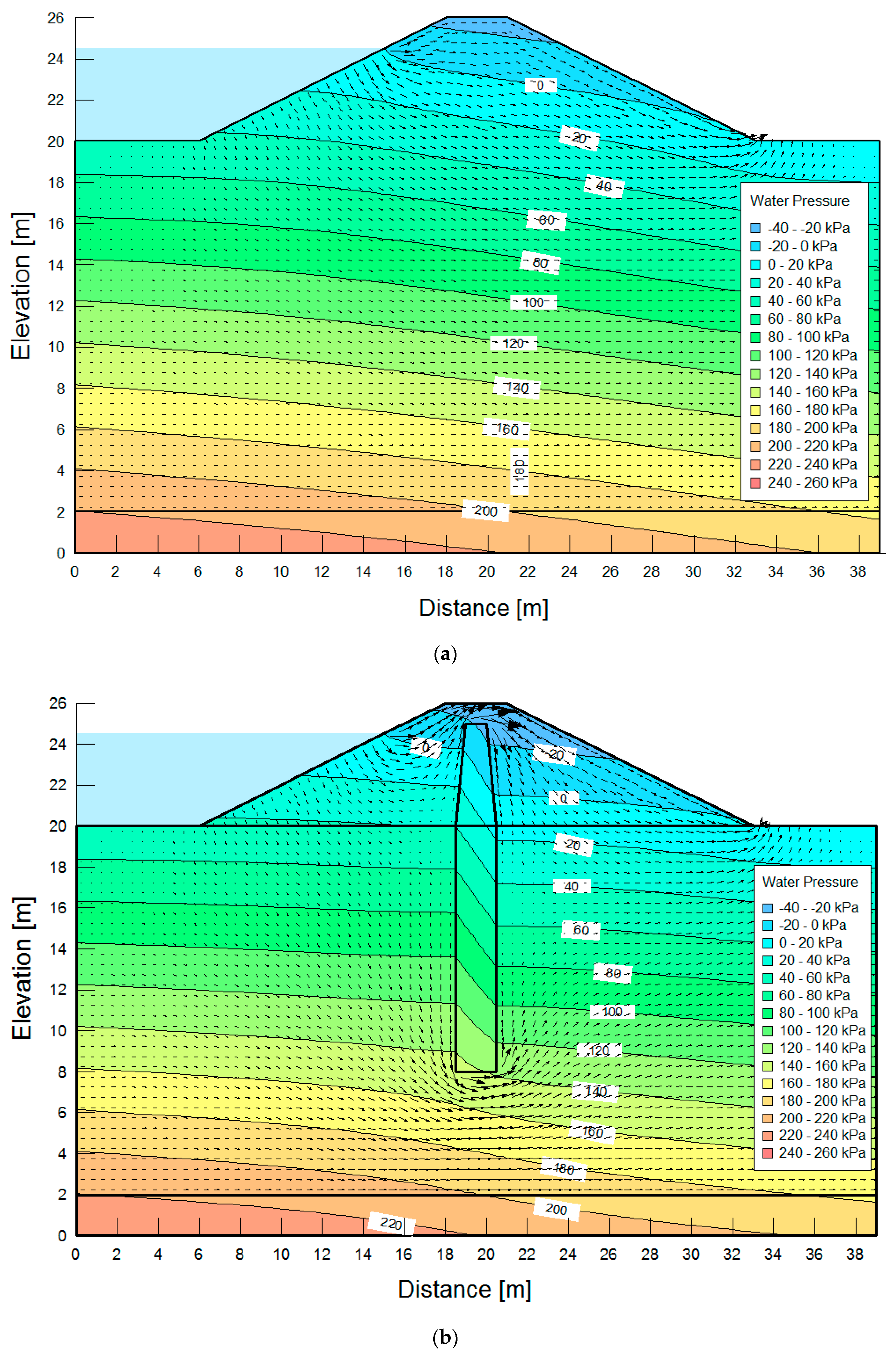
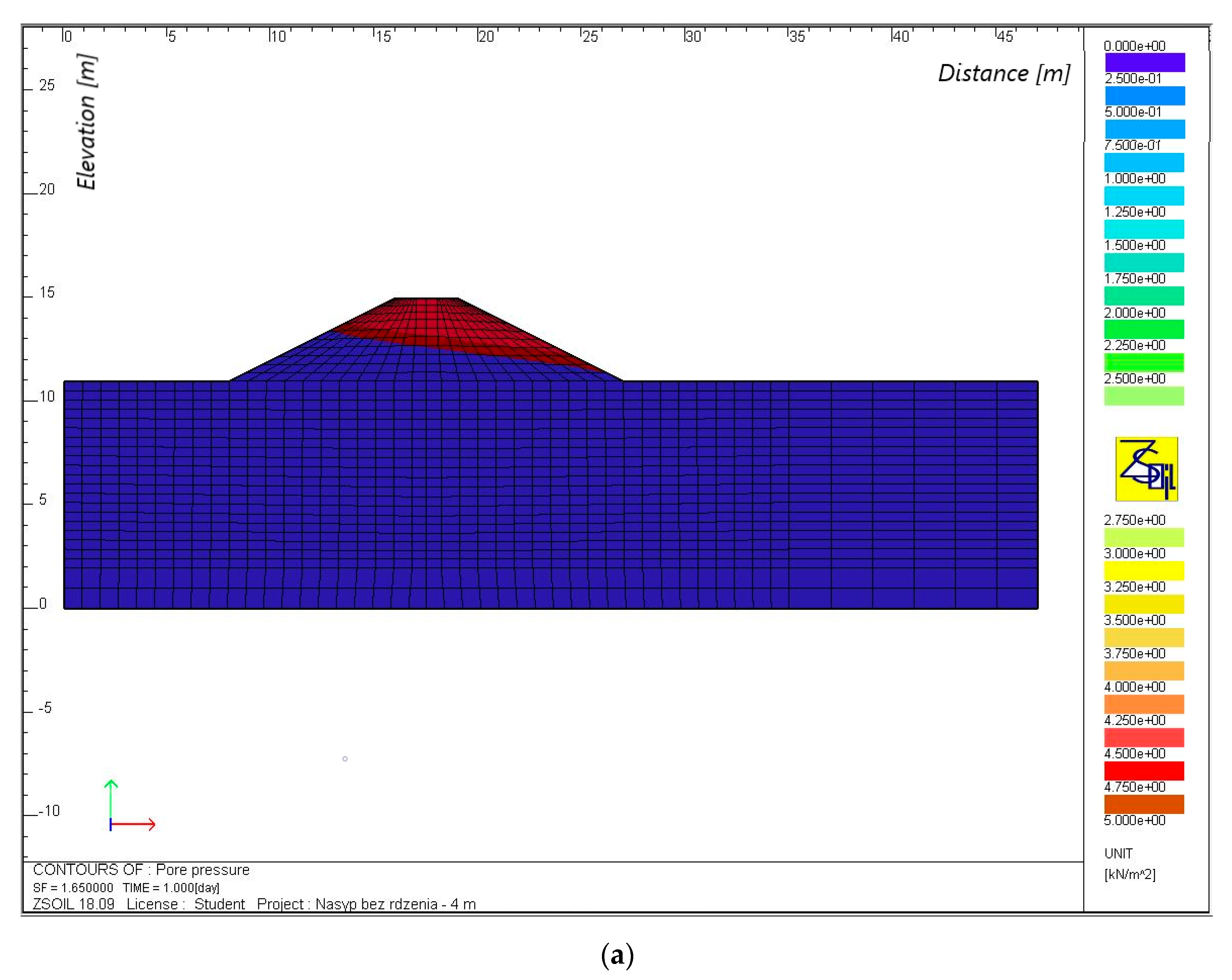
3.2. Filtration Calculations

In each calculation case in the GeoSlope software for an embankment without a core, seepage occurred on the downstream slope. The phreatic line decreased as a result of using seals in the form of a core made of bottom sediments from the Rzeszow reservoir. Figure 5 shows exemplary pore water pressure values in the body of the embankment and its base with and without the seal. The course of phreatic lines and a significant reduction in water pressure indicate a restriction of the water flow.
Calculations of the seepage through the body and base of the embankment using the finite element method showed that the value of the seepage for an embankment without a core was large and ranged from 7.4 to 32.1 m3·(d·m)−1, depending on the height of the embankment (Table 3). Considerably lower values were obtained for an embankment with a core—from 4.4 to more than 13.2 m3·(d·m)−1; there was thus an approximately two-fold reduction in the size of seepage.
The analysis of seepages for the embankment with and without sealing, and with continuous and variable backwater, shows significant differences in the obtained values (Table 3). Seepages through the downstream slope and the subsoil for an embankment without a core were high and ranged from over 7 to 32 m3·(d·m)−1, depending on the height of the embankment. The use of seals in the form of a core made of bottom sediments resulted in a lower phreatic line, a significant reduction in seepages, which amounted to more than 4 to 13 m3·(d·m)−1.
Detailed analysis of seepage through the embankment showed that the differences in its values between the continuous and variable backwater were small (Table 3). These values did not exceed 0.5 and 0.3 m3·(d·m)−1 adequately with and without the sealing. The same was found for the base of the embankment, but here the differences did not exceed 0.15 m3·(d·m)−1. On the other hand, there was a significant reduction of the seepage through the body of the embankment and its base with or without a sealing. The seepage through the body decreased by two to six times with an increase of the embankment height from 4 to 8 m. On the other hand, the seepage through the subsoil decreased two times as a result of using sealing, regardless of the height of the embankment. In conclusion, it should be clearly stated that the use of bottom sediments from the Rzeszów reservoir to seal the body of the embankment and its base significantly reduced the size of seepage.

3.3. Stability Calculations

3.3.1. Bishop’s Method
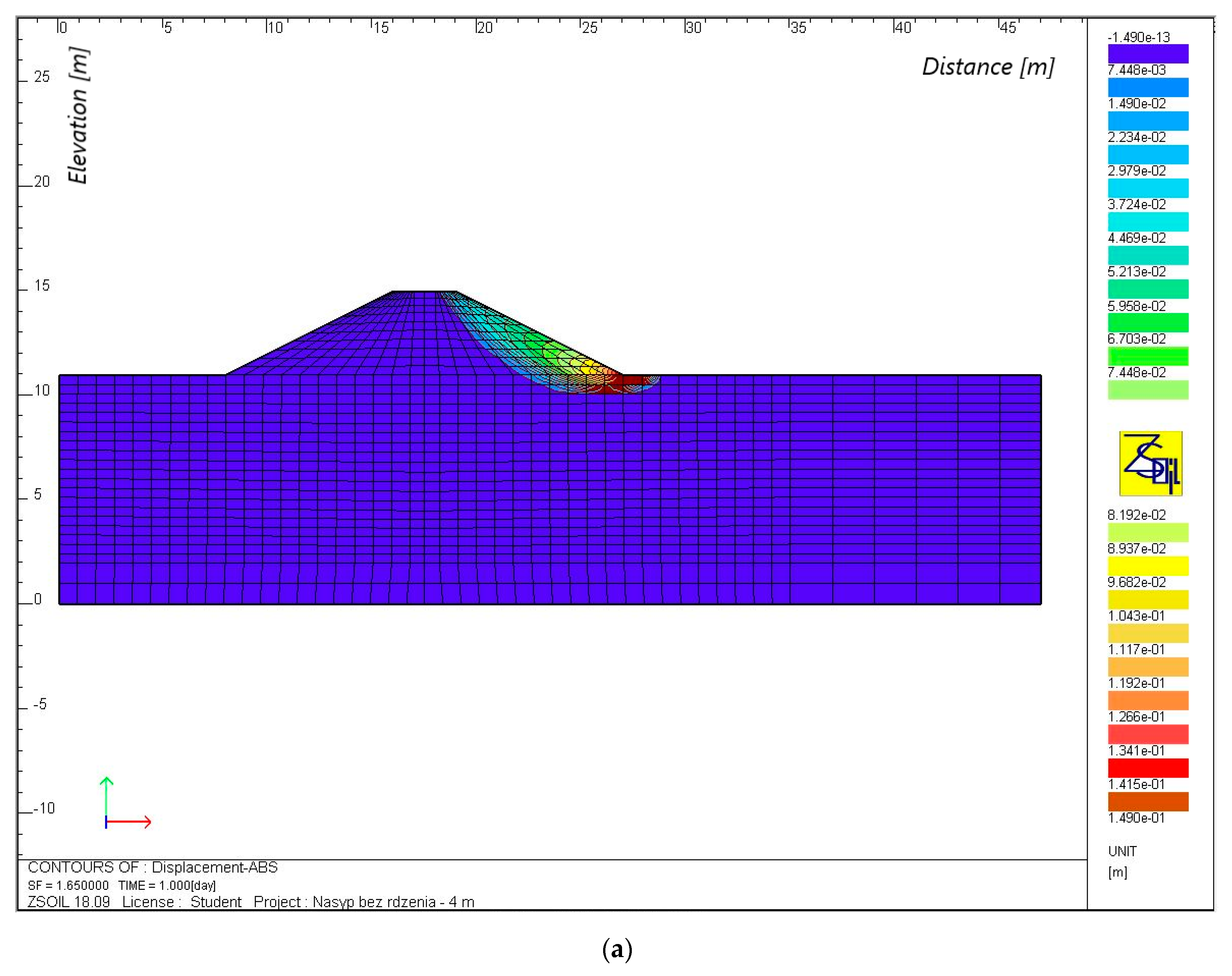
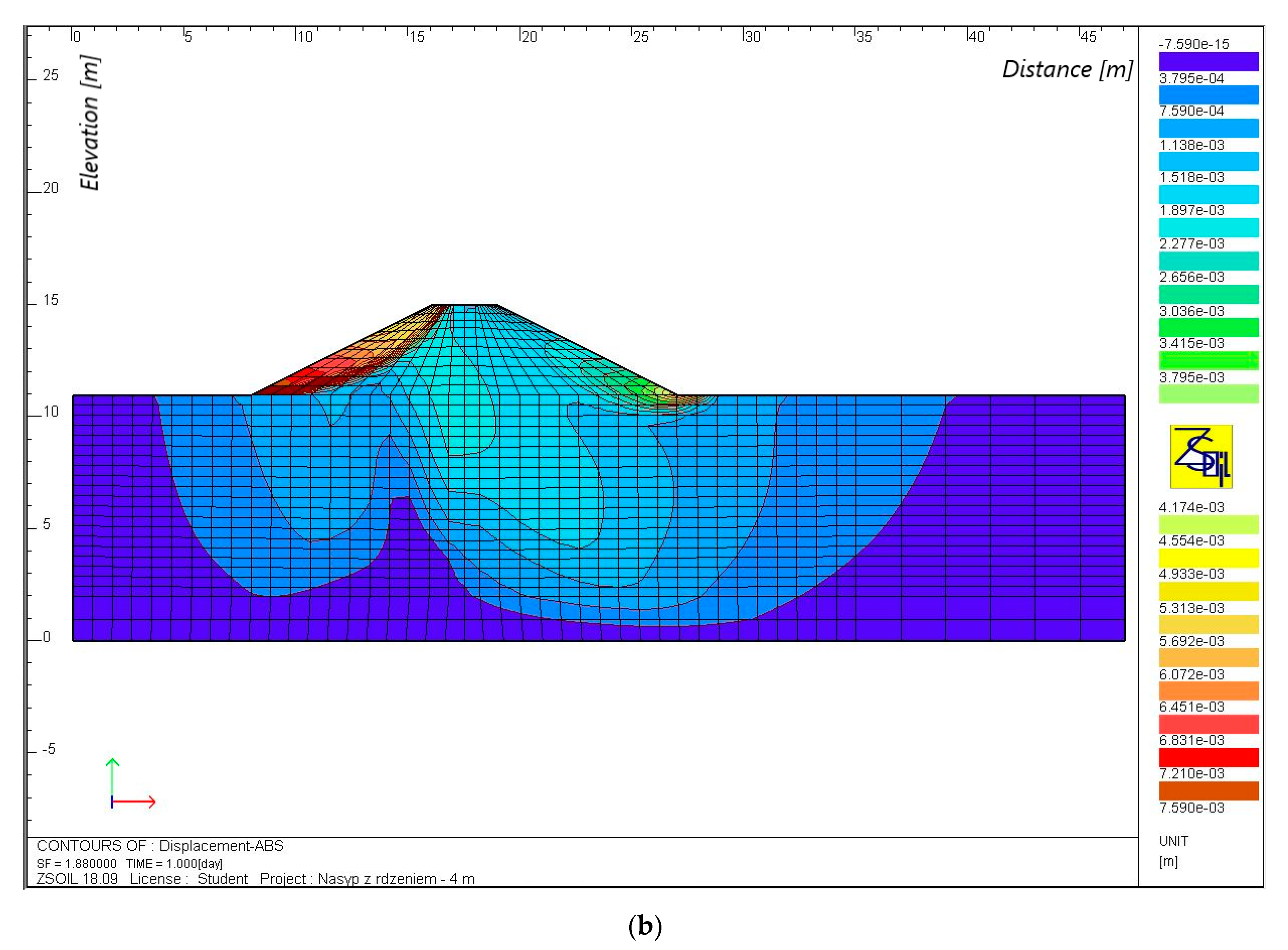
The results of stability calculations of the slopes of the analyzed embankments, depending on the backwater (with and without continuous backwater) and the type of embankment (with and without a seal) are shown in Table 4. For the case without backwater, the factor of safety was 1.4 at any height of the embankment, with or without a seal. This follows from the assumption that the slope material is composed of medium sand, for which zero cohesion was assumed in the calculations. For each embankment height, the smallest factor of safety was obtained for the slip surfaces, which were at low depths, located parallel to the edge of the slope, with a surface landslide occurring in each case. The factor of safety was higher than that required (FS ≥ 1.3), so, in the absence of backwater, medium sands with the adopted parameters can be used for the construction of embankment slopes with the selected gradient to a height of 8 m.
The calculation results for the case with continuous backwater show significant differences between the factor of safety of the upstream and downstream slopes, depending on the height of the embankment and whether the seal was used or not (Table 4). These values for upstream slopes increased from 1.48 to 1.67 (embankment without a core), and from 1.45 to 1.52 (embankment with a core), as the height of the embankment increased from 4 to 8 m. For downstream slopes, there was an inverse relationship, and the stability factor decreased from 1.17 to 0.96 and 0.87 (embankment without a core) and from 1.38 to 1.32 and 1.26 (embankment with a core), with the height of the embankment increasing from 4 to 6 and 8 m. As can be seen, the downstream slope of the embankment without a core with heights of 6 and 8 m was unstable, and at a height of 4 m, the factor of safety was less than required.
Based on calculations using the Bishop’s method, it can be said that in conditions without backwater, the use of a core made of bottom sediment from the Rzeszow reservoir had no effect on the stability of the embankment. In the case of continuous backwater, an embankment without a core retained stability only at a height of 4 m, wherein the value of the stability factor was less than that required (FS = 1.17). For embankments with a height of 6 and 8 m, the factor of safety of downstream slopes was smaller than 1, so the slope was unstable.

3.3.2. FEM Method

Calculations for the case without backwater indicate that stability is maintained for both an embankment with and without a core at each adopted embankment height. The factor of safety ranged from 1.8 to 1.6 and did not show variability, depending upon the type of the embankment (Table 5). As in the case of the Bishop’s method, this results from the parameters of the material (cohesion value of zero), so the yield zones are shallow and parallel to the slope surface.
Calculations for the case with continuous backwater (Table 5, Figure 6 and Figure 7) also indicate that the stability of both embankments was maintained. The potential slip curves for the embankment without a core and with a core, with a height of 8 m, occurred on the downstream side, whereas, in the case of an embankment with a core with heights of 4 and 6 m, the soil yielded as a result of displacement caused by the reduction of the strength parameters. The factor of safety decreased from 1.7 to 1.2 for the embankment without a core and from 1.9 to 1.7 for the embankment with a core, as the height of the embankment increased from 4 to 8 m, respectively. Therefore, the use of a core resulted in a 1.2-fold (on average) increase in the value of the factor of safety.
Calculations for the case with a passing of a flood wave (Table 5, Figure 8) indicate that both embankments maintained stability. For the calculations carried out at a maximum backwater (t = 5 d), the potential slip curves occurred as in the case with continuous backwater, with the exception of an embankment with a core, with a height of 4 m, where the movement occurred on both sides of the embankment. The results of the calculations after the water level drops indicate that the potential slip curves for an embankment with a core appear on the upstream slope, and for an embankment without a core, on both sides of the embankment. After 3 days of maximum backwater (t = 5 d), there was a steady filtration; hence, the factors of safety at the maximum backwater (t = 5 d) were the same as for the case with continuous backwater, while in the descending phase (t = 7 d) they decreased from about 2.1 to 1.9 (embankment without a core) and from 2.1 to 1.7 (embankment with a core), as the height of the embankment increased from 4 to 8 m. The size of seepage on the downstream side was slightly lower than for the conditions of continuous backwater (Table 5).
In the case of calculations simulating the passage of a flood wave, the stability of the embankment was similar as in the case of continuous backwater, while in the descending phase, the values of the stability factor for upstream slopes in each calculation case met the requirement of FS ≥ 1.3 [52]. Seepage on the downstream side of the embankment was similar as in the case of continuous backwater, so the use of a core had a corresponding effect on the stability conditions of these embankments.
Based on these results. it can be stated that in conditions without backwater, both an embankment without a core and an embankment with a core maintain stability. The resulting stability factors were high and comparable for the two types of embankments adopted; the use of a core therefore did not affect the conditions of stability. In the case of calculations with continuous backwater, lower values of the factor of safety were obtained, which, however, guaranteed the stability of the slopes and were higher than the value required by [52] for the Classes III and IV of embankments.

3.4. Summary and Discussion of the Results

The values of the factor of safety of slopes that were determined using numerical methods were generally consistent with those obtained using the limit equilibrium method. In all calculation cases, the values of the factor of safety that were obtained using the analytical method were smaller than those obtained using the numerical method; it can thus be stated that this method provides a greater safety margin. It was a non-cohesive slope, so the critical failure surface in the Bishop’s method was shallow, and the factor of safety was lower. The biggest differences occurred in the case of an embankment without a core with heights of 6 and 8 m with continuous backwater; according to the analytical method, the slopes in this embankment were unstable, and in the numerical method, the factors of safety were 1.4 and 1.2 respectively. These differences arose from different assumptions made in the above methods. In the analytical method, the loss of stability for the assumed slip curve occurs if the forces maintaining the balance of the rigid body are smaller than the sliding forces (a component of the weight of the given block, tangential to the slip surface, is greater than the friction and cohesion of the soil), while in the numerical method, the determination of the yielding point results from the analysis of stress distribution in the given soil medium. The advantage of the Bishop’s method is the speed and simplicity of the calculations, and in the case of simple structures, such as hydraulic engineering embankments in the technical Classes III and IV, it may be successfully used to determine stability conditions. On the other hand, finite element calculations do not require the assumption of the shape of the slip surface in advance, and allow the determination of the development of plastic strain with the progressive reduction of strength parameters, until the formation of a plastic strain zone, which determines the course and shape of the potential slip surface.
Dams of reservoirs are an obstacle to mineral material transported by rivers. This causes the development of the landing processes of these reservoirs. The high degree of overloading of the Rzeszów reservoir prompted the authors to carry out research aimed at recognizing the geotechnical properties of the sediments deposited in the reservoir. In the available literature, there are few publications on research related to the possibility of using bottom sediments for earth construction purposes. Research on the properties of bottom sediments is most often carried out in the aspect of assessing the content and migration of heavy metals [55,56] or organic pollutants [57,58]. On the other hand, the potential use of bottom sediments is seen in agriculture for the fertilization and reclamation of post-industrial areas [22,23,24,59]. Therefore, the problem presented in the article is important from the point of view of environmental engineering. The authors carried out a series of tests and numerical calculations in terms of the use of bottom sediments for earth construction purposes. The performed calculations indicate the potential possibilities of using bottom sediments in applications related to hydrotechnical construction.

4. Conclusions

Based on the suitability analysis of bottom sediments from the Rzeszow reservoir for civil engineering, it was concluded that this material can be used for sealing elements in hydraulic engineering embankments. The obtained values of geotechnical parameters of the sediments show that this material fulfills most of the criteria required to use them in sealing layers. The calculations of stability and filtration through the embankments in this regard confirmed the usefulness of the analyzed sediments. An embankment made of medium sand, with a core made of bottom sediments maintained stability at a height of 8 m; the values of the stability factor in each calculation case were greater than that required by regulation. By using a core made of bottom sediment, the volume of seepage on the downstream side during continuous or variable backwater was significantly lower in relation to an embankment without a core, and the phreatic line did not extend to the downstream slope.
It is estimated that in the case of a planned dredging in the Rzeszow reservoir, the amount of dredged sediments could exceed 1.5 million m3; therefore, the possibility of their economic use, as indicated above, is essential. The tests and calculations carried out allowed the determination of the possible use of bottom sediments in civil engineering. As a result, the sediments could provide an alternative to natural soil, whose resources are limited and non-renewable. The search for materials that could replace natural soil in earthen structures is a very important issue from both the ecological and economic points of view.

Author Contributions

Conceptualization, K.K., A.G. and E.Z.; methodology, K.K.; software, K.K.; validation, A.G. and K.K.; formal analysis, K.K. and A.G.; investigation, A.G. and K.K.; resources, K.K.; data curation, K.K.; writing—original draft preparation, K.K. and A.G.; writing—review and editing, A.G. and K.K.; visualization, K.K. and A.G.; supervision, A.G.; project administration, A.G.; funding acquisition, A.G. All authors have read and agreed to the published version of the manuscript.

Funding

This research received no external funding.

Institutional Review Board Statement

Not applicable.

Informed Consent Statement

Not applicable.

Conflicts of Interest

The authors declare no conflict of interest.

References

  1. Sobczak, J. Zapory z Materiałów Miejscowych; PWN: Warszawa, Poland, 1975. [Google Scholar]
  2. Flores-Berrones, R.; López-Acosta, P. Internal Erosion due to Water Flow through Earth Dams and Earth Structures. In Soil Erosion; Godone, D., Stanchi, S., Eds.; IntechOpen: Rijeka, Croatia, 2011; pp. 283–306. [Google Scholar] [CrossRef] [Green Version]
  3. U.S. Society on Dams. Materials for Embankment Dams; Prepared by the USSD Committee on Materials for Embankment Dams; U.S. Society on Dams: Denver, CO, USA, 2011. [Google Scholar]
  4. Bednarczyk, S.; Jarzębińska, T.; Mackiewicz, S.; Wołoszyn, E. Vademecum ochrony przeciwpowodziowej; Krajowy Zarząd Gospodarki Wodnej: Gdańsk, Poland, 2006. [Google Scholar]
  5. Park, J.; Son, Y.; Noh, S.; Bong, T. The suitability evaluation of dredged soil from reservoirs as embankment material. J. Environ. Manag. 2016, 183, 443–452. [Google Scholar] [CrossRef]
  6. Ipsita, P.; Surabhi, J.; Sarat, K.; Jayabalan, R. Characterization of red mud as a structural fill and embankment material using bioremediation. Int. Biodeterior. Biodegrad. 2017, 119, 368–376. [Google Scholar] [CrossRef]
  7. Zydroń, T.; Gruchot, A. Influence of Moisture and Compaction on Shear Strength and Stability of Embankments from Ash-Slag Mixture. (In Polish: Wpływ wilgotności i zagęszczenia na wytrzymałość na ścinanie popioło-żużli i stateczność budowanych z nich nasypów). Annu. Set Environ. Prot. Rocznik Ochrony Środowiska 2014, 16, 498–518. [Google Scholar]
  8. Gruchot, A. Utilisation of Coal Mining Wastes and Fuel Ashes for Engineering Purposes as a Factor of Environmental Development and Protection. (In Polish: Utylizacja Odpadów Powęglowych i Poenergetycznych do Celów Inżynierskich Jako Czynnik Kształtowania i Ochrony środowiska); Zeszyty Naukowe (Rozprawy), 410; Uniwersytet Rolniczy im. Hugona Kołłątaja: Kraków, Poland, 2016; p. 533. [Google Scholar]
  9. Gwóźdź, R. Geotechnic properties of sediment deposited in the Rożnowskie lake and the possibility of using it in municipal waste disposal site soil construction. (In Polish: Właściwości geotechniczne osadów zdeponowanych w jeziorze rożnowskim oraz możliwości ich wykorzystania do budowy przesłon mineralnych w składowiskach odpadów komunalnych). Czasopismo Techniczne-Środowisko 2008, 1, 13–23. [Google Scholar]
  10. Dysarz, T.; Wicher-Dysarz, J. Analysis of Flow Conditions in the Stare Miasto Reservoir Taking into Account Sediment Settling Properties. Annu. Set Environ. Prot. Rocznik Ochrony Środowiska 2013, 15, 584–605. [Google Scholar]
  11. Łajczak, A. Studium nad Zamulaniem Wybranych Zbiorników Zaporowych w Dorzeczu Wisły; Monografie Komitetu Gospodarki Wodnej PAN; Oficyna Wydawnicza PWN, Zeszyt 8: Warszawa, Poland, 1995. [Google Scholar]
  12. Batuca, G.D.; Jordaan, M.J. Silting and Desilting of Reservoirs; A.A. Balkema: Rotterdam, The Netherlands, 2000. [Google Scholar]
  13. Journal of Laws. Dz.U. z 2014 r., poz. Rozporządzenie Ministra Środowiska z dnia 9 grudnia 2014 r. w sprawie katalogu odpadów. 1923. Available online: https://dziennikustaw.gov.pl/DU/rok/2014/pozycja/1923 (accessed on 10 September 2020).
  14. Journal of Laws. Dz.U. z 2013 r., poz. 21. Ustawa z dnia 14 grudnia 2012 r. o odpadach z późniejszymi zmianami. Available online: https://dziennikustaw.gov.pl/DU/rok/2013/pozycja/21 (accessed on 10 September 2020).
  15. Sojka, M.; Siepak, M.; Gnojska, E. Assessment of heavy metal concentration in bottom sediments of Stare Miasto pre-dam reservoir on the Powa River. (In Polish: Ocena zawartości metali ciężkich w osadach dennych wstępnej części zbiornika retencyjnego Stare Miasto na rzece Powie). Annu. Set Environ. Prot. Rocznik Ochrona Środowiska 2013, 15, 1916–1928. [Google Scholar]
  16. Zhang, Y.; Zhang, X.; Bi, Z.; Yu, Y.; Shi, P.; Ren, L.; Shan, Z. The impact of land use changes and erosion process on heavy metal distribution in the hilly area of the Loess Plateau, China. Sci. Total Environ. 2020, 718. [Google Scholar] [CrossRef] [PubMed]
  17. Augustyniak, R.; Grochowska, J.; Łopata, M.; Parszuto, K.; Tandyrak, R. Characteristics of bottom sediments in polish lakes with different trophic status. In Polish River Basins and Lakes—Part I. The Handbook of Environmental Chemistry; Korzeniewska, E., Harnisz, M., Eds.; Springer: Cham, Switzerland, 2020; p. 86. [Google Scholar] [CrossRef]
  18. Baran, A.; Tarnawski, M.; Kaczmarski, M. Assessment of agricultural utilization of bottom sediments from the Besko reservoir. Czasopismo Techniczne 2011, 108, 3–11. [Google Scholar]
  19. Szara, M.; Baran, A.; Klimkowicz-Pawlas, A.; Tarnawski, M. Ecotoxicological characteristics and ecological risk assessment of trace elements in the bottom sediments of the Rożnów reservoir (Poland). Ecotoxicology 2020, 29, 45–57. [Google Scholar] [CrossRef] [PubMed]
  20. Szal, D.; Gruca-Rokosz, R. Anaerobic oxidation of methane in freshwater sediments of Rzeszów reservoir. Water 2020, 12, 398. [Google Scholar] [CrossRef] [Green Version]
  21. Wiśniowska-Kielian, B.; Niemiec, M. Effect of bottom sediment addition to the substratum on the quality of produced maize biomass. Ecol. Chem. Eng. 2007, 14, 581–589. [Google Scholar]
  22. Fonseca, R.M.; Barriga, F.; Fyfe, W.S. Reversing desertification by using same reservoir sediments as agriculture soils. Episodes 1998, 21, 218–224. [Google Scholar] [CrossRef] [Green Version]
  23. Canet, R.; Chaves, C.; Pomares, R.; Alibach, R. Agricultural use of sediments from the Albufera Lake (eastern Spain). Agric. Ecosyst. Environ. 2003, 95, 29–36. [Google Scholar] [CrossRef]
  24. Baran, A.; Jasiewicz, C.; Tarnawski, M. Effect of bottom desposit on trace element content in light soil. Ecol. Chem. Eng. 2010, 17, 1553–1561. [Google Scholar]
  25. Tarnawski, M.; Baran, A.; Koniarz, T.; Wyrębek, M.; Grela, J.; Piszczek, M.; Koroluk, A. The possibilities of the environmental use of bottom sediments from the silted inlet zone of the Rożnów Reservoir. Geol. Geophys. Environ. 2017, 43, 335–344. [Google Scholar] [CrossRef]
  26. Pelczar, J.; Loska, K.; Melaniuk, E. Wpływ nawożenia osadem dennym na aktywność enzymatyczną zwałowiska odpadów węgla kamiennego. Arch. Ochr. Śr. 1998, 24, 93–101. [Google Scholar]
  27. Koś, K. Charakterystyka geotechniczna osadów dennych cofki Zbiornika Czorsztyńskiego i możliwości ich wykorzystania do celów budownictwa ziemnego. Inżynieria Morska i Geotechnika 2013, 2, 135–143. [Google Scholar]
  28. Bounouara, Z.; Malab, S.; Mekerta, B.; Benaissa, A.; Bourokba, S.A. Treatment of Dredged Sediments of Bouhanifia Dam for Their Valorization in Passive Barrier of Landfill. Geotech. Geol. Eng. 2020, 38, 3997–4011. [Google Scholar] [CrossRef]
  29. Koś, K.; Zawisza, E. Stabilization of bottom sediments from Rzeszowski Reservoir. Ann. Warsaw Univ. Life Sci.—SGGW Land Reclam. 2015, 47, 127–137. [Google Scholar] [CrossRef] [Green Version]
  30. Chiang, K.-Y.; Chien, K.-L.; Hwang, S.-J. Study on the characteristics of building bricks produced from reservoir sediment. J. Hazard. Mater. 2008, 159, 499–504. [Google Scholar] [CrossRef]
  31. Becker, A.; Bucher, F.; Davenport, C.A.; Flisch, A. Geotechnical characteristics of post-glacial organic sediments in Lake Bergsee, southern Black Forest, Germany. Eng. Geol. 2004, 74, 91–102. [Google Scholar] [CrossRef]
  32. Kataoka, S.; Yamashita, S.; Kawaguchi, T.; Suzuki, T. The Soil Properties of Lake-Bottom Sediments in the Lake Baikal Gas Hydrate Province. Soils Found. 2009, 49, 757–775. [Google Scholar] [CrossRef]
  33. Ballas, G.; Garziglia, S.; Sultan, N.; Pelleter, E.; Toucanne, S.; Marsset, T.; Riboulot, V.; Ker, S. Influence of early diagenesis on geotechnical properties of clay sediments (Romania, Black Sea). Eng. Geol. 2018, 240, 175–188. [Google Scholar] [CrossRef] [Green Version]
  34. Madeyski, M.; Michalec, B.; Tarnawski, M. Silting of Small Water Reservoirs and Quality of Sediments. (In Polish: Zamulanie Małych Zbiorników Wodnych i Jakość Osadów Dennych); Infrastuktura i Ekologia Terenów Wiejskich (Infrastructure And Ecology Of Rural Areas); Polska Akademia Nauk: Kraków, Poland, 2008. [Google Scholar]
  35. Polski Komitet Normalizacyjny. PN-EN ISO 14688-2:2006. Badania Geotechniczne. Oznaczanie i Klasyfikowanie Gruntów. Część 2: Zasady Klasyfikowania; Polski Komitet Normalizacyjny: Warszawa, Poland, 2006. [Google Scholar]
  36. Polski Komitet Normalizacyjny. PN-EN ISO 17892-4:2017-01. Rozpoznanie i Badania Geotechniczne. Badania Laboratoryjne Gruntów. Część 4: Badanie Uziarnienia Gruntów; Polski Komitet Normalizacyjny: Warszawa, Poland, 2017. [Google Scholar]
  37. Polski Komitet Normalizacyjny. PN-EN ISO 17892-3:2016-03. Rozpoznanie i Badania Geotechniczne. Badania Laboratoryjne Gruntów. Część 3: Badanie Gęstości Właściwej; Polski Komitet Normalizacyjny: Warszawa, Poland, 2016. [Google Scholar]
  38. Polski Komitet Normalizacyjny. PN-EN ISO 17892-12:2018-08. Rozpoznanie i Badania Geotechniczne. Badania Laboratoryjne Gruntów. Część 12: Oznaczanie Granic Płynności i Plastyczności; Polski Komitet Normalizacyjny: Warszawa, Poland, 2018. [Google Scholar]
  39. Polski Komitet Normalizacyjny. PN-EN 13286-2:2010. Mieszanki Niezwiązane i Związane Hydraulicznie. Część 2: Metody Badań Laboratoryjnych Gęstości na Sucho i Zawartości Wody. Zagęszczanie Metodą Proktora; Polski Komitet Normalizacyjny: Warszawa, Poland, 2010. [Google Scholar]
  40. Polski Komitet Normalizacyjny. PN-EN ISO 17892-10:2019-01. Rozpoznanie i Badania Geotechniczne. Badania Laboratoryjne Gruntów. Część 10: Badania w Aparacie Bezpośredniego Ścinania; Polski Komitet Normalizacyjny: Warszawa, Poland, 2019. [Google Scholar]
  41. Polski Komitet Normalizacyjny. PN-B-04481:1988. Grunty Budowlane. Badania Próbek Gruntu; Polski Komitet Normalizacyjny: Warszawa, Poland, 1988. [Google Scholar]
  42. GeoStudio. Stability Modeling with GeoStudio; GEO-SLOPE International LTD.: Calgary, AB, Canada, 2020. [Google Scholar]
  43. Truty, A.; Podles, K. User Developments in ZSoil®; ZSoil®.PC 200101 Report; Zace Services Ltd., Software Engineering: Lausanne, Switzerland, 2020. [Google Scholar]
  44. Cała, M.; Flisiak, J.; Tajduś, A. Numerical methods of slope stability analysis (In Polish: Numeryczne metody analizy stateczności skarp i zboczy). In Materiały Sympozjum Warsztaty Górnicze z Cyklu “Zagrożenia Naturalne w Górnictwie”, Bełchatów; Polska Akademia Nauk. Instytut Gospodarki Surowcami Mineralnymi i Energią: Bełchatów, Poland, 2004; pp. 34–50. [Google Scholar]
  45. Baran, P.; Grodecki, M. Strength and strain parameters of colliery spoils in the light of laboratory tests and numerical analyses. (In Polish: Parametry wytrzymałościowe i odkształceniowe odpadów powęglowych w świetle badań laboratoryjnych i analiz numerycznych). Wydawnictwo Politechniki Śląskiej Zeszyty Naukowe Budownictwo 2003, 98, 15–22. [Google Scholar]
  46. Żurek, A.; Czop, M. Modelling of water flow and precipitation chemistry transformation during infiltration process in the lysimeter experiment. (In Polish: Modelowanie warunków przepływu i przekształceń składu chemicznego wód opadowych w trakcie procesu infiltracji, na przykładzie doświadczenia lizymetrycznego). Biuletyn Państwowego Instytutu Geologicznego Hydrogeologia 2010, 442, 181–188. [Google Scholar]
  47. Van Genuchten, M.T. A closed form equation for predicting the hydraulic conductivity of unsaturated soils. Am. Soc. Soil Sci. 1980, 44, 892–898. [Google Scholar] [CrossRef] [Green Version]
  48. Arya, L.M.; Paris, J.F. A physico-empirical model to predict the soil moisture characteristic from particle-size distribution and bulk density data. Soil Sci. Soc. Am. J. 1981, 45, 1023–1030. [Google Scholar] [CrossRef]
  49. Aubertin, M.; Mbonimpa, M.; Bussire, B.; Chapuis, R.P. A model to predict the water retention curve from basic geotechnical properties. Can. Geotech. J. 2003, 40, 1104–1122. [Google Scholar] [CrossRef]
  50. Yang, X.; You, X. Estimating Parameters of Van Genuchten Model for Soil Water Retention Curve by Intelligent Algorithms. Appl. Math. Inf. Sci. 2013, 7, 1977–1983. [Google Scholar] [CrossRef] [Green Version]
  51. Borys, M.; Zawisza, E.; Gruchot, A.; Chmielowski, K. River embankments. In Open Channel Hydraulics, River Hydraulic Structures and Fluvial Geomorphology: For Engineers, Geomorphologists and Physical Geographers; Radecki-Pawlik, A., Pagliara, S., Hradecký, J., Eds.; CRC Press: Florida, USA, 2018; pp. 133–167. [Google Scholar]
  52. Journal of Laws. Dz.U. z 2007 r., nr 86, poz. 579. Rozporządzenie Ministra Środowiska z dnia 20 kwietnia 2007 r. w sprawie warunków technicznych, jakim powinny odpowiadać budowle hydrotechniczne i ich usytuowanie. 2007. Available online: https://dziennikustaw.gov.pl/DU/2007/s/86/579 (accessed on 10 September 2020).
  53. Koś, K.; Zawisza, E. Geotechnical characteristics of bottom sediments from Rzeszowski reservoir. (In Polish: Charakterystyka geotechniczna osadów dennych zbiornika Rzeszowskiego). J. Civil Eng. Environ. Archit. Czasopismo Inżynierii Lądowej Środowiska i Architektury 2015, 62, 195–208. [Google Scholar] [CrossRef]
  54. Polski Komitet Normalizacyjny. PN-B-12095:1997. Urządzenia Wodno-Melioracyjne. Nasypy. Wymagania i Badania Przy Odbiorze; Polski Komitet Normalizacyjny: Warszawa, Poland, 2016. [Google Scholar]
  55. Szarek-Gwiazda, E.; Czaplicka-Kotas, A.; Szalińska, E. Background Concentrations of Nickel in the Sediments of the Carpathian Dam Reservoirs (Southern Poland). Clean Soil Air Water 2011, 39, 368–375. [Google Scholar] [CrossRef]
  56. Kulbat, E.; Sokołowska, A. Methods of Assessment of Metal Contamination in Bottom Sediments (Case Study: Straszyn Lake, Poland). Arch. Environ. Contam. Toxicol. 2019, 77, 605–618. [Google Scholar] [CrossRef] [PubMed] [Green Version]
  57. Mazurkiewicz, J.; Mazur, A.; Mazur, R.; Chmielowski, K.; Czekała, W.; Janczak, D. The Process of Microbiological Remediation of the Polluted Słoneczko Reservoir in Poland: For Reduction of Water Pollution and Nutrients Management. Water 2020, 12, 3002. [Google Scholar] [CrossRef]
  58. Ziemińska-Stolarska, A.; Imbierowicz, E.; Jaskulski, M.; Szmidt, A. Assessment of the Chemical State of Bottom Sediments in the Eutrophied Dam Reservoir in Poland. Int. J. Environ. Res. Public Health 2020, 17, 3424. [Google Scholar] [CrossRef] [PubMed]
  59. Fonseca, R.; Barriga, F.J.A.S.; Fyfe, W.S. Suitability for Agricultural Use of Sediments from the Maranhão Reservoir, Portugal. In Optimization of Plant Nutrition; Developments in Plant and Soil Sciences, 53; Fragoso, M.A.C., Van Beusichem, M.L., Houwers, A., Eds.; Springer: Dordrecht, The Netherlands, 1993. [Google Scholar] [CrossRef]
Figure 1. Schematic diagram of the cross-section of a levee, including the main elements [4]. (1)—upstream slope, (2)—downstream slope, (3)—crest, (4)—tight screen, (5)—tight core, (6)—subsoil ground sealing, (7)—drain, (8)—drainage ditch, (9)—depression curve in the case of a homogeneous embankment (without core). (a)—safety reserve, (b)—levee crest width, (1:n)—upstream slope inclination, (1:m)—downstream slope inclination.
Sustainability 13 01221 g001
Figure 2. Location and view of the Rzeszów reservoir.
Sustainability 13 01221 g002
Figure 3. Diagram for stability calculations of the embankment made with medium sand and sealed with a core made of bottom sediments.
Sustainability 13 01221 g003
Figure 4. Grain size composition of the bottom sediments from the Rzeszów reservoir.
Sustainability 13 01221 g004
Figure 5. Location of the phreatic line and water pressure distribution in soil pores—embankment with a height of 6 m without a core (a) and with a core (b) (pressure in kPa).
Sustainability 13 01221 g005
Figure 6. Movement isolines for FEM grid nodes for an embankment with a height of 4 m, without a core (a) and with a core (b), with continuous backwater.
Sustainability 13 01221 g006aSustainability 13 01221 g006b
Figure 7. The phreatic line for an embankment with a height of 4 m, without a core (a) and with a core (b), with continuous backwater.
Sustainability 13 01221 g007aSustainability 13 01221 g007b
Figure 8. Movement isolines for FEM grid nodes at maximum backwater (a) and after the falling of the wave (b), for an embankment with a height of 4 m, with a core made of sediment at the passing of a flood wave.
Sustainability 13 01221 g008
Table 1. Geotechnical parameters of bottom sediments from the Rzeszów reservoir and soils adopted for stability calculations.
ParameterValue for Material:
Bottom Sediments—Silt (Si), Is = 0.95Medium Sand (MSa),
ID = 0.8
Clay (Cl), IL = 0.2
Angle of internal friction [°]22.33518
Cohesion [kPa]42.7030
Unit weight [kN·m−3]20.118.621
Coefficient of permeability [m·s−1]3.4 × 10−91 × 10−41 × 10−10
Voids ratio [–]0.8430.5650.422
where: IS—compaction index [–], ID—degree of compaction [–], IL—plasticity index [−].
Table 2. Geotechnical parameters of bottom sediments from the Rzeszów reservoir in comparison with the requirements for sealing elements in hydraulic engineering structures.
ParameterRequirementsValue for the Bottom Sediments
Coefficient of uniformity, Cu>1513.3
Clay fraction content, Cl [%]<308.5
Content of particles smaller than 0.005 mm, [%]10 ÷ 2519
Content of particles smaller than 0.01 mm, [%]>2530
Organic matter content, [%]<2 ÷ 33.33
Coefficient of permeability, [m·s−1]<10−81.05 × 10⁻⁸ (IS = 0.9)
1.2 × 10⁻⁹ (IS = 1)
Table 3. Results of filtration calculations.
ConditionsEmbankmentHeight of embankment [m]
468
Height of maximum water level [m]
2.54.56.5
Maximum leakage Q [m3 × (d·m)−1] for:
bodysubsoiltotalbodysubsoiltotalbodysubsoiltotal
With continuous backwaterWithout a core1.286.137.413.3615.9219.387.2824.8232.1
With a core0.663.794.451.28.49.591.1512.0913.24
With variable backwaterWithout a core1.296.067.352.916.0118.917.5624.8132.36
With a core0.793.814.61.288.259.520.8812.0212.9
Table 4. The results of stability calculations using the Bishop’s method.
Height of Embankments [m]SlopeConditions
Without BackwaterWith Continuous Backwater
Embankment
Without a CoreWith a CoreWithout a CoreWith a Core
Factor of Safety, FS [–]
4Upstream1.4031.4031.4761.451
Downstream1.1741.379
6Upstream1.4031.4031.6111.477
Downstream0.9581.321
8Upstream1.4021.4021.671.522
Downstream0.8661.255
Table 5. Results of embankment stability calculations using the FEM method.
ConditionsEmbankmentHeight of the Embankment [m]
468
Factor of safety, FS [–]
Without backwaterWithout a core1.831.681.63
With a core1.761.681.63
With continuous backwaterWithout a core1.721.431.22
With a core1.881.811.67
With variable backwaterAt maximum backwater (t = 5 d)Without a core1.721.431.22
With a core1.891.811.68
After the drop of the flood wave (t = 7 d)Without a core2.121.971.88
With a core2.071.981.74
Publisher’s Note: MDPI stays neutral with regard to jurisdictional claims in published maps and institutional affiliations.

