Article

An Investigation of Suitable Healing Agents for Vascular-Based Self-Healing in Cementitious Materials

Magnel-Vandepitte Laboratory, Department of Structural Engineering and Building Materials, Faculty of Engineering and Architecture, Ghent University, Technologiepark Zwijnaarde 60, B-9052 Ghent, Belgium
*
Author to whom correspondence should be addressed.
Sustainability 2021, 13(23), 12948; https://doi.org/10.3390/su132312948
Submission received: 26 October 2021 / Revised: 19 November 2021 / Accepted: 21 November 2021 / Published: 23 November 2021
(This article belongs to the Special Issue Sustainability and Green Construction)

Abstract

:
Self-healing cementitious materials can extend the service life of structures, improve safety during repair activities and reduce costs with minimal human intervention. Recent advances in self-healing research have shown promise for capsule-based and intrinsic healing systems. However, limited information is available regarding vascular-based self-healing mechanisms. The aim of this work is to compare different commercially available healing agents regarding their suitability in a self-healing vascular network system by examining a regain in durability and mechanical properties. The healing agents investigated include sodium silicate, two polyurethanes, two water repellent agents and an epoxy resin. Sealing efficiencies above 100% were achieved for most of the healing agents, and both polyurethanes and the epoxy resin showed high regain in strength. The results obtained from this study provide a framework for selecting a healing agent given a specific application, as a healing agent’s rheology and curing properties can affect the optimal geometry and design of a vascular network.

1. Introduction

Cracking in concrete is inevitable due to its inherent brittle nature, and this opens pathways for aggressive substances to damage reinforcement and deteriorate the overall structure. Allowing concrete to self-heal can reduce material consumption as well as result in cost savings for maintenance and repair activities. Additionally, self-healing can extend the service life of concrete as well as lessen the environmental impact of cement production. To date, several self-healing mechanisms have been explored across multiple fields of research and can be generally categorized into three groups: intrinsic, capsule-based and vascular-based [1]. Several initial life cycle analyses on intrinsic and capsule-based self-healing systems have been performed, indicating that they are a more sustainable solution than traditional repair methods [2,3,4,5].
Most intrinsic and capsule-based self-healing systems can be easily incorporated in a concrete mix without being severely damaged, while vascular networks require more care to avoid brittle failure during casting (e.g., vibrating the concrete mix in localized areas, utilizing a self-consolidating mix design). However, vascular networks have the advantage over intrinsic and capsule-based self-healing methods because they are available for multiple healing cycles and have the ability to be pressurized, further increasing their healing efficiency. Investigations in healing agent selection for vascular networks have been limited thus far because the development of vascular self-healing systems specifically designed for cementitious materials is still in the proof-of-concept stages of research.
A number of suitable healing agents for vascular networks have been used before for concrete in capsule-based or injection repair methods. Epoxy resins can be applied for self-healing in either one- or two-component systems, and both have been demonstrated in a number of capsule-based self-healing systems for cementitious materials [6,7,8]. Generally, one-component epoxy resins require higher temperatures to polymerize and have shorter shelf lives compared to two-component epoxy resins (a few months vs. 12 months). An advantage of a vascular system is that an adequate mixing of two components can be easily done prior to supplying it through a network, while this is not guaranteed with a capsule-based system. Van Tittelboom studied different epoxy resins from Prime Resins in [9] and found that Prime Rez 1100, in particular—whose main component is a bisphenol-A-(epichlorhydrin) epoxy resin—indicated a good tolerance for wet conditions as well as chemical resistance with a relatively lower temperature limit, of 0 °C, for curing. This would make it more suitable for varying weather or cooler environments, and as a two-component epoxy it does not require higher temperatures to cure. While other adhesives such as cyanoacrylate have been used as a healing agent for laboratory-scale concrete beams with vascular self-healing [10,11], epoxy resins have not been studied so far for this application. However, they have been explored in polymeric matrices with embedded vascular networks [12,13,14].
Some mineral compounds such as soluble silicates (also referred to as “water-glass”) have microstructures and properties that are similar to those of the cement matrix and can be a cost-effective alternative to epoxy resins. They chemically interact with excess calcium hydroxide (CH) in the cement matrix when exposed to water, forming insoluble calcium silicate hydrate (C-S-H) gels, and have been successfully demonstrated in capsule-based and vascular self-healing cementitious materials [15]. Sodium silicate, in particular, has been of interest in research, as it has shown a better recovery in durability compared to other silicates. Tests on sodium silicate in [16] showed its suitability as a healing agent, with load recovery in a three-point bending set-up ranging between 66 and 76% of its original strength. In most studies, the self-healing efficiencies using sodium silicate are tested after 28 days of curing [17,18,19].
Foaming agents such as polyurethane have been employed for cementitious self-healing vascular systems in addition to capsule-based systems with a demonstrated potential for repeated healing [20,21] as well as sealing characteristics [22,23]. Polyurethane can be used either as a one- or a two-component healing agent. An expansive foaming reaction with a volume increase of up to 25–30 times occurs upon a contact with moisture that enables the polyurethane to travel further throughout a crack and allows for better crack filling.
Water repellent agents (WRAs) typically contain an active silane (SiH4) compound, and once it penetrates the concrete pores it reacts with hydrated cement to form a silicon resin that acts as a hydrophobic coating along the pore walls, helping to prevent chloride and water ingress [24,25]. WRAs have not yet been demonstrated in vascular applications, but their low viscosities (<10 mPa.s) are an attractive characteristic, as they can be easily pumped through a complex network configuration. In addition, due to its hydrophobic nature, the fluid only needs to come into contact with the crack faces to coat the surface rather than fill the crack in order to fully seal it. The drawback of WRAs is that they generally will not increase the mechanical properties of damaged concrete, as they only provide a coating to prevent water ingress.
One of the main gaps in research on self-healing cementitious materials, especially in vascular-based systems, is the lack of a selection strategy for healing agents. A number of suitable candidates have been studied, but not with the aim of comparing multiple types of healing agents and selecting an optimal one for a particular application. Additionally, a healing efficiency is typically defined differently between studies. The novelty of this work is that multiple healing agents are evaluated together, and the computation of their healing efficiencies is critically examined given the varying nature of crack formation in concrete, thereby yielding more knowledge to select a healing agent. This work aims to compare commercially available healing agents and quantify their potential for regain in durability and mechanical properties, while accounting for the unique crack patterns for each individual sample. Each of the selected healing agents in this study has varying curing mechanisms and viscosities, and thus their potential for repeated healing will also be explored, as this is another criterion for an efficient vascular-based self-healing system.

2. Materials and Methods

2.1. Selected Healing Agents

The commercially available healing agents selected for this study are summarized in Table 1. The shelf lives are reported for each of the different healing agents; however, this would not have a large impact on the healing agent selection, as the supply can be replenished on an as-needed basis. Additionally, their costs can be used to estimate the cost of the repair and maintenance works via the application of the self-healing system. It is noted that the costs listed in Table 1 for each healing agent are an approximation and can vary depending on the quantity ordered. The healing agents were additionally considered for their curing times; curing times below one minute would be too fast for pumping purposes.
Lower-viscosity healing agents are preferable for the ease of pumping through a network and to allow multiple healing cycles to be obtained, as they are less likely to block the vascular channels; however, the pressure of a system can be adjusted for higher-viscosity healing agents. The viscosity of each of the healing agents was measured at 1000 s−1 with a concentric cylinder rheometer (Anton Paar MCR 102, observational error of 5%).

2.2. Concrete Mix Properties

Concrete beams with dimensions of 60 × 60 × 220 mm3 were cast using a self-consolidating mix composition, specified in Table 2. The effectiveness of the healing agents was assessed in a capillary water absorption test set-up, and this beam size was chosen for the ease of handling during the test [26]. A total of three repetitions were included for each type of healing agent investigated (the code name for each healing agent is listed in Table 1), as well as for a series of uncracked (REF UNCR) and cracked (REF CR) reference specimens. The mix used CEM I 52.5 N cement with a water to cement ratio of 0.45 and limestone filler with a particle size < 125 µm. Aggregates no larger than 8 mm were included so that they would easily pass between the glass network and the walls of the mold. To improve workability and allow the fresh concrete to flow around the vascular network, a superplasticizer was included in the mix design (Master Glenium 27 concentration of 20%, BASF, Waterloo, Belgium).
One batch of concrete was prepared in a vertical shaft mixer with a capacity of 50 L and rotating pan (Eirich, Germany). After the dry components were mixed for 1 min, water was added and mixing continued for 3 min. The superplasticizer was added 30 s after the water was added. A first layer of fresh concrete was slowly added around the glass tubes (see Section 2.3) to ensure there were no voids underneath the glass networks, after which the remaining fresh concrete was added. To ensure the mix was fully compacted in the molds, the molds were vibrated on a vibrating table at a low speed for no more than 20 s.
The slump flow, density and air content were determined on the fresh concrete, and 150 × 150 × 150 mm3 cubes were cast to determine the compressive strength. These tests on the mix yielded a slump flow of 57.5 cm, an average density of 2341 kg/m3 and an air content of 2.5%. The compressive strength at 28 days was 80.25 MPa, with a standard deviation of 1.14 MPa.
After casting, the specimens were stored in a curing room with a temperature of 20 °C and a relative humidity of >95%. The specimens were demolded one day after casting and immediately placed back in the curing environment until testing.
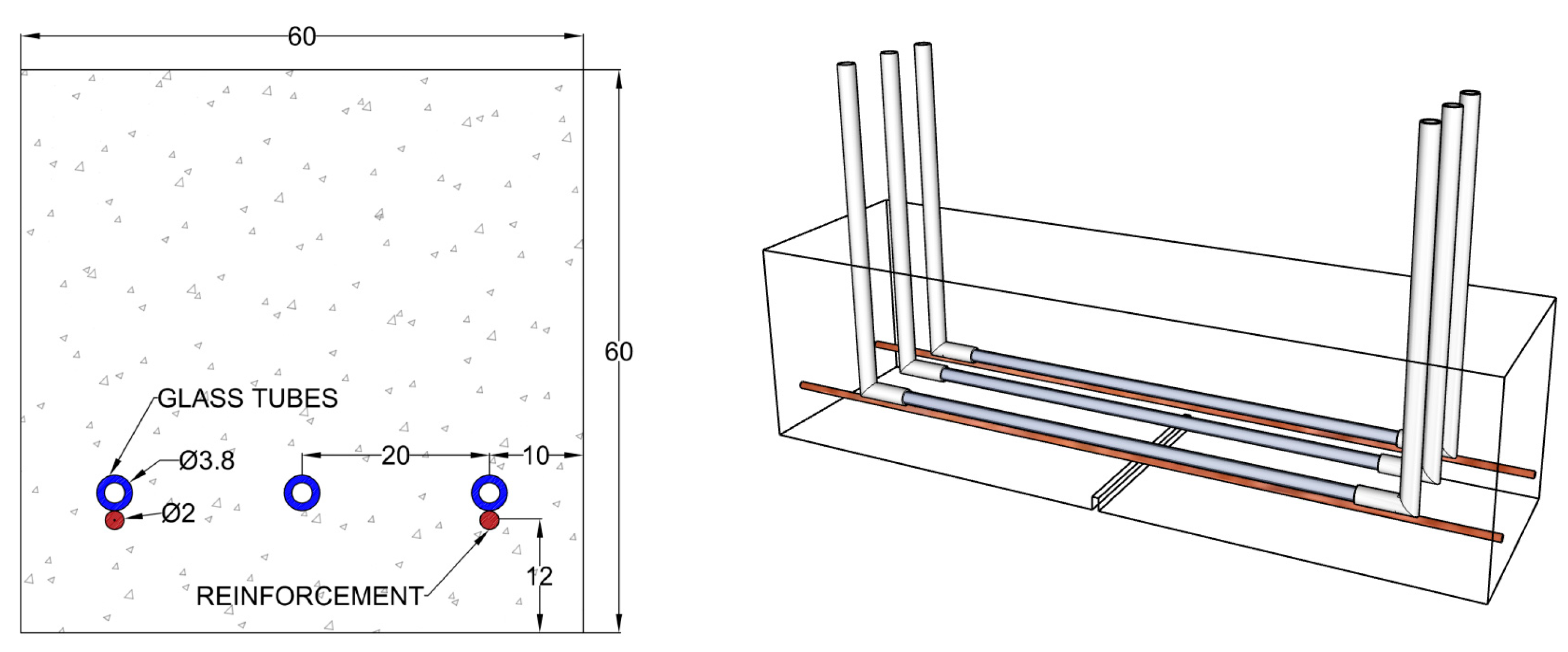
Two copper-coated steel wires with a diameter of 2.0 mm were added (Figure 1) to achieve a realistic loading behavior as well as prevent a total failure of the beams during loading. The wires were manually sanded to promote bonding to the concrete matrix.
A linear vascular system, rather than an optimized configuration, was chosen to assess the performance of the individual healing agents in this study. Three glass tubes with a length of 150 mm, an outer diameter of 3.8 mm and a wall thickness of 0.8 mm were placed in the molds equally spaced on spacers, so that they rested just above the reinforcement. The ends of the glass tubes were connected to silicone tubes to facilitate the healing-agent pumping, and the beams were notched at their midspan on the bottom side with a saw cutter to a depth of 4 mm after curing (Figure 1).

2.3. Preliminary Investigation of the Surface Treatment of the Vascular System

Glass tubes were chosen as the network channels for this study, as they are typically chemically inert. Before testing the different healing agents, different surface treatments for the glass tubes were investigated to help quantify their bonding to the cement matrix (Figure 2) and verify that they would fracture along with the concrete, a crucial requirement for a brittle network in self-healing concrete. Three repetitions for each glass surface treatment were fabricated: sand blasted, manually sanded and no surface treatment.
A single glass tube was embedded in 60 × 60 × 220 mm3 notched beams, which were prepared according to the mix design, the specimen dimensions and the procedure outlined in Section 2.3, and tested after two weeks of curing. A separate batch of concrete was prepared to cast these specimens, and the tests on the mix yielded a slump flow of 55.0 cm, an average density of 2367 kg/m3 and an air content of 2.4%. The compressive strength at 28 days was 75.04 MPa, with a standard deviation of 1.57 MPa.
Similarly to the specimens shown in Figure 1, the glass tube was connected to silicone tubes on either side of the ends to allow the fluid to be pumped through (Figure 3), with openings placed instead along the sides of the beam, rather than using three tubes with openings on the top of the sample. While one end of the tubes was closed, water was pumped through until approximately 1.5 bar of pressure was achieved, at which point the tube was closed off on the inlet side. After two weeks of curing, the samples were subjected to a three-point bending test with a span of 190 mm using a universal load frame (Instron Model 5982). The crack opening rate was controlled via crack mouth opening displacement (CMOD) with a rate of 0.7 µm/s, and the CMOD was recorded when water appeared on the surface of the crack.

2.4. Activation of the Self-Healing Mechanism

After two weeks of curing, the samples mentioned in Section 2.3 for the final tests were loaded in three-point bending to generate a crack. Loading was controlled using CMOD at the midspan of the beam with a rate of 0.7 µm/s and a span of 190 mm using a universal load frame (Instron Model 5982). During loading, the test was extended until a CMOD reading of 0.4 mm was achieved, so that upon unloading the specimen, the relaxed crack width would reach approximately 0.3 mm. Serviceability-sized cracks range between 0.1 and 0.4 mm as per EN 1992-1-1 [27]. After crack formation, microscopic images were taken using a Leica DMC 2900 microscope at three locations along the crack to measure the width as well as for a visual comparison before and after healing; five crack width measurements were taken at each location and used to provide an average crack width per specimen.

2.5. Evaluation of the Self-Healing Efficiency

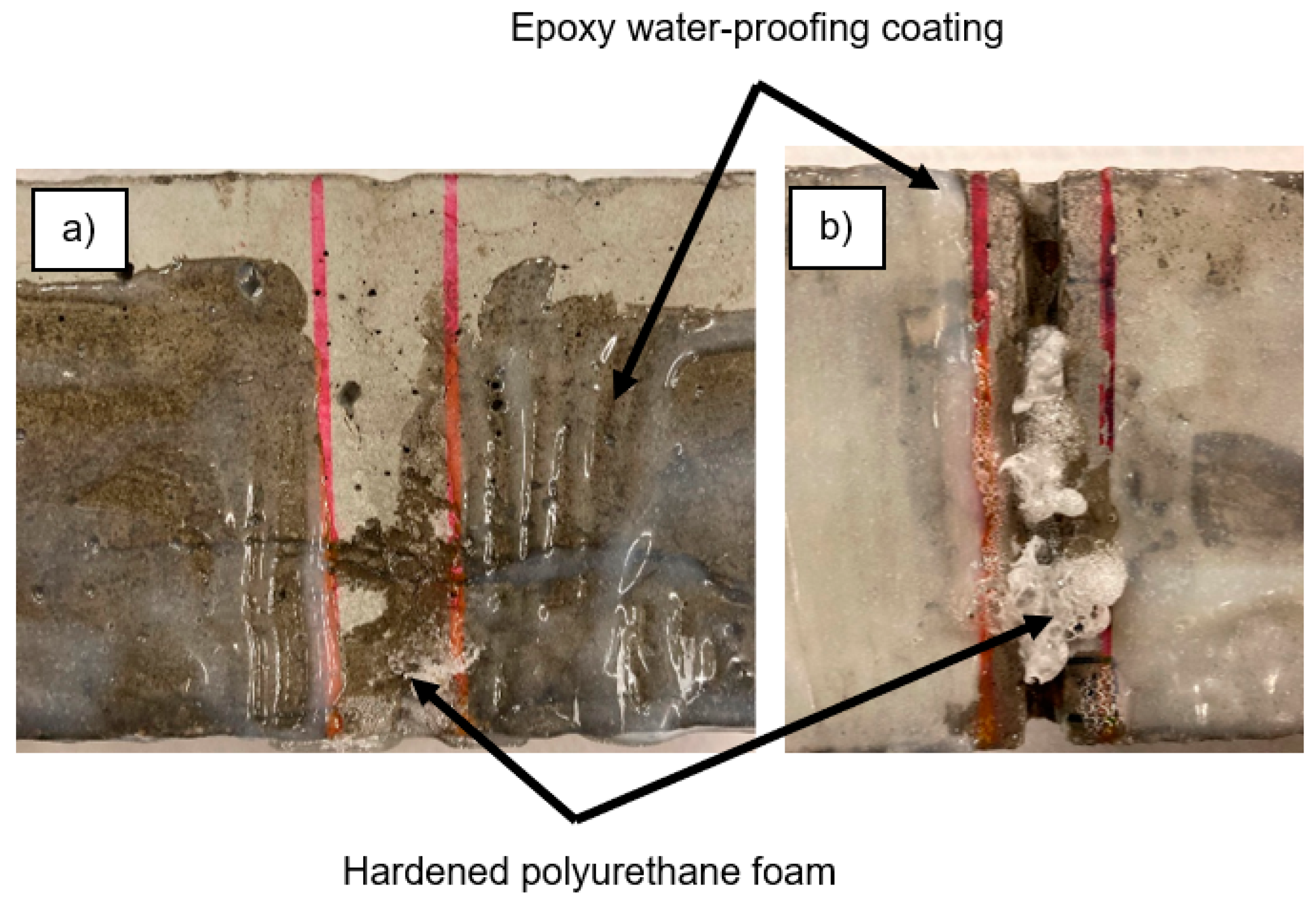
Two capillary water absorption tests were performed, one before and one after supplying a healing agent through the network. After crack formation, the cracked and uncracked specimens were placed in an oven at 40 ± 5 °C until constant mass was achieved, which occurred after 5 days. The standard EN 13057 defines constant mass as a weight change not greater than 0.2% in 2 h. This may not be a strict enough criterion; therefore, constant mass in this study was defined as having no more than a 0.1% difference over a 24-h period. The samples were then removed from the oven, and two coatings of an epoxy resin sealer were applied with a brush, keeping a 14-mm exposed strip centered on the crack along the bottom and the sides of the specimen. The sides of the specimen were covered up to a height of 40 mm (except for the strip centered on the crack). The two-component epoxy resin sealer, Episol® Designtop SF [28], was used to waterproof the samples to allow for more homogeneous results for this test [29]. The samples were first dried without an epoxy coating until they reached constant mass. The epoxy coating was then applied, and once cured, the samples were returned to the oven at 40 ± 5 °C for a minimum of 5 days until constant mass was achieved again.
During the capillary water absorption test, the cracked specimens were set on two non-absorbing supports in a box containing water, so that they were immersed in water 3 ± 1 mm above the notch. The specimens were weighed to determine the weight gain with time after 10 min, 20 min, 30 min, 1 h, 1 h 30 min, 2 h, 3 h, 4 h, 6 h, 8 h and 24 h. A pre-wetted cloth was used to remove any excess moisture on the surface of the specimen before recording its mass. An instruction video produced by an interlaboratory study for this procedure is provided in [30].
After the first water absorption test, the samples were dried again for a minimum of 10 days until constant mass was achieved. They were then pumped with a healing agent, and a second water absorption test was executed in the following day. An exception was made for the sodium silicate samples, as they have a longer curing time. While most studies suggest a curing time of 28 days for sodium silicate to allow it to react with calcium hydroxide (CH) in the cement matrix when exposed to water and form calcium silicate hydrate (C-S-H) gels, during this experimental campaign this healing agent was observed to have hardened after 24 h. While this hardening could be considered a healing product, it did not appear to have fully reacted with the cementitious matrix. These samples were healed immediately after the first water absorption test to allow the excess water to aid in the reaction, and then stored in an oven (40 ± 5 °C) for a total of 40 days prior to their second water absorption test. A 28-day curing period was originally planned for these samples. However due to unforeseen repair works involving the laboratory equipment, the curing and drying period for these samples were extended to 40 days. This separate series also included its own set of cracked and uncracked reference samples.
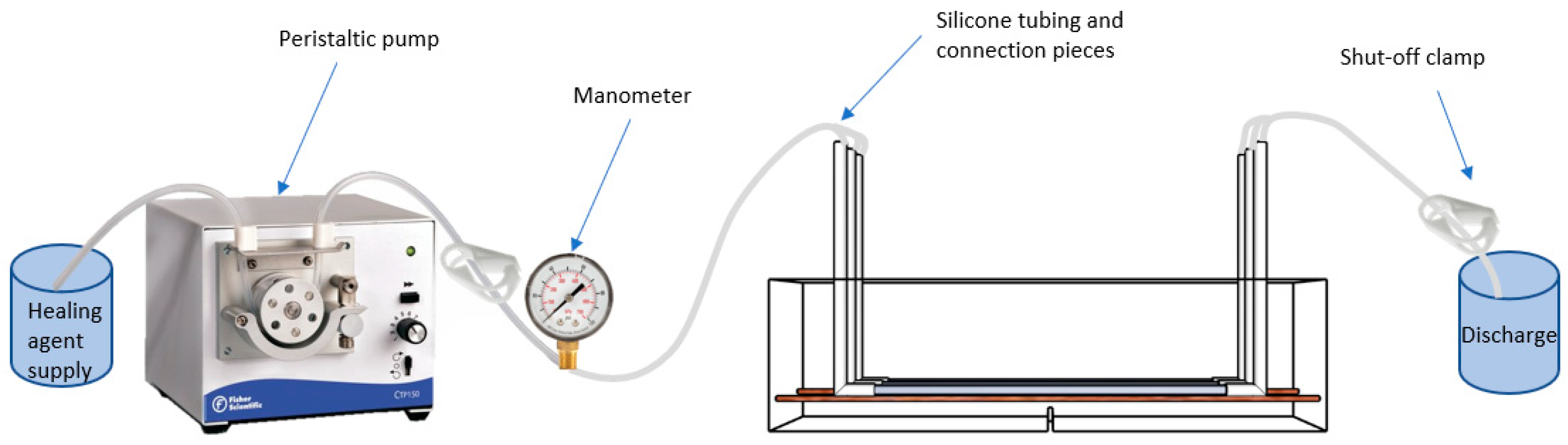
A peristaltic pump (Fisherbrand pump model #CTP150) (Figure 4) was chosen for administering the healing agent to eliminate the possibility of cross-contamination among healing agents; the pumping action relies on positive displacement within the interchangeable tubes to move the fluid through the system.
For each specimen with a supplied healing agent, the fluid was pumped at a low rate until the fluid was seen coming out of the outlet, at which point the valve was shut at the outlet. Pumping was left on until a pressure of 1.5 bar was reached, or until any flow was seen coming from the crack mouth, at which point the valve at the inlet was shut. The pressure gauge was monitored for two minutes while visually checking for seepage around the crack and at the bottom of the specimen. After the two minutes, both valves were released and air was pumped through the silicone tubes until any remaining fluid inside the glass tubes of the vascular network was flushed out as much as possible.
It was investigated if the network channels were blocked after a healing cycle, and verified if any additional healing agent could still be pumped through the network. This was achieved by pumping water through the embedded networks in the beams, which done immediately before the second loading test (and well beyond the curing of the agents). An additional series of specimens were used to pump a healing agent (using PU1) through the network and subsequently flushed out with a high-pressure air compressor (up to 6 bar) to investigate the effect of a high-pressure flushing procedure, and if it would reduce the amount of hardened healing agent blocking the channels. Water was also flushed through these samples as previously described.
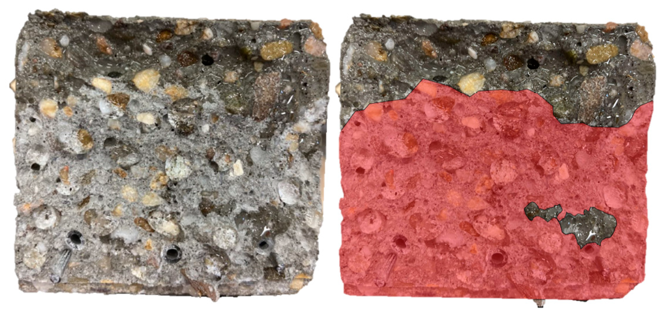
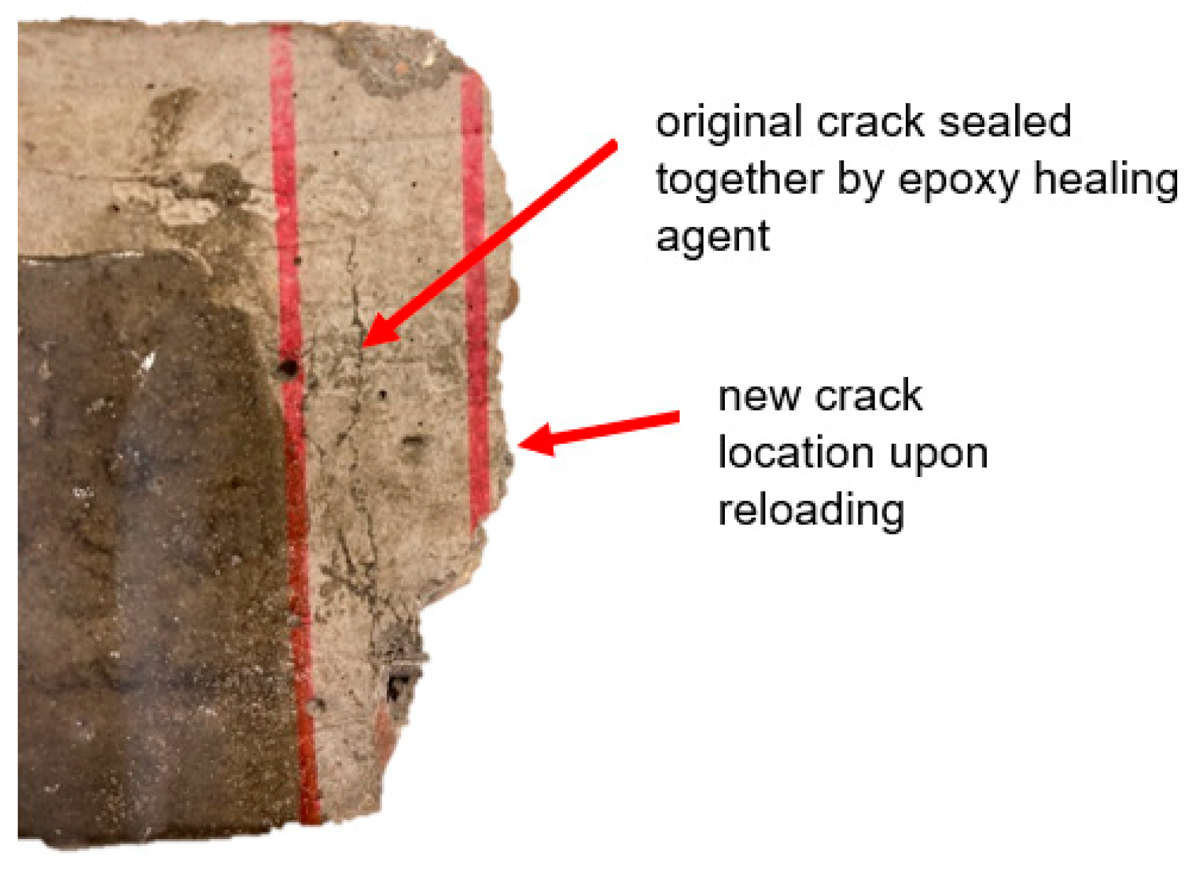
Three days after the second capillary water absorption test, the samples were reloaded under the same loading scheme so that a regain in mechanical strength could be evaluated. Once complete, the samples were completely broken to investigate the spread of the fluid on the crack surfaces.
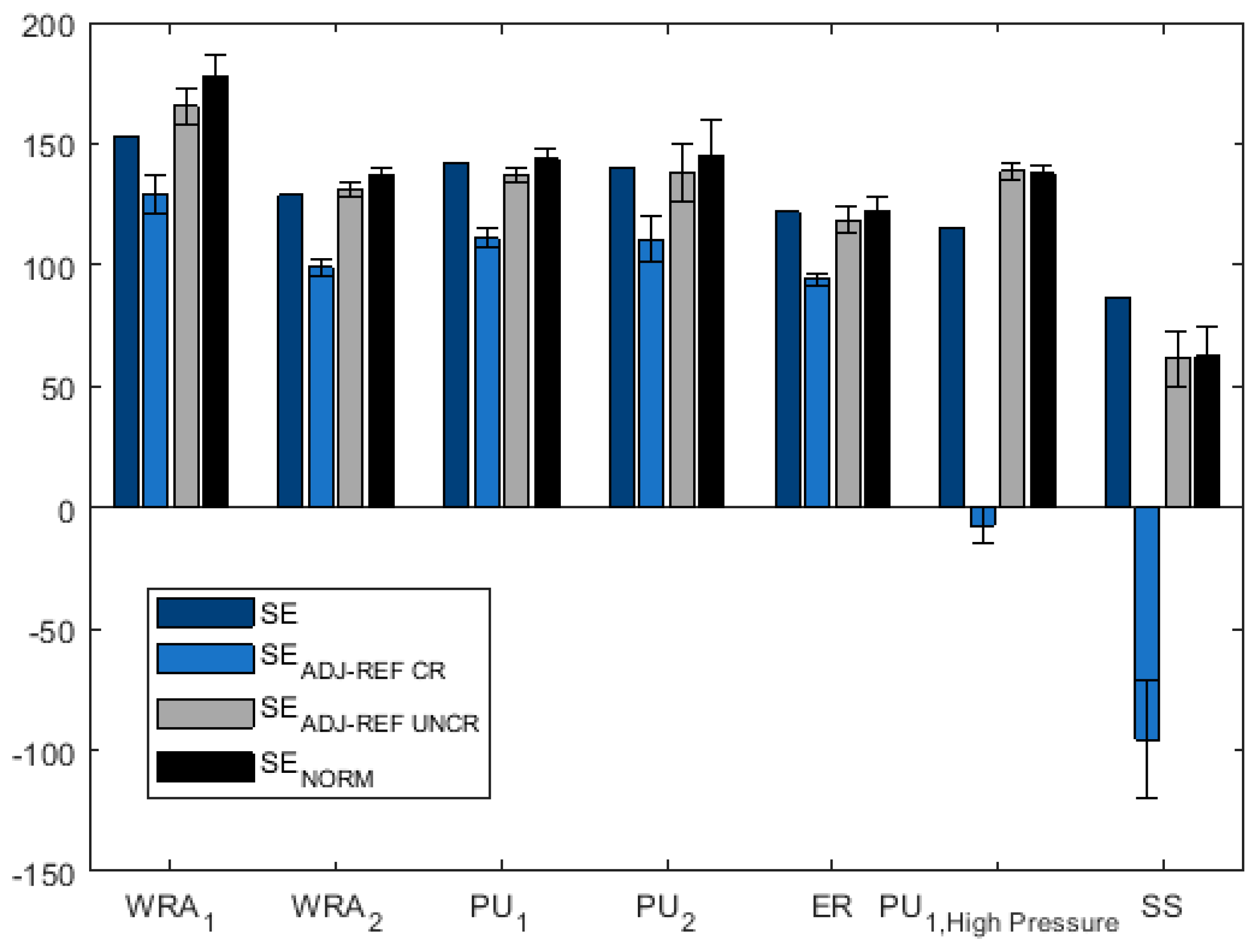
Different methods of calculating the sealing efficiency (SE) are explored in this paper. Typically, it is defined as a percentage by the following equation [26]:
SE = SC ¯ REF   CR SC ¯ Healed SC ¯ REF   CR SC ¯ REF   UNCR × 100 %
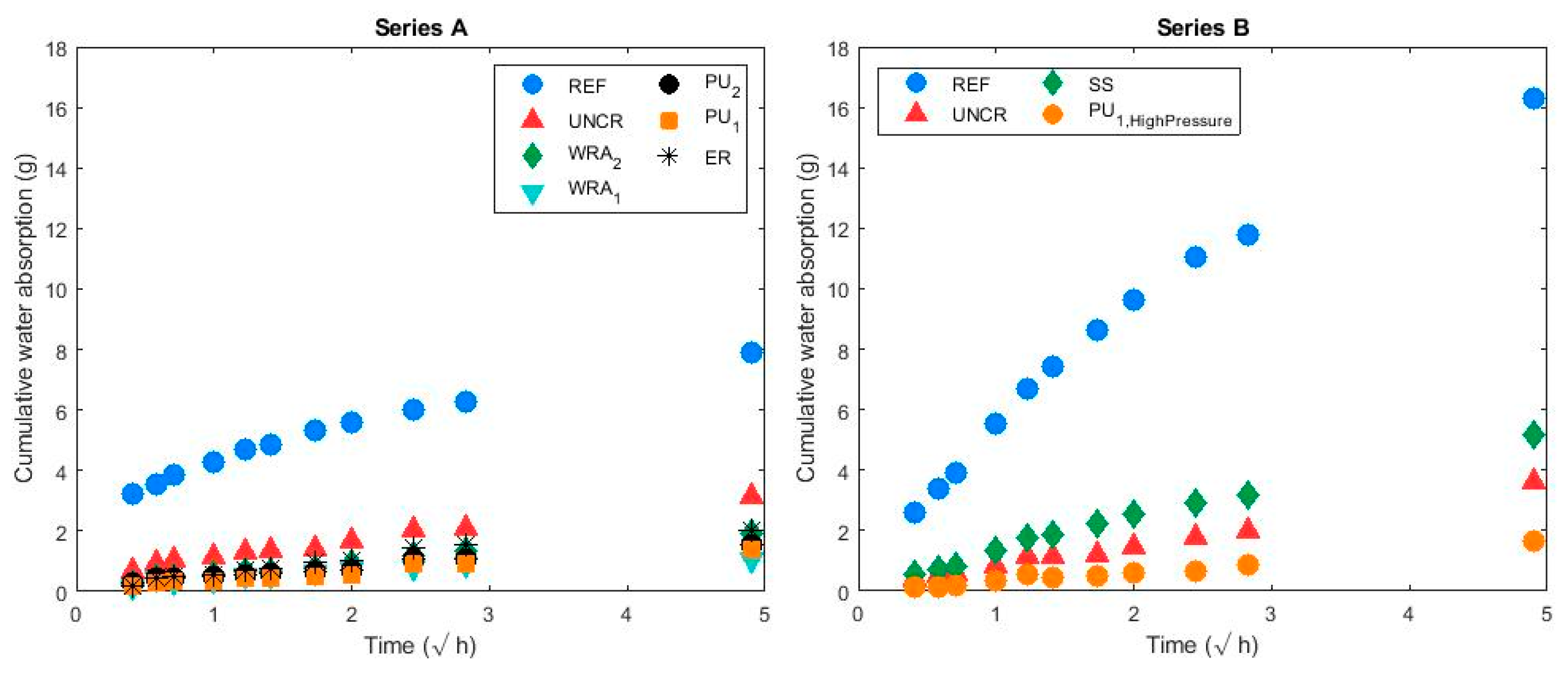
where SC represents a sorption coefficient obtained by the linear slope line for the cumulative mass gain over the square root of time graphs; all values for this equation would be taken from the second water absorption test. SC ¯ REF   CR represents the average SC of the cracked reference series (g/√h), SC ¯ REF   UNCR represents the average SC of the uncracked reference series (g/√h) and SC ¯ Healed represents the average SC of the healed specimens (g/√h).
Since performing two water absorption tests (one before and one after healing) allows for a comparison of unique individual samples before and after healing, an adjustment in the sealing efficiency calculation can be done. For this study, two groups of samples (A and B) were included to (1) allow for a longer curing period for the sodium silicate specimens, (2) investigate the effect of a longer drying period on the sealing efficiency calculations, and (3) verify that pumping a healing agent at a higher pressure to flush out the networks would not negatively impact the sealing and healing efficiency. Series A included samples healed with PU1, PU2, ER, WRA1 and WRA2. As mentioned previously, the drying period prior to each capillary water absorption test was 10 days. Series B included samples healed with SS and PU1; PU1 was flushed out at a pressure of approximately 6 bar. For Series B, the drying period for the first water absorption test was 10 days, and for the second test it was 40 days.
Since a difference in sorption coefficients was observed for all samples between the two water absorption tests, a correction factor would be needed to calculate the sealing efficiency more accurately when two tests are performed. The second sealing efficiency calculation is proposed in Equation (2) as SEADJ-REF CR (%), which uses SC values from the first water absorption test, but incorporates a linear adjustment factor   ( SC ¯ REF   CR ,   1 st   test SC ¯ REF   CR ,   2 nd   test ) in the SCHealed, 2nd test value based on the change with time in average SCs for the cracked reference samples:
SE ADJ REF   CR =   SC Unhealed ,   1 st   test ( SC Healed ,   2 nd   test + ( SC ¯ REF   CR ,   1 st   test SC ¯ REF   CR ,   2 nd   test ) ) SC Unhealed ,   1 st   test SC ¯ REF   UNCR ,   1 st   test × 100 %
where SCUnhealed, 1st test represents the SC for an unhealed sample during the first water absorption test (g/√h), SCHealed, 2nd test represents the SC during the second water absorption test (which is performed after the sample had been healed (g/√h)), SCREF CR, 1st test represents the average SCs of the cracked reference specimens during the first water absorption test (g/√h), SCREF CR, 2nd test represents the average SCs of the cracked reference specimens during the second water absorption test (g/√h) and SCREF UNCR, 1st test represents the average SCs of the reference uncracked samples during the first water absorption test (g/√h).
Equation (3) is similar to Equation (2), but uses the difference between the SCs of the uncracked specimens   ( SC ¯ REF   UNCR ,   1 st   test SC ¯ REF   UNCR ,   2 nd   test ) to adjust the SCHealed, 2nd test value rather than the cracked specimens to investigate its suitability as a correction factor:
SE ADJ REF   UNCR =   SC Unhealed ,   1 st   test ( SC Healed ,   2 nd   test + ( SC ¯ REF   UNCR ,   1 st   test SC ¯ REF   UNCR ,   2 nd   test ) ) SC Unhealed ,   1 st   test SC ¯ REF   UNCR ,   1 st   test × 100 %  
where SCREF UNCR, 2nd test represents the average SCs of the reference uncracked samples during the second water absorption test (g/√h).
An additional correction method would be to normalize the sorption coefficient values rather than reduce them by a linear factor. Equation (4), SENORM, is similar to the original equation to calculate sealing efficiencies (Equation (1)), except that each SC is normalized by the average SC of the uncracked samples for the same test (i.e., the SCunhealed values would be normalized by the SCUNCR from the first water absorption test, and SChealed values would be normalized by the SCUNCR from the second test).
SE NORM =     SC Unhealed , 1 st   test SC UNCR ,   1 st   test SC Healed ,   2 nd   test SC UNCR , 2 nd   test SC Unhealed ,   1 st   test SC UNCR ,   1 st   test 1 × 100 %
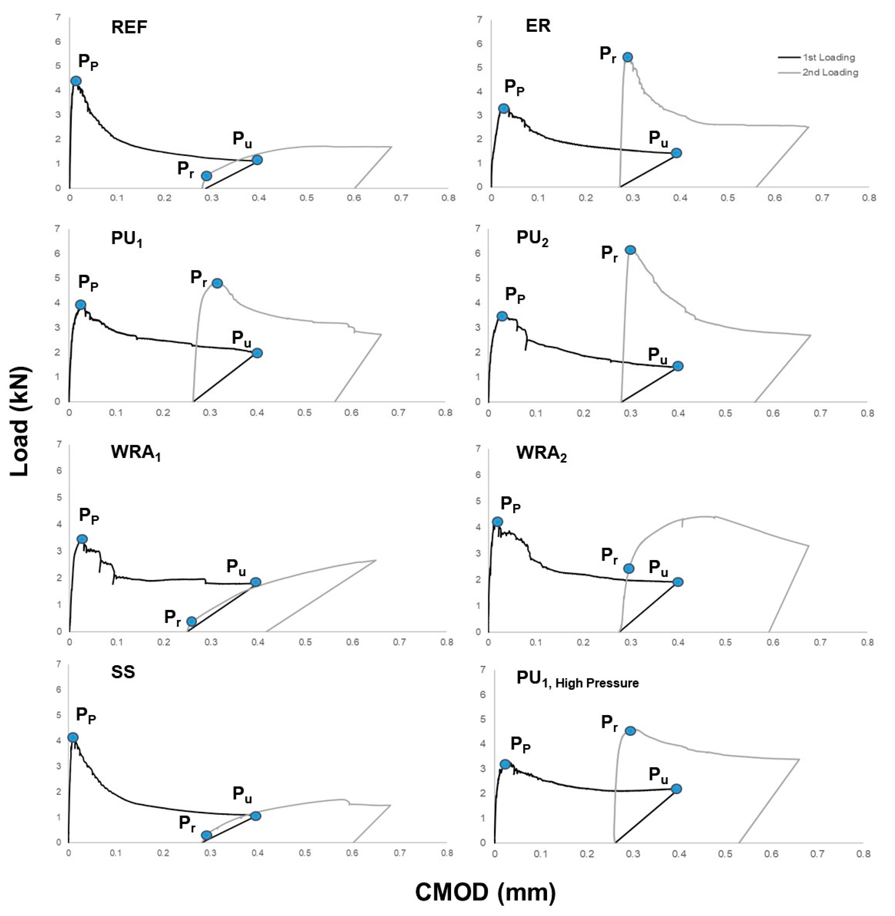
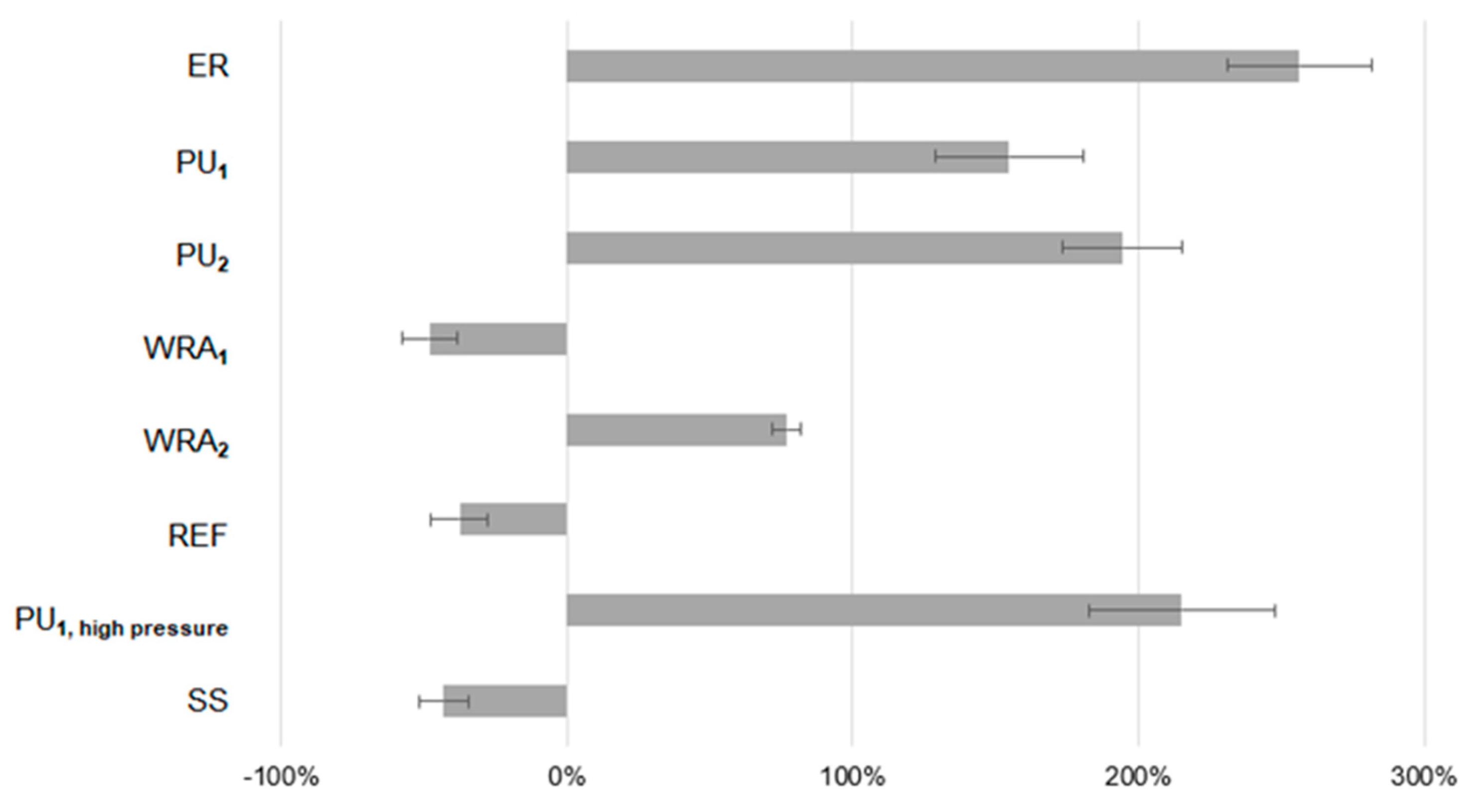
The recovery in strength was evaluated by a load regain index (LRI) defined by [31,32] as:
LRI   ( % ) = P r P u P p P u × 100 %
where Pr (kN) is the peak (maximum) load attained during reloading, Pp (kN) is the peak load during the first loading and Pu (kN) is the residual load obtained at the moment of unloading during the first loading cycle. If no clear peak was achieved upon reloading, Pr was taken to be the load at the point along the curve where the slope started to reduce (illustrated graphically in Section 3.2).

3. Results and Discussion

3.1. Preliminary Test on the Surface Treatment Suitability for Glass Vascular Networks

The specimens with embedded water-filled sand-blasted glass tubes visually showed more surface roughness, improving the bond with the cementitious matrix. As such, it was expected that the sandblasted samples showed water at the surface of the crack mouth at an average 0.046 mm CMOD and hand-sanded samples at a greater CMOD of 0.065 mm. No treatment showed water release at a CMOD of 0.079 mm. It was confirmed that with sandblasting, the tubes break at an earlier point in the bending test and thus exhibit greater bonding than the other two alternatives. They are therefore selected as the treatment of the glass tubes for the final tests.

3.2. Mechanical Load Regain

Load versus CMOD charts are given for representative samples of each of the different healing agents in Figure 5. It is important to note that an increase in peak load upon reloading does not necessarily indicate healing, but could be the result of the steel bars being pulled, and thus of the yielding of the reinforcement. Therefore, Pr was taken to be the load at the point along the curve where the slope started to reduce, for if the maximum values were taken for the reference (REF) sample in Figure 5 rather than the load where the slope of the curve starts to change, it would be reporting a load regain value of 18%, based on Equation (5).
Figure 6 includes the results of the load regain index calculations. High load regains (>150%) are achieved for ER, both polyurethanes and even some load regain for WRA2. A higher load regain is noted for the PU1, high pressure which was flushed out with air at a high pressure after healing relative to PU1. Enhanced healing could have occurred due to the polyurethane being pushed even further throughout the crack.
The flexural strength of the specimens with and without embedded tubes were computed and are listed in Table 3, with n representing the number of samples, µ the average of the specimens, s the standard deviation and CoV the coefficient of variation. While the inclusion of the three glass tubes resulted in an 8.7% (average) reduction in flexural strength compared to specimens without a network, the specimens healed with the polyurethanes and epoxy resin healing agents still exhibited superior load regain values compared to specimens without an embedded network. Typically, the inclusion of glass tubes or capsules negatively impacts concrete strength. However, the glass itself can in some cases absorb some of the fracture energy resulting from load-induced crack formation [33].

3.3. Capillary Water Absorption

The cumulative water absorption over the square root of time is plotted for each series of healing agents or for the uncracked and cracked reference specimens (Figure 7). All of the healing agents exhibited a significant sealing effect, as they absorbed substantially less water than the reference cracked specimens, and even less than the amount of water absorbed by the uncracked specimens (with the exception of the samples healed with sodium silicate).
To further quantify the sealing effect, a sorption coefficient (SC) is calculated which represents the rate at which water is absorbed (in grams) over the square root of time (in √h) for the period between 10 min of contact in water to 24 h. For Series A (10 days drying before each absorption test), the sorption coefficient value for the reference cracked samples decreased by 0.33 g/√h between the two rounds of testing, and for the uncracked samples this value decreased by 0.11 g/√h (Table 4). This can be explained by the ongoing hydration and autogenous healing of the cracked specimens within the crack plane. Microscopic images were taken at the surface of the samples at the crack mouth. However, little autogenous healing was evident at this location and it is likely to have occurred further up along the crack. In contrast, for Series B (10 days drying before the first absorption test and 40 days drying before the second absorption test), the SC of the cracked reference samples increased by 1.44 g/√h, potentially due to the much longer drying period in between both tests and more drying of the C-S-H layers occurring. The high variation in sorption coefficients between Series A and B would render Equation (2) invalid as a sealing efficiency calculation, and is further confirmed when used for Series B when a negative sealing efficiency is obtained using this method (Figure 8).
Figure 8 reports the sealing efficiencies, SE calculated using Equation (1) (which only considers SCs from the second absorption test), SEADJ-REF CR with Equation (2) (that compares an individual sample before and after healing with a linear adjustment factor on SChealed using the sorption coefficients from the cracked reference sample series), SEADJ-REF UNCR with Equation (3) (that compares an individual sample before and after healing with a linear adjustment factor on SChealed using the sorption coefficients from the uncracked reference sample series) and SENORM with Equation (4) (which normalizes all of the terms in Equation (1) using the sorption coefficients of the uncracked reference samples of the same test).
Using the individual sample to calculate the sealing efficiency accounts for the unique crack geometry of a sample, and thus incorporating their sorption coefficients before and after healing, would be more representative than using a separate reference series’ average sorption coefficient, whose crack widths were slightly larger on average (Table 5). SEADJ-REF CR results in a significant reduction in sealing efficiency for all healing agents studied in Series A, and this reduction is amplified when a longer drying period is implemented in between tests for Series B, yielding unrealistic sealing efficiency values (e.g., for the ER series the SE becomes lower than 100%, while the absorption of these healed specimens was lower than the value measured for the uncracked reference series; for the SS and PU1, High Pressure series the SE becomes negative, while the absorption of these specimens is still significantly lower than that of the cracked reference series). SEADJ-REF UNCR and SENORM produce similar values. However, SENORM performs a true normalization of each term in the original equation of SE and would be a more accurate approach than using a linear adjustment factor, as SEADJ-REF UNCR does.
A one-way Analysis of Variation (ANOVA) test analyzing the crack widths of the two series, A and B, indicated no significant differences between the REF CR samples (level of significance = 5%, p = 64%) and the unhealed samples (level of significance = 5%, p = 10%) of both series.
Van Mullem et al. [26] performed a similar capillary water absorption test within an interlaboratory round robin test campaign on a capsule-based self-healing system, with beams with the same geometry as those of this study. They reported an insufficient leakage of the polyurethane through the cracks, yielding sealing efficiencies < 14% using Equation (1) (using a separate cracked reference series in their calculation as well). However, PU leakage was lower than anticipated in this study compared to other studies which had higher sealing efficiencies, of up to 100% [23,34], since the type of epoxy sealant used for the capsules can cause the capsules to pressurize. By pressurizing a vascular network in a controlled manner, as done here, a superior sealing (above 100%) is achieved compared to a capsule-based system.
Of the selected healing agents, WRA1 had the best performance, with a 178% sealing efficiency using Equation (4) ( SE NORM ), and all other healing agents reported sealing efficiencies ranging between 62 and 145%. The only healing agent that had a sealing efficiency less than 100% was sodium silicate, with a 62% sealing efficiency.

3.4. Visual Observation

After reloading the samples, they were broken completely along the crack in order to investigate the spread of the healing agent. Of the samples that were able to open along the crack face, a significant amount (>65%) of coverage was observed, even for the high-viscosity PU2, and this was attributed to the healing agents being pressurized during the healing process.
Although the water repellent agents did not leave a visible trace along the surface, their presence could be detected by placing water droplets along the cross section; droplets that retained their shape indicated a hydrophobic coating at that location, confirming the presence of the water repellent agent. In Figure 9, the area marked in red represents the area where the water droplets were not absorbed by the matrix and thus retained their shape.
In all specimens healed with epoxy resin, the crack faces remained completely adhered together, and a new crack formed, as shown in Figure 10. This was also the case for two specimens healed with PU2. The number of specimens that could be reopened along the original crack face to investigate healing is listed in Table 6.
AutoCAD 2021 was used to manually select the surface area coverage in terms of percentage over the cross-sectional area, and these values are listed in Table 6. The samples which did not open along the crack face are omitted. Notably, WRA1 was absorbed by the matrix even beyond the uppermost tip of the crack, and the entirety of the cross-section for the specimens within this series proved to be hydrophobic.
Representative microscopic images are shown in Table 7. No evidence of autogenous healing was present in this investigation; however, it should be noted that the microscopic images only give an indication of the condition at the surface of the crack mouth, rather than further inside the crack. The samples healed with WRA2 exhibited a crack filling that could be seen by the gel between the crack faces as well as the reflective surface adjacent to the crack, and contributed to the load regain that was seen for these samples. The samples healed with WRA1 did not show any crack filling, and that healing agent was likely to have been absorbed by the surrounding matrix.
The samples healed with PU1 and PU1, High Pressure had clearly filled-in cracks, which can be advantageous for aesthetic purposes and for evaluating healing in situ. The increase in coverage of the healing agent spread across the crack surface between PU1 and PU1, High Pressure was not that high. However, there might have been a significant improvement if there was a greater amount of crack filling. As this is not easily analyzed by visual observation, future investigations could measure this by computed tomography or X-ray scanning.
ER-healed samples also exhibited clearly filled-in cracks. The expansive foaming reaction was more prevalent in the PU2 samples, and this agent completely covered the notch. This phenomenon would be less desirable for repair specifications with stringent aesthetic requirements.
Two of the PU2 samples were unable to be reopened along the original crack that was healed and failed in a brittle mode, indicating a lower flexibility but a higher strength compared to the PU1 samples (Figure 11).

3.5. Potential for Repeated Healing

After supplying the different healing agents, the potential for repeated healing was investigated, and the results are listed in Table 8. The networks of the samples healed with both water repellent agents remained clear for further healing agent pumping. The PU- and epoxy-resin-healed samples had blocked each of the channels with hardened healing agent, restricting the access for the flow. At least one tube in each specimen healed with WRA2 had some unreacted liquid water repellent remaining within the tubes, which was clearly visible, as the color is white and not transparent.
After each sample was pumped with a healing agent—except for PU1, High Pressure—the air was flushed through at a low pressure (<0.5 bar, which was not registered by the manometer). The samples healed with PU1, High Pressure were flushed using an air compressor (with a pressure of approx. 6 bar) in an attempt to fully clear out the channels. The samples healed with PU1, high pressure and both water repellent agents had no blocked channels. Flushing the healing agent through the channels using highly pressurized air also did not negatively impact the sealing efficiency nor the mechanical load regain for this healing agent. Therefore, it can be assumed that the same would happen with healing agents of similar viscosities. In fact, the load regain actually increased from 155% to 215% when the healing agent was flushed out of the network with high pressure for PU1, and the sealing efficiency only slightly decreased from 144% to 139% using Equation (4).

4. Decision Matrix

The results from each of the previously described aspects can be used to provide selection criteria for an ideal healing agent given a specific application. A decision matrix is provided in Figure 12, where each aspect is given a score between 0 and 5, with increasing numbers being more ideal. Each score can then be multiplied by an importance factor for that specific category, and the healing agent with the highest sum is selected.
Selecting an optimal healing agent requires a careful evaluation of the structural application, the required performance of mechanical regain, the sealing efficiency and the overall vascular network design. While the samples healed with PU1, PU2 and ER all performed well in terms of a load regain index (LRI) by achieving an index above 150%, there was a significant difference between each type of healing agent (with a difference as large as 102%), and they could then be ranked in order of increasing efficiency. On the other hand, while the two best mechanically-performing healing agents, PU2 and ER, achieved LRI values of 195% and 257%, respectively, they exhibited a brittle response and produced a new crack upon reloading. The flexibility of a healing agent could thus be an additional criterion, but further tests would be required to quantify and compare their performance.
WRA2 exhibited both a regain in mechanical properties and a high sealing efficiency, cleanly filled in the cracks and had the added advantage of a very low viscosity, which allows the channels within a vascular network to remain available for further healing cycles. However, as its main purpose is water repellency, further experimental testing may be needed to confirm its suitability via other durability indicators and flexibility properties (related to a cyclic opening and closing of the crack).
The first criterion listed in the decision matrix is the sealing efficiency, whose score was determined based on the sealing efficiency percentage calculated by Equation (4) and then multiplied by 4. Efficiencies of 100% would yield a value of 4, and everything beyond that would be given a value of 5. This methodology also holds true for the second selection criterion, load regain. For load regain indices of less than 0, a score of 0 was given.
Low viscosities are generally ideal for pumping a healing agent through a vascular network, and also allow the fluid to be flushed out easily through the network post-healing. For this study, viscosities below 500 mPa.s were given a score of 5, and each subsequent increment of 1000 mPa.s would reduce the score by 0.5 until a minimum score of 0. Since shorter curing times are preferable, they were given a higher score. Curing times under 1 h were given a score of 5, between 1 and 5 h a score of 4 was given, between 5 and 24 h a score of 3 was given, between 24 h and 1 month a score of 2 was given, and anything beyond 1 month was given a score of 1.
While improving the durability and the mechanical performance of damaged concrete is the primary concern for self-healing mechanisms, the aesthetics of a healed crack can be an important aspect to determine when to choose a healing agent, as well as to allow an inspector to evaluate healed cracks by visual inspection, confirming that healing has taken place in an in-situ structure. In this study, the polymerized healing agent of the specimens healed with PU1, WRA2 and ER had evenly filled-in cracks, also giving a clear visual indication of healing. Cleanly filled-in cracks were given a higher score, with the percentage of coverage at the crack mouth corresponding to a scale of 1–5. While the spread of the healing agent throughout a crack that has been fully opened can function as a verification that the vascular network system can supply a healing agent to a given area, it does not necessarily correlate with healing efficiency, as this depends more on the composition of the healing agent itself and how well it can bridge or coat crack faces.
Assuming all selection criteria are equal and assigning an importance factor of 1 to each category, the healing agents that performed best using the results from this study were ER, PU1 and WRA2, with scores of 25, 23 and 21.9, respectively.
The decision matrix presented here is not an exhaustive list, but it provides a basis for future exploration and commercial development of this aspect of self-healing concrete.

5. Conclusions

This study evaluated the self-healing performance of different healing agents pumped through an embedded linear vascular glass network in reinforced concrete specimens. Two water repellent agents, two polyurethanes, an epoxy resin and a sodium silicate solution were selected as healing agents for this study, and all reported sealing efficiencies above 100%, except for the SS series (with a sealing efficiency of 62%), under the prescribed pumping criteria and vascular network configuration. In terms of mechanical strength regain, the polyurethane- and epoxy-resin-healed samples reported a load regain index above 100%, making them suitable for applications where a regain in mechanical properties is required.
The evaluation methodologies described in this paper for determining healing efficiency provide a solid framework for qualitatively and quantitatively comparing different types of healing agents to be used with a vascular network. This framework should be further expanded for a more comprehensive understanding of how different healing agents perform. Future studies should investigate the effects on chloride resistance or evaluate healing agents in terms of their elasticity and adhesion to a crack surface, as well as their performance under multiple loading cycles.
The main conclusions are listed as follows:
  • An adjusted equation for calculating sealing efficiency is presented in this paper, evaluating a single crack before and after healing, thereby omitting variability as a result of different crack widths and geometries.
  • High sealing efficiency values were reported for all of the selected healing agents within this study, making them suitable for sealing serviceability-sized cracks.
  • Low-viscosity water repellent agents were capable of filling the majority of the crack surface (>65% in surface area), and pressurizing PU1 in the vascular network in this set-up yielded a higher sealing efficiency compared to capsule-based samples in other studies using the same healing agent.
  • WRA2 unexpectedly exhibited a significant amount of load regain and can be used in applications where both sealing and mechanical regain is required. The exact mechanism for this occurrence is still unknown and will be the subject of further research.
  • Despite the reduction in flexural strength after incorporating three glass tubes to supply a healing agent, the specimens healed with PU1, PU2 and ER exhibited high load regain values.

Author Contributions

Conceptualization, Y.S., K.V.T. and N.D.B.; methodology, Y.S., T.V.M., K.V.T. and N.D.B.; software, Y.S.; validation, Y.S. and T.V.M.; formal analysis, Y.S. and T.V.M.; investigation, Y.S.; resources, K.V.T. and N.D.B.; data curation, Y.S.; writing—original draft preparation, Y.S.; writing—review and editing, Y.S., T.V.M., K.V.T. and N.D.B.; visualization, Y.S.; supervision, K.V.T. and N.D.B.; project administration, K.V.T. and N.D.B.; funding acquisition, K.V.T. and N.D.B. All authors have read and agreed to the published version of the manuscript.

Funding

This research was funded by the European Union’s Horizon 2020 research and innovation program under the Marie Sklodowska-Curie grant agreement no. 860006.
Sustainability 13 12948 i011

Institutional Review Board Statement

Not applicable.

Informed Consent Statement

Not applicable.

Data Availability Statement

Datasets are provided on Zenodo with the following doi:10.5281/zenodo.5712345.

Acknowledgments

T. Van Mullem and N. De Belie acknowledge the support of the grant (21SCIP-C158977-02) from the Construction Technology Research Program funded by the Ministry of Land, Infrastructure and Transport of the Korean government. The authors would like to thank Karel Lesage for performing the viscosity measurements reported in this study. The authors would also like to thank Michael Vargo with Prime Resins and Piet Kempenaers with GCP Applied Technologies for providing some of the healing agents used in this study. The technical staff at the Magnel-Vandepitte Laboratory of Ghent University are also thanked for their aid in concrete casting and experimental set-ups.

Conflicts of Interest

The authors declare no conflict of interest.

References

  1. van Tittelboom, K.; de Belie, N. Self-Healing in Cementitious Materials—A Review. Materials 2013, 6, 2182–2217. [Google Scholar] [CrossRef] [PubMed] [Green Version]
  2. van den Heede, P.; Mignon, A.; Habert, G.; de Belie, N. Cradle-to-gate life cycle assessment of self-healing engineered cementitious composite with in-house developed (semi-)synthetic superabsorbent polymers. Cem. Concr. Compos. 2018, 94, 166–180. [Google Scholar] [CrossRef]
  3. van Belleghem, B.; van den Heede, P.; van Tittelboom, K.; de Belie, N.D. Quantification of the service life extension and environmental benefit of Chloride Exposed Self-Healing Concrete. Materials 2017, 10, 5. [Google Scholar] [CrossRef] [Green Version]
  4. van Breugel, K. Is there a market for self-healing cement-based materials? In Proceedings of the 1st International Conference on Self-Healing Materials, Noordwijk aan Zee, The Netherlands, 18–20 April 2007. [Google Scholar]
  5. Li, M.; Ranade, R.; Kan, L.; Li, V.C. On Improving the Infrastructure Service Life Using ECC to Mitigate Rebar Corrosion. 2010. Available online: https://deepblue.lib.umich.edu/bitstream/handle/2027.42/84752/mo-ravi-delft-service-life-ecc.pdf?sequence=1&isAllowed=y (accessed on 1 March 2021).
  6. Wang, X.; Xing, F.; Zhang, M.; Han, N.; Qian, Z. Experimental study on cementitious composites embedded with organic microcapsules. Materials 2013, 6, 4064–4081. [Google Scholar] [CrossRef]
  7. Mihashi, H.; Kaneko, Y.; Nishiwaki, T.; Otsuka, K. Fundamental study on development of intelligent concrete characterized by self-healing capability for strength. Trans. Jpn. Concr. Inst. 2000, 22, 441–450. [Google Scholar] [CrossRef]
  8. Perez, G.; Erkizia, E.; Gaitero, J.J.; Kaltzakorta, I.; Jiménez, I.; Guerrero, A. Synthesis and characterization of epoxy encapsulating silica microcapsules and amine functionalized silica nanoparticles for development of an innovative self-healing concrete. Mater. Chem. Phys. 2015, 165, 39–48. [Google Scholar] [CrossRef]
  9. van Tittelboom, K. Self-Healing Concrete through Incorporation of Encapsulated Bacteria- or Polymer-Based Healing Agents. Ph.D. Dissertation, Ghent University, Ghent, Belgium, 2012. [Google Scholar]
  10. Gardner, D.; Jefferson, A.; Hoffman, A.; Lark, R. Simulation of the capillary flow of an autonomic healing agent in discrete cracks in cementitious materials. Cem. Concr. Res. 2014, 58, 35–44. [Google Scholar] [CrossRef] [Green Version]
  11. Selvarajoo, T.; Davies, R.E.; Gardner, D.R.; Freeman, B.L.; Jefferson, A.D. Characterisation of a vascular self-healing cementitious material system: Flow and curing properties. Constr. Build. Mater. 2020, 245, 118332. [Google Scholar] [CrossRef]
  12. Hansen, C.J.; Wu, W.; Toohey, K.S.; Sottos, N.R.; White, S.R.; Lewis, J.A. Self-healing materials with interpenetrating microvascular networks. Adv. Mater. 2009, 21, 4143–4147. [Google Scholar] [CrossRef]
  13. Lee, M.W.; Yoon, S.S.; Yarin, A.L. Solution-Blown Core-Shell Self-Healing Nano- and Microfibers. ACS Appl. Mater. Interfaces 2016, 8, 4955–4962. [Google Scholar] [CrossRef]
  14. Hamilton, A.R.; Sottos, N.R.; White, S.R. Pressurized vascular systems for self-healing materials. J. R. Soc. Interface 2012, 9, 1020–1028. [Google Scholar] [CrossRef] [PubMed] [Green Version]
  15. Li, Z.; de Souza, L.R.; Litina, C.E.; Markaki, A.; Al-tabbaa, A. A novel biomimetic design of a 3D vascular structure for self-healing in cementitious materials using Murray’s law. Mater. Des. 2020, 190, 108572. [Google Scholar] [CrossRef]
  16. Ouarabi, M.A.; Antonaci, P.; Boubenider, F.; Gliozzi, A.S.; Scalerandi, M. Ultrasonic monitoring of the interaction between cement matrix and alkaline silicate solution in self-healing systems. Materials 2017, 10, 46. [Google Scholar] [CrossRef] [Green Version]
  17. Huang, H.; Ye, G. Application of sodium silicate solution as self-healing agent in cementitious material. In Proceedings of the RILEM Conference on Advances in Construction Materials through Science and Engineering, Hong Kong, China, 5–7 September 2011; pp. 530–536. [Google Scholar]
  18. Kanellopoulos, A.; Qureshi, T.S.; Al-Tabbaa, A. Glass encapsulated minerals for self-healing in cement based composites. Constr. Build. Mater. 2015, 98, 780–791. [Google Scholar] [CrossRef]
  19. de Nardi, C.; Gardner, D.; Jefferson, A.D. Development of 3D Printed Networks in Self-Healing Concrete. Materials 2020, 13, 1328. [Google Scholar] [CrossRef] [PubMed] [Green Version]
  20. Minnebo, P.; Thierens, G.; de Valck, G.; van Tittelboom, K.; de Belie, N.; van Hemelrijck, D.; Tsangouri, E. A novel design of autonomously healed concrete: Towards a vascular healing network. Materials 2017, 10, 49. [Google Scholar] [CrossRef]
  21. Tsangouri, E.; Lelon, J.; Minnebo, P.; Asaue, H.; Shiotani, T.; van Tittelboom, K.; de Belie, N.; Aggelis, D.G.; van Hemelrijck, D. Feasibility study on real-scale, self-healing concrete slab by developing a smart capsules network and assessed by a plethora of advanced monitoring techniques. Constr. Build. Mater. 2019, 228, 116780. [Google Scholar] [CrossRef]
  22. van Mullem, T.; van Tittelboom, K.; Gruyaert, E.; Caspeele, R.; de Belie, N. Development of an improved cracking method to reduce the variability in testing the healing efficiency of self-healing mortar containing encapsulated polymers. MATEC Web Conf. 2018, 199, 02017. [Google Scholar] [CrossRef] [Green Version]
  23. van Belleghem, B.; van Tittelboom, K.; de Belie, N. Efficiency of self-healing cementitious materials with encapsulated polyurethane to reduce water ingress through cracks. Mater. Constr. 2018, 68, e159. [Google Scholar] [CrossRef]
  24. Dai, J.G.; Akira, Y.; Wittmann, F.H.; Yokota, H.; Zhang, P. Water repellent surface impregnation for extension of service life of reinforced concrete structures in marine environments: The role of cracks. Cem. Concr. Compos. 2010, 32, 101–109. [Google Scholar] [CrossRef]
  25. van Tittelboom, K.; de Maesschalck, C.; van Belleghem, B.; den Heede, P.; Kessler, S.; de Belie, N. Self-healing of concrete cracks by the release of embedded water repellent agents and corrosion inhibitors to reduce the risk for reinforcement corrosion. In Proceedings of the 14th International conference on Durability of Building Materials and Components, XIV DBMC, Ghent, Belgium, 29–31 May 2017; pp. 1–10. [Google Scholar]
  26. van Mullem, T.; Anglani, G.; Dudek, M.; Vanoutrive, H.; Bumanis, G.; Litina, C.; Kwiecień, A.; Al-Tabbaa, A.; Bajare, D.; Stryszewska, T.; et al. Addressing the need for standardization of test methods for self-healing concrete: An inter-laboratory study on concrete with macrocapsules. Sci. Technol. Adv. Mater. 2020, 21, 661–682. [Google Scholar] [CrossRef] [PubMed]
  27. CEN. EN 1992-1-1(2004): Eurocode 2: Design of Concrete Structures—Part 1-1: General Rules and Rules for Buildings. 2004. Available online: https://www.saiglobal.com/PDFTemp/Previews/OSH/IS/EN/2005/I.S.EN1992-1-1-2005.pdf (accessed on 1 March 2021).
  28. EPISOL DESIGNTOP SF. Available online: https://resiplast.be/episol-designtop-sf-sealer/?lang=en (accessed on 1 March 2021).
  29. van Mullem, T. Development of Standard Testing Methods to Evaluate the Self-Healing Efficiency of Concrete. Ph.D. Dissertation, Ghent University, Ghent, Belgium, 2021. [Google Scholar]
  30. van Mullem, T.; Anglani, G.; Dudek, M.; Vanoutrive, H.; Bumanis, G.; Litina, C.; Kwiecień, A.; Al-Tabbaa, A.; Bajare, D.; Stryszewska, T.; et al. Raw Data and Supplementary Material of the Fifth Inter-Laboratory Testing Program (RRT5, Self-Healing Concrete with Macrocapsules) of the EU COST Action SARCOS. 2020. Available online: https://zenodo.org/record/3865635#.YZwDu9BKg2w (accessed on 20 November 2021).
  31. Anglani, G.; Antonaci, P.; Gonzales, S.C.; Paganelli, G.; Tulliani, J. 3D printed capsules for self-healing concrete applications. In Proceedings of the 10th International Conference on Fracture Mechanics of Concrete and Concrete Structures (FraMCoS-X), Bayonne, France, 23–26 June 2019. [Google Scholar] [CrossRef]
  32. Formia, A.; Irico, S.; Bertola, F.; Canonico, F.; Antonaci, P.; Pugno, N.M.; Tulliani, J.M. Experimental analysis of self-healing cement-based materials incorporating extruded cementitious hollow tubes. J. Intell. Mater. Syst. Struct. 2016, 27, 2633–2652. [Google Scholar] [CrossRef]
  33. Tsangouri, E. Experimental assessment of fracture and autonomous healing of concrete and polymer systems. Ph.D. Thesis, Vrije Universiteit Brussel, Brussel, Belgium, 2015. [Google Scholar]
  34. Feiteira, J.; Gruyaert, E.; de Belie, N. Self-healing of moving cracks in concrete by means of encapsulated polymer precursors. Constr. Build. Mater. 2016, 102, 671–678. [Google Scholar] [CrossRef]
Figure 1. Specimen cross-section and isometric view; the dimensions are given in mm.
Sustainability 13 12948 g001
Figure 2. Microscopic images of sand blasted (a), manually sanded (b,c) no surface treatment on a glass tube with an outer diameter of 3.8 mm and a thickness of 0.8 mm. The scale bar corresponds to 2 mm.
Sustainability 13 12948 g002
Figure 3. Loading of samples with different surface treatments for glass tubes.
Sustainability 13 12948 g003
Figure 4. Pump set-up for supplying the healing agent.
Sustainability 13 12948 g004
Figure 5. Representative load regain plots for reference, WRA, PU, ER and SS healed samples.
Sustainability 13 12948 g005
Figure 6. Load regain index (LRI) of samples healed under 3-point bending using different healing agents. The error bars indicate the standard deviation on the average for a series (n = 3).
Sustainability 13 12948 g006
Figure 7. Cumulative water absorption over time for the second water absorption tests of Series A and B; the data here represent mean values, and the error bars are omitted for clarity.
Sustainability 13 12948 g007
Figure 8. A comparison of sealing efficiency calculations; the error bars represent the standard deviation.
Sustainability 13 12948 g008
Figure 9. Sample healed with WRA2 absorbed water mostly at the top of the crack surface.
Sustainability 13 12948 g009
Figure 10. Side view of epoxy-resin-healed sample; the epoxy had completely adhered to the original crack faces and caused a new crack to form upon reloading.
Sustainability 13 12948 g010
Figure 11. The side (a) and bottom (b) of the samples healed with PU2 did not yield clear post microscopic images.
Sustainability 13 12948 g011
Figure 12. Decision matrix for the selection of a healing agent.
Sustainability 13 12948 g012
Table 1. Overview of selected healing agents.
Code Name# ComponentsType of PolymerHardening MechanismCuring Time @
20 °C
Density @
20 °C (g/cm3)
Viscosity @ 20 °C (mPa.s) Shelf Life (Months)Cost (€/L)
SS1Sodium-silicateReacts with cement matrix24 h–28 days1.35804826
ER2EpoxyReaction of the two components30 min1.101601215
PU11PolyurethaneReacts with moisture24 h1.08390248
PU21PolyurethaneReacts with moisture1–5 min1.124200614
WRA11SilaneReacts with concrete substrate to form covalent bonds with naturally occurring minerals4 h0.902.62440
WRA21SilaneReacts with concrete substrate to form covalent bonds with naturally occurring minerals24 h1.05767.5
Table 2. Concrete Mix Composition.
ComponentsQuantity (kg/m3)
CEM I 52.5 N341
Sand 0–4 mm672
Gravel 2–8 mm766
Limestone filler182
Water153
Superplasticizer8.98
Table 3. Flexural strength of specimens with and without glass tubes.
nµ (MPa)s (MPa)CoV (%)
REF CR (without tubes)64.210.378.8
Unhealed (with tubes)213.840.4912.6
Table 4. Average sorption coefficients for reference cracked and uncracked samples for the first and second round of water absorption tests.
Series ASeries B
1st Round2nd RoundRelative Difference (%)1st Round2nd RoundRelative Difference (%)
REF CR1.621.30−19.81.663.1187.3
REF UNCR0.680.57−16.20.720.70−2.8
Table 5. Crack width measurements.
# Samplesµ (mm)s (mm)CoV
REF CR Series A30.2860.0041.5%
REF CR Series B30.2890.0072.6%
Unhealed Samples Series A150.2630.0145.3%
Unhealed Samples Series B60.2800.0186.4%
Table 6. Coverage of healing agent spread throughout a sample’s crack surface; n represents the number of samples that could be opened along the original crack face.
Healing AgentnAverage % Coverages (%)CoV (%)
WRA1310000
WRA23661320
PU138733.6
PU2184--
ER0---
SS3751317
PU1, High Pressure3896.87.6
Table 7. Representative microscopic images for each series of healed and reference specimens. The indicative error bars represent 2 mm.
Healing AgentBefore HealingAfter Healing
REF CR Sustainability 13 12948 i001 Sustainability 13 12948 i002
WRA1 Sustainability 13 12948 i003 Sustainability 13 12948 i004
WRA2 Sustainability 13 12948 i005 Sustainability 13 12948 i006
PU1 Sustainability 13 12948 i007 Sustainability 13 12948 i008
ER Sustainability 13 12948 i009 Sustainability 13 12948 i010
Table 8. Indications of unblocked vascular network channels by healing agents, of a total of 9 channels per healing agent series.
Healing AgentAmount of Unblocked Channels (%)
WRA1100
WRA2100
PU10
PU20
ER0
SS0
PU1, High Pressure100
Publisher’s Note: MDPI stays neutral with regard to jurisdictional claims in published maps and institutional affiliations.

