3.1. Recycled Construction and Demolition Wastes in Geosynthetic Reinforced Structures—Concerns and Relevant Properties
Some properties and characteristics of RCDW must be evaluated when considering the use of such material in geotechnical works. Below, some of these characteristics are described and discussed.
• Particle Crushing
Even when processing a homogenous CDW, the procedures adopted by the recycling plant may determine several of the properties of RCDW. Gomes et al. [
38] investigated the influence of three different comminution and sizing processes (simple screening, crushing, and grinding) on the composition, shape, and porosity characteristic of a recycled concrete aggregate (obtained from concrete block wastes). The results revealed products with different chemical and mineralogical compositions, grain size distribution, particle shapes, and porosity. This case highlights the importance of considering the application of RCDW with commonly considered undesirable fractions (soil and powder) in works where material selection is technically more tolerant.
The compaction process, usually carried out during the construction of a GRS, improves the backfill material strength and promotes better interaction with the reinforcing element (e.g., geogrid or geotextile). However, this construction procedure may also cause additional crushing and breakage of RCDW particles, changing its grain size distribution. In a laboratory investigation, Leite et al. [
29] found that the physical changes caused by compaction (changing grain size distribution and increasing the percentage of cubic grains) contributed to a better densification of the RCDW aggregate and consequently improved its bearing capacity, resilient modulus, and resistance to permanent deformation.
The degradation of aggregates and soils during shearing, when subjected to monotonic or cyclic stresses, has always been a concern for researchers and engineers even for natural materials such as decomposed granite soil [
39], silica sand [
40], and latite basalt [
41]. When dealing with RCDW, this concern deserves special attention given that these materials present a very heterogeneous composition due to having different origins. According to Sivakumar et al. [
42], cyclic direct shear tests on recycled aggregate revealed a reduction in friction angle due to particle crushing (from 43° to 38° for crushed concrete, and from 43° to 39° for crushed brickwork). Although special attention is needed for the construction and maintenance of some geotechnical works, the reported reduction in friction angle would not prevent the use of RCDW in most geosynthetic applications.
Domiciano et al. [
43] conducted a laboratory investigation on RCDW with different grain size distributions—three products from a local recycling plant—subjected to static loading (ranging from 150 to 600 kPa). The RCDW more susceptible to particle breakage when subjected to the static loading process was the one presenting two main characteristics: (i) uniform grain size distribution and (ii) a composition marked by a significant presence of ceramic components. The RCDW products that were composed of concrete components showed a low occurrence of grain breakage. In general, the results revealed the occurrence of significant changes in the grain size distribution curves, but no abrupt particle breakage was noticed. It was observed that particles larger than 9.5 mm were the ones most affected by loading, showing a smooth surface (less rough) caused by the removal of fines particles around them.
• Interface Shear Strength
Soil–geosynthetic interaction is of utmost importance for the design and performance of GRS structures, and this interaction can be very complex depending on the nature and properties of the reinforcement and the soil [
44]. The need to understand the interaction mechanisms in a GRS structure has encouraged researchers to develop new tests and to modify some classical ones, such as (i) a direct shear test with the geosynthetic specimen at the shear plane [
45,
46], (ii) a direct shear test with the geosynthetic specimen inclined to the shear plane [
45,
47,
48], (iii) a confined tensile test [
49,
50], and (iv) a pull-out test [
45,
46]. Several studies have been performed using such testing apparatuses with different types of soils and geosynthetics, revealing all the main factors (e.g., boundary condition and scale factor) that may affect the test results. However, due to the few studies carried out with RCDW, such influencing factors will not be discussed in this paper.
A study conducted by Touahamia et al. [
51] investigated the shear strengths of three waste materials (building debris, crushed concrete, and quarry waste). The tests were carried out using a medium-size shear box (305 mm × 305 mm) and considered different conditions of moisture content (dry or wet), the presence of reinforcement (reinforced or non-reinforced), and contamination (clean or smeared with clay slurry—a condition investigated only for concrete and quarry wastes). The waste materials were prepared in the laboratory with grain sizes between 20 and 40 mm. The contaminated condition was achieved with the addition of kaolin slurry (20% of kaolin powder by dry weight of the tested material; powder–water relation of 1:1.5). The results revealed that building debris presented friction angle values (dry, 37°; wet, 35°) and behaviour similar to those observed for crushed concrete. The presence of reinforcement (geogrid specimen at the box central plane) increased the dry friction angle by 12°. Among the wastes investigated, the increase in friction angle due to the presence of reinforcement was more pronounced for building debris.
Materials obtained from the demolition of single-family houses and the cleaning processes of land with illegal deposition of CDW were recycled and tested by Vieira et al. [
52]. The RCDW was subjected to geotechnical characterisation, a leaching test, and direct shear tests with and without reinforcement. The grain size distribution revealed that the material was composed of fine particles (smaller than 20 mm) and the short-term contaminant release investigation revealed that the RCDW fulfils the acceptance criteria for inert landfills. The direct shear test results for the unreinforced RCDW showed values of peak friction angle and cohesion equals to 44.1° and 17.3 kPa, respectively. The reinforced condition presented values of peak friction angle and apparent adhesion equal to 35° and 12.6 kPa, respectively, for an extruded geogrid made from high-density polyethylene (ultimate tensile strength of 68 kN/m, and 16 × 219 mm aperture size). The tests with an extruded geogrid made of polyester (ultimate tensile strength of 80/20 kN/m, and 30 × 73 mm aperture size) revealed values of peak friction angle and apparent adhesion equal to 36.6° and 19.7 kPa, respectively.
The use of RCDW as backfill in a GRS structure was investigated by Santos and Vilar [
53], who performed geotechnical characterisation and shear and pull-out tests. The RCDW was obtained from a local recycling plant and consisted of a mixture of a crushed material (consisting mainly of soil, bricks, and small particles of concrete). Two other materials were used as reference: (i) river sand (in accordance with the U.S. Federal Highway Administration—FHWA) and (ii) local soil (sandy clay soil). The RCDW presented low variability in its geotechnical properties (grain size distribution, specific gravity, unit dry weight, and moisture content) and an alkaline extract (mean pH = 9.1) that allowed its use with the PET geogrid tested (ultimate tensile strength, T
ult, of 61 kN/m × 30 kN/m, machine x cross-machine direction; 30 × 20 mm aperture size). The results of the pull-out tests showed that the RCDW presented a higher interface strength than that of the river sand and the values of the adherence factor—the ratio between the RCDW–geogrid interface strength and the RCDW shear strength—in a range (0.52 to 1.30) observed by other studies for conventional soil–geogrid interfaces.
• Geosynthetic Damage
The reduction in ultimate tensile strength (T
ult) caused during the installation process has been pointed out as the most critical mechanism affecting the short-term durability of geosynthetics [
54]. Besides the intrinsic characteristics of a geosynthetic (e.g., geometry, shape, and polymer) that affect its durability, the backfill material composition and installation procedures influence the occurrence and severity of damages. Bearing in mind the proposal of using RCDW in GRS structures, the damage mechanisms may be influenced by the physical and chemical characteristics of such new backfill material.
To investigate the factors affecting the short-term damages of a polyester (PET) geogrid (T
ult of 20 kN/m at machine direction) and of a polypropylene (PP) non-woven geotextile (T
ult of 19 kN/m and mass per unit area of 300 g/m
2), Santos [
55] simulated the construction procedures used to build two large-scale wrapped-face geosynthetic reinforced walls with RCDW as backfill material (classified as sand with gravel, pH equal to 8.84 at 25 °C). The criteria adopted to indicate the occurrence of damage was based on the mean value of the tensile strength for virgin specimens (T0) (not submitted to the installation procedure) and a level of confidence of 98% calculated using Student’s t-distribution—given that only five specimens were tested for each scenario, characterising a small sample size. For scenarios where the mean tensile strength (Ti) presented values outside the confidence interval, the occurrence of damage was assumed and the reduction factor (RF) was calculated. The scenarios investigated were (i) compaction by a lightweight roller, (ii) a hand tamping plate, and (iii) compaction by a lightweight roller and burial in RCDW for 450 days. The results revealed that the PP geotextile tested was stronger than the PET geogrid and that more severe damages were observed for the specimens left in contact with RCDW. The results for the geogrid revealed the influences of compaction energy and contact with the RCDW.
Table 1 presents the values of RF for all the scenarios investigated.
An extensive study on geogrid mechanical damage due to contact with RCDW was carried out by Fleury et al. [
56] considering several factors of influence: (i) RCDW dropping height H (0.0, 1.0, and 2.0 m, and 2.0 m over a RCDW protection layer of 50 mm) and (ii) a compaction method (no compaction—to isolate the influence of dropping height, vibratory roller, and hand tamping plate) and geogrid type (polymer-T
ult: PVA-35 kN/m, PET-35 kN/m, and PET-55 kN/m). The RCDW (mainly composed of soil, concrete, mortar, and ceramic) was obtained from a local recycling plant and the final compacted layer was 200 mm thick. The combination of the influencing factors totalled 36 scenarios, with five specimens been tested for each scenario. The results of the tensile tests (wide strip specimens) were obtained according to ASTM D-6637 [
57], and the method for determining damage occurrence followed the one presented by Santos [
55]. The results showed that (i) the RCDW presented variability in its geotechnical properties, (ii) the dropping process caused slight damages and the increase in the dropping height showed limited influence in the damage intensity (RF = 0.94 to 1.21), (iii) the adoption of fine-grained RCDW can be seen as an attractive alternative as a protective layer, (iv) the compaction method was the most important factor for geogrid installation damage (RF = 0.98 to 1.22) once the severity of the damage seemed to be directly associated with the compaction degree reached during the tests, and (v) the multiplication of individual RF values for the investigated factors (dropping height and compaction method) was conservative. The study conclusions highlight the importance of obtaining RF for specific situations when RCDW is used, the complexity of damage mechanisms, and the positive technical, economic, and environmental aspects of using such non-conventional backfill material in GRS structures. Testing the same geogrids, Domiciano et al. [
43] reported no influence of damage (RF = 1.0) on T
ult. The tests were carried out by subjecting the specimen to different values of static loading (ranging from 150 to 600 kPa) and using RCDW with different compositions and grain size distributions. However, Domiciano et al. [
43] showed different RF values for other parameters of interest (strain at failure, ε
rup; stiffness at 2%, J
2%; and stiffness at 5%, J
5%).
3.2. Recycled Construction and Demolition Wastes in Unpaved Roads
Recycled construction and demolition wastes (RCDW) can be effectively used as fill materials in environmentally friendly solutions for unpaved roads. Góngora [
58] carried out a series of large-scale tests on unreinforced and geosynthetic reinforced unpaved roads on a weak subgrade.
Figure 3 shows the characteristics of the equipment used in these tests, which consisted of a rigid steel tank (750 mm diameter, 550 mm high). A rigid circular platen (200 mm diameter) applied the repeated loading (frequency of 1 Hz) on the fill surface. Geogrids were used as reinforcement, whose main properties are listed in
Table 2. The secant tensile stiffness at a 5% strain of the geogrids tested varied between 130 kN/m and 1500 kN/m, with varying aperture sizes. The subgrade soil consisted of a fine-grained soil (
Table 3) with a California Bearing Ratio (CBR) value of 4.2%. Two materials were investigated as fill for the roads. The first one was a natural gravel with an average particle diameter (D
50) equal to 10.5 mm, which served as a reference fill material. The other fill material was a recycled construction and demolition waste (RCDW) with an average particle diameter of 34 mm. The main geotechnical properties of the soils tested are presented in
Table 3. Additional information can be found in Góngora [
58] and Góngora and Palmeira [
59].
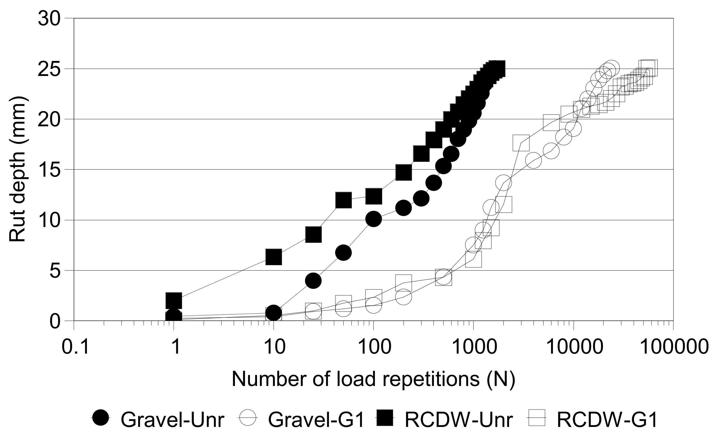
Figure 4 shows the results of tests on unreinforced roads, where the target surface rut depth of 25 mm at the fill surface was reached for close values of a number of load repetitions (N) for both fill materials (N equal to 1630 and 1710 for the gravel and RCDW roads, respectively). However, the presence of reinforcement (geogrid G1) made a significant difference on the road performance, as can be seen in
Figure 4. In this case, the 25 mm-deep rut was reached in the reference (gravel) road for a value of N of 24,064, whereas in the case of the reinforced RCDW road it was reached for a value of N of 57,235. It should be noted that up to a rut depth value of 22 mm (N ≅ 11,000) the behaviour of the two fill materials was very similar. As that rut value came closer to the target maximum rut depth, it may be considered that both materials behaved similarly under reinforced conditions, with a TBR (traffic benefit ratio = N
r/N
unr, where N
r and N
unr are the values of N under reinforced and unreinforced conditions, respectively, for a given rut depth) of the order of 15 at the end of the tests. Similar tests after road surface repair showed the good performance of the reinforced roads (gravel and RCDW fills) in terms of TBR values, particularly for tests with reinforcements less prone to suffering mechanical damage [
59].
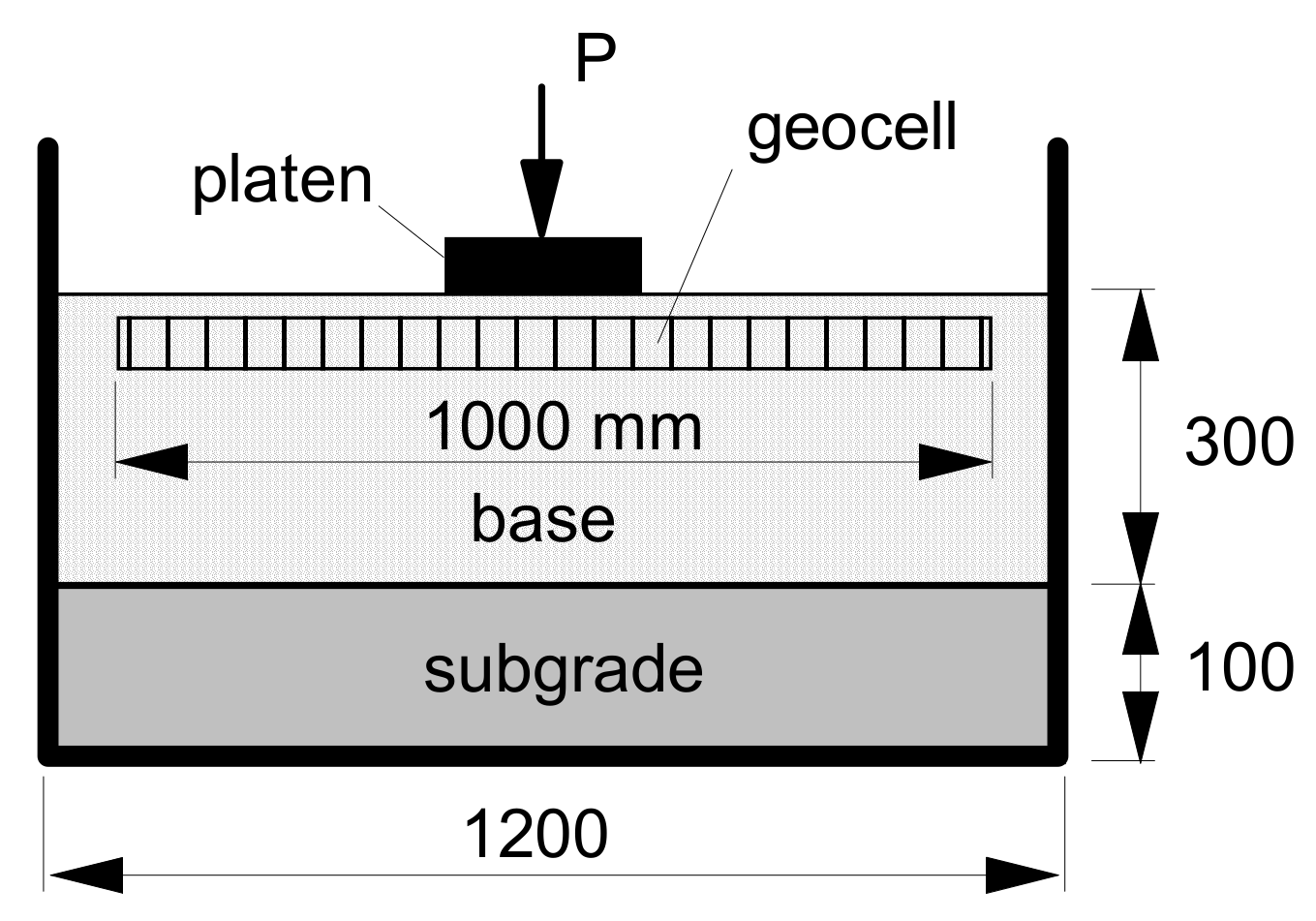
Mehrjardi et al. [
62] reported the use of construction and demolition wastes as fill materials combined with geocell reinforcement in unpaved roads on compressible subgrade.
Figure 5 shows a schematic of the test equipment used in the investigation. A natural aggregate (gravel, USCS classification = GP, D
50 = 4.6 mm, D
10 = 0.2 mm and coefficient of uniformity (CU) of 26.3) layer was also used as fill material for comparison purposes. The alternative base materials consisted of a waste soil (fine-grained fraction of the CDW, USCS classification = GW, D
50 = 1.3 mm, D
10 = 0.12 mm and coefficient of uniformity (CU) of 19) and a recycled concrete aggregate from CDW (USCS classification = GP, D
50 = 3.0 mm, D
10 = 0.21 mm and coefficient of uniformity (CU) of 18). The subgrade soil consisted of the wasted soil with a moisture content of 1.5% and a relative density of 60%. The geocells utilised were manufactured from a heat-bonded nonwoven geotextile made of polypropylene, with cells with equivalent diameter and height of 55 mm and 50 mm, respectively; a mass per unit area of 690 g/m
2; and a secant tensile stiffness at 5% strain of 5.7 kN/m.
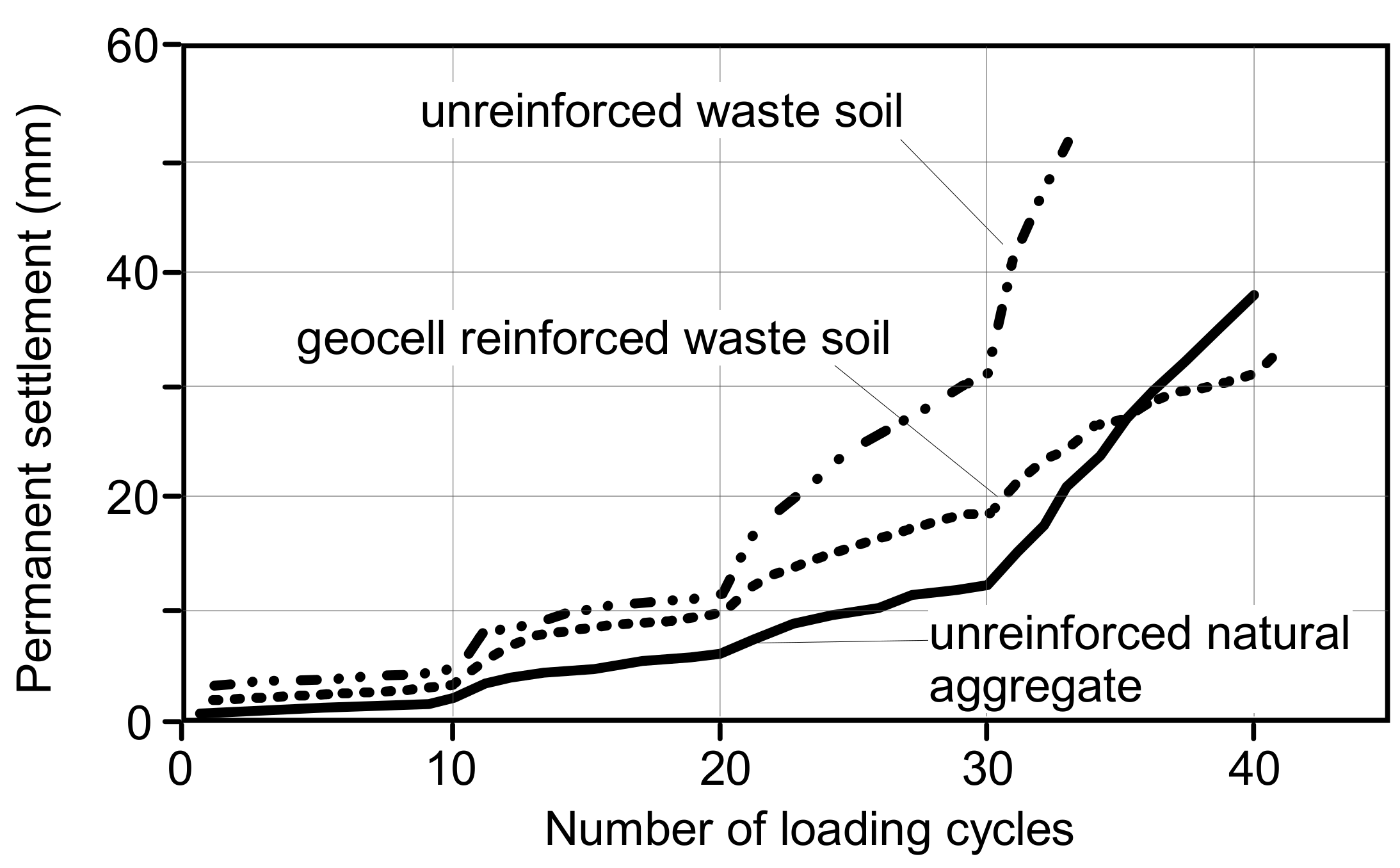
Figure 6 shows some test results obtained by Mehrjardi et al. [
62] in terms of permanent settlement at the fill surface versus number of load repetitions for the tests with the waste soil and natural aggregate. This figure shows that the geocell-reinforced road built with the waste soil performed significantly better than its unreinforced counterpart and presented similar performance to that of the natural aggregate at the end of the test.
The results presented in
Figure 4 and
Figure 6 show the potential of the use of recycled construction and demolition wastes reinforced with geosynthetics in unpaved roads on poor subgrades. The utilisation of RCDW will avoid or reduce the use and exploitation of more expensive natural materials, with favourable repercussions to the environment.
3.3. Recycled Construction and Demolition Wastes in Geosynthetic-Encased Granular Columns
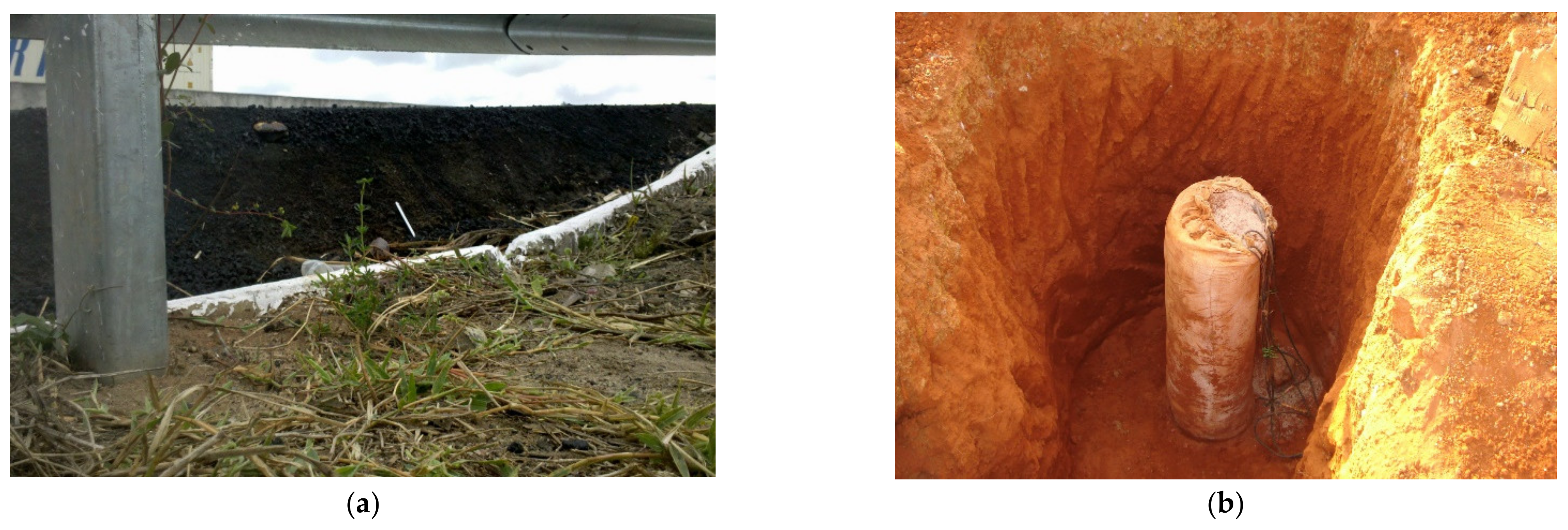
Alkhorshid [
63] investigated the use of geosynthetic-encased columns (GEC) to reduce excessive settlements and failure of embankments built on soft soils (
Figure 7a,b). In this type of subgrade, there is low confinement at the upper part of the granular column, reducing its load capacity. A technique that has been applied to increase column lateral confinement is the use of geotextile encasement (
Figure 7b). Large scale tests were carried out by Alkhorshid [
63] on conventional and geotextile-encased granular columns using a large box (1.6 m × 1.6 m × 1.2 m) to investigate the use of three types of woven geotextile encasements and three types of infill materials, including RCDW. The GEC models were 1000 mm in height and 150 mm in diameter. Sand, calcareous gravel, and recycled construction and RCDW were used as infill materials for the columns. Bentonite (4% in mass) was added to the subgrade soil to increase its plasticity and workability, resulting in a soft subgrade classified as CH by the Unified Soil Classification System (USCS). The properties of the soft soil and filling materials and the geotextile characteristics are presented in
Table 4 and
Table 5. If a scale factor of 4 is considered, the tests would simulate a prototype problem of a 0.6 m-diameter encased column in a soft clay with an undrained strength of 20 kPa. During the tests, monotonically increasing vertical loads were applied to the column top by a rigid steel plate.
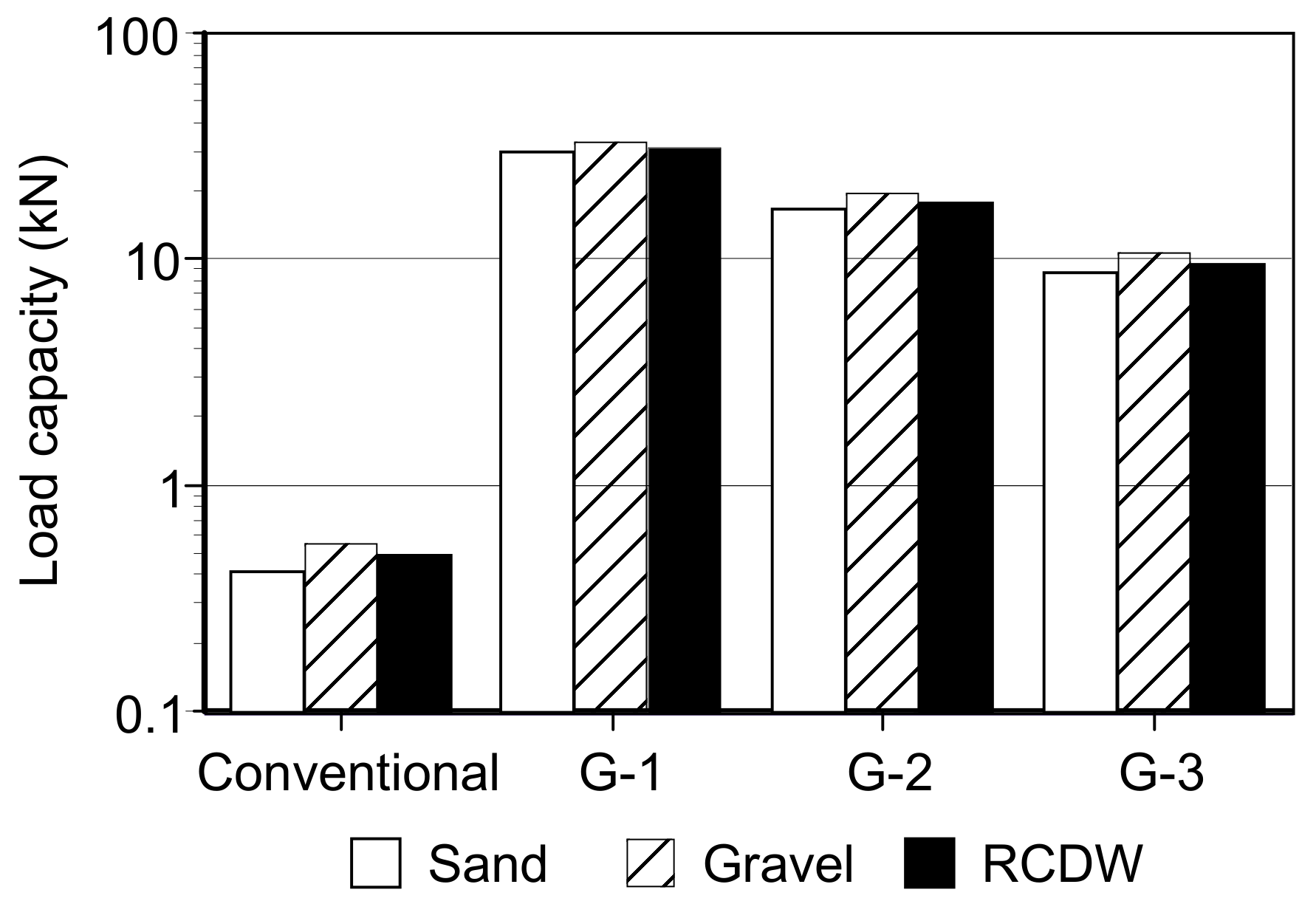
The G-1-encased column (the column using geotextile G-1,
Table 5, with the highest tensile strength and stiffness) presented higher bearing capacity and lower settlements than those encased with G-2 and G-3. Moreover, the maximum lateral bulging of the encased columns was observed for the column encased with the most extensible geotextile (G-3), at a depth ranging from 1 to 1.5 times the column diameter.
Figure 8 shows values of load capacities of the columns encased by geotextile G1 and with the three different infill materials tested (sand, gravel, and RCDW). This figure also shows the results for the conventional materials (no encasement). A significant increase in column load capacity was observed with the use of geotextile encasement. It is also noticeable that the values of load capacity of the RCDW-encased columns were very similar to those of the traditional natural infill materials, which highlights the potential use of RCDW as infill material in encased granular columns for the stabilisation of embankments on soft soils. Additional information on this type of application of RCDW can be found in Alkshorshid [
63] and Alkhorshid et al. [
63,
64,
65].
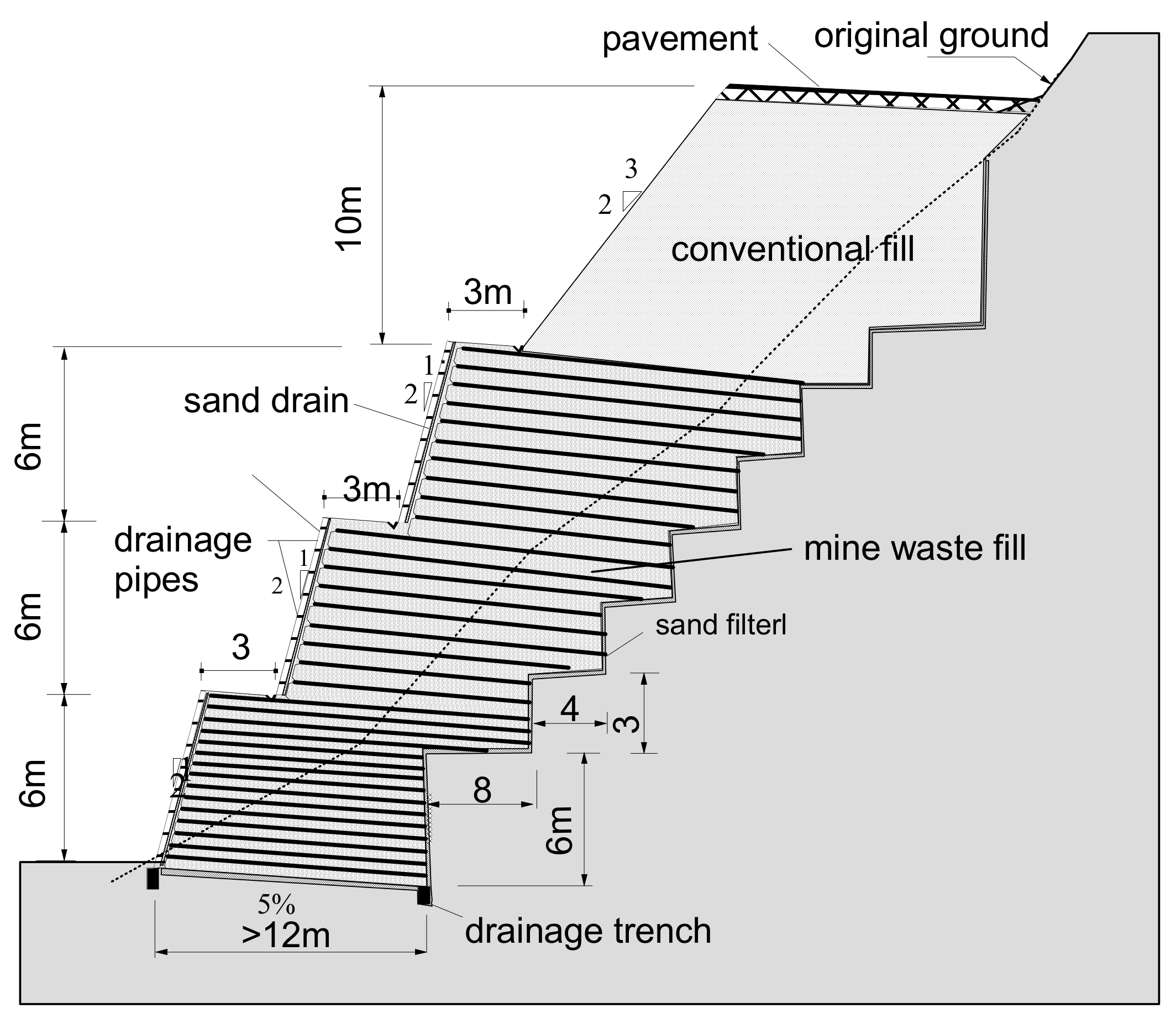
3.4. Reinforced Soil Structures Constructed with RCDW: Performance
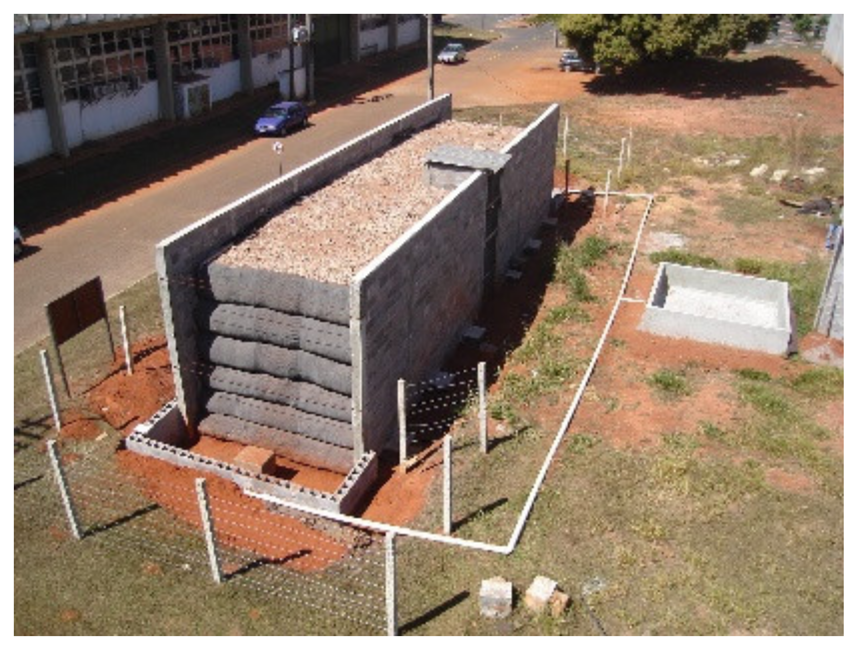
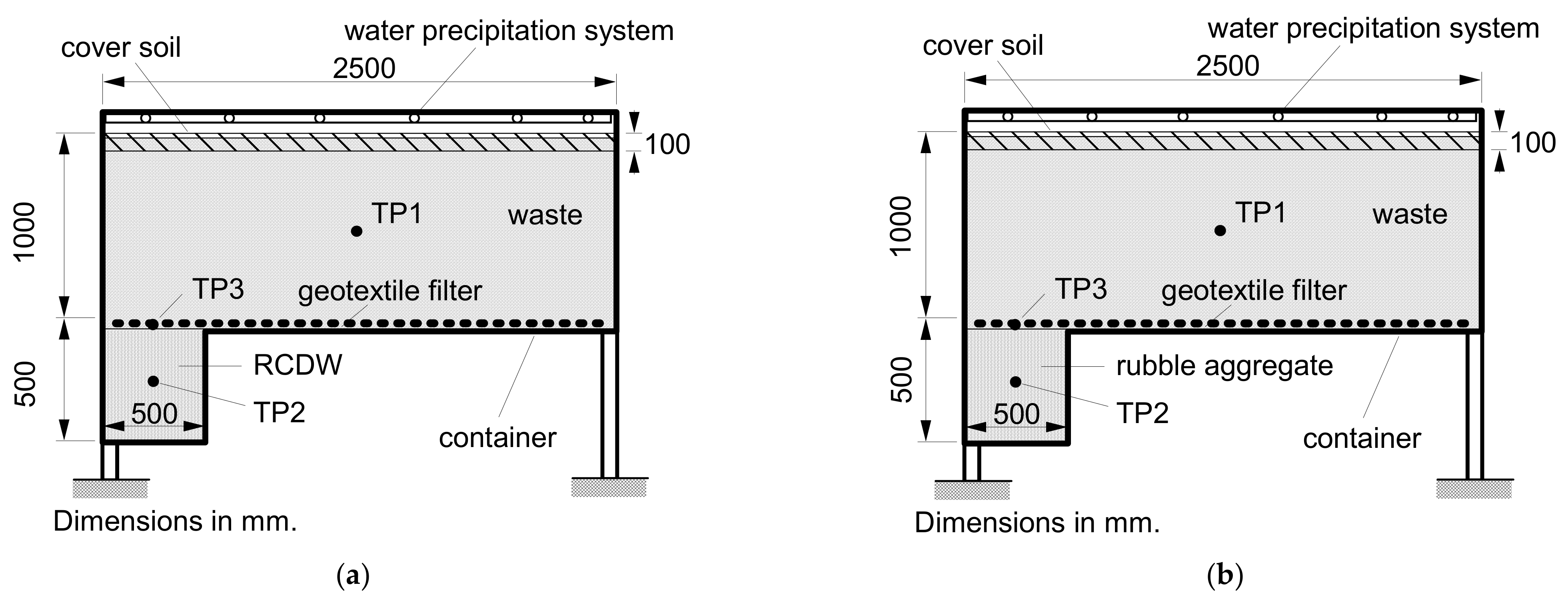
As part of a research programme on the combined use of CDW and geosynthetics in geotechnical and geoenvironmental works at the University of Brasília, Brasilia, Brazil, a research project was responsible for the conception, construction, instrumentation, and monitoring of two full-scale GRS structures using RCDW as backfill material. The 3.6 m-high wrapped face walls were constructed over a porous collapsible foundation soil located at the Foundation and Field Investigation Site of the Graduate Programme of Geotechnics of the University of Brasilia. Because the walls were monitored through dry and rainy seasons, it was possible to observe the influence of the properties and performance of the foundation soil on walls deformations, settlements, horizontal earth pressures, and reinforcement strains [
55,
66,
67]. The walls were constructed with different geosynthetic reinforcements (Wall 1: PET geogrid and Wall 2: PP non-woven geotextile) and back-to-back in a reinforced masonry block facility (
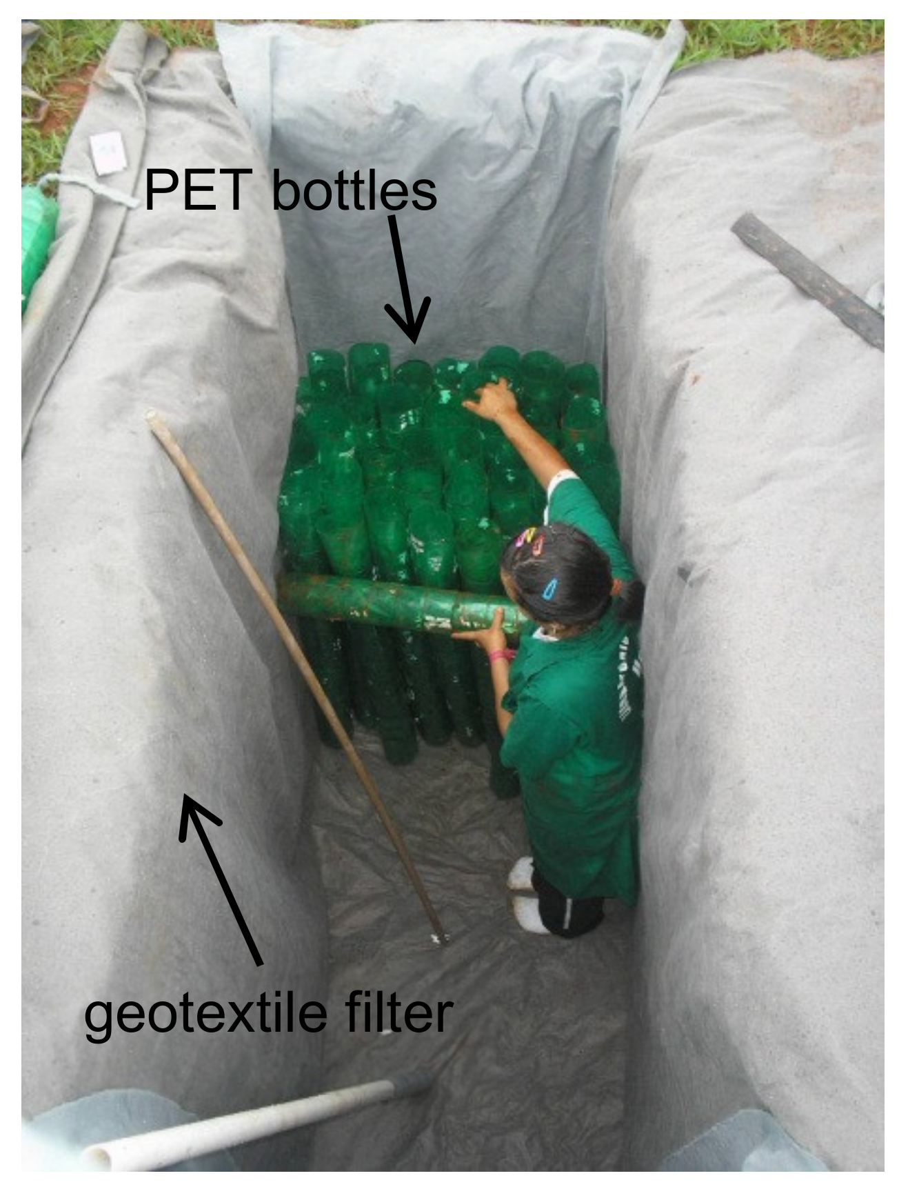
Figure 9). Three layers of lubricated polyethylene sheets were placed on the internal faces of the facility to minimise the influence of soil-side wall friction on the test results.
Table 6 and
Table 7 present the properties of RCDW and geosynthetics used in these experiments, respectively.
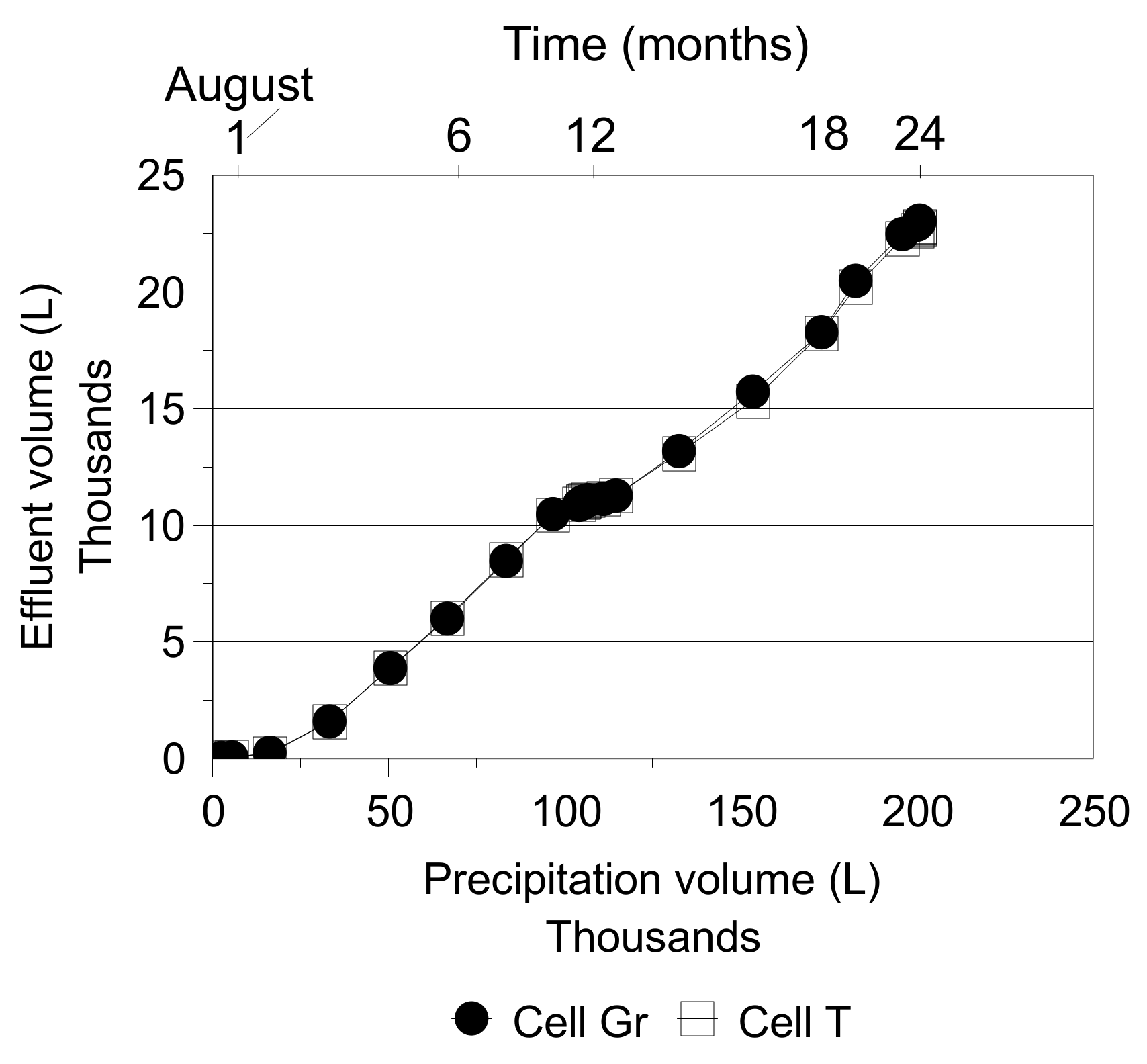
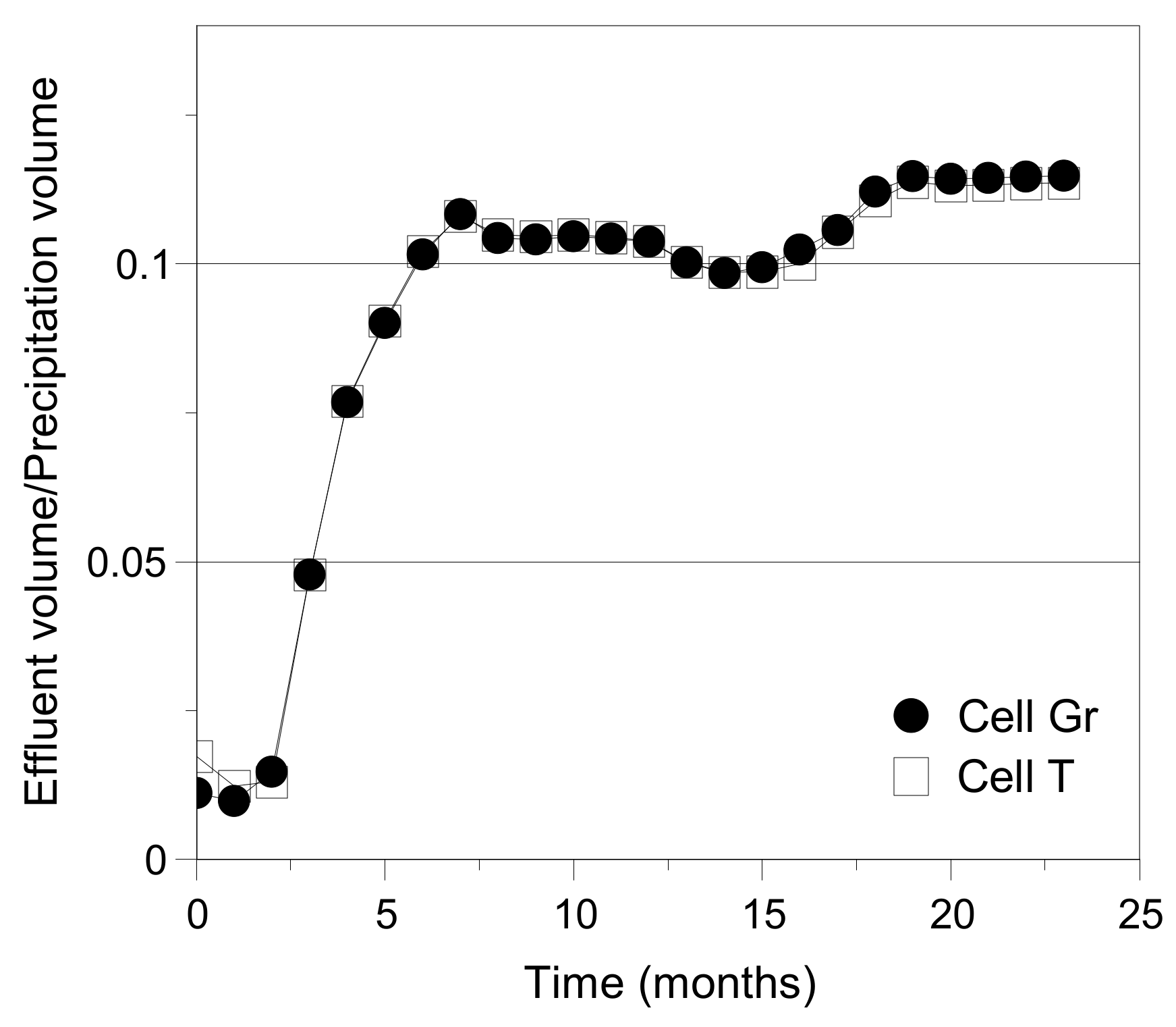
Besides the expected collapse of the foundation soil due to the natural infiltration of water through the wall face and backfill surface during the rainy season, artificial inundation was also carried out to enhance foundation soil collapse in a controlled manner and thus further investigate its effect on the performance of the walls. To assure the complete infiltration of water into the foundation soil, a granular drainage layer was installed at the base of the walls and water reservoirs were constructed adjacent to the test facility (
Figure 9).
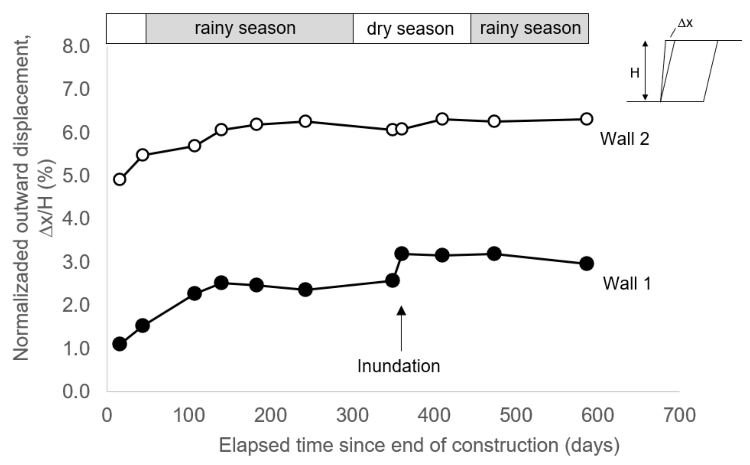
Because the walls were built during the dry season, the following rainy season presented a relevant effect on the performance of the walls, mainly during the first 100 days, which resulted in approximately 250 mm of cumulative precipitation. Concerning the horizontal displacements of the wall face, it was noted that after being subjected to the first rainy season or to artificial inundation (the latter for Wall 1) the values measured tended toward stabilisation. The artificial inundation of the foundation soil presented a greater influence on Wall 1 (geogrid) and were shown to be negligible for Wall 2 (nonwoven geotextile wall).
Figure 10 presents the normalised horizontal displacements measured (at a normalised elevation of 0.83) at the wall faces from the end of construction up to 587 days after construction. Measures of inward displacement at the crest of both walls were also observed, which may have been a consequence of the compressibility of the foundation soil at the wall toe as reported in other studies not related to the use of RCDW as backfill material [
68,
69,
70,
71]. Although both walls showed the largest outward displacement at an elevation equal to 3.00 m (h/H = 0.83, where h is the elevation and H is the height of the wall), the final values for Wall 2 (Δx/H = 6%, where Δx is the face horizontal displacement) were about twice those of Wall 1 (Δx/H = 3%). This performance of Wall 2 can be explained by the fact that nonwoven geotextile presents much lower stiffness under the unconfined conditions at and closer to the wall face, where the occurrence of greater reinforcement bulging was marked. The maximum outward post construction movement observed was greater than the values recorded for conventional wrapped-face walls in a database of wall case studies collected by Bathurst et al. [
72]. Clearly, the performance of the walls can be attributed to the compressibility of the foundation soil. However, the magnitudes of face displacements recorded by Santos et al. [
67] could be acceptable for temporary structures in some jurisdictions (e.g., WSDOT [
73]) or even prevented by means of some foundation soil treatment, which could be carried out before or simultaneously to the wall construction.
The displacement of the wall top was influenced by the first rainy season (following the construction of the walls) in a very significant manner, associated with a value of 250 mm of cumulative precipitation as a trigger to the process. Differences in settlement profiles were observed, which can be attributed to differences in the compressibility of the foundation soil under each wall. The wall crest presented the most significant vertical displacements for both walls, with the highest values observed for Wall 1 (
Figure 11). Considering the wall top, for x/B = 0.24, where x is the distance from the wall face and B is the wall base width, the stabilisation of displacements was observed at 261 days after construction, which was associated with approximately 1250 mm of cumulative precipitation. However, the artificial inundation showed that this stabilisation was due to the reduction in precipitation and infiltration of water, because of the dry season’s proximity. In a period of just 48 h after the artificial inundation process, the vertical displacement at x/B = 0.24 increased by 45% and 39% for Walls 1 (geogrid) and 2 (nonwoven geotextile), respectively. The effects caused by the artificial inundation continued for approximately 48 days (during the dry season), with increments of 8% and 15% for Walls 1 and 2, respectively. The second rainy season showed no significant influence on the vertical displacements at the wall top up to the end of monitoring of the walls (587 days after the end of construction).
Concerning the reinforcement strain, much higher values were observed close to the face of Wall 2 (nonwoven geotextile) compared to Wall 1, particularly for reinforcement layer 5 (elevation of 2.4 m). Maximum strains in this layer in Wall 1 reached 0.23% just before the artificial inundation of the foundation, whereas for the same reinforcement layer in Wall 2 the maximum strain was equal to 12.4%. The maximum reinforcement strains in Wall 1 reveal the viability of using RCDW as backfill material once such values are consistent with the low strain levels reported in databases of monitored geosynthetic soil walls under operational conditions by Miyata and Bathurst [
74] and Bathurst et al. [
75]. The larger values of strains close to the face of Wall 2 (nonwoven geotextile) are a consequence of the low confinement in that region. Beyond half of the base length, the RCDW provided enough confinement to the geotextile reinforcement and the strains were low (below 1%) in both walls. The effects of the rainy season on reinforcement strains were noted more significantly in Wall 1, with the cumulative precipitation of 250 mm working again as a trigger. On the other hand, the results indicate that reinforcement strain mobilisation in Wall 2 occurred during the construction process, with the rainy season and artificial inundation not causing relevant changes.


