Review

Smart Integration of Electric Buses in Cities: A Technological Review

1
MOBI Research Group, ETEC Department, Vrije Universiteit Brussel (VUB), Pleinlaan 2, 1050 Brussel, Belgium
2
Flanders Make, Gaston Geenslaan 8, 3001 Heverlee, Belgium
*
Author to whom correspondence should be addressed.
Sustainability 2021, 13(21), 12189; https://doi.org/10.3390/su132112189
Submission received: 30 September 2021 / Revised: 29 October 2021 / Accepted: 1 November 2021 / Published: 4 November 2021

Abstract

:
This paper provides a comprehensive overview of the state-of-the-art related to the implementation of battery electric buses (BEBs) in cities. In recent years, bus operators have started focusing on the electrification of their fleet to reduce the air pollutants in cities, which has led to a growing interest from the scientific community. This paper presents an analysis of the BEB powertrain topology and the charging technology of BEBs, with a particular emphasis on the power electronics systems. Moreover, the different key technical requirements to facilitate the operation of BEBs are addressed. Accordingly, an in-depth review on vehicle scheduling, charger location optimization and charging management strategies is carried out. The main findings concerning these research fields are summarized and discussed. Furthermore, potential challenges and required further developments are determined. Based on this analysis, it can be concluded that an accurate energy consumption assessment of their BEBs is a must for bus operators, that real-time, multi-objective smart charging management strategies with V2X features should be included when performing large bus fleet scheduling and that synchronized opportunity charging, smart green depot charging, and electric bus rapid transit can further reduce the impact on the grid. This review paper should help to enable a smarter and more efficient integration of BEBs in cities in the future.

1. Introduction

Climate change and air pollution are two major environmental concerns worldwide, and both are directly linked to emissions caused by human activities. The largest source of greenhouse gas (GHG) emissions, which contribute to global warming, and air pollutants, which affect human health, is the combustion of fossil fuels. This results in the production of excessive amounts of carbon dioxide (CO2), nitrogen oxides (NOx), particle matter (PM10 and PM2.5) and carbon monoxide (CO). In the EU, the transport sector considerably contributes to GHG emissions and air pollution. In particular, road transport accounts for almost 20% of total CO2 emissions, 39% of NOx emissions, 11% of PM2.5 and 20% of the CO emissions [1,2]. Especially, urban areas are exposed to these pollutants due to dense traffic. By means of diesel buses, public transportation is one of the main air polluters in and around cities. Hence, cleaner alternative solutions have been investigated and analyzed by researchers [3,4]. Accordingly, battery electric buses (BEBs) are recommended as the best option to improve air quality and counteract climate change because of the absence of tailpipe emissions. Furthermore, BEBs also produce less noise and vibrations, which contributes to a more comfortable trip for passengers.
In recent years, the number of electric buses in Europe has strongly increased, and public transport operators (PTOs) are introducing BEBs into their fleet [5,6]. However, several financial, organizational and technological barriers still exist that need to be addressed before the widespread adoption of BEBs [7]. Financially, the high up-front capital cost of BEBs is one of the main hurdles. However, it has been reported that by 2030 at the latest, cost parity with diesel buses will be reached, because by then battery prices will have significantly reduced [8]. Organizationally, finding the space to install the charging infrastructure and a plan to replace the current bus stock is necessary, as is the consideration of long-term implications. Technically, the major challenges are related to the charging infrastructure and the battery capacity. BEBs have a limited driving range compared with diesel buses and require dedicated high-power supply systems to support the charging demands. To overcome the driving range limitation, bus operators need to investigate which vehicle types and charging technology are suited for the specific needs of the different bus routes in their city. Furthermore, the large-scale deployment of BEBs in cities will substantially negatively impact the electrical grid, creating component overloading, harmonic pollution, power loss, and voltage and stability issues [9,10]. To mitigate them, the charging of BEBs needs to be properly managed, and the infrastructure needs to be adjusted.
In scientific literature, these topics have recently gained a lot of interest, and many of the challenges have been addressed. Still, and especially on a technological level, several advancements can be made to smoothen the integration of BEBs in cities. The present study therefore intends to tackle the technical aspects associated with the integration of BEBs in cities by providing an overall picture of the existing charging technology and fleet management techniques and identifying the key elements for a smarter integration and future research in this domain. The remainder of this study is organized as follows. Section 2 describes the BEB powertrain topology. In Section 3, the different charging concepts, including the power electronic (PE) system topologies for BEB charging infrastructure, is presented. Section 4 provides a comprehensive review of the recently published studies on vehicle scheduling, charger location optimization and charging management for BEB fleets, whereas Section 5 discusses the advantages and disadvantages of the presented research and proposes future research recommendations and opportunities. Finally, the concluding remarks are provided in Section 6.

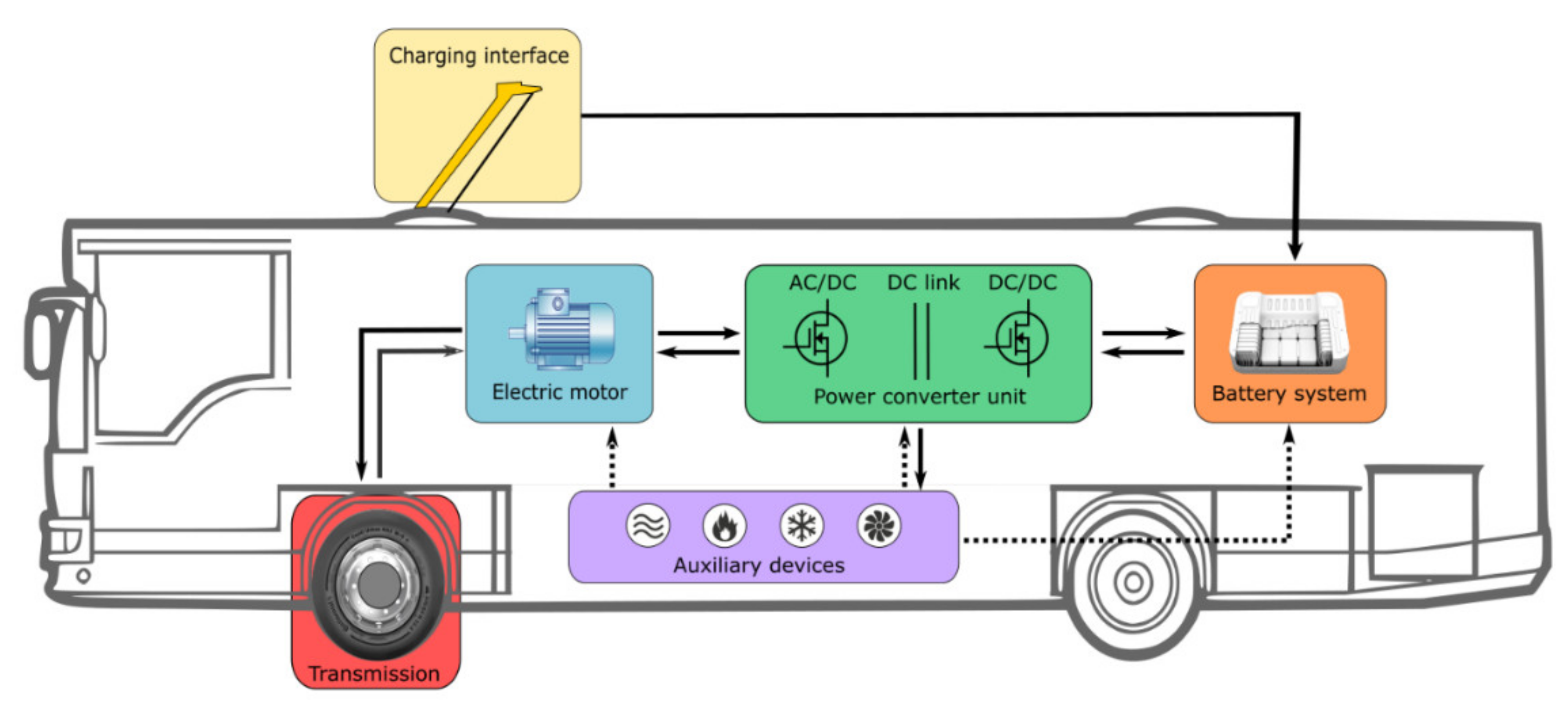
2. Battery Electric Bus Powertrain Topology
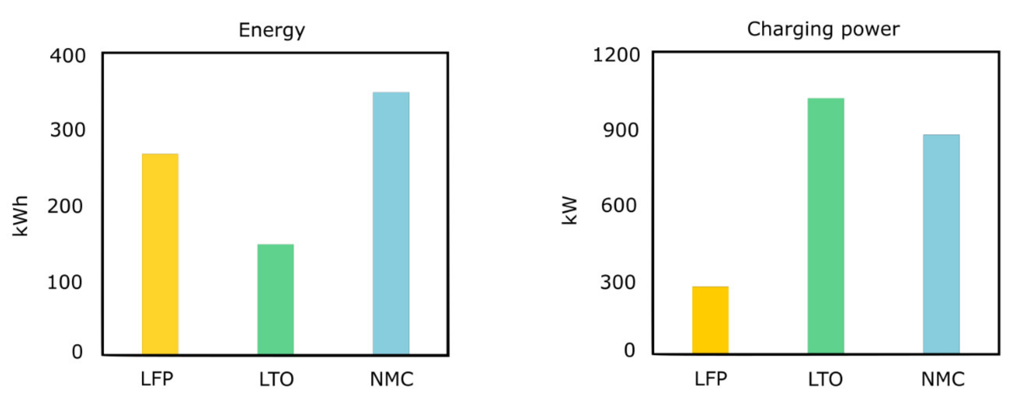
As shown in Figure 1, the powertrain of a BEB is equipped with a battery system and an electric motor (EM). In between, a power electronic converter (PEC) is required to regulate the power flow from the battery system to the EM and vice versa (in the case of regenerative braking). A transmission system sends the energy to the wheels to drive the BEB. While braking, the regenerative braking energy can be recuperated to charge the battery. Another way to charge the battery is to use the charging interface and charge it with electricity from the grid. Furthermore, the battery power is also used to cover the power needs of the auxiliary devices, which is necessary to cool down the other powertrain components and heat the cabin of the BEB [4,11].

2.1. Battery System

The battery system is the main and only energy source on board. This means that all the required energy for driving the bus originates from the battery and that the battery energy capacity determines the driving range of the BEB. As in all electric vehicles nowadays, BEBs are equipped with some form of lithium-ion batteries. Currently, lithium iron phosphate (LFP), lithium titanium oxide (LTO) and lithium nickel manganese cobalt oxide (NMC) are the conventional battery types encountered in BEBs [6,12]. Figure 2 shows a comparison of the energy and charging power of these different battery types in a conventional city BEB. LTO has the highest charging power of the considered technologies, but it also has the lowest energy capacity. Therefore, LTO is only applicable for charging on-route charging (see Section 3). On the other hand, LFP only accepts a very low charging power and can therefore only be used for slow charging situations, like charging in the depot. Finally, NMC has the largest energy capacity, as well as a high charging power and is therefore suitable for both on-route and depot charging [13].

2.2. Electric Motor

The EM converts the electrical energy coming from the battery to mechanical energy to drive the wheels. It can also operate as a generator to send the regenerative braking energy back into the battery system. The majority of BEBs use AC motors, in particular induction (or asynchronous) motors (IMs) and permanent magnet synchronous motors (PMSMs) [6]. IMs are preferred because of their reliability, robustness, mature technology, and low price, while PMSMs have a higher power density, higher efficiency, and a simple structure [14].

2.3. Power Electronic Converter Unit

A PEC unit is required to convert the DC power output of the battery system to AC input power for the EM. It mostly consists of two stages: a DC-to-DC conversion stage to connect the battery system to a high-voltage DC link, to which all the auxiliary devices are connected, and a DC-to-AC conversion (inverter) stage to connect the DC link with the EM. The inverter controls the EM speed by adjusting the AC voltage and the frequency. These converters are essential for a reliable and efficient BEB powertrain operation [15].

2.4. Auxiliary Devices

Besides the main drivetrain components of a BEB, there are also many essential auxiliary devices on board that require power from the battery system. The heating, ventilation and air conditioning (HVAC) system ensures the comfort of the passengers. The thermal management systems of the battery, the PEC unit and the EM enable a satisfactory and safe operation of these components. Other remaining electric auxiliaries ensure the operation of the doors, lights, wipers, etc. [16].

2.5. Energy Consumption

A well designed and optimized powertrain is essential for a reliable BEB operation. This mainly comes down to rightsizing the battery system to achieve a desirable driving range. Furthermore, since the battery is still the most expensive component of the drivetrain, an optimized battery system will also have a positive influence on the overall cost of the BEB. For bus operators, a detailed knowledge of the energy consumption of the BEB under different operating conditions, such as weather conditions, driving cycles and passenger occupancy, is required. This information helps with the intelligent integration of BEBs in cities by helping bus operators to identify which bus types can be used on which lines. Several researchers have investigated the performance and energy demand of BEBs and have found that the average energy consumption lies between 1–2 kWh/km, 1.5–3 kWh/km and 2–3.5 kWh/km for standard buses, double-decker and articulated buses, respectively [17,18,19]. In heavy traffic and extreme weather conditions, BEBs generally consume more energy. The energy consumption of the propulsion system can increase up to 35%, and the auxiliary’s energy consumption could triple in peak traffic when compared to standard traffic. In extreme weather conditions, the total energy consumption of the BEB could even double, mainly due to the HVAC system [16,20]. These things should be considered when deciding on the battery size of BEBs. Still, since such extreme weather conditions do not occur very frequently, their probability of occurrence needs to be properly analyzed. Otherwise, this can lead to an oversized battery system.

2.6. Charging Interface

The on-board battery of BEBs needs to be charged regularly. Therefore, a BEB is equipped with a charging interface that can be connected to the appropriate charging infrastructure to charge the battery with power from the electricity grid. Different charging interfaces exist, as depicted in Figure 3.
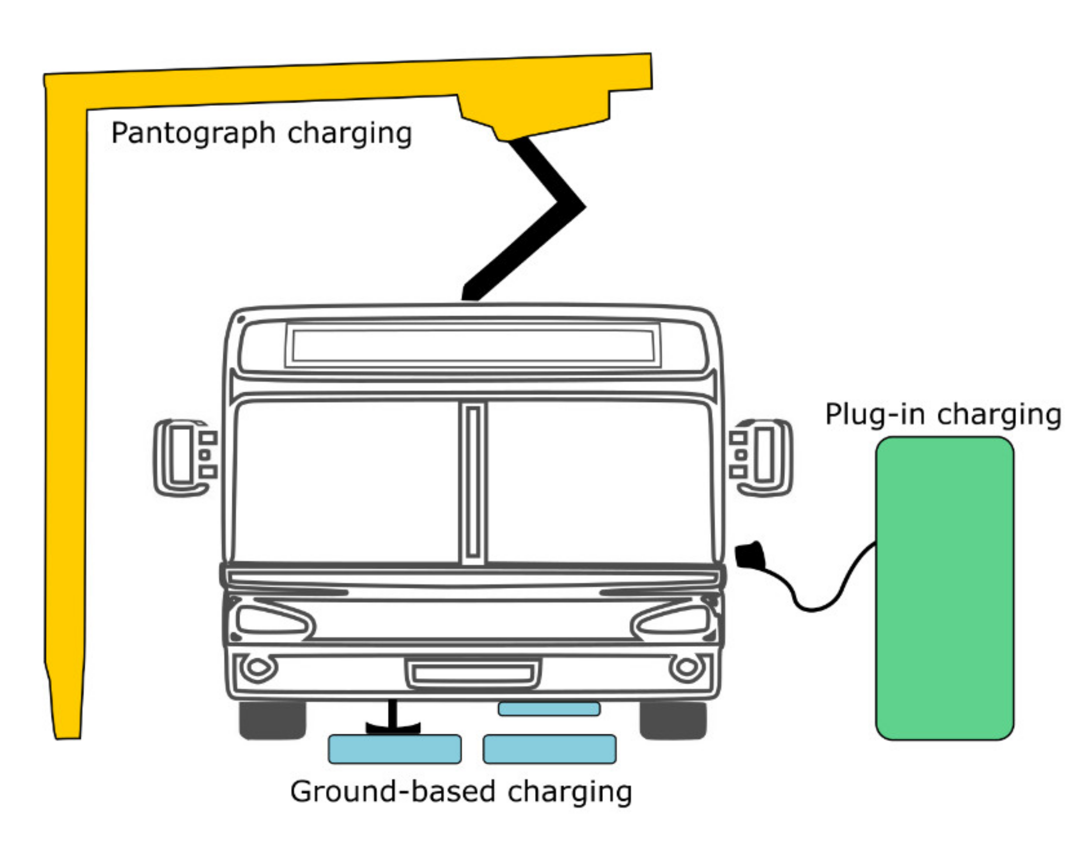
  • Pantograph charging: A common way to charge BEBs is by using a pantograph that makes contact between the bus and the charging infrastructure in an automated way. Currently, there are two ways to perform this contact. The pantograph can be mounted on top of the roof of the BEB (see Figure 1) and is lifted when charging is required, or the pantograph is mounted on the charging infrastructure and moves downwards (see Figure 3). The latter is preferable because it requires less pantographs for a given bus route and adds less weight to the BEB. Furthermore, the pantograph is not exposed to vibrations from the bus [21].
  • Plug-in charging: BEBs also can get charged by plugging in a connector from the charging infrastructure. Currently, the connector still needs to be plugged in manually, which makes this type of charging interface less attractive for larger BEB fleets. However, this process will also become automated through robotization in the near future [22].
  • Ground-based charging: In some cases, BEBs are getting charged through a ground-based charging system. This can be realized in two ways. Like pantograph charging, a current collector can be dropped down from the bus to contact a conductive device embedded in the road surface [23]. Another way is to transfer the charging power wirelessly by applying an electromagnetic field between a transmitting coil on the road surface and a receiving coil positioned on the BEB. The main advantage of wireless charging is that it can enable BEBs to charge while in motion [24,25].

3. Charging Technology

The charging infrastructure has a key role in the implementation of BEBs in cities. BEBs only use off-board chargers, whereas the PEC to convert the three-phase AC power from the grid into DC power to charge the battery is located outside the BEB. These chargers allow higher charging power levels because they are not restricted in size and weight. Furthermore, since the driving range of a BEB is limited, a specific charging concept is required to keep the BEB running during the day. This section gives an overview of the existing charging concepts and charger and PEC topologies to provide a reliable and efficient charging behavior.

3.1. Charging Concepts

The three most promising charging concepts are depot charging, opportunity charging and dynamic wireless charging. Each of them serves different needs, depending on the characteristics and requirements of the bus network in cities, and each has its advantages and disadvantages. With depot charging, as the name suggests, the BEBs are only charged inside the depot. This mostly happens overnight (which is why this is often referred to as overnight charging), but because of the limited range of BEBs compared with their diesel counterpart, charging might also happen once during the daytime. This is illustrated in Figure 4a, which shows an example of the bus battery SoC throughout the day. On the other hand, opportunity charging refers to charging on-route, at end terminals or at regular bus stops. As such, the BEB is regularly charged during the day, without having to get fully charged each time, as highlighted by the evolution of the SoC throughout the day in Figure 4b. Dynamic wireless charging is in fact a special case of on-route charging, where the BEB gets charged while it is driving on specific road sections that are equipped with inductive charging pads. The daily SoC evolution dynamic wireless charging resembles opportunity charging (see Figure 4b).
Typically, BEBs using depot charging have a large battery pack to ensure that they can be operated during a considerable portion of the day without having to return to the depot. The downside is that a larger battery increases the weight of the bus and requires more space, meaning that there is less space for passengers. Therefore, bus routes with a very high vehicle demand during peak hours need to employ depot charging outside of peak hours and use their large battery size to cover the entirety of the peak-hour duration [26]. The charging power is often not higher than 150 kW (slow charging for BEBs) since there is enough time to charge the BEBs fully. For opportunity charging, it is the other way around, the size and weight of the battery can be reduced, which is why this type of charging is preferred for articulated (18 m) buses. The charging power can go up to 600 kW to sufficiently charge the BEBs in 5–10 min. As a result, opportunity charging at end terminals is often preferred by bus operators because at regular bus stops there is often no time to charge. In such a case, the charging power should be increased even more, which will result in very expensive chargers. For dynamic wireless charging, the size of the battery can be reduced even more, depending on how many inductive pads are installed under the road surface [27]. The charging power can also be reduced if the dedicated road sections are long enough. Still, this charging concept is very expensive to build, since the roads need to be completely reconstructed.
Currently, depot charging has the highest market share, although several studies [28,29] show that opportunity charging has lower lifecycle costs. However, with the decreasing battery cost, depot charging could reach a similar, or even lower, lifecycle cost. Another reason why bus operators might prefer this depot charging is that the charging infrastructure can be installed on their own property and can be centralized in one place. Furthermore, all types of BEBs can be charged here, no matter what their charging interface, although there is an increased interest in pantograph charging because of its potential to be automated. For opportunity charging, only pantograph or ground-based charging can be used. Either way, it is expected in the future that a mixture of both charging concepts will prevail because of the high diversity of bus routes in cities around the world. Dynamic wireless charging, on the other hand, is currently not yet implemented for BEBs and will presumably only be applied for bus-only lanes in the future. Table 1 gives an overview of the different commercially available chargers for BEBs.

3.2. Charging Infrastructure Topology

An off-board charger generally consists of a transformer, a harmonic filter and a PEC with a control and communication unit. The transformer provides galvanic isolation between the BEB and the grid. The filter is used to eliminate unwanted harmonic currents. The PEC converts the three-phase AC power from the grid into DC power used for charging the battery of the BEB. The control unit operates the switches of the PEC to adjust the voltage and current level to what the BEB can accept. The communication between the BEB and the charger is done based on the standard ISO 15118.
To ensure a safe operation of the charger, since it is characterized by high voltages and currents, galvanic isolation between the electrical grid and the BEB is required. This can be realized by two transformer topologies, as shown in Figure 5: a low frequency transformer (LFT) or a high-frequency transformer (HFT).
Figure 5a depicts a BEB charging station with an LFT between the electrical grid and the actual charger. Hence, the LFT is used to supply three-phase power to the charger. This bulky line frequency transformer increases the size and weight of the charger and complicates the installation. In addition, prominent conductors and bulky protection devices are required to deal with the high power. To overcome these issues, the operating frequency can be increased, which is realized through an isolated DC/DC converter, as depicted in Figure 5b [41]. The first stage consists of an AC/DC rectifier with a high voltage DC link. The second stage contains the HFT in the form of a solid-state transformer (SST) or power electronic transformer. In some cases, the HFT can also be part of the first power converter stage to create a low voltage DC link between the first and the second stage. A design with three stages with both a high-level and a low voltage DC link, and the HFT in between can also be considered [42].
Currently, the available charging infrastructure on the market uses LFTs, because they are more reliable than STTs. Furthermore, they are more efficient, less costly, and compatible with the protection that is used in the grid today. Nevertheless, STTs remain a promising alternative because apart from their size and weight reduction, they also enable full control of the voltage and the current, and hence allow power quality improvement [43,44]. Therefore, the design of STTs has been frequently addressed in the scientific literature. An overview of the state-of-the-art is provided in [45,46].
Because of the high power that is required for charging BEBs, especially for opportunity charging, often multiple identical PECs that are connected in parallel to a DC bus are integrated in the charging infrastructure, as illustrated in Figure 6 in the case of a LFT, and Figure 7 in case of an HFT. Such a modular approach increases the efficiency, the reliability and the flexibility of the system [47]. In this way, BEBs that accept a different charging power level can use the same charging infrastructure by up- or downscaling the power level through the operation of a different number of PECs. Furthermore, the presence of the DC bus allows the integration of energy storage systems (ESS) and renewable energy resources (RES) [48]. In depots, the modular approach can also be extended by integrating all the PECs in one charging cabinet from where multiple charging points are controlled. The charging points can then be installed at a certain distance from the charging cabinet, thus increasing the flexibility in terms of the configuration.

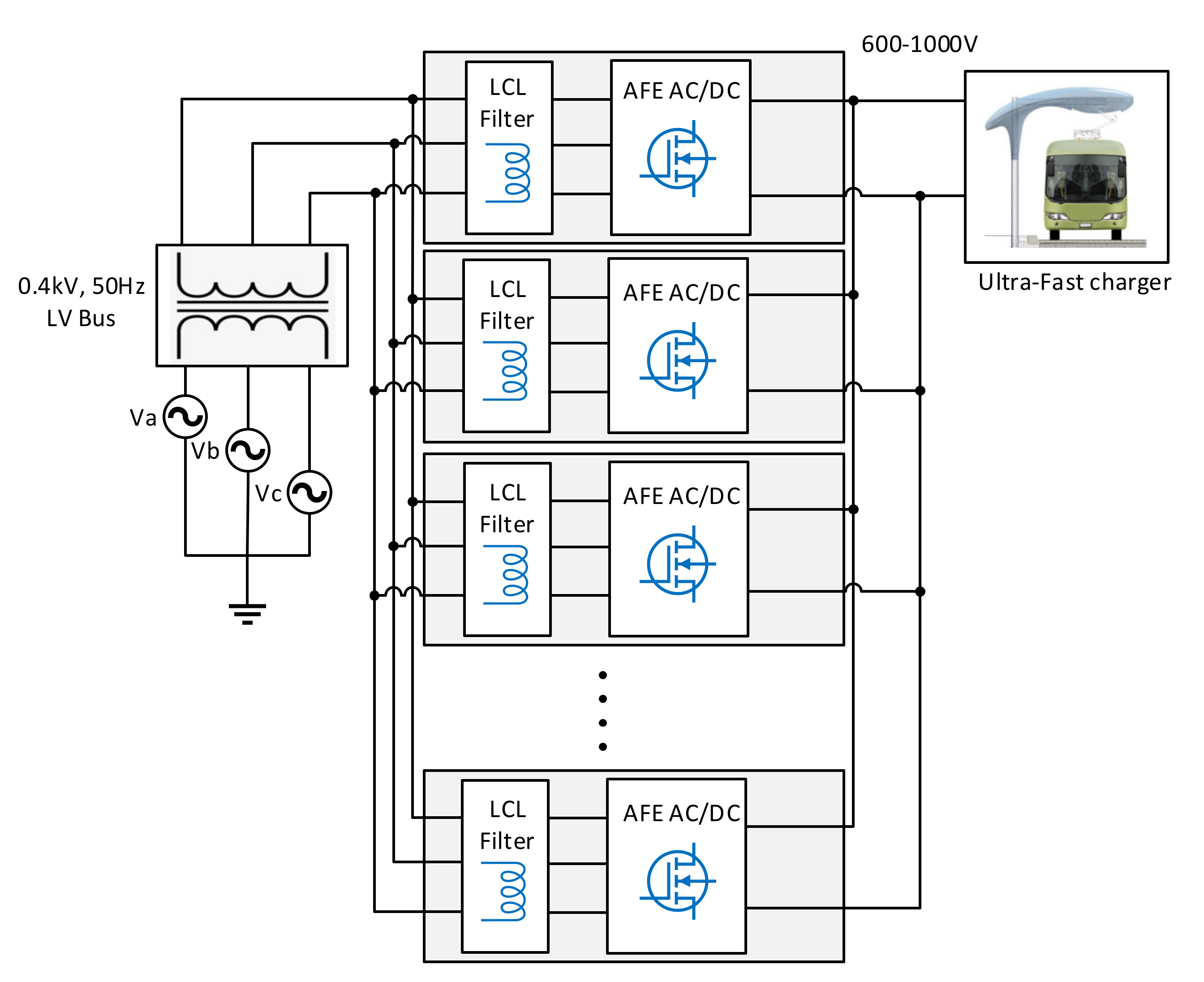
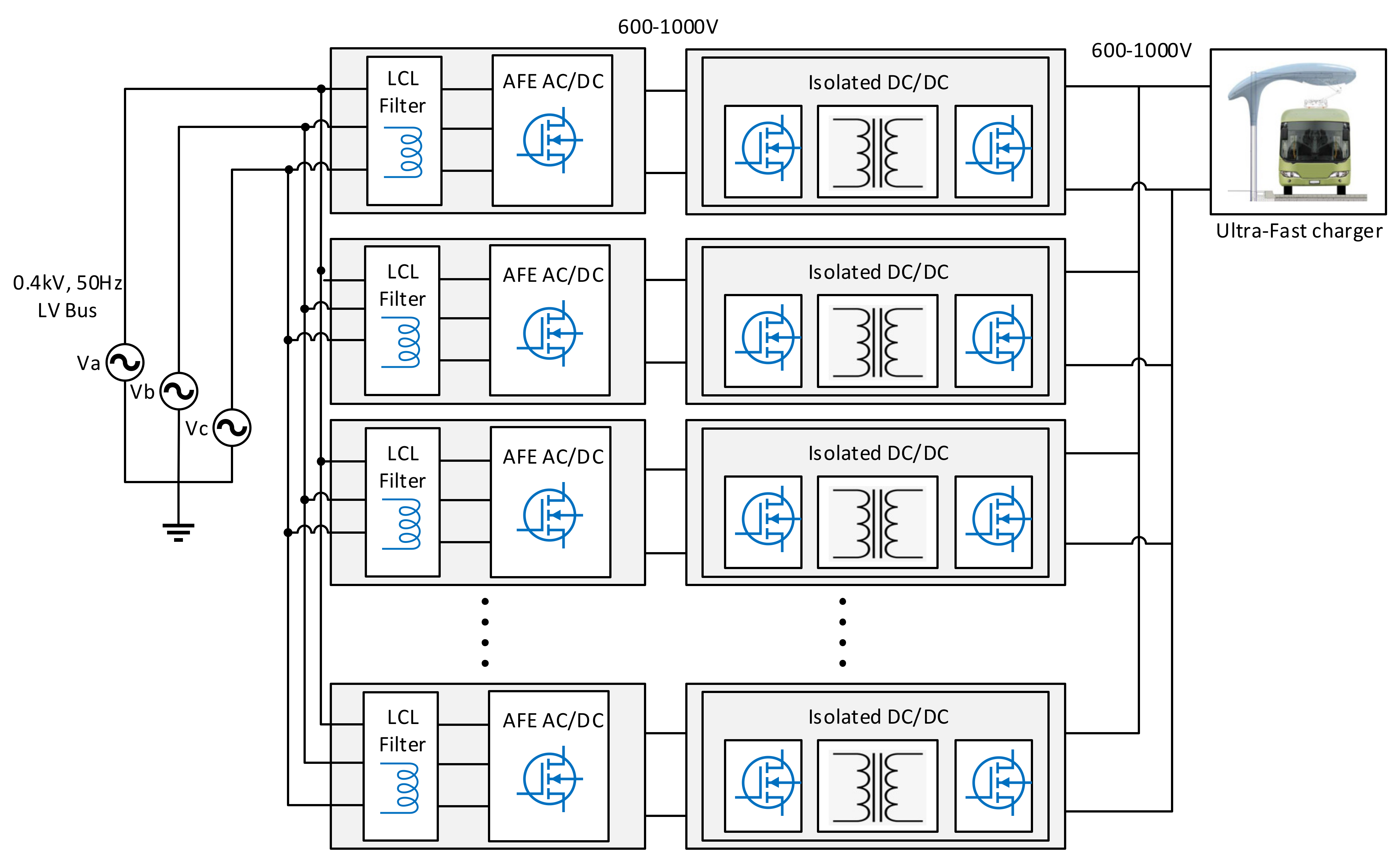
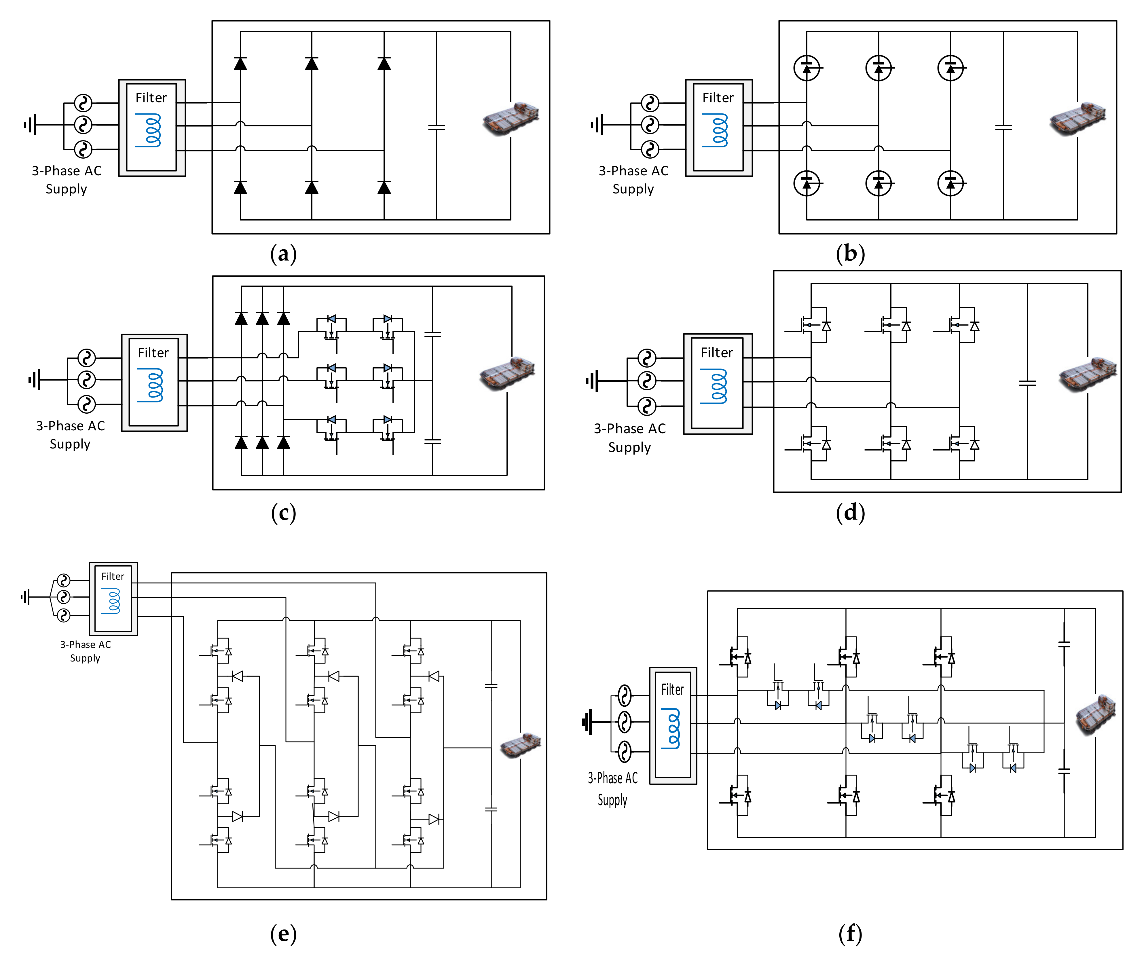
3.3. Power Electronic Converter Topology
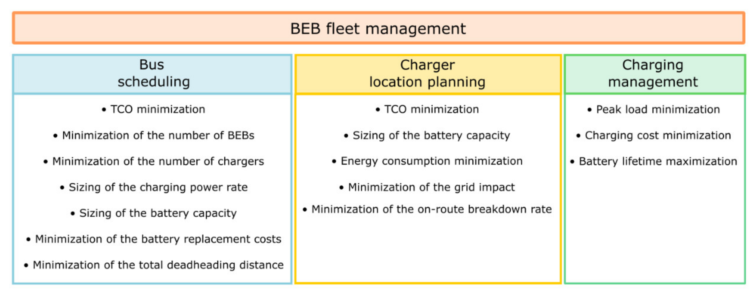
The most essential components of a PEC are the switches. At charging stations, the switches of the PEC convert AC power into DC power, allowing BEBs to connect and charge their batteries. The AC/DC conversion stage can be realized through an active front-end (AFE) converter. Several topologies exist to establish a three-phase AFE AC/DC PEC. It can include a diode bridge rectifier, a thyristor bridge rectifier, a Vienna rectifier, an active two-level buck/boost rectifier, or an active three-level rectifier as shown in Figure 8 [41,49,50]. The simplest and most cost-effective approach for the AC/DC conversion is a diode rectifier. However, the fixed output voltage depends heavily on the three-phase supply voltage and it induces an unfavorable total harmonic distortion (THD). Implementing a Vienna rectifier can enhance the THD of the line current, but it has a limited reactive power control. These topologies, however, only allow a unidirectional power flow and can therefore not be used for vehicle-to-grid (V2G) applications. For a bidirectional power flow, a two- or three-level rectifier should be used. The two-level rectifier is widely used because it has a simple structure, it is easy to control through PWM and it generates low-harmonic currents. A three-level converter delivers even better performance in terms of system harmonics, but it also has an increased number of switches, resulting in an increased cost, size, and weight. Among all the described three-phase AC/DC conversion topologies, the two-level AFE boost rectifier, as shown in Figure 8d, is the best option for a charger of BEBs, since from the design point of view, it is necessary to attain a high efficiency, a high-power factor, a cost-effective system with a reduced size and weight, a distortion-free operation with a limited grid impact and a high reliability.
Nowadays, the switches inside the PECs used in the charging infrastructure for BEBs are mainly based on silicon (Si) IGBT semiconductor technology. However, recent advancements in the switching technology have contributed to the development of wide bandgap (WBG) semiconductor materials such as Silicon Carbide (SiC) and Gallium Nitride (GaN). These new WBG semiconductors enable the development of PECs that are more compact and efficient, and that can operate at higher voltages, higher frequencies and higher temperatures, compared with Si-based semiconductors [51]. For high-power applications, such as BEB chargers, SiC-based switches will mainly be used because of their lower conduction voltage drop and their higher thermal conductivity, which leads to a significant reduction in the power losses [52].

4. Fleet Management

BEBs were first introduced in cities through pilot projects, where the optimal planning of the BEBs and the charging infrastructure was only considered for the specific bus route where the BEBs were operated. This approach could lead to an extremely oversized bus fleet and charging infrastructure network, since BEBs and charging infrastructure can potentially be employed and shared among multiple bus lines. Therefore, the adoption of BEB fleets requires rigorous scheduling on a vehicle and a charging level.
Managing an entire fleet of BEBs is a challenging upcoming task for bus operators. Since every city has a different climate and topography, and operational conditions, including traffic, bus schedules, available public transport modes, passenger profiles, and grid energy load profiles, the driving range of similar bus types will be different too, resulting in other choices of appropriate vehicle types, battery capacities and charging concepts between one city and another. This makes it clear that there exists no one-fits-all solution and that it is difficult to learn from the experiences of other cities.
In general, there are three main tasks that need to be considered when introducing a large BEB fleet into a city. One of these tasks is bus scheduling, also known as the electric vehicle scheduling problem (e-VSP). In theory, fleet electrification at minimal operational effort could be achieved by a one-by-one replacement, where each diesel bus is replaced by a BEB without having to change the operational planning. However, due to the limited range of BEBs, this will not be feasible in most cases; thus, charging during operation needs to be considered. This also implies that conflicts between BEBs at the charging infrastructure need to be avoided, which is particularly true for opportunity charging. Therefore, bus scheduling focuses on how to operate a bus fleet to fulfill a timetable of service trips with the aim to minimize the total cost of ownership (TCO), the total fleet size, the number of chargers, the deviations from existing bus timetables, etc., and to accordingly size the battery capacity of the BEBs and the charging power rate of the charging infrastructure.
Closely related to the bus scheduling problem is the location planning of the charging infrastructure. With a fleet of BEBs, it is important to have the charging infrastructure located at strategic places within the city where they can be used by multiple bus lines to minimize the TCO and where the distribution grid will not become overloaded.
Finally, it is also crucial to have a charging management when dealing with large bus fleets. BEBs require (very) high power for charging and currently charge as fast as possible from the moment they are connected to the appropriate infrastructure, even if there is plenty of time in the depot or at the terminal stop. This way of charging can be harmful for the distribution grid, as many BEBs will be charged at the same time, even when their location is optimized. As such, depot charging will create an unevenly distributed load profile and opportunity charging will induce high dynamic load peaks. Therefore, scheduling the charging process to shave the load peaks and flatten the demand curve is important for a smart integration of BEBs in cities. This reduces the need for expensive grid reinforcements, the need to invest in large ESS, and improves grid stability and reliability. Furthermore, with the higher penetration rate of renewable energy systems (RESs) such as photovoltaic (PV) systems and wind turbines, the charging process can be linked to the time-variable spot electricity price, instead of assigning a fixed price. This will allow us to perform charging in low-price periods and can reduce the charging costs. Another interest of charging scheduling is that battery ageing can be minimized and therefore the battery lifetime of the BEB can be extended.
Figure 9 provides an overview of the main tasks and the objectives for a proper fleet management of BEBs in cities. The following sections present a summary of the scientific research that has been carried out related to these topics.

4.1. Bus Scheduling

Early research on the BEB scheduling problem studied the simplest form of scheduling using a single depot with a single vehicle type [53,54,55]. These studies already give some insights into the important elements that should be considered when integrating BEBs in a bus fleet. More prominent results, however, are achieved when considering multiple vehicle types, multiple charging concepts, multiple depots, traffic, and weather conditions to include a variable energy consumption, as this gives a more realistic representation of the situation in cities. Moreover, the shift towards a full BEB fleet will happen gradually. Therefore, Rinaldi et al. [56], Olsen et al. [57] and Li et al. [58] studied the impact of partial electrification and came up with methodologies and solutions for a mixed fleet consisting of both electric and conventional (or hybrid) buses. Tang et al. [59] proposed a bus scheduling strategy to tackle the challenge brought by the stochasticity of urban traffic conditions. Perumal et al. [60] studied an integrated bus and crew scheduling problem. Rogge et al. [26] covered the scheduling of a homogenous and heterogenous BEB fleet consisting of two different depot charging bus types. A similar study with two different BEB types was also conducted by Yao et al. [61]. While most of the previous papers were related to depot charging, Liu et al. [62] performed bus scheduling for opportunity charging only. In [17], the authors investigated the ideal battery capacity and charging power for articulated buses using opportunity charging. Alwesabi et al. [63] tackled BEB fleet scheduling for dynamic wireless charging, where they also optimally sized the battery capacity. Recently, more thorough studies have been published. Jefferies et al. [29] performed a separate bus scheduling for five different base types of BEBs, from which three used depot charging and two used opportunity charging, considering standard and articulated buses, varied energy consumption, possible delays, and staff costs. These results are then used in a TCO calculation to compare depot charging and opportunity charging. Yıldırım et al. [64] addressed a multi-depot bus scheduling with multiple vehicles types with different battery sizes, multiple charging technologies (depot charging and dynamic wireless charging) and a variable energy consumption. Finally, a special case of vehicle scheduling is performed by Wang et al. [65]. They proposed an optimal scheduling method to minimize battery replacement costs during the entire service life of BEB fleets. A summary of the main results of the scientific literature on BEB scheduling is given in Table 2.

4.2. Location Planning of Charging Infrastructure

Several researchers have investigated where chargers can be optimally located to minimize the cost of operating a BEB fleet while maintaining the existing bus routes and schedules [66,67]. In [68], the author optimized the charging station locations and bus fleet size under random bus charging demand, considering time-of-use (ToU) electricity tariffs. Kunith et al. [69] developed a model to determine the minimum required number and respective locations of charging stations, as well as the optimal battery sizes for each bus line of a real network. Wu et al. [70] proposed a location planning model that considers both the bus operation network and the distribution network. Lin et al. [71] dealt with the large-scale fast charging station location planning for BEBs and proposed a spatial–temporal model that can determine the sites and sizes of stations for multiple planning stages. Liu et al. [72] and Chen et al. [73] addressed the problem of simultaneously optimizing the location of dynamic wireless charging facilities and the battery sizes of BEBs. The main findings of these papers are summarized in Table 3.

4.3. Charging Management

Many researchers examined the minimization of the peak load, the charging cost and battery ageing for depot charging, because inside the depot there is a high flexibility for optimizing the charging process of the BEBs. Jahic et al. [74] performed a charging scheduling on a large-scale bus depot with the goal of minimizing the peak load and managed to reduce it by 27% in winter and 42% in summer. Wu et al. [75] proposed a load congestion management strategy and showed that including the BEB opportunity charging load in demand response can help reduce network congestion and reduce power loss in the distribution grid by 7%. Next, Zhou et al. [76] considered a ToU electricity pricing scheme and reported that the charging cost can be reduced by up to 13%. Similar results were found in [77,78,79,80]. Wang et al. [81] proposed a pricing-aware real-time charging scheduling system and managed to reduce the charging cost by 24% and the electricity usage by 13%. Arif et al. [82] integrated an energy storage system (ESS) and a PV system in a bus depot to reduce charging cost and the peak load on the grid, while Raab et al. [83] developed a charging strategy for a BEB depot integrated in the energy management of a virtual power plant operator. Minimization of the battery ageing was studied by Houbbadi et al. [84] They found that with an optimal charging strategy, the battery capacity fade could be reduced to only 10% instead of 31% in an uncontrolled charging manner. This would mean that the on-board battery system can be used for almost 20 years.
Also for opportunity charging there exist possibilities to reduce the charging cost and the impact on the grid. The dynamic peak loads that occur while charging on-route can lead to high demand charges for the bus operator, which can comprise a significant portion of the operation cost of an opportunity charging BEB fleet. It is a fee that is charged based on the peak power consumption during an electricity billing cycle. Qin et al. [85] proposed a fast charging strategy based on an optimized SoC threshold to minimize the demand charge, while maintaining the current route and scheduling requirements. Their results reveal that more frequent, but partial, charging can lead to a reduction in demand charges. He et al. [86] developed a charging scheduling and management strategy for opportunity charging to reduce the electricity cost and demand charges. They accomplished a cost reduction of up to 66%. However, it should be noted that they considered inconveniently large on-board batteries for opportunity charging, which makes their results less meaningful. In [87], the same authors investigated the benefits of adding an ESS to a fast charging system in terms of demand charge reduction and concluded that it could offer a potential cost saving of almost 10%, since the peak loads could be significantly reduced. Moreover, in [88,89], the authors used an ESS to minimize the total charging cost and reported that it could contribute to a cost reduction of up to 15% and 22%, respectively. A study conducted by Hasan et al. [90] for the European project, ASSURED, attempted to determine the impact on the grid due to the deployment of high-power opportunity chargers for public transport networks. The study found that utilizing a pulsed charging method reduced vehicle energy requirements by up to 18% and reduced peak grid loads by 10% or more. The authors concluded that increasing the duration of overnight charging and reducing the duration of opportunity charging minimized the daily impact on the grid by shifting the charging to a non-peak hour schedule.

5. Discussion and Outlook

With regard to the previous sections, it is clear that researchers have made significant efforts in the field of BEB modelling, scheduling, and charging, leading to some remarkable results. Detailed modelling of the BEB powertrain has led to an accurate estimation of the average energy consumption for standard, double-decker, and articulated buses, which gives bus operators an immediate insight into the bus types that are suited for their bus lines. Thorough bus scheduling and charger location optimization studies have shown that opportunity charging has a slight cost advantage over depot charging, that the benefit of higher charging power is only substantial until a certain threshold, that only 10–25% of bus stops will require charging infrastructure, and that a full BEB fleet might not be as cost effective as optimally operating a mixed fleet. Furthermore, research related to charging management enabled charging cost reductions of up to almost 24% and peak load reductions of up to 42%.
It should however be noted that it is very difficult to draw generalized conclusions regarding the research done in the field of bus and charging scheduling because of the different needs of each city. This statement can be proven by the fact that the papers investigating these topics were all applied to certain case studies. However, the main results can still be an indication of what bus operators should consider when adopting a BEB fleet.
There are still some additional challenges which need to be covered for in future research to ensure an effective smart integration of BEBs in cities. In the next sections, shortcomings of the existing scientific literature will be discussed, and future research directions will be highlighted.

5.1. Complex Bus Scheduling Problems

Up to now, bus scheduling, location optimization of charging infrastructure and charging management were often considered as individual research topics. For example, for most bus scheduling in practice, the BEBs are charged immediately when they arrive at the charging station and are thus not considered in any charging management. To have a better view of what charging technology is best suited to the needs of a specific city and how to operate a large BEB fleet in it, these topics need to be combined into one big scheduling problem, since a reasonable charging strategy can improve the bus scheduling schemes and the location of the chargers. Furthermore, multiple vehicle types, multiple charging concepts, multiple charging management strategies, multiple depots, interlining of BEBs, and traffic and weather conditions should be included to gain an optimized operation plan for an entire BEB fleet. This is something that should get more attention in future research. Combining these topics of course adds complexity to the optimization process, which makes it more difficult to find the most optimal solution. Therefore, metaheuristic techniques, as already used in [26,60,61], will become indispensable to solve bus scheduling problems.

5.2. Real-Time and Multi-Objective Charging Management Strategies

For charging scheduling it is undoubtable that smart management can improve the charging process in terms of cost, peak load and battery lifetime, especially for depot charging. Still, many researchers only focus on optimizing one of these aspects. Multi-criteria objectives should be formulated to have charging management strategies that can serve at their best in multiple scenarios. Additionally, most of the researchers used a fixed charging rate, i.e., the charger only operates at maximum charging power. It can be expected that with a variable power rate, the charging scheduling can be further optimized. Moreover, because BEBs operate with fixed timetables, mainly offline charging schedules are developed, where all parameters are supposed to be a priori known. Such offline optimizations are useful in the first instance, because they give an insight in the possibilities of the charging management strategies. However, in real-world environments, many situations can occur that do not match the offline expectations. This includes, for example, unpredictable traffic (lights) or weather conditions, which could have an influence on the SoC at arrival and dynamic electricity prices, which could have an impact on when the charging of BEBs should start. As a result, offline strategies will not be able to give a reliable charging scheme. Until now, only the authors of [81] paid attention to real-time charging scheduling, so further research is required.
The real-time implementation of smart charging in depots is not an easy task. It requires an effective centralized IT and control system that can communicate with the different stakeholders and the charging infrastructure. The latter is achieved by the open charge point protocol (OCCP). The IT system gathers all crucial information, such as the charging requirements of each BEB (arrival and departure time, required range, etc.), grid related information (available power, current limitations, accurate load and RESs production forecasts, etc.) and the electricity pricing scheme. Then, the gathered information is used to optimize a multi-period charging schedule. Artificial intelligence (AI) techniques, like ANN, will play an essential role in generating an optimized schedule in a reasonable computation time. Furthermore, there is an inevitable trend towards implementing digital twins for systems, based in the cloud, for which the optimization strategies are online with real-time measurements. The digital twins can be used to run multiple strategies based on current real-world scenarios to determine the best methodology.

5.3. Vehicle-to-Everything (V2X)

Real-time charging management for BEBs should also address vehicle-to-everything (V2X) functionalities, a topic that is widely investigated in the scientific literature for regular EVs (cars), but until now has not been much covered for BEBs in cities. The potential benefits of V2X are well known. EVs with a long idle time during the day can be used as a stationary ESS to store green energy from local RESs or braking energy from a light railway network (i.e., tram and/or metro) [91,92]. If necessary, these EVs can then also provide energy to support the grid (V2G), send energy directly to a residential or commercial building (V2B), or charge other EVs that have a higher priority (V2V) [52,53,93]. With BEBs having other characteristics than cars, they could be better suited for V2X services. They have larger batteries and therefore fewer BEBs are required for the same ancillary services compared to cars. Recently, a project called ‘Bus2Grid’ has been launched in London, where 28 BEBs can interact with the energy system in order to explore how a clear V2G mass roll-out strategy can be developed [94].

5.4. Modular and Bi-Directional SiC-Based Charging Infrastructure

Regarding the charging infrastructure, the use of SiC-based PECs is indisputable. Rasool et al. [95] designed and controlled a 175 kW SiC-based charging system, consisting of a single PEC module, by using a closed-loop dynamic electro-thermal model. However, further advancements on the control system are required to deal with the modular and bi-directional design of the charging infrastructure in order to enable V2X capabilities for BEBs. This also includes the definitions of improved control objectives, such as reducing the thermal stress or increasing the efficiency.

5.5. Synchronized Opportunity Charging

Charging on-route is far less suited for V2X services, or for charging scheduling in general. A significant peak load reduction can be achieved by adding an ESS to an opportunity charger, but the additional space requirements make this solution of course not possible for every charger in the city. The results of Hasan et al. [90] are more promising, even though this requires a longer charging time, and thus also a longer waiting time, at the end terminals, while this is not always possible due to delays. Nevertheless, smart charging can become critical for a citywide deployment of high-power chargers. All the presented opportunity charging scheduling strategies so far apply to individual chargers. However, large-scale BEB fleets will require a charging management strategy that can impact multiple chargers in a location and can synchronize their charging behavior to reduce the peak load on the grid over a wide area. Back-end communication in a smart grid network should also allow chargers to synchronize with each other.

5.6. Smart Green Depot Charging

To further reduce the impact of BEB charging on the grid and the energy cost for the bus operator, RESs and ESSs can be installed at the bus depot facilities and form a microgrid together with the modular charging infrastructure. Like this, energy can be produced, stored and consumed locally without the need of the grid. However, to properly control such a microgrid depot and to provide an optimal power flow between the different components, an intelligent energy management system (EMS) is required. This was already studied in [96,97], but additional research efforts in this field can encourage bus operators to implement smart green depot charging.

5.7. Electric Bus Rapid Transit (e-BRT)

One way to reduce the possibility of delays for BEBs is by introducing electric bus rapid transit (e-BRT) systems in cities. An (e-)BRT, also called a busway or transitway, has been defined as a rapid form of transportation that combines the quality of rail transit with the flexibility of buses [98,99,100]. It combines stations, vehicles, services, running ways, and intelligent transportation system (ITS) elements into a low-cost integrated system. In fact, (e-)BRT delivers fast, comfortable, and cost-effective services at metro-level capacities. It contains features from light rail or the metro, is more reliable, convenient, and faster than regular bus services, and does not suffer from the various causes of delays that plagues regular bus service. Thus, (e-)BRT fulfils the niche between conventional bus transport systems and urban rail systems such as the metro and aims to create a high-quality bus-based rapid transport network with a metro-level passenger transit capacity, but one which is not only cost-effective economically, but is also environmentally friendly [101]. A typical e-BRT system has the following features: dedicated right of way, busway alignment, off-board fare collection, platform level boarding, and intersection treatment. However, to implement an e-BRT requires significant other investments besides charging infrastructure. To make e-BRT systems more acceptable to the public, they need to be safe and user friendly, green and efficient, affordable, and implement the state-of-the art in transportation, including automated or driverless e-vehicles, ITS, and rapid energy transfer during charging. On the other hand, for an e-BRT system to be feasible from the point of view of the electric grid, the trend should be toward the deployment of dynamic wireless charging. Such charging infrastructure has the benefit of requiring very low c-rate charging, which is necessary only to supply the power needed by the traction and auxiliary systems inside the bus; thus, multiple chargers can be active simultaneously without unduly overloading the grid capacity. Furthermore, when the BRT corridors already exist in cities, dynamic wireless charging also seems to be the most cost competitive charging solution [102].

6. Conclusions

This paper presented an overview of the key technical aspects for facilitating a smart and efficient implementation of BEBs in cities as they have recently attracted the attention of many researchers because of their potential to reduce noise and emissions and in counteracting climate change. It focused on the powertrain topology, charging concepts, PE systems for charging infrastructure, and fleet management strategies. Since the number of BEBs in cities will only continue to grow, it is important to understand which hurdles need to be identified to enable an effective integration of BEBs in the future.
The battery is the key component of the BEB’s powertrain as it solely provides the power to drive the BEB and covers the energy needs of the different other subsystems, such as the HVAC. Therefore, a detailed energy consumption assessment of the entire bus is necessary to determine the exact driving range of the BEBs. This will facilitate bus operators to decide which battery size is required for their specific needs.
Next to the battery, the charging infrastructure plays an essential role in the rollout of BEBs. It is equipped with PECs to convert the AC power from the electricity grid to DC power to charge the battery of the BEB. Because of the high-power that is required, a modular design of the chargers is often considered. The latter also has the advantage that additional RESs and ESSs can easily be integrated. Still, appropriate control techniques need to be developed in order to ensure a reliable operation, especially with the need of bidirectional chargers for V2X applications and the emerging WBG devices operating at higher switching frequencies.
To deal with a large fleet of BEBs, vehicle and charging scheduling is necessary. This means that it should be investigated which charging concepts (depot charging, opportunity charging or dynamic wireless charging) are best suited for the needs of the bus routes in a specific city and where to locate the charging infrastructure, considering a smart charging management to mitigate the impact on the distribution network and to enable V2X services. A lot of research has already been carried out on these subjects, but additional effort in developing real-time charging strategies and methods to solve large-scale vehicle scheduling problems are required.
Nowadays, depot charging, and opportunity charging are mainly considered by bus operators. With the increasing penetration of BEBs, the grid load will become higher and higher. Therefore, improved charging features, like synchronized opportunity charging or smart green depot charging, will be necessary. Additionally, the introduction of e-BRT can accelerate the deployment of dynamic wireless charging, which possibly has the least negative effects on the grid.

Author Contributions

Conceptualization, B.V.; formal analysis, B.V.; investigation, B.V., M.M.H. and H.R.; writing—original draft preparation, B.V., M.M.H. and H.R.; writing—review and editing, T.G., M.E.B. and O.H.; visualization, B.V.; supervision, O.H. All authors have read and agreed to the published version of the manuscript.

Funding

This research received no external funding.

Institutional Review Board Statement

Not applicable.

Informed Consent Statement

Not applicable.

Data Availability Statement

No new data were created or analyzed in this study. Data sharing is not applicable to this article.

Acknowledgments

The authors acknowledge Flanders Make for their support to this research group.

Conflicts of Interest

The authors declare no conflict of interest.

References

  1. European Environment Agency. Greenhouse Gas Emissions from Transport in Europe; European Environment Agency: København, Denmark, 2019. [Google Scholar]
  2. European Environment Agency. Air Quality in Europe—2020 Report; EEA Report No 09/2020; European Environment Agency: København, Denmark, 2020. [Google Scholar]
  3. Tzeng, G.-H.; Lin, C.-W.; Opricovic, S. Multi-criteria analysis of alternative-fuel buses for public transportation. Energy Policy 2005, 33, 1373–1383. [Google Scholar] [CrossRef]
  4. Mahmoud, M.; Garnett, R.; Ferguson, M.; Kanaroglou, P. Electric buses: A review of alternative powertrains. Renew. Sustain. Energy Rev. 2016, 62, 673–684. [Google Scholar] [CrossRef]
  5. International Energy Agency (IEA). Global EV Outlook 2020; Entering the Decade of electric Drive? International Energy Agency: Paris, France, 2020. [Google Scholar]
  6. International Association of Public Transport. ZeEUS eBus Report: An Overview of Electric Buses in Europe; International Association of Public Transport: Brussels, Belgium, 2016; p. 118. [Google Scholar]
  7. Sclar, R.; Gorguinpour, C.; Castellanos, S.; Li, X. Barriers to Adopting Electric Buses; World Resources Institute: Washington, DC, USA, 2019. [Google Scholar]
  8. Bloomberg New Energy Finance. Electric Buses in Cities: Driving Towards Cleaner Air and Lower CO2; Bloomberg New Energy Finance: London, UK, 2018; p. 63. [Google Scholar]
  9. Khalid, M.R.; Alam, M.S.; Sarwar, A.; Asghar, M.J. A Comprehensive review on electric vehicles charging infra-structures and their impacts on power-quality of the utility grid. ETransportation 2019, 1, 100006. [Google Scholar] [CrossRef]
  10. Das, H.S.; Rahman, M.M.; Li, S.; Tan, C.W. Electric vehicles standards, charging infrastructure, and impact on grid integration: A technological review. Renew. Sustain. Energy Rev. 2020, 120, 109618. [Google Scholar] [CrossRef]
  11. Halmeaho, T.; Rahkola, P.; Tammi, K.; Pippuri, J.; Pellikka, A.; Manninen, A.; Ruotsalainen, S. Experimental validation of electric bus powertrain model under city driving cycles. IET Electr. Syst. Transp. 2017, 7, 74–83. [Google Scholar] [CrossRef]
  12. Du, J.; Ouyang, M.; Wu, X.; Meng, X.; Li, J.; Li, F.; Song, Z. Technological direction prediction for battery electric bus under influence of China’s new subsidy scheme. J. Clean. Prod. 2019, 222, 267–279. [Google Scholar] [CrossRef]
  13. Göhlich, D.; Fay, T.-A.; Jefferies, D.; Lauth, E.; Kunith, A.; Zhang, X. Design of urban electric bus systems. Des. Sci. 2018, 4, e15. [Google Scholar] [CrossRef] [Green Version]
  14. Sun, X.; Li, Z.; Wang, X.; Li, C. Technology Development of Electric Vehicles: A Review. Energies 2019, 13, 90. [Google Scholar] [CrossRef] [Green Version]
  15. Chakraborty, S.; Vu, H.-N.; Hasan, M.M.; Tran, D.-D.; El Baghdadi, M.; Hegazy, O. DC-DC Converter Topologies for Electric Vehicles, Plug-in Hybrid Electric Vehicles and Fast Charging Stations: State of the Art and Future Trends. Energies 2019, 12, 1569. [Google Scholar] [CrossRef] [Green Version]
  16. Basma, H.; Mansour, C.; Haddad, M.; Nemer, M.; Stabat, P. Comprehensive energy modeling methodology for battery electric buses. Energy 2020, 207, 118241. [Google Scholar] [CrossRef]
  17. Rogge, M.; Wollny, S.; Sauer, D.U. Fast Charging Battery Buses for the Electrification of Urban Public Transport—A Feasibility Study Focusing on Charging Infrastructure and Energy Storage Requirements. Energies 2015, 8, 4587–4606. [Google Scholar] [CrossRef] [Green Version]
  18. Gallet, M.; Massier, T.; Hamacher, T. Estimation of the energy demand of electric buses based on real-world data for large-scale public transport networks. Appl. Energy 2018, 230, 344–356. [Google Scholar] [CrossRef]
  19. Gao, Z.; Lin, Z.; LaClair, T.J.; Liu, C.; Li, J.-M.; Birky, A.; Ward, J. Battery capacity and recharging needs for electric buses in city transit service. Energy 2017, 122, 588–600. [Google Scholar] [CrossRef] [Green Version]
  20. El-Taweel, N.A.; Zidan, A.; Farag, H.E.Z. Novel Electric Bus Energy Consumption Model Based on Probabilistic Synthetic Speed Profile Integrated With HVAC. IEEE Trans. Intell. Transp. Syst. 2021, 22, 1517–1531. [Google Scholar] [CrossRef]
  21. OppCharge. Fast Charging of Electric Vehicles. Available online: https://www.oppcharge.org/ (accessed on 27 July 2021).
  22. Ebusco. Ebusco and Rocsys Are Working Together to Automate Bus Depots. Available online: https://www.ebusco.com/ebusco-and-rocsys-are-working-together-to-automate-bus-depots/ (accessed on 27 July 2021).
  23. Alstom. SRS: Innovative, Safe and Automatic Charging for Trams and Electric Buses. Available online: https://www.alstom.com/our-solutions/infrastructure/srs-innovative-safe-and-automatic-charging-trams-and-electric-buses (accessed on 27 July 2021).
  24. Sun, L.; Ma, D.; Tang, H. A review of recent trends in wireless power transfer technology and its applications in electric vehicle wireless charging. Renew. Sustain. Energy Rev. 2018, 91, 490–503. [Google Scholar] [CrossRef]
  25. Jang, Y.J. Survey of the operation and system study on wireless charging electric vehicle systems. Transp. Res. Part C Emerg. Technol. 2018, 95, 844–866. [Google Scholar] [CrossRef]
  26. Rogge, M.; van der Hurk, E.; Larsen, A.; Sauer, D.U. Electric bus fleet size and mix problem with optimization of charging infrastructure. Appl. Energy 2018, 211, 282–295. [Google Scholar] [CrossRef] [Green Version]
  27. Bi, Z.; Song, L.; De Kleine, R.; Mi, C.; Keoleian, G.A. Plug-in vs. wireless charging: Life cycle energy and greenhouse gas emissions for an electric bus system. Appl. Energy 2015, 146, 11–19. [Google Scholar] [CrossRef] [Green Version]
  28. Lajunen, A. Lifecycle costs and charging requirements of electric buses with different charging methods. J. Clean. Prod. 2018, 172, 56–67. [Google Scholar] [CrossRef]
  29. Jefferies, D.; Göhlich, D. A Comprehensive TCO Evaluation Method for Electric Bus Systems Based on Discrete-Event Simulation Including Bus Scheduling and Charging Infrastructure Optimisation. World Electr. Veh. J. 2020, 11, 56. [Google Scholar] [CrossRef]
  30. ABB. eBus Depot. Available online: https://new.abb.com/about/our-businesses/electrification/e-mobilitysolutions/ebus-depot (accessed on 18 August 2021).
  31. ABB. eBus En-Route Charging. Available online: https://new.abb.com/about/our-businesses/electrification/e-mobilitysolutions/ebus-en-route-charging (accessed on 18 August 2021).
  32. Ekoenergetyka-Polska, S.A. Rynek Autobusowy. Available online: https://ekoenergetyka.com.pl/pl/kategoria-produktu/rynek-autobusowy/ (accessed on 18 August 2021).
  33. Heliox Energy. Ultra-Fast 600kW EV Charging Station for E-Bus & E-Truck. Available online: https://www.heliox-energy.com/products/ultra-fast-600kw-opportunity-charging (accessed on 18 August 2021).
  34. Heliox Energy. “360kW EV Rapid Fleet Charging Stations for Bus & Trucks. Available online: https://www.heliox-energy.com/products/flex-360kw-rapid-charger (accessed on 18 August 2021).
  35. IPT Technology GmbH. IPT® Charge Bus—Inductive DC 100 kW. Available online: https://ipt-technology.com/product-ipt-charge-bus-100kw/ (accessed on 18 August 2021).
  36. JEMA Energy SA. Chargers in Depots—ECI Series. Available online: https://www.jemaenergy.com/en/producto/chargers-in-depots-eci-series/ (accessed on 18 August 2021).
  37. JEMA Energy SA. Opportunity Chargers. Available online: https://www.jemaenergy.com/en/producto/opportunity-chargers/#after_section_1 (accessed on 18 August 2021).
  38. Kempower Oy. Scalable Fast-Charging Station for Electric Fleet Vehicles. Available online: https://kempower.com/charging-solutions/products/c-series-charging-cabinet/ (accessed on 18 August 2021).
  39. Siemens. SICHARGE UC Family|Siemens eMobility Charging. Available online: https://new.siemens.com/global/en/products/energy/medium-voltage/solutions/emobility/sicharge-uc.html (accessed on 18 August 2021).
  40. XCharge. Smart DC Charger C6EU. Available online: http://www.xcharge.com/en (accessed on 18 August 2021).
  41. Rubino, L.; Capasso, C.; Veneri, O. Review on plug-in electric vehicle charging architectures integrated with distributed energy sources for sustainable mobility. Appl. Energy 2017, 207, 438–464. [Google Scholar] [CrossRef]
  42. She, X.; Huang, A.Q.; Burgos, R. Review of solid-state transformer technologies and their application in power distribution systems. IEEE J. Emerg. Sel. Top. Power Electron. 2013, 1, 186–198. [Google Scholar] [CrossRef]
  43. Huber, J.E.; Kolar, J.W. Applicability of Solid-State Transformers in Today’s and Future Distribution Grids. IEEE Trans. Smart Grid 2019, 10, 317–326. [Google Scholar] [CrossRef]
  44. Ronanki, D.; Kelkar, A.; Williamson, S.S. Extreme Fast Charging Technology—Prospects to Enhance Sustainable Electric Transportation. Energies 2019, 12, 3721. [Google Scholar] [CrossRef] [Green Version]
  45. Tahir, Y.; Khan, I.; Rahman, S.; Nadeem, M.F.; Iqbal, A.; Xu, Y.; Rafi, M. A state-of-the-art review on topologies and control techniques of solid-state transformers for electric vehicle extreme fast charging. IET Power Electron. 2021, 14, 1560–1576. [Google Scholar] [CrossRef]
  46. Hannan, M.A.; Ker, P.J.; Lipu, M.S.H.; Choi, Z.H.; Rahman, M.S.A.; Muttaqi, K.M.; Blaabjerg, F. State of the Art of Solid-State Transformers: Advanced Topologies, Implementation Issues, Recent Progress and Improvements. IEEE Access 2020, 8, 19113–19132. [Google Scholar] [CrossRef]
  47. Ronanki, D.; Williamson, S.S. Modular multilevel converters for transportation electrification: Challenges and opportunities. IEEE Trans. Transp. Electrif. 2018, 4, 399–407. [Google Scholar] [CrossRef]
  48. Rivera, S.; Wu, B. Electric Vehicle Charging Station with an Energy Storage Stage for Split-DC Bus Voltage Balancing. IEEE Trans. Power Electron. 2017, 32, 2376–2386. [Google Scholar] [CrossRef]
  49. Habib, S.; Khan, M.M.; Abbas, F.; Tang, H. Assessment of electric vehicles concerning impacts, charging infrastructure with unidirectional and bidirectional chargers, and power flow comparisons. Int. J. Energy Res. 2018, 42, 3416–3441. [Google Scholar] [CrossRef]
  50. Tu, H.; Feng, H.; Srdic, S.; Lukic, S. Extreme Fast Charging of Electric Vehicles: A Technology Overview. IEEE Trans. Transp. Electrif. 2019, 5, 861–878. [Google Scholar] [CrossRef]
  51. Yuan, X.; Laird, I.D.; Walder, S. Opportunities, Challenges, and Potential Solutions in the Application of Fast-Switching SiC Power Devices and Converters. IEEE Trans. Power Electron. 2021, 36, 3925–3945. [Google Scholar] [CrossRef]
  52. Matallana, A.; Ibarra, E.; López, I.; Andreu, J.; Garate, J.I.; Jorda, X.; Rebollo, J. Power module electronics in HEV/EV applications: New trends in wide-bandgap semiconductor technologies and design aspects. Renew. Sustain. Energy Rev. 2019, 113, 109264. [Google Scholar] [CrossRef]
  53. Van Kooten Niekerk, M.E.; van den Akker, J.M.; Hoogeveen, J.A. Scheduling electric vehicles. Public Transp. 2017, 9, 155–176. [Google Scholar] [CrossRef]
  54. Wang, Y.; Huang, Y.; Xu, J.; Barclay, N. Optimal recharging scheduling for urban electric buses: A case study in Davis. Transp. Res. Part E Logist. Transp. Rev. 2017, 100, 115–132. [Google Scholar] [CrossRef]
  55. Wen, M.; Linde, E.; Ropke, S.; Mirchandani, P.; Larsen, A. An adaptive large neighborhood search heuristic for the Electric Vehicle Scheduling Problem. Comput. Oper. Res. 2016, 76, 73–83. [Google Scholar] [CrossRef] [Green Version]
  56. Rinaldi, M.; Picarelli, E.; D’Ariano, A.; Viti, F. Mixed-fleet single-terminal bus scheduling problem: Modelling, solution scheme and potential applications. Omega 2020, 96, 102070. [Google Scholar] [CrossRef]
  57. Olsen, N.; Kliewer, N.; Wolbeck, L. A study on flow decomposition methods for scheduling of electric buses in public transport based on aggregated time–space network models. Cent. Eur. J. Oper. Res. 2020, 1–37. [Google Scholar] [CrossRef]
  58. Li, L.; Lo, H.K.; Xiao, F. Mixed bus fleet scheduling under range and refueling constraints. Transp. Res. Part C Emerg. Technol. 2019, 104, 443–462. [Google Scholar] [CrossRef]
  59. Tang, X.; Lin, X.; He, F. Robust scheduling strategies of electric buses under stochastic traffic conditions. Transp. Res. Part C Emerg. Technol. 2019, 105, 163–182. [Google Scholar] [CrossRef]
  60. Perumal, S.S.; Dollevoet, T.; Huisman, D.; Lusby, R.M.; Larsen, J.; Riis, M. Solution approaches for integrated vehicle and crew scheduling with electric buses. Comput. Oper. Res. 2021, 132, 105268. [Google Scholar] [CrossRef]
  61. Yao, E.; Liu, T.; Lu, T.; Yang, Y. Optimization of electric vehicle scheduling with multiple vehicle types in public transport. Sustain. Cities Soc. 2020, 52, 101862. [Google Scholar] [CrossRef]
  62. Liu, T.; Ceder, A.A. Battery-electric transit vehicle scheduling with optimal number of stationary chargers. Transp. Res. Part C Emerg. Technol. 2020, 114, 118–139. [Google Scholar] [CrossRef]
  63. Alwesabi, Y.; Liu, Z.; Kwon, S.; Wang, Y. A novel integration of scheduling and dynamic wireless charging planning models of battery electric buses. Energy 2021, 230, 120806. [Google Scholar] [CrossRef]
  64. Yıldırım, Ş.; Yıldız, B. Electric bus fleet composition and scheduling. Transp. Res. Part C Emerg. Technol. 2021, 129, 103197. [Google Scholar] [CrossRef]
  65. Wang, J.; Kang, L.; Liu, Y. Optimal scheduling for electric bus fleets based on dynamic programming approach by con-sidering battery capacity fade. Renew. Sustain. Energy Rev. 2020, 130, 109978. [Google Scholar] [CrossRef]
  66. Wei, R.; Liu, X.C.; Ou, Y.; Fayyaz, S.K. Optimizing the spatio-temporal deployment of battery electric bus system. J. Transp. Geogr. 2018, 68, 160–168. [Google Scholar] [CrossRef]
  67. Xylia, M.; Leduc, S.; Patrizio, P.; Kraxner, F.; Silveira, S. Locating charging infrastructure for electric buses in Stockholm. Transp. Res. Part C Emerg. Technol. 2017, 78, 183–200. [Google Scholar] [CrossRef]
  68. An, K. Battery electric bus infrastructure planning under demand uncertainty. Transp. Res. Part C Emerg. Technol. 2020, 111, 572–587. [Google Scholar] [CrossRef]
  69. Kunith, A.; Mendelevitch, R.; Goehlich, D. Electrification of a city bus network—An optimization model for cost-effective placing of charging infrastructure and battery sizing of fast-charging electric bus systems. Int. J. Sustain. Transp. 2017, 11, 707–720. [Google Scholar] [CrossRef] [Green Version]
  70. Wu, X.; Feng, Q.; Bai, C.; Lai, C.S.; Jia, Y.; Lai, L.L. A novel fast-charging stations locational planning model for electric bus transit system. Energy 2021, 224, 120106. [Google Scholar] [CrossRef]
  71. Lin, Y.; Zhang, K.; Shen, Z.J.M.; Ye, B.; Miao, L. Multistage large-scale charging station planning for electric buses considering transportation network and power grid. Transp. Res. Part C Emerg. Technol. 2019, 107, 423–443. [Google Scholar] [CrossRef]
  72. Liu, Z.; Song, Z. Robust planning of dynamic wireless charging infrastructure for battery electric buses. Transp. Res. Part C Emerg. Technol. 2017, 83, 77–103. [Google Scholar] [CrossRef]
  73. Chen, G.; Hu, D.; Chien, S. Optimizing Battery-Electric-Feeder Service and Wireless Charging Locations with Nested Genetic Algorithm. IEEE Access 2020, 8, 67166–67178. [Google Scholar] [CrossRef]
  74. Jahic, A.; Eskander, M.; Schulz, D. Charging Schedule for Load Peak Minimization on Large-Scale Electric Bus Depots. Appl. Sci. 2019, 9, 1748. [Google Scholar] [CrossRef] [Green Version]
  75. Wu, Z.; Guo, F.; Polak, J.; Strbac, G. Evaluating grid-interactive electric bus operation and demand response with load management tariff. Appl. Energy 2019, 255, 113798. [Google Scholar] [CrossRef]
  76. Zhou, G.-J.; Xie, D.-F.; Zhao, X.-M.; Lu, C. Collaborative Optimization of Vehicle and Charging Scheduling for a Bus Fleet Mixed With Electric and Traditional Buses. IEEE Access 2020, 8, 8056–8072. [Google Scholar] [CrossRef]
  77. Leou, R.-C.; Hung, J.-J. Optimal Charging Schedule Planning and Economic Analysis for Electric Bus Charging Stations. Energies 2017, 10, 483. [Google Scholar] [CrossRef] [Green Version]
  78. Gao, Y.; Guo, S.; Ren, J.; Zhao, Z.; Ehsan, A.; Zheng, Y. An Electric Bus Power Consumption Model and Optimization of Charging Scheduling Concerning Multi-External Factors. Energies 2018, 11, 2060. [Google Scholar] [CrossRef] [Green Version]
  79. Rupp, M.; Rieke, C.; Handschuh, N.; Kuperjans, I. Economic and ecological optimization of electric bus charging considering variable electricity prices and CO2eq intensities. Transp. Res. Part D Transp. Environ. 2020, 81, 102293. [Google Scholar] [CrossRef]
  80. Yang, C.; Lou, W.; Yao, J.; Xie, S. On Charging Scheduling Optimization for a Wirelessly Charged Electric Bus System. IEEE Trans. Intell. Transp. Syst. 2018, 19, 1814–1826. [Google Scholar] [CrossRef]
  81. Wang, G.; Fang, Z.; Xie, X.; Wang, S.; Sun, H.; Zhang, F.; Liu, Y.; Zhang, D. Pricing-aware Real-time Charging Scheduling and Charging Station Expansion for Large-scale Electric Buses. ACM Trans. Intell. Syst. Technol. 2021, 12, 1–26. [Google Scholar] [CrossRef]
  82. Arif, S.M.; Lie, T.T.; Seet, B.C.; Ahsan, S.M.; Khan, H.A. Plug-In Electric Bus Depot Charging with PV and ESS and Their Impact on LV Feeder. Energies 2020, 13, 2139. [Google Scholar] [CrossRef]
  83. Raab, A.F.; Lauth, E.; Strunz, K.; Göhlich, D. Implementation Schemes for Electric Bus Fleets at Depots with Optimized Energy Procurements in Virtual Power Plant Operations. World Electr. Veh. J. 2019, 10, 5. [Google Scholar] [CrossRef] [Green Version]
  84. Houbbadi, A.; Trigui, R.; Pelissier, S.; Redondo-Iglesias, E.; Bouton, T. Optimal Scheduling to Manage an Electric Bus Fleet Overnight Charging. Energies 2019, 12, 2727. [Google Scholar] [CrossRef] [Green Version]
  85. Qin, N.; Gusrialdi, A.; Brooker, R.P.; Ali, T. Numerical analysis of electric bus fast charging strategies for demand charge reduction. Transp. Res. Part A Policy Pract. 2016, 94, 386–396. [Google Scholar] [CrossRef]
  86. He, Y.; Liu, Z.; Song, Z. Optimal charging scheduling and management for a fast-charging battery electric bus system. Transp. Res. Part E Logist. Transp. Rev. 2020, 142, 102056. [Google Scholar] [CrossRef]
  87. He, Y.; Song, Z.; Liu, Z. Fast-charging station deployment for battery electric bus systems considering electricity demand charges. Sustain. Cities Soc. 2019, 48, 101530. [Google Scholar] [CrossRef] [Green Version]
  88. Chen, H.; Hu, Z.; Zhang, H.; Luo, H. Coordinated charging and discharging strategies for plug-in electric bus fast charging station with energy storage system. IET Gener. Transm. Distrib. 2018, 12, 2019–2028. [Google Scholar] [CrossRef] [Green Version]
  89. Ding, H.; Hu, Z.; Song, Y. Value of the energy storage system in an electric bus fast charging station. Appl. Energy 2015, 157, 630–639. [Google Scholar] [CrossRef]
  90. Hasan, M.; Avramis, N.; Ranta, M.; Saez-De-Ibarra, A.; El Baghdadi, M.; Hegazy, O. Multi-Objective Energy Management and Charging Strategy for Electric Bus Fleets in Cities Using Various ECO Strategies. Sustainability 2021, 13, 7865. [Google Scholar] [CrossRef]
  91. Zhang, T.; Ballantyne, E.E.; Zhao, R.; Stone, D.A. Technical and economic feasibility of increasing tram system efficiency with EV batteries. Transp. Res. Part D Transp. Environ. 2021, 91, 102681. [Google Scholar] [CrossRef]
  92. Fernández-Rodríguez, A.; Fernández-Cardador, A.; Cucala, A.P.; Falvo, M.C. Energy efficiency and integration of urban electrical transport systems: EVS and metro-trains of two real European lines. Energies 2019, 12, 366. [Google Scholar] [CrossRef] [Green Version]
  93. Pearre, N.S.; Ribberink, H. Review of research on V2X technologies, strategies, and operations. Renew. Sustain. Energy Rev. 2019, 105, 61–70. [Google Scholar] [CrossRef]
  94. SSE Energy Solutions. Bus2Grid. Available online: https://www.sseenergysolutions.co.uk/distributed-energy-infrastructure/our-solutions/bus2grid (accessed on 24 September 2021).
  95. Rasool, H.; Verbrugge, B.; Zhaksylyk, A.; Tran, T.M.; El Baghdadi, M.; Geury, T.; Hegazy, O. Design Optimization and Electro-Thermal Modeling of an Off-Board Charging System for Electric Bus Applications. IEEE Access 2021, 9, 84501–84519. [Google Scholar] [CrossRef]
  96. Arif, S.M.; Lie, T.T.; Seet, B.C.; Ayyadi, S. A novel and cost-efficient energy management system for plug-in electric bus charging depot owners. Electr. Power Syst. Res. 2021, 199, 107413. [Google Scholar] [CrossRef]
  97. Zhuang, P.; Liang, H. Stochastic Energy Management of Electric Bus Charging Stations with Renewable Energy Integration and B2G Capabilities. IEEE Trans. Sustain. Energy 2021, 12, 1206–1216. [Google Scholar] [CrossRef]
  98. Rodriguez, D.A.; Targa, F. Value of accessibility to Bogotá’s bus rapid transit system. Transp. Rev. 2004, 24, 587–610. [Google Scholar] [CrossRef]
  99. Deng, T.; Nelson, J.D. Recent Developments in Bus Rapid Transit: A Review of the Literature. Transp. Rev. 2011, 31, 69–96. [Google Scholar] [CrossRef]
  100. Hensher, D.; Golob, T. Bus rapid transit systems: A comparative assessment. Transportation 2008, 35, 501–518. [Google Scholar] [CrossRef] [Green Version]
  101. Manzolli, J.A.; Trovão, J.P.; Antunes, C.H. Scenario-Based Multi-criteria decision analysis for rapid transit systems implementation in an urban context. ETransportation 2021, 7, 100101. [Google Scholar] [CrossRef]
  102. Chen, Z.; Yin, Y.; Song, Z. A cost-competitiveness analysis of charging infrastructure for electric bus operations. Transp. Res. Part C Emerg. Technol. 2018, 93, 351–366. [Google Scholar] [CrossRef]
Figure 1. Powertrain topology of a battery electric bus.
Sustainability 13 12189 g001
Figure 2. Battery capacity and maximum charging power of different lithium-ion battery types for a typical city BEB (adapted from [13]).
Sustainability 13 12189 g002
Figure 3. Overview of charging methods for BEBs.
Sustainability 13 12189 g003
Figure 4. Typical SoC profile of a (a) depot charging BEB and (b) opportunity and dynamic wireless charging BEB.
Sustainability 13 12189 g004
Figure 5. Topologies for BEB charging infrastructure with (a) LFT- and (b) HFT-based isolated DC/DC converter.
Sustainability 13 12189 g005
Figure 6. BEB charging infrastructure with LFT and modular PECs.
Sustainability 13 12189 g006
Figure 7. BEB charging infrastructure with HFT and modular PECs.
Sustainability 13 12189 g007
Figure 8. Three-phase AFE converter topologies; (a) Diode bridge rectifier, (b) thyristor bridge rectifier, (c) Vienna rectifier, (d) Two-level active front end rectifier, (e) Three-level NPC type converter, (f) Three-level T-type AFE converter.
Sustainability 13 12189 g008
Figure 9. General overview of the BEB fleet management-related tasks and objectives.
Sustainability 13 12189 g009
Table 1. Specifications of commercially available chargers for BEBs.
Manufacturer
Model
Rated Power (kW)Charging Concept
Interface
Output Voltage
(V)
Efficiency
(%)
ABB
HVC PU [30,31]
100/…/600Opportunity and depot charging
Pantograph and plug-in
150–85094–96%
ABB
Terra 94/124/184 [30]
90/120/180Depot charging
Plug-in
150–920>95%
Ekoenergetyka
charger [32]
200/600Opportunity charging
Pantograph
150–950>95%
Ekoenergetyka
Plug Charger [32]
20/…/150Depot charging
Plug-in
150–950>95%
Heliox
Opportunity Charger [33]
450/600Opportunity charging
Pantograph
460–80096%
Heliox
Flex [34]
180/360Depot charging
Pantograph and Plug-in
200–100095.5%
IPT
Charge Bus [35]
100/200/300Opportunity and depot charging
Wireless ground-based
400–750>92%
Jema
ECI series [36]
50/…/200Depot charging
Pantograph and Plug-in
480–80096%
Jema
Opportunity chargers [37]
350/500/600Opportunity charging
Pantograph
400–85096%
Kempower
C800 series [38]
40/…/480Depot charging
Plug-in
200–920>95%
Siemens
Sicharge UC Charging center [39]
100/150/300Opportunity and depot charging
Pantograph and plug-in
10–1000>96%
Siemens
Sicharge UC High power charger [39]
450/600Opportunity charging
Pantograph
10–1000>96%
XCharge
C6 [40]
60/…/160Depot charging
Plug-in
<100097%
Table 2. Research on BEB scheduling and the main results.
Ref.Charging
Concept
Objective(s)Main Results
[17]Opportunity charging
-
Sizing of the charging power rate and the battery capacity of BEBs
-
Routes with a high energy demand can be electrified if the dwell time at the terminal stop is sufficient.
-
Significant electrification level can be achieved with the current fast charging technology
[27]Depot charging
-
Minimization of the TCO of the entire bus system
-
Minimization of the number of chargers
-
Deadhead mileage of BEBs increases in comparison to diesel buses
-
Operation of a mixed fleet of bus types can reduce the TCO, depending on the characteristics of the bus route
[30]Opportunity/ depot charging
-
Minimization of the TCO
-
With higher depot charging BEBs’ range and higher opportunity charging BEBs’ charging power, more schedules can be served
-
Reducing the charging power at the depot incurs a significantly larger fleet. For opportunity charging, the increase in fleet size is less pronounced
-
Opportunity charging has a slight cost advantage over depot charging, the TCO of depot charging being 1%–6% higher than opportunity charging
[55]Opportunity charging
-
Minimization of the total cost of operations
-
Optimization of location and capacity of the charging stations
-
Total number of charging activities decreases with an increase in the maximum driving range and the recharging duration
-
Annual total costs increase steadily with an increase in the battery deterioration rate
[56]Depot charging
-
Minimization of the number of BEBs needed to cover all the trips
-
Minimization of the total deadheading distance
-
Deadheading distance is heavily reduced when the driving range increases
-
Number of (partial) charging operations increases in as the charging rate decreases.
[57]Depot charging
-
Minimization of the total operational cost
-
Introducing BEBs the currently operated fleet can lead to considerable savings in terms of operational costs
-
A full BEB fleet might not be as cost effective as optimally operating a mixed fleet
[58]Opportunity charging
-
Maximization of the proportion of feasible BEB trips within the full set of bus fleet trips
-
Minimization of the numbers of buses used and required deadhead trips
-
Increasing distribution of charging stations and charging currents leads to an increase in feasible BEB trips
-
BEB trips are required to be shorter to make BEBs operationally feasible
-
The higher the assumed current at a charging station, the more charging stations are used
[59]Depot charging
-
Minimization of the costs of both operators and passengers
-
Utilization rate for buses improves greatly due to mixed-route scheduling
[60]Depot charging
-
Reduction of the on-route breakdown rate
-
Minimization of the total costs
-
A higher battery capacity brings more flexibility to the scheduling of a BEB fleet
-
Fleet size increases prominently with trip frequencies
[61]Depot charging
-
Minimization of the total operational cost
-
Operational cost decreases with increasing driving range of BEBs
[62]Depot charging
-
Minimization of the annual total scheduling costs
-
Scheduling cost decreases with increasing charging power
-
Discharging depth of 80% provides the best economical results
[63]Opportunity charging
-
Minimization of the total number of BEBs and chargers required
-
The approach enabled to minimize the fleet size and the number of chargers
[64]Dynamic wireless charging
-
Minimization of the total cost considering battery and fleet size
-
If the battery costs are significantly reduced, dynamic wireless charging technology can be dispensed
[65]Depot/dynamic wireless charging
-
Minimization of the total cost of the operating schedules
-
The benefit of higher charging power is substantial until a certain threshold
-
Dynamic wireless charging can further extend the operation availability of BEBs
[66]Not specified
-
Minimization of the battery replacement costs
-
The effect of temperature on capacity fading of batteries should be considered to effectively operate the BEBs
-
The proposed method reduces the investment for battery replacements by 20%
Table 3. Research on charger location optimization and the main results.
Ref.Charging ConceptObjective(s)Main Results
[67]Opportunity/depot charging
-
Minimization of the deployment cost
-
At the initial BEB deployment phase, charging stations can be selected at highly dense service locations
-
A significant portion of diesel buses can be replaced with BEBs, with limited number of opportunity charging stations needed
[68]Opportunity charging
-
Minimization of the cost
-
Minimization of the energy consumption
-
Only 10–25% of stops will require charging infrastructure
-
Major public transport hubs are beneficial charger location, as this is where they will be used the most
[69]Opportunity/depot charging
-
Minimization of the TCO of the entire bus system
-
Opportunity charging system requires fewer BEBs than depot charging
[70]Opportunity charging
-
Cost minimization in terms of charging infrastructure and battery size
-
Energy consumption of the HVAC system has substantial impact on the infrastructure requirements
-
Bus routes benefit from sharing charging infrastructure
[71]Opportunity charging
-
Minimization of the total cost of the charging infrastructure
-
A higher battery capacity or lower charging power increases the number of required chargers due to a longer charging time
[72]Opportunity/depot charging
-
Minimization of the total cost of multiple planning stages
-
Transferring infrastructure cost from the later stages to early stages, operational cost can be reduced (even with a limited budget)
[73]Dynamic wireless charging
-
Minimization of the cost of the batteries and the charging facilities
-
It is more efficient to build dynamic wireless charging facilities around bus stations and stop signs.
[74]Dynamic wireless charging
-
Minimization of the total hourly cost of the charging infrastructure
-
Total cost of dynamic wireless charging is lower than opportunity charging
Publisher’s Note: MDPI stays neutral with regard to jurisdictional claims in published maps and institutional affiliations.

