Article

A Novel Handover Mechanism of PMIPv6 for the Support of Multi-Homing Based on Virtual Interface

by
Indumathi Lakshmi Krishnan
1,
Fadi Al-Turjman
2,
Ramesh Sekaran
3,
Rizwan Patan
4 and
Ching-Hsien Hsu
5,6,7,*
1
Department of Computer Science and Engineering, LORDS Institute of Engineering and Technology, Hyderabad 500091, India
2
Research Centre for AI and IoT, Artificial Intelligence Engineering Department, Near East University, Nicosia, Mersin 10, Turkey
3
Department of Information Technology, Velagapudi Ramakrishna Siddhartha Engineering College, Vijayawada 520007, India
4
Department of Computer Science and Engineering, Velagapudi Ramakrishna Siddhartha Engineering College, Vijayawada 520007, India
5
Department of Computer Science and Information Engineering, Asia University, Taichung City 413, Taiwan
6
Guangdong-Hong Kong-Macao Joint Laboratory for Intelligent Micro-Nano Optoelectronic Technology, School of Mathematics and Big Data, Foshan University, Foshan 528000, China
7
Department of Medical Research, China Medical University, Yunlin County 651, Taiwan
*
Author to whom correspondence should be addressed.
Sustainability 2021, 13(21), 11743; https://doi.org/10.3390/su132111743
Submission received: 21 August 2021 / Revised: 11 October 2021 / Accepted: 12 October 2021 / Published: 24 October 2021

Abstract

:
The Proxy Mobile IPv6 (PMIPv6) is a network-based accessibility managing protocol. Because of PMIPv6’s network-based approach, it accumulates the following additional benefits, such as discovery, efficiency. Nonetheless, PMIPv6 has inadequate sustenance for multi-homing mechanisms, since every mobility session must be handled through a different binding cache entry (BCE) at a local mobility anchor (LMA) according to the PMIPv6 specification, and thus PMIPv6 merely permits concurrent admittance for the mobile node (MN) which is present in the multi-homing concept. Consequently, when a multi-homed MN interface is detached from its admittance network, the LMA removes its moving part from the BCE, and the current flows connected with the apart interface are not transmitted to the multi-homed MN, even if a more multi-homed MN interface is still linked to another access network. A superior multi-homing support proposal is proposed to afford flawless mobility among the interfaces for a multi-homed MN to address this problem. The projected method can shift an application from a disconnected interface of a multi-home MN to an attached interface using the PMIPv6 fields of Auxiliary Advertisement of Neighbor Detection (AAND).

1. Introduction

1.1. Introduction of Multi-Homing

Multi-homing is a condition that describes a specific set of computers that builds various IP addresses in conjunction with many associated networks. The multi-homed host machine is originally associated with several data links or ports in this case. Such links or ports can relate to separate networks or related networks. A multi-homed mobile network must operate with various protocols and systems (e.g., Wi-Max, Wi-fi, 3 G). This may occur in any of the cases below. The following figure displays the network’s general multi-homing configuration.
  • A mobile router (MR) has several types of interfaces.
  • There are different mobility access gateways (MAG) present in the network.
  • The mobile network can be pooled with multiple LMAs or multiple HAs.
  • The mobile network includes one regional prefix represented as interface 1 and interface 2 (if1 and if2).
In the following Figure 1, pMAG represents the previous MAG, nMAG represents the new MAG, pRAN represents the previous radio access network, and nRAN represents new radio access network (RAN).

1.2. Introduction of Virtual Interface with Multihoming Based on PMIPv6

A virtual interface (VI) is a physical port connected to a layer 3 virtual LAN (VLAN) configured on a switch to the layer 3. On the virtual interface, the routing parameters can be modified to allow the layer 3 transition to route network traffic from one layer 3 VLAN to another, devoid of utilizing an external router. This facilitates the continuous transfer of packets from correspondent node (CN) to mobile node (MN), and vice versa. The virtual interface (VI) is a common solution to implementing pseudo-interfaces and is usable on most operating systems such as Free-/Net-/OpenBSD, MAC OS X, Linux, and smooth MS Windows. The VI is utilized to execute a tunnel interface, a loop back interface, etc. Figure 2 summarizes the Proxy Mobile IPv6 (PMIPv6) support for the VI. The VI abstracts the associated physical interfaces (PIs) and supplies the host with a secure interface, avoiding any device-specific interruptions. From an application perspective, the VI is the only interface available, and all PIs are concealed. Applications often connect to the VI-assigned virtual interface and address [1]. The main motivation of this work is to provide flawless handover for Proxy Mobile IPv6 protocol in any environment.

1.3. PMIPv6—Multi-Homing with Single Interface

The SI is accessed from the IP stack within the Single Interface (SI) framework. The Logical Interface (LI) sits in the IP layer, which makes sequential and simultaneous use of different PIs. These different PI’s hide the multiple PI from the upper IP layer [2].
Because of the presence of a single interface in the IP stack, the local mobility anchor (LMA)-based transfer of MN takes place using the same MN prefix that is connected to the mobility access gateway (MAG) without considering the PI. For all multiple PIs the MN uses the same IP addresses. But here the LI is configured instead of the PI. The LMA also forwards the IP from the MAG to the MN via the PI in question. In fact, applications send the data to the appropriate interface via the PI to add the IP address (although this method is possible if only one address is configured using the logical interface).

2. Literature Survey

In PMIPv6 [3], a localized shim protocol is suggested to enable multi-homing. This approach is a mixture of the PMIPv6 and Shim protocols, and also addresses the multi-homing with mobility support. The Shim protocol is used locally in the PMIPv6 domain between the multi-homed MN and LMA in this scheme. A robust multi-homing framework is given for the delivery of the flow scheme to the Shim locator. Results from the simulation show that in conjunction with the localized Shim protocol, the PMIPv6 can effectively sustain both moving session and multi-homing.
The locator identifier separation protocol (LISP) [4] and shim6 [5] supply a technique for allowing terminal devices to have multi-homing. However, Akella [6] are analyzing a complete understanding of the benefits that can be achieved by using multi-homing and a method to achieve them. Shim6 and LISP, however, require a huge involvement of inherited terminals, even as explained in [6] which is suitable for reliable entities such as improved routers, and small devices such as smart phones.
Even if a host wants to utilize the additional needs to be set on the multi-homed node; these additional responsibilities are represented by a connection manager (CM). The important job this CM does is to provide an interface between the network connection and network application. Nevertheless, the functions of the CM have many drawbacks, such as user-side restriction and automatic managed network operation. There are a few other frameworks in PMIPv6 for managing multi-homing based on the MN functions.

Limitations of Single Virtual Interface

Two VI solutions are proposed by Hong et al. [7], Kim et al. [1] in the Network-based Mobility Extensions Working Group (NETEXT WG). The important idea is to mask the PI’s status change to stop connectivity interruptions from IP address modification while a host node with many interfaces performs inter-technology transfer.
The given two mechanisms are projected to conceal changes in the status of PIs. Link-layer technology can conceal these changes in the first approach. For example, IEEE 802.11 may toggle among IEEE 802.11 technology exclusive of the IP stack being responsive to the association. Here, the IEEE 802.11 MAC layer takes care of the mobility. It thus conceals the PI change at the upper layer. The VI is not a factual PI, and the sign is a logical one. The VI is proof in the network layer, and the IP layer only transfers the VI packets. The PI is tied to the VI. Inside a network unit, the VI has connections with the PI. The VI specifies the route among the PI and the VI based on the pre-configured policies of consumers or service providers. In PMIPv6, Melia & Gundavelli [8] and Hong et al. [7] identify the use of the VI-like multi-homing mechanism of inter-technology handover and identify considerations and flow versatility.
Nonetheless, they rule out the LL-ID bond among PIs and Vis, which indicates the use-cases of LL-ID among PIs and VIs. The similar LL-ID is shared by the PI and VI. All interfaces have a common LL-ID like MAC address. The devices must agree to spoof of the source address or agree to modification of the LL-ID to set the same LL-ID, and the type of access mechanism LL-ID format must be identical. Nonetheless, this solution cannot be recommended, as it is neither endorsed nor permitted by the general wireless devices. In addition, most devices can use dissimilar types of access method LL-ID formats. Therefore, the PI and VI must differ.
Figure 3 illustrates an example of the sharing of interface 1 (if 1) through LL-ID (ZZZ), and interface 2 (if 2) LL-ID (YYYY). This solution creates multiple issues. Because of using two different interfaces, the MN is unable to transfer the CN packets through AP2, since the AP2 only identifies 2’s LL-ID (YYYY).
When AP2 loses its connection or becomes inactive, the MN may send the packets through the CN. However, the CN is unable to transfer the packets through AP2 because of the property of the global IP address. Then, by sending a neighbor request (NS) to the MN, the MN obtains the global address for its concerned LL-ID. The VI sends the neighbor advertisement (NA) by means of the LL-ID (ZZZ), as the VI’s neighbour supply has its personal IP address for the concerned LL-ID. The MN cannot receive transmit packets from the CN, because 1’s LL-ID (ZZZ) is unknown to the router. Figure 3 illustrates the method that is enacted by the LL-ID swapping problem [1].
These techniques, however, are not sufficient for the next generation networks (NGN’s). The Auxiliary Advertisement for Neighbour Detection (AAND) technique is proposed to overcome these problems in the VI. The major contribution of the proposed work is to provide an efficient mobility management protocol for the modern mobility environment.

3. Proposed System

3.1. An Outline of the Proposed Technique—PMIPV6/AAND

The proposed technique, PMIPv6/AAND, would introduce a novel Multiple Virtual Interface (MVI) technique in PMIPv6 to enable multi-homing. The technique supports effective inter-technology handover and solves the LL-ID swapping problem described in further sections. Additional flag fields, auxiliary advertisement of neighbor detection (AAND)) fields, i.e., ‘D’ and ‘R’ are displayed in PMIPv6 message format. The new technique is known as PMIPv6/AAND, adapted from F-PMIPv6. The message format of this proposed paper is designed based on the paper [9].

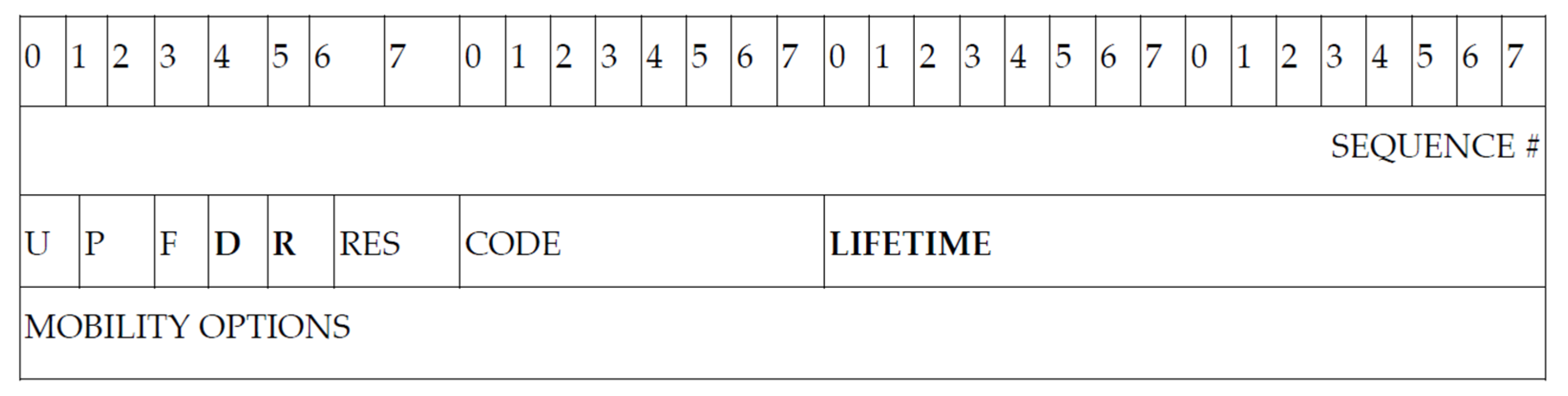
3.2. PMIPv6/AAND—Handover Message Format

Modifying the protocol as it is built today to suit the requirements of network service and standardization is complicated. As a result, the accumulation of an original IPv6 header would make it more difficult and hinder the network service. However, it is much more effective to add a new field in an old header. For this purpose, adding new flags to basic information like HI/HACK is being discussed. A similar method was adopted for erstwhile protocols based on MIPv6. The only two modified messages in F-PMIPv6 are HI and the HACK.
By utilizing the HI message, the PMIPv6/AAND assigns the M-MAG to the MN. Moreover, this M-MAG will be attached to the MN through the concerned MN-ID, MN prefix, and information about the concerned LR session. In the PMIPv6/AAND, the M-MAG is acknowledged by the HACK message. The concerned HI also presents the LR state information. Figure 4 and Figure 5 illustrate the customized form of the inventive HI and HACK messages, correspondingly. The recently initiated new fields are represented in bold and explained below.
D flag (PMIPv6/AAND flag): This is the new flag introduced in the proposed system. Here, the working mechanism of the HI message is derived from the F-PMIPv6 explained in [10]. Moreover, this flag value must be assigned as 1, if not, it turns into the F-PMIPv6 message. This flag value carries the LR information.
R flag (LRI flag): This novel flag is assigned as 1 to point out that it includes appropriate LRI information. If this is not the case, localized routing initiate (LRI) details will not cumulate in this message.

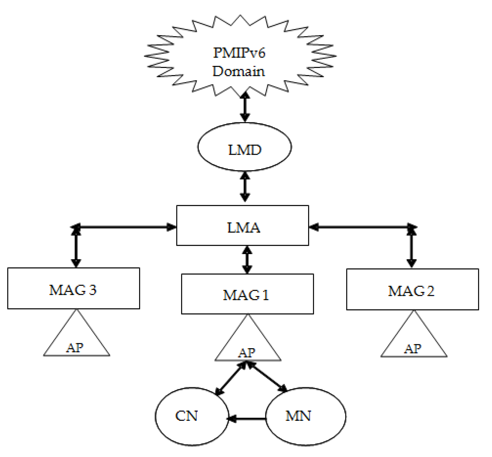
3.3. PMIPv6/AAND—Architecture

Figure 6 demonstrates multiple VIs of the projected mechanism architecture. Among the network layer and link layer there are several VIs paired to PIs. Every PI has a binding attribute and is bound to a VI. Two types of PI binding properties are present in the proposed architecture. One is a principal type (pci) and the other is a secondary type (sec).The packets are forwarded by the PI of the principal ‘pci’. The solid line is the main binding symbol. Except for the VI which has the ‘pci’ binding, the ‘sec’ type PI is tied with the VI. The dotted line in Figure 5 shows the PI’s ‘sec’ element. When the ‘sec’ type is used, the ‘pci’ PI and then the VI link become down. Every VI has a dissimilar PI. Every PI is tied with a ‘sec’ type to all VIs, except the PI which has the ‘pci’ binding. Here, the similar LL-ID is share with the ‘pci’ type PI and VI. This is very useful to identity neighbour discovery (ND) in a multi-virtual interface [1].

3.4. PMIPv6/ AAND—Various Multi-Homing Topologies

PMIPV6/AAND works powerfully on any single LMA, devoid of the reflection of the position of the MAG. PMIPv6/AAND consists of three topologies technique.
  • CN-MAG1-MN. (Without handover)
  • MN-MAG1; CN-MAG2; (Hand over between MN-MAG2 i.e., MAG1-MAG2)
  • MN-MAG1; CN-MAG2 (Hand over between MN-MAG3 from MAG1 to MAG3 through MAG2, i.e., MAG1-MAG-MAG3
In these different multi-homing situations, it is assumed that the localized routing route between MN and CN is already provided via the MAG address which is present in the same local mobility domain (LMD).

3.4.1. Topology 1—PMIPV6/AAND

The MN and the CN are annexed to the same MAG in Topology 1. The localized path between MN and CN has already been established. The packets are now being translated from MN to CN. If the MN and CN interface is modified, then the AAND fields hold the connection layer identifier (LL-ID) information, and those fields make the MN mobility continuous. Figure 7 displays the PMIPv6/AAND Multihoming Topology 1.

3.4.2. Topology 2—PMIPv6/AAND

Now the MN is linked to MAG1, and the CN to MAG2. The MN then shifts from MAG1 to MAG2. MAG1 is now known as P-MAG according to the CN. The P-MAG and the M-MAG are connected in Topology 2, to the same LMD. Now the packets are being moved via M-MAG from MN-CN. The handover between P-MAG and M-MAG occurs. The PBU list retains the P-MAG LL-ID using AAND fields when the MN changes its interface and allows for a successful mobility session. Figure 8 displays the PMIPv6/AAND Multihoming Topology 2.

3.4.3. Topology 3—PMIPv6/AAND

The MN is attached to MAG1 in this topology, and the CN node is attached to MAG3. The MN passes from MAG1 through MAG2 to MAG3. But between CN and MN, the LR path is created, and it is created only for the MAG concerned.
There is therefore a need for the re-establishment of a link between CN and MN with M-MAG, since there is another new MAG, i.e., MAG2 is inserted into the domain. The SAND field also provides the LL-ID information of the mobility with the MN-ID in Topology 3. Figure 9 displays the PMIPv6/AAND Multihoming Topology 3.

3.5. PMIPv6/AAND’s Signal Flow

According to the steps given below, the signal flow is carried. Figure 10 outlines the PMIPv6/AAND principle of regular signal flow.
  • CN passes packets via bi-directional tunnel among LMA and MAG 2 to the MN.
  • MAG gives a migration update to the mobility session, i.e., HI message to M-MAG which contains the message HNP that was transferred to the MN interface.
  • M-MAG sends an acceptance of migration to a mobility session i.e., HACK message to MAG as a reaction to the relocation of a connectivity session.
  • MN is added to M-MAG.
  • M-MAG passes a multi-prefix (HNP1, HNP2) proxy-binding update (PBU) message to LMA
  • LMA changes the Entry for Binding Cache.
  • LMA passes a multi-prefix alternative (HNP1, HNP2) proxy binding acknowledgement (PBA) message to LMA.
  • But CN will interact with MN on an ongoing basis.

3.6. PMIPv6/AAND with Multiple Virtual Interfaces

In the PMIPv6/AAND, every interface has its own neighbor cache (NC). Every IP address in the connection, along with its VIs and concerned LL-ID in the concerned network, is maintained by the NC. By setting the flag value as’ 1’ when the VI receives a neighbor solicitation (NS) message, it is received by the VI because the new field value is assigned by ‘1’. The neighbour advertising (NA) is responded to by the concerned VI with its LL-ID. Figure 11 explains the proposed method virtual interface concept.

4. Use Case and Simulation of the Proposed System

4.1. PMIPv6/AAND—Use Case

Figure 11 describes a use-case and simulation topology of the projected design. It is supposed that the handover of inter-technology is carried out from Physical Interface 1 (PI_1) to Physical Interface 2 (PI_2) at the same time as the MN communicates with the CN via PI_1.
The Home Network Prefix (HNP1) has the source and destination address of the concerned packets. These packets which are present in the HNP1 are transported through PI2 to CN. When the packets are received by MAG2, the packets are forwarded to the MAG2 routing table. If there is no HNP1 related routing entry in the routing table, the packets will be discarded or routed to default. The HNP1-related routing entry must therefore be maintained in the MAG2 binding update list (BUL). Here, every MAG is aware of the HNPs allocated to the MN prior to the transfer of inter-technology. The second reflection is the operation of ND in the PMIPv6 domain. This reflection relates to the multiple virtual interfaces of the architecture.

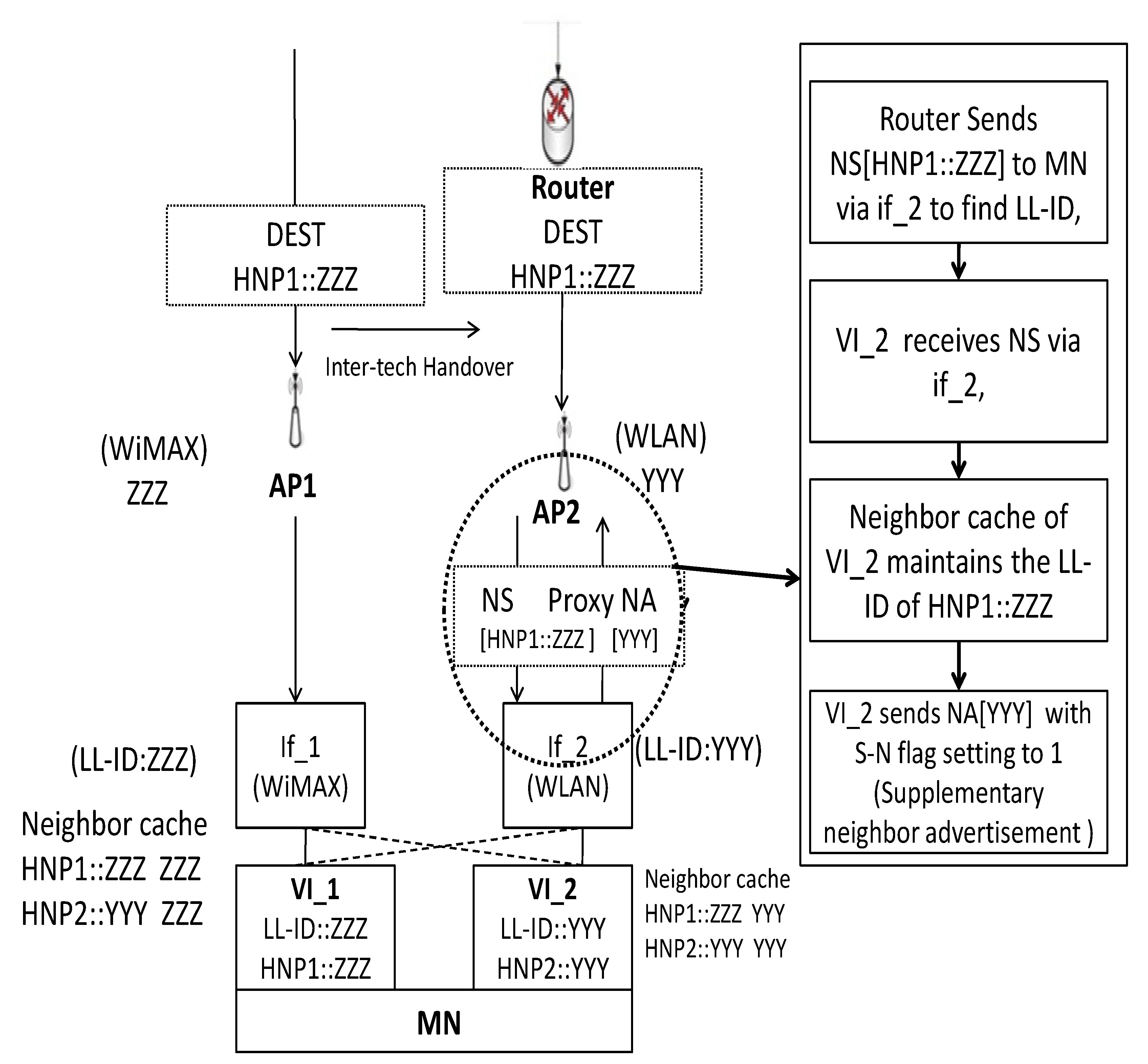
4.2. PMIPv6/AAND—Inter-Technology Handover

This section gives details on the post action of the inter-technology handover of PMIPv6/AAND with the multiple VIs. The activation and deactivation property of every HNP is present in the HNP list. The concerned property represents its activation state. The activated HNP is represented by the bold font, and the deactivated HNP state is represented by the ordinary font as in Table 1.

Concurrent Connection of PMIPv6/AAND

Once multi-homing MN binds to the MAG, the MAG sends a PBU to the LMA. As soon as the LMA is given the PBU message from the MAG, the LMA assigns the LL-ID to an HNP, although the MN-ID is alike and generates new BCEs. Table 1 represents the LMA BCE as soon as the virtual interface VI_1 is found via PI 1 towards the MAG1, as shown in Figure 12. The HNP1 is owed to MN VI_1.
Whenever the new HNP is allocated by the LMA, the LMA updates the HNP list for each entry that has the same MN-ID. Furthermore, each allocated HNP has a similar attribute to multiple VI’s. The HNP ‘pci’ type is used for the latest attached VI LL-ID, and the HNP ‘sec’ type is used for inter-technology handover. Table 2 shows the LMA BCE when the MN is mounted to the MAG2 using VI 2 through PI 2. The VI 2 is given HNP2. Once assigned HNP2, the LMA must update its HNP list of BCE entries linked to the same MN-ID.
The LMA posts the proxy binding acknowledgment (PBA) with the modified HNP list to the MAG following a modification of the BCE. The LMA also posts the message unsolicited PBA (UPBA) to other MAGs. The UPBA is used to synchronize the HNP list and is forwarded without the PBU message by the LMA. When the MAG is given the PBA message, the MAG’s binding update list (BUL) is added to the HNP list that is incorporated in the PBA message, and the MAG locates the routing table by HNP property.
If MN receives the packets associated with the deactivated HNP, the MAG updates the BUL’s HNP list and sends a PBU message to the LMA, which includes the updated HNP list. The PBU includes the additional information to advise inter-technology handover and updating of the HNP list.
Moreover, it includes one of the reserved field flags in PBU message format. While the inter-technology handover from PI 1 to PI 2 occurs, the MAG2 gets the HNP1-related packets as shown in Figure 12. The MAG2 could even recognize that inter-technology handover is being executed and will upload the PBU message for notification to the LMA. After the inter-technology handover, the LMA receives the PBU message from the MAG, and the LMA activates the banned HNP. Table 3 explains the state of the HNP list after triggering.
Since modifying the BCE, the LMA will forward the UPBA message for synchronization to each MAG associated with the same MN-ID in the BCE. HNP lists in the BCE connected to the same MN-ID should be synchronized. The MAG sets the routing table based on the HNP list included in the UPBA message when the MAG receives the UPBA message and updates the BUL’s own HNP list. Table 4 explains the MAG2 BUL following the receipt of the message from UPBA. When the MN receives the RS message, the MAG sends a RA message to the MN including the enabled HNP. Table 4 explains the state of the HNP list of binding update details.

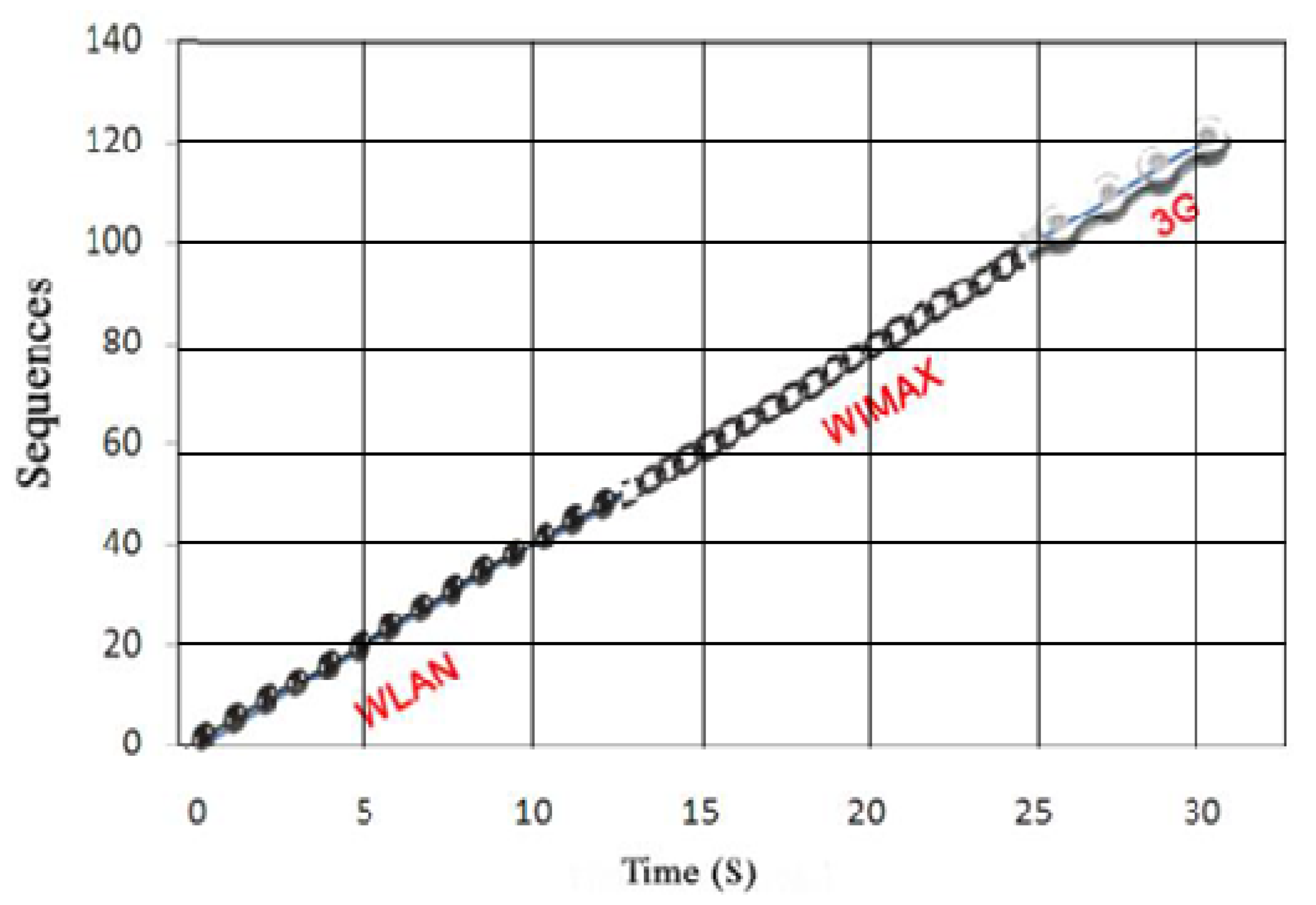
4.3. Description Performance Analysis and Simulation of PMIPv6/AAND

To assess the efficiency of the proposed Technique-1, the following parameters are used in PMIPv6/AAND within the system.
Here, MMAG represents the modified MAG (M-MAG) which also represents the number of hops in Hop Distance (HD). It is believed to be circular. It is determined using the Poisson distribution [11]. (Baumann and others, 1994).
Thus to enable the suggested system to be workable, the foregoing factors are considered in the simulation.
  • Use of stateless address configuration is presumed. The time delay of the connecting network prefix and its address interface is negligible.
  • Constant traffic between MN and CN is assumed, and the packets are transferred through the optimized path.
  • The RS and RA message are presumed to have the same time delay in attaching the MN.
  • The very first AP is known as a hop first.
  • The arrival and receiving session rates are the same.
The current proposal follows a Poisson process which calculates the packet’s total waiting time [12] (Kleinrock 1975).

Mobility Model Ratio

A mobility ratio is calculated based on the speed that the packets take to reach to the mobile node. It is represented as the signal mobility ratio (SMR).
SMR = Session arrival rate/average time delay between AP-MN
Session arrival rate is represented as ƛs. are shown the SMR value in the Equation (1)
SMR = λ s T D AP - MN
The simulation tool is a Network Simulator–3 (NS-3) [13] (http://nsnam.org/). Based on Choi et al. [14] (2010), the PMIPv6 setup is created. Figure 11 displays the topology of the simulation. The topology for simulation is conceived with three different physical interfaces such as WLAN, Wi-Max and 3G. For simulation, the following parameter values are given, and the simulation parameters are set because of the IEEE standard [15]. The linked delay (LD) is 0.1 msec (simulation is done with minimum velocity to effectively show the difference in the results of the transfer in seconds). Table 5 displays the parameter values for various interfaces in the simulation. The table below shows the parameters for PMIPv6, F-PMIPv6 and PMIPv6/AAND simulations. The simulation takes 30 seconds to run. The speed of motion is 100/Mbps (Megabits per second)
Here, it is desired to hit simulation from one MN to one CN. Table 6 represents BCE’s LMA flow binding list and shows the priority flow of the different interfaces.
The local link address is fixed during simulation as unique for all flow IDs, i.e., fe80: 200: bbee: aaff: ddcc, and the virtual interface ID is fixed as fe80::200:22ee: aa11:4433. The simulation’s priority value is set to display the flow transition between different MAGs (i.e., multi-homing). The simulation begins with Interface 1, i.e., (if 1, i.e., WLAN), and XX is the LL-ID. The simulation takes 30 seconds to run. The simulation begins at 0 seconds and once the simulation exceeds 0.5 seconds, the stream id is Y, i.e., if 2 (Wi-Max) enters the simulation, and if 3 (3G) joins the simulation, 1.0 seconds flow ID is Z. Table 7 represents the simulation flow ID details.

4.4. PMIPv6/AAND—Analysis and Simulation Results Based on Handover

The simulator NS-3 was used for the concerned work. The subsequent subsections clarify MIPV6, PMIPv6, F-PMIPv6 and PMIPv6/AAND handover. This segment explains the MN transfer execution with multiple interfaces. The simulation arrangement begins with its interface 1 (if_ 1) i.e., WLAN at 0 seconds, the second interface2 (if_2), i.e., Wi-Max, comes into the simulation at 11 seconds, and then the third interface 3 (if_3), i.e., 3G, comes into the simulation at 14.5 seconds. The following results are occupied at the 30th second of the simulation. The speed of mobility is 100 Mbps. Table 8 represents the concerned simulation parameters.

4.4.1. MIPv6—Handover Analysis

The transfer is analyzed according to the signal flow of MIPv6 [16]. It is calculated on the delay shown in the Equation (2) of the connection layer 2 establishments (TDL2), time delay classification of the MN with the new access router (TDNAR), time delay detection of the duplicate address detection (TDDAD), time delay of the binding update (TDBU) and the time delay of registration (TDREG).
HOD MIPv 6 = ( TD Auth + TD RRS ) + ( TD RS + TD RA ) + TD NAR + ( TD BUH + TD HBA ) + ( TD REG + TD BUC + TD CBA )

MIPv6—Handover Simulation Result

Here, the MN begins with its if_1, i.e., the WLAN. The next interface, if_2 Wi-Max, comes into the simulation at the 11th second, although the MN transmits its signal to Wi-Max at the 18th second. 3G comes into the simulation at the 24.5th second, although the MN hands its signal to if_3 3G after 30 seconds. According to the simulation, the link was lost when MN switches to the if_3 network, i.e., 3G. The subsequent graph represents the MIPv6 simulation performance with multiple interfaces. Figure 13 illustrates the transition of the MIPv6 (here the Y-coordinate describes the packet sequences of the UDP packet sequences from the MN to the CN, which are collected by the CN). At 11.3 seconds, the transfer of the packets from the if_1 to the if_2 is carried out.

4.4.2. PMIPv6—Handover Analysis

The transmission is analyzed based on the signal flow of PMIPv6 [17]. The MN is switching from one MAG to the next. The CN localized routing and the concerned HOD is estimated in the subsequent Equation (3)
HOD PMIPv 6 = Layer   2   connection + ( t PBA + t PBU ) + t RS + t RA + ( t AAAreq + t AAAres ) + TTD Data
Here, layer 2 association indicates the transmission delay between the MN-AP and AP-MAG. The control signal delay is indicated as (tPBU + tPBA), and the delay of authentication is indicated as tAAAreq+ tAAAres.

PMIPv6 Handover Simulation Result

Here, the MN begins with its if_1, i.e., the WLAN. Then if_2 i.e., Wi-Max, comes into the simulation at the 11th second, however the MN handover the signal to if_2 occurs at 13.9 seconds. Then, if_3 3G joins the simulation at the 24.5th second, but the MN handover of the signal to 3G occurs at the 28th second. Figure 14 shows the PMIPv6 handover graph.

4.4.3. F-PMIPv6—Handover Analysis

The transition is evaluated in conjunction with the signal flow of F-PMIPv6 based on [10,18]. In F-PMIPv6, a new link is created to make mobility faster. Therefore, the signal is transmitted twice to make the versatility session continuous.
In the predictive mode, the F-PMIPv6 HOD is determined as follows. There is a need for a delay in authentication because, in the predictive mode, the authentication of the registration takes place before the MN attachment. HOD of F-PMIPv6 value calculated on Equation (4)
HOD F - PMIPv 6   ( Proactive   Mode ) = Layer   2   connection + ( t AAAreq + t AAAres ) + ( t PBU + t PBA ) + 2 ( t RS + t RA ) + TTD Data

F-PMIPv6—Handover Simulation Result

Here, the MN begins with its if_1, i.e., the WLAN. Then if_2 i.e., Wi-Max, comes into the simulation at the 11th second, however the MN handover of the signal to if_2 occurs at 13.9 seconds. Then, if_3 3G joins the simulation at the 24.5th second, but the MN handover of the signal to 3G occurs at the 27th second. In Figure 15 are shown the Handover Simulation result of PMIPv6/F-PMIPv6.

4.4.4. PMIPv6/SAND—Handover Analysis

The PMIPv6/SAND, the HOD is determined as follows in the Equation (5). There is no need for a pause in authentication, because the authentication of the registration takes place in the predictive mode after the MN connection.
HOD PMIPv 6 / SAND = Layer   2   connection + 2 (   t PBA + t PBU ) + 2 (   t RS + t RA ) + TTD Data

PMIPv6/SAND Handover Simulation Result

Here, the MN begins with its present interface if_1 i.e., WLAN. Then the if_2 Wi-Max comes into the simulation at 11th second, yet the MN hands over its sign to if_2 (Wi-Max) at 14.5 seconds. Then, the if_3 i.e., 3G, comes into the simulation at the 24.5th second, however the MN hands over its sign to 3G at the 25.5th second. Figure 16 portrays the handover diagram of PMIPv6/SAND.

4.4.5. PMIPv6/AAND—Handover Analysis

In PMIPv6/AAND, the MN handover is determined by Equation (6).
HOD PMIPv 6 / AAND = Layer   2   connection + MAX   (   t RS ,   t RA ) + TTD Data
Here, the delay of authentication is not measured, since the tunnel is recognized after accepting MN’s request. Unless the handover is not efficient enough and 3GPP interface is utilized again, it is still worthwhile to continue with handovers rather than leave traffic on the 3GPP interface. Of course, the bigger the number of handovers conducted, the more likely the quality of service would deteriorate, necessitating the use of optimal decision-making strategies [19]. Moreover, the AAND field continues preceding the MAG details as well as giving the details of MN-ID to M-MAG. Consequently, there is refusal necessity of authentication and its delay. The concurrent action of RS and RA occur in the projected method. In comparison to other techniques, full authentication of a node is not required when it transfers to a new domain, allowing for secure and seamless handovers across domains. [20] Since the P-MAG details are preserved by the LL-ID, the router solicitation occurs animatedly, and this information is stored by the AAND fields. Therefore, in the proposed method, the maximum time of RS and RA is estimated for the handover of PMIPv6/AAND.

PMIPv6/AAND—Handover Simulation Result

Here, the MN begins with the present interface if_1 i.e., WLAN. Then, the next interface if_2 i.e., Wi-Max, comes into the simulation at the 13th second, yet the MN hands over its sign to if_2 i.e., Wi-Max, at 13.1 second. Then, the next 3rd interface if_3 i.e., 3G, comes into the simulation at 24.5 seconds, yet the MN hands over its sign to 3G at 24.9 seconds. Figure 17 portrays the handover diagram of PMIPv6/AAND.

4.5. Comparison of Various Handover Delay’s

Based on previous Equations (1)–(4), the subsequent Table 9 denotes the handover delays of various mobile IPv6 protocols such as MIPv6, PMIPV6, F-PMIPV6, PMIPv6/SAND and PMIPv6/AAND.

4.6. PMIPv6/AAND—Handover Comparative Analysis

The PMIPv6/AAND handover delay is judged against MIPv6, PMIPv6 and F-PMIPv6. The comparative outcomes are given in Figure 18. The handover latency for MIPv6 is higher since it is a protocol based on the host-based criteria. Therefore, MIPv6 transfers a very small number of packets in the concerned time. Moreover, it needs MN contribution through mobility. The F-MIPv6 handover latency is less than the PMIPv6 as it creates a new link for every transfer. However, the PMIPv6 does not make a new fast transfer link like F-PMIPv6. Although the F-PMIPv6 and PMIPv6 are IPv6 mobile proxy protocols, the transfer latencies are higher than the proposed technique, i.e., PMIPv6/AAND, because the F-PMIPv6 and PMIPv6 messaging format does not use auxiliary parameters to view the virtual interface information of the concerned MN. Based on various topology mechanisms present in the proposed system, the handover delay of PMIPv6/AAND is less than the PMIPv6/SAND. For of this reason, PMIPv6/AAND transfers a greater number of packet sequences than the existing protocols. Thus, PMIPv6/AAND provides minimum transfer latency compared to other mobility protocols.

5. Conclusions and Future Work

Based on the outcome of the projected performance, PMIPv6/AAND powerfully assists multi-homing mechanisms based on MVI using its AAND fields and various topologies. The AAND fields ‘D’ and ‘R’ preserve the multiple virtual interface information and successfully diminish the latency of the handover. The handover simulation outcomes illustrate that the PMIPv6/AAND affords superior performance, such as decreased handover latency, throughout the mobility of MN. The comparative study shows that the time delay of the handover in PMIPv6/AAND is condensed in comparison with the existing PMIPv6 protocols. The proposed technique can extend the support for software defined networks.

Author Contributions

Conceptualization, I.L.K. and F.A.-T.; Data curation, F.A.-T.; Formal analysis, I.L.K.; Methodology, I.L.K. and F.A.-T., R.S.; Project administration, F.A.-T.; Resources, R.S., R.P.; Software, I.L.K.; Supervision, R.P. and C.-H.H.; Validation, I.L.K. and C.-H.H.; Writing―original draft, I.L.K. and F.A.-T.; Writing―review & editing, R.P. and C.-H.H. All authors have read and agreed to the published version of the manuscript.

Funding

This research received no external funding.

Institutional Review Board Statement

Not applicable.

Informed Consent Statement

Not applicable.

Data Availability Statement

No new data were created or analyzed in this study.

Conflicts of Interest

The authors declare no conflict of interest.

References

  1. Kim, S.M.; Choi, H.Y.; Lee, H.B.; Min, S.G.; Han, Y.H. Multiple virtual interfaces to support multi-homing hosts in PMIPv6 network. In Proceedings of the 2012 IEEE Globecom Workshops IEEE, Anaheim, CA, USA, 3–7 December 2012; pp. 1047–1051. [Google Scholar]
  2. Gundavelli, S.; Melia, T. ‘Logical Interface Support for Multi-Mode IP Hosts’, Internet Engineering Task Force, Draft-ietf-netext-logical-interface-support-01.txt. 2010. Available online: https://datatracker.ietf.org/doc/html/draft-ietf-netext-logical-interface-support (accessed on 10 March 2021).
  3. Li, Y.; Kum, D.W.; Seo, W.K.; Cho, Y.Z. A multi-homing support scheme with localized shim protocol in proxy mobile IPv6. In Proceedings of the 2009 IEEE International Conference on Communications, Dresden, Germany, 14–18 June 2009; pp. 1–5. [Google Scholar]
  4. White, C.; LISP Mobile Node. Network Working Group D. Farinacci Internet-Draft D. Lewis Intended status: Informational D. Meyer Expires: April 26, 2012; CISCO Systems, Inc.: San Jose, CA, USA, 2011. [Google Scholar]
  5. Nordmark, E.; Bagnulo, M. Shim6: Level 3 multihoming shim protocol for IPv6. RFC 5533 2009. [Google Scholar] [CrossRef]
  6. Akella, A.; Maggs, B.; Seshan, S.; Shaikh, A. On the performance benefits of multihoming route control. IEEE/ACM Trans. Netw. 2008, 16, 91–104. [Google Scholar] [CrossRef]
  7. Hong, Y.G.; Youn, J.S.; Kim, H.J.; Hyun, T. Analysis of the usage of a logical interface in PMIPv6. In Proceedings of the Advanced Communication Technology (ICACT), 2011 13th International Conference on IEEE, Gangwon, Korea (South), 13–16 February 2011; pp. 1069–1074. [Google Scholar]
  8. Melia, T.; Gundavelli, S. Logical Interface Support for Multi-Mode IP Hosts; Internet Engineering Task Force (IETF): Fremont, CA, USA, 2010; Available online: https://datatracker.ietf.org/doc/draft-melia-netext-logical-interface-support/ (accessed on 10 March 2021).
  9. Indumathi, L.K.; Punithavathani, D.S. Performance Improvement of Proxy Mobile IPv6 for the Support of Multi-Homing. Wirel. Personal Commun. 2017, 96, 1653–1672. [Google Scholar] [CrossRef]
  10. Yokota, H.; Chowdhury, K.; Koodli, R.; Patil, B. ‘F. Xia’, Fast Handovers for Proxy Mobile IPv6. RFC 5949. 2010. Available online: https://datatracker.ietf.org/doc/html/rfc5949 (accessed on 10 March 2021).
  11. Baumann, F.V.; Niemegeers, I.G. An evaluation of location management procedures. In Proceedings of the Universal Personal Communications, 1994. Record, 1994 Third Annual International Conference on IEEE, San Diego, CA, USA, 27 September–1 October 1994; pp. 359–364. [Google Scholar]
  12. Kleinrock, L. Queueing Systems, vol. 1. 1975. Available online: https://www.wiley.com/en-us/Queueing+Systems%2C+Volume+I-p-9780471491101 (accessed on 10 March 2021).
  13. Henderson, T. ns-3 Tutorial. Available online: https://www.nsnam.org/docs/models/singlehtml/index.html (accessed on 10 March 2021).
  14. Choi, H.Y.; Min, S.G.; Han, Y.H.; Park, J.; Kim, H. Implementation, and evaluation of proxy mobile IPv6 in NS-3 network simulator. In Proceedings of the Ubiquitous Information Technologies and Applications (CUTE), 2010 Proceedings of the 5th International Conference on Ubiquitous Information Technologies and Applications, Sanya, China, 16–18 December 2010; pp. 1–6. [Google Scholar]
  15. Amendment to IEEE Std 802.11(TM)-2012. This Amendment Specifies Enhancements to the IEEE 802.11 Medium access Control (MAC) for Robust Audio Video (AV) Streaming, While Maintaining Coexistence with Other Types of Traffic. Available online: https://standards.ieee.org/findstds/standard/802.11aa-2012.html (accessed on 10 March 2021).
  16. Perkins, C.; Johnson, D.; Arkko, J. RFC 6275: Mobility Support in IPv6; Internet Engineering Task Force (IETF): Fremont, CA, USA, 2011; Available online: https://datatracker.ietf.org/doc/rfc6275/ (accessed on 10 March 2021).
  17. Gundavelli, S.; Leung, K.; Devarapalli, V.; Chowdhury, K. ‘B. Patil’, Proxy Mobile IPv6. RFC 5213. 2008. Available online: https://datatracker.ietf.org/doc/html/rfc5213 (accessed on 10 March 2021).
  18. Zhou, D.; Zhang, H.; Xu, Z.; Zhang, Y. Evaluation of Fast PMIPv6 and Transient Binding PMIPv6 in vertical handover environment. In Proceedings of the Communications (ICC), 2010 IEEE International Conference on Communications, Cape Town, South Africa, 23–27 May 2010; pp. 1–5. [Google Scholar]
  19. Leiter, Á.; László, B. A flow-based and operator-centric dynamic mobility management scheme for proxy mobile IPv6. Wirel. Commun. Mob. Comput. 2019, 2019, 4567317. Available online: https://www.hindawi.com/journals/wcmc/2019/4567317/ (accessed on 10 March 2021). [CrossRef]
  20. Zhang, L.; Ma, M.; Qiu, Y. An enhanced handover authentication solution for 6LoWPAN networks. Comput. Secur. 2021, 109, 102373. [Google Scholar] [CrossRef]
Figure 1. Network’s general multi-homing configuration.
Sustainability 13 11743 g001
Figure 2. Virtual interface maintained for different technologies of access.
Sustainability 13 11743 g002
Figure 3. Limitation of Single virtual Interface.
Sustainability 13 11743 g003
Figure 4. PMIPv6/AAND—Handover Initiate Message Format [9].
Sustainability 13 11743 g004
Figure 5. PMIPv6/ AAND—Handover Acknowledgement Message Format [9].
Sustainability 13 11743 g005
Figure 6. PMIPv6/AAND—Architecture with Multiple Virtual Interface Technology.
Sustainability 13 11743 g006
Figure 7. Topology 1—Multi-Homing of PMIPv6/AAND.
Sustainability 13 11743 g007
Figure 8. Topology 2—Multi-Homing of PMIPv6/AAND.
Sustainability 13 11743 g008
Figure 9. Topology 3—Multi-Homing of PMIPv6/AAND.
Sustainability 13 11743 g009
Figure 10. PMIPv6/AAND signal flow.
Sustainability 13 11743 g010
Figure 11. PMIPv6/AAND—Simulation Topology [9].
Sustainability 13 11743 g011
Figure 12. PMIPv6/AAND—support for Multiple Virtual Interface [9].
Sustainability 13 11743 g012
Figure 13. MIPv6—Handover Simulation Result [9].
Sustainability 13 11743 g013
Figure 14. PMIPv6-Handover Simulation Result [9].
Sustainability 13 11743 g014
Figure 15. PMIPv6/F-PMIPv6—Handover Simulation result [9].
Sustainability 13 11743 g015
Figure 16. PMIPv6/SAND—Handover Simulation result.
Sustainability 13 11743 g016
Figure 17. PMIPv6/AAND—Handover Simulation Result.
Sustainability 13 11743 g017
Figure 18. PMIPv6/AAND—Handover comparative analysis (based on packet transfer).
Sustainability 13 11743 g018
Table 1. Binding details to the cache before updating.
MN-IDCoALL-IDHNP List
MN-1Proxy CoA1XXXHNP1, Pci
Table 2. Binding Cache Details after Update.
MN-IDCoALL-IDHNP List
MN-1Proxy CoA1 (PCoA1)XXX[HNP1, Pci],[HNP2, sec]
MN-1Proxy CoA2 (PCoA2)YYY[HNP1, sec],[HNP2, Pci]
Table 3. Proxy Binding Updating List after Triggering.
MN-IDCoALL-IDHNP List
MN-1Proxy CoA1 (PCoA1)XXX[HNP1, Pci],[HNP2, sec]
[HNP1, Pci],[HNP2, sec]
MN-1Proxy CoA2 (PCoA2)YYY[HNP1, sec],[HNP2, Pci]
[HNP1, sec],[HNP2, Pci]
Table 4. MAG2 Binding Update details.
MN-IDCoALL-IDHNP List
MN-1Proxy CoA1 (PCoA1)XXX[HNP1, Pci],[HNP2, sec]
[HNP1, Pci],[HNP2, sec]
MN-1Proxy CoA2 (PCoA2)YYY[HNP1, sec],[HNP2, Pci]
[HNP1, sec],[HNP2, Pci]
Table 5. Simulation values of diverse interfaces.
InterfaceSpeed
WLAN84 Mbps
WI-MAX75 Mbps
3G1 Mbps
Table 6. LMA Binding flow list of BCEs.
Flow IDMN-IDLL-IDPriority of Flow
UDP1 X (WLAN)MN-1XX: XXWLAN->3G->Wi-Max
UDP2 Y (Wi-max)MN-1YY: YYWi-Max->3G->WLAN
UDP3 Z (3G)MN-1ZZ: ZZ3G->Wi-Max->WLAN
Table 7. Simulations Flow ID details.
Flow IDMN-IDLL-ID
X (WLAN)MN-1XX:XX
Y (Wi-max)MN-1XX:YY
Z (3G)MN-1YY:ZZ
Table 8. Simulation Parameters.
ParametersValues
Layer 2 connection (Delay between MN-AP & Delay between AP-CN)0.2 sec
Time Delay between MN to NAR (TDRS)0.015 sec
Time Delay between NAR to MN (TDRA)0.015 sec
TDDAD0.2 sec
TDBUH 0.2 sec
TDHBA0.2 sec
TDBUC0.2 sec
TDCBA0.2 sec
Layer 2 connection (Delay between MN-AP & Delay between AP-MAG0.2 sec
Delay between MAG to LMA (tRS)0.015 sec
Delay between MN to MAG (tRA)0.015 sec
Authentication Delay = (tAAAreq+tAAAres = (0.2 sec + 0.2 sec)0.4 sec
Delay of Control Signal = (tPBA+ tPBU) = (0.2 sec + 0.2 sec)0.4 sec
TTDData0.4 sec
PDL1024 bytes
ƛs100 Mbps
Table 9. List of various IPv6 mobility protocols.
ProtocolHandover Delay
MIPv6(TDAuth + TDRRS) + (TDRS + TDRV) + (TDNAR) + (TDBUH + TDHBA) + (TDREG +TDBUC + TDCBA) + TTDData
PMIPv6Layer 2 connection + (tPBA + tPBU) + tRS + tRA + (tAAAreq + tAAAres) + TTDData
F-PMIPv6Layer 2 connection + (tAAAreq + tAAAres) + 2(tPBA + tPBU) + 2(tRS + tRA) + TTDData
PMIPv6/SANDLayer 2 connection + 2(tPBA + tPBU) + 2 (tRS + tRA) + TTDData
PMIPv6/AANDLayer 2 connection + MAX (tRS,,tRA) + TTDData
Publisher’s Note: MDPI stays neutral with regard to jurisdictional claims in published maps and institutional affiliations.

