
Optimization of Cyclone-Type Rotary Kiln Reactor for Carbonation of BOF Slag

Abstract
:1. Introduction
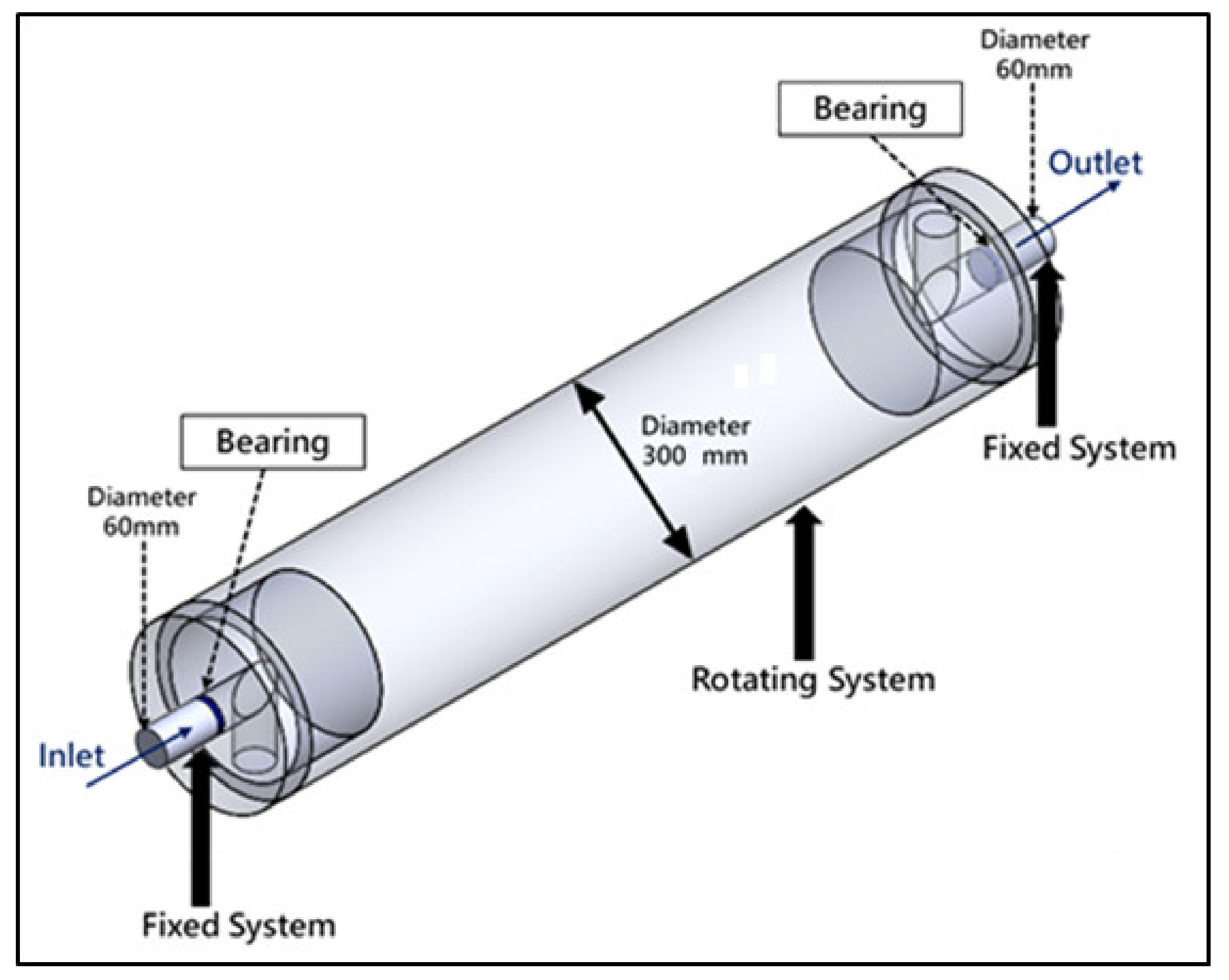
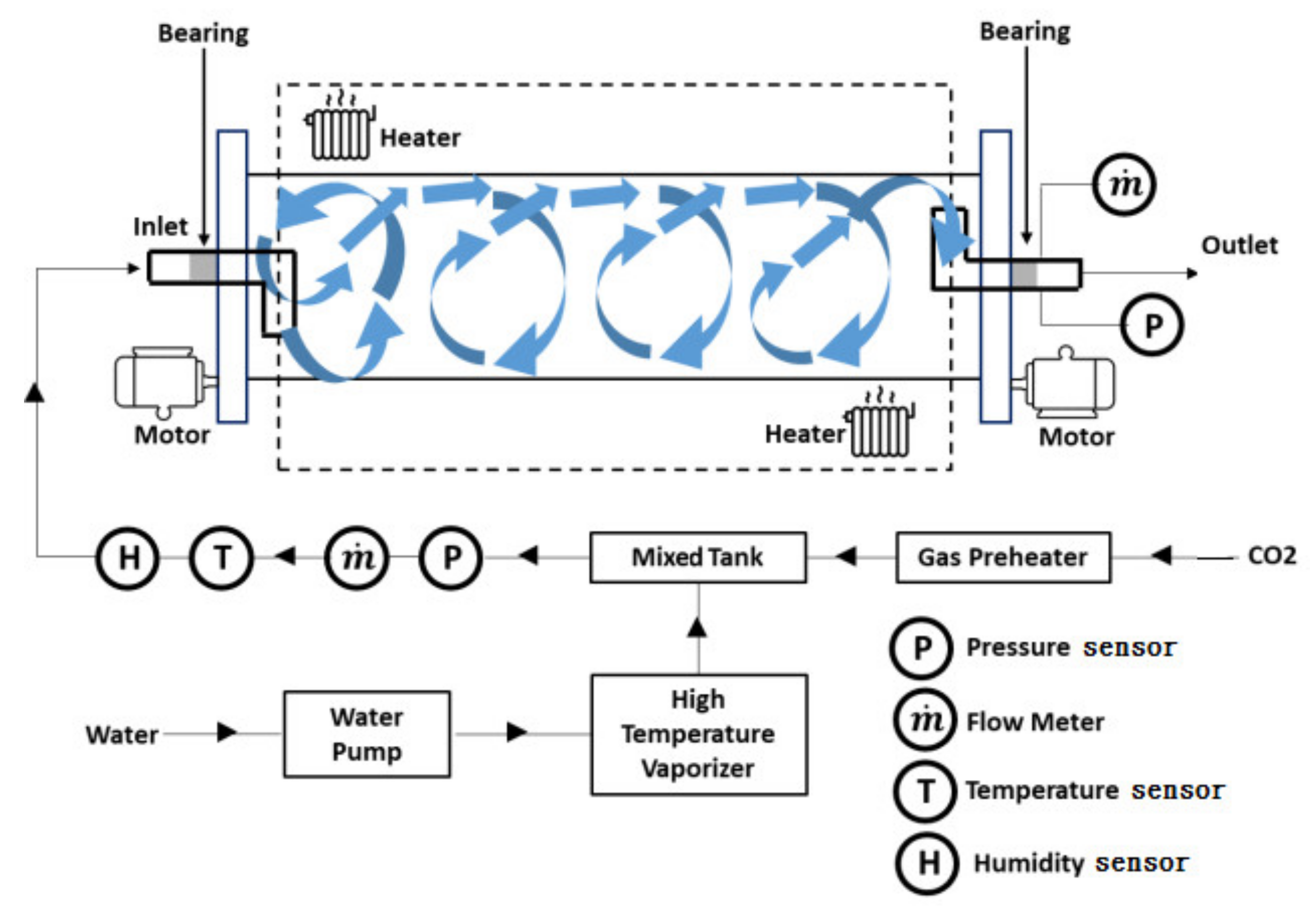
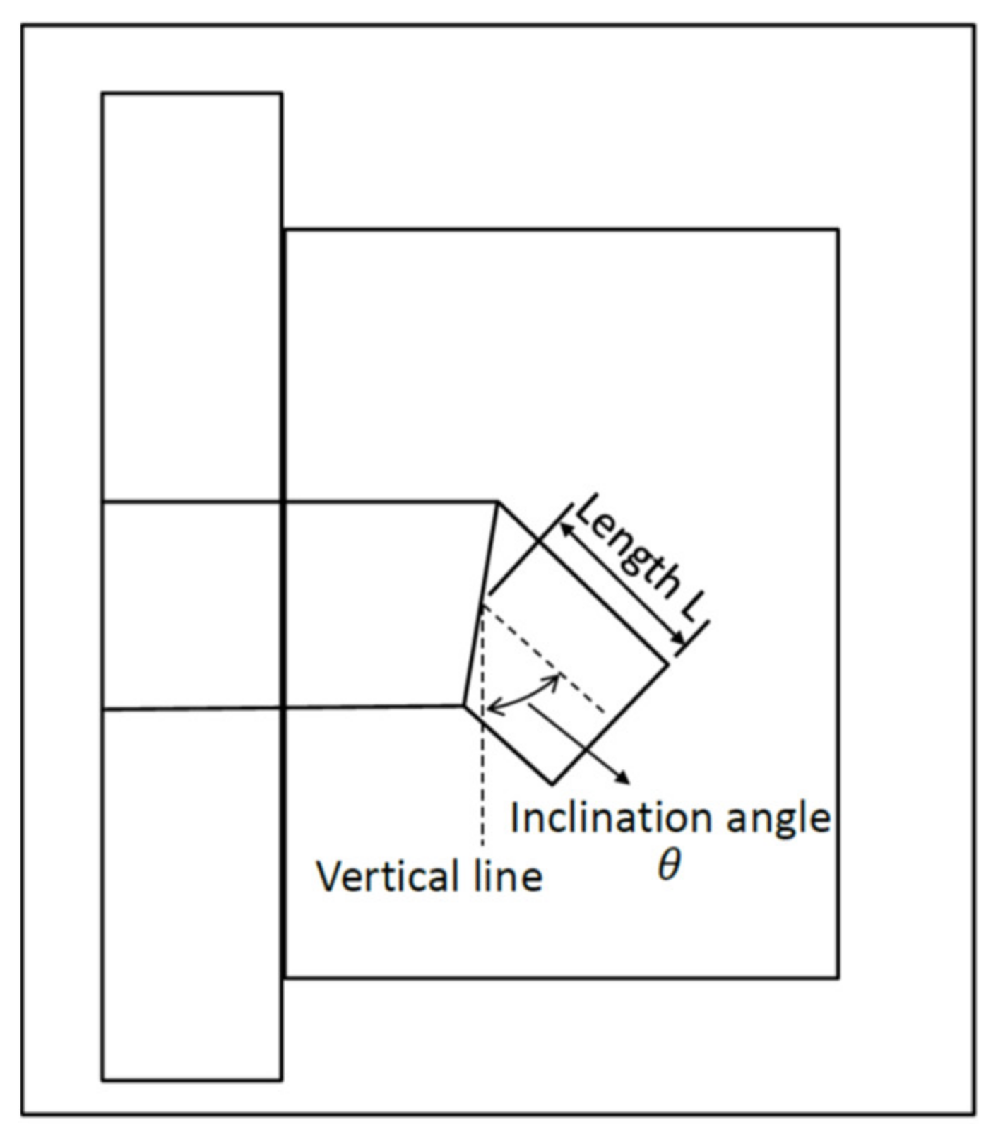
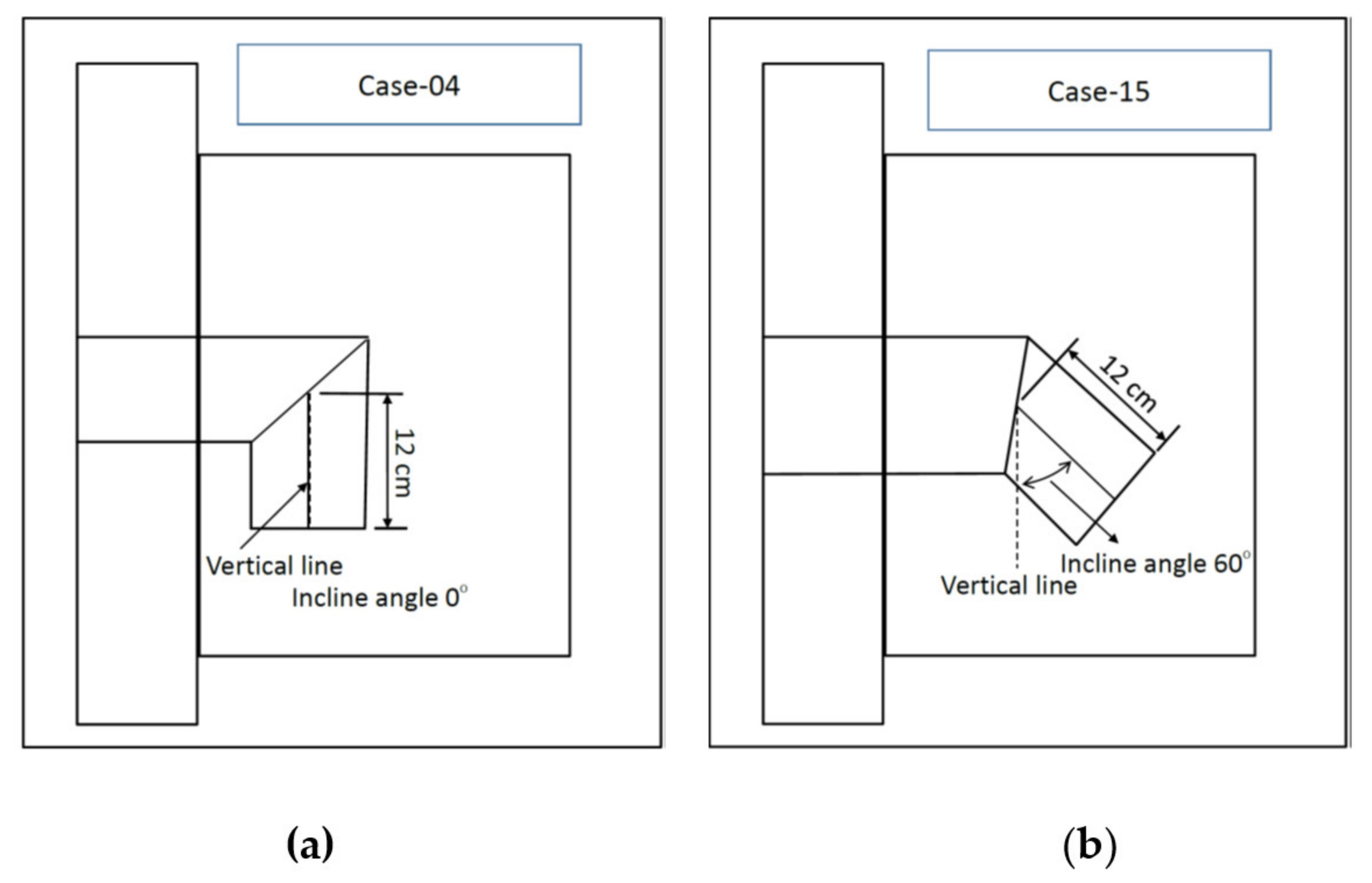
2. Reactor Model
3. Materials and Test Methods
3.1. BOF Slag
3.2. Carbonation Process
3.3. Thermogravimetric Analysis
4. Results and Discussions
4.1. CFD Simulation Results
4.2. Carbonation Experiments
5. Conclusions
- The Taguchi results have shown that the maximum CO2 residence time is achieved when using an inclination angle (θ) of 0° (i.e., parallel to the vertical line) and a bent tube length (L) of 120 mm.
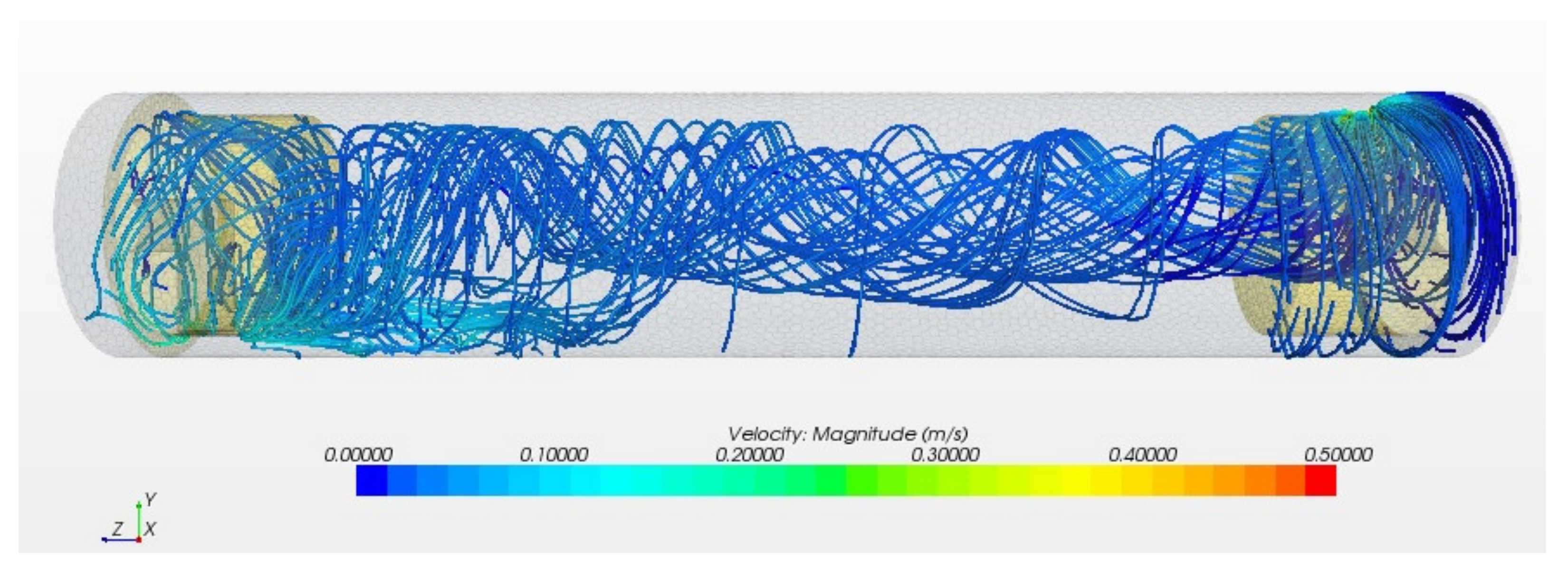
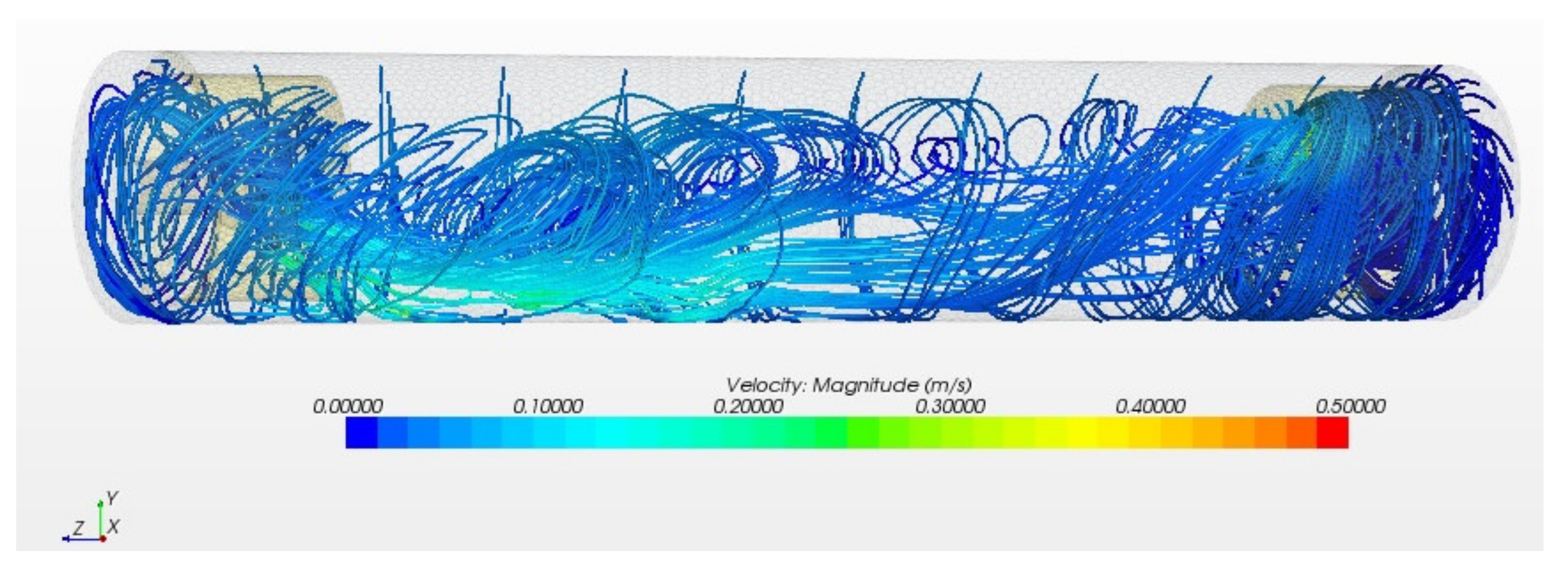
- The simulation results have shown that the CO2 gas residence time in the optimized cyclone-type rotary kiln (i.e., 101.08 s) is 38.05 s longer than that in the original (non-cyclonic) rotary kiln reactor (i.e., 63.03 s). In other words, the proposed design increases the carbonation reaction time by 60.4%.
- The experimental results have shown that the proposed cyclone-type rotary kiln achieves carbon dioxide absorption per kilogram of BOF slag of 16.00 g; representing an improvement of 31.7% over that of the original rotary kiln reactor, i.e., 12.15 g.
- In 2013, the annual production of BOF slag in Taiwan was about 1.5 million tons [18]. Based on the annual production of BOF slag, it is estimated that this study has a CO2 absorption potential of 24,000 tons/year in Taiwan.
Author Contributions
Funding
Institutional Review Board Statement
Informed Consent Statement
Data Availability Statement
Conflicts of Interest
References
- Shi, C. Characteristics and cementitious properties of ladle slag fines from steel production. Cem. Concr. Res. 2002, 32, 459–462. [Google Scholar] [CrossRef]
- Motz, H.; Geiseler, J. Products of steel slags an opportunity to save natural resources. Waste Manag. 2001, 21, 258–293. [Google Scholar] [CrossRef]
- Altun, I.A.; Yılmaz, I. Study on steel furnace slags with high MgO as additive in Portland cement. Cem. Concr. Res. 2002, 32, 1247–1249. [Google Scholar] [CrossRef]
- Santos, R.M.; Ling, D.; Sarvaramini, A.; Guo, M.; Elsen, J.; Larachi, F.; Beaudoin, G.; Blanpain, B.; Gerven, T.V. Stabilization of basic oxygen furnace slag by hot-stage carbonation treatment. Chem. Eng. J. 2012, 203, 239–250. [Google Scholar] [CrossRef] [Green Version]
- Pan, S.Y.; Eleazar, E.G.; Chang, E.E.; Lin, Y.P.; Kim, H.; Chiang, P.C. Systematic approach to determination of optimum gas-phase mass transfer rate for high-gravity carbonation process of steelmaking slags in a rotating packed bed. Appl. Energy 2015, 15, 23–31. [Google Scholar] [CrossRef]
- Ghasemi, S.; Costa, G.; Zingaretti, D.; Bäbler, M.U.; Baciocchi, R. Comparative Life-cycle Assessment of Slurry and Wet Accelerated Carbonation of BOF Slag. Energy Procedia 2017, 114, 5393–5403. [Google Scholar] [CrossRef]
- Polettini, A.; Pomi, R.; Stramazzo, A. CO2 sequestration through aqueous accelerated carbonation of BOF slag: A factorial study of parameters effects. J. Environ. Manag. 2016, 167, 185–195. [Google Scholar] [CrossRef] [PubMed]
- Jiang, Y.; Ling, T.G. Production of artificial aggregates from steel-making slag: Influences of accelerated carbonation during granulation and/or post-curing. J. CO2 Util. 2020, 36, 135–144. [Google Scholar] [CrossRef]
- Chang, J.; Wang, D.; Fang, Y. Effects of mineralogical changes in BOFS during carbonation on pH and Ca and Si leaching. Constr. Build. Mater. 2018, 192, 584–592. [Google Scholar] [CrossRef]
- IPCC. IPCC Special Report on Carbon Dioxide Capture and Storage; IPCC: Geneva, Switzerland, 2005. [Google Scholar]
- Inoue, R.; Suito, H. Hydration of crystallized lime in BOF slags. ISIJ Int. 1995, 35, 272–279. [Google Scholar] [CrossRef]
- Bertos, M.F.; Simons, S.J.R.; Hills, C.D.; Carey, P.J. A review of accelerated carbonation technology in the treatment of cement-based materials and sequestration of CO2. J. Hazard. Mater. 2004, 112, 193–205. [Google Scholar] [CrossRef]
- Lun, Y.; Zhou, M.; Cai, X.; Xu, F. Methods for improving volume stability of steel slag as fine aggregate. J. Wuhan Univ. Technol. Mater. Sci. Edit. 2008, 23, 737–742. [Google Scholar] [CrossRef]
- The Iron and Steel Institute of Japan (ISIJ). Production and technology of iron and steel in Japan during 2008. ISIJ Int. 2009, 49, 749–770. [Google Scholar] [CrossRef]
- Pan, S.Y.; Chiang, P.C.; Chen, Y.H.; Tan, C.S.; Chang, E.E. Kinetics of carbonation reaction of basic oxygen furnace slags in a rotating packed bed using the surface coverage model: Maximization of carbonation conversion. Appl. Energy 2014, 113, 267–276. [Google Scholar] [CrossRef]
- Pan, S.Y.; Lafuente, A.M.L.; Chiang, P.C. Engineering, environmental and economic performance evaluation of high-gravity carbonation process for carbon capture and utilization. Appl. Energy 2016, 170, 269–277. [Google Scholar] [CrossRef]
- Ding, J.; Wang, Y.; Gu, R.; Wang, W.; Lu, J. Thermochemical storage performance of methane reforming with carbon dioxide using high temperature slag. Appl. Energy 2019, 250, 1270–1279. [Google Scholar] [CrossRef]
- Ko, M.S.; Chen, Y.L.; Jiang, J.H. Accelerated carbonation of basic oxygen furnace slag and the effects on its mechanical properties. Constr. Build. Mater. 2015, 98, 286–293. [Google Scholar] [CrossRef]
- Chang, T.B.; Lee, C.Y.; Ko, M.S.; Lim, C.F. CFD Simulations of Rotary BOF Slag Carbonation Kiln Reactor with Cyclone Flow. Proc. Inst. Mech. Eng. Part E J. Process. Mech. Eng. 2020, 234, 37–45. [Google Scholar] [CrossRef]
- Lee, H.H. Taguchi Methods: Principles and Practices of Quality Design; GAU LIH BOOK CO.: New Taipei City, Taiwan, 2002. [Google Scholar]


| Diameter of reactor | 300 mm |
| Length of reactor | 1500 mm |
| Diameter of inlet/outlet tubes | 60 mm |
| Rotation speed of reactor | 2 rpm |
| Flow rate of CO2 | 1 L/s |
| Code | Control Parameter (Unit) | Level 1 | Level 2 | Level 3 | Level 4 |
|---|---|---|---|---|---|
| A | Inclination angle θ (°) | 0 | 30 | 45 | 60 |
| B | Length L (mm) | 30 | 60 | 90 | 120 |
| No: | A Level | B Level | Inclination Angle θ (°) | Length L (mm) |
|---|---|---|---|---|
| 1 | 1 | 1 | 0 | 30 |
| 2 | 1 | 2 | 0 | 60 |
| 3 | 1 | 3 | 0 | 90 |
| 4 | 1 | 4 | 0 | 120 |
| 5 | 2 | 1 | 30 | 30 |
| 6 | 2 | 2 | 30 | 60 |
| 7 | 2 | 3 | 30 | 90 |
| 8 | 2 | 4 | 30 | 120 |
| 9 | 3 | 1 | 45 | 30 |
| 10 | 3 | 2 | 45 | 60 |
| 11 | 3 | 3 | 45 | 90 |
| 12 | 3 | 4 | 45 | 120 |
| 13 | 4 | 1 | 60 | 30 |
| 14 | 4 | 2 | 60 | 60 |
| 15 | 4 | 3 | 60 | 90 |
| 16 | 4 | 4 | 60 | 120 |
| Experimental Run | Inclination Angle θ (°) | Length L (mm) | Residence Time (s) |
|---|---|---|---|
| 1 | 0 | 30 | 84.140 |
| 2 | 0 | 60 | 89.574 |
| 3 | 0 | 90 | 97.077 |
| 4 | 0 | 120 | 101.08 |
| 5 | 30 | 30 | 72.089 |
| 6 | 30 | 60 | 78.625 |
| 7 | 30 | 90 | 78.146 |
| 8 | 30 | 120 | 82.743 |
| 9 | 45 | 30 | 70.731 |
| 10 | 45 | 60 | 79.041 |
| 11 | 45 | 90 | 74.642 |
| 12 | 45 | 120 | 80.181 |
| 13 | 60 | 30 | 70.333 |
| 14 | 60 | 60 | 69.444 |
| 15 | 60 | 90 | 55.818 |
| 16 | 60 | 120 | 57.007 |
| Average Residence Times of CO2 Gas | |
|---|---|
| Original rotary kiln | 63.03 s |
| The proposed cyclone-type rotary kiln | 101.08 s |
| CO2 Absorption per Kilogram of BOF Slag (g/kg) | |
|---|---|
| Original rotary kiln | 12.15 |
| The proposed cyclone-type rotary kiln | 16.00 |
Publisher’s Note: MDPI stays neutral with regard to jurisdictional claims in published maps and institutional affiliations. |
© 2021 by the authors. Licensee MDPI, Basel, Switzerland. This article is an open access article distributed under the terms and conditions of the Creative Commons Attribution (CC BY) license (https://creativecommons.org/licenses/by/4.0/).
Share and Cite
Ko, M.-S.; Chang, T.-B.; Lee, C.-Y.; Huang, J.-W.; Lim, C.-F. Optimization of Cyclone-Type Rotary Kiln Reactor for Carbonation of BOF Slag. Sustainability 2021, 13, 11556. https://doi.org/10.3390/su132011556
Ko M-S, Chang T-B, Lee C-Y, Huang J-W, Lim C-F. Optimization of Cyclone-Type Rotary Kiln Reactor for Carbonation of BOF Slag. Sustainability. 2021; 13(20):11556. https://doi.org/10.3390/su132011556
Chicago/Turabian StyleKo, Ming-Sheng, Tong-Bou Chang, Cho-Yu Lee, Jhong-Wei Huang, and Chin-Fong Lim. 2021. "Optimization of Cyclone-Type Rotary Kiln Reactor for Carbonation of BOF Slag" Sustainability 13, no. 20: 11556. https://doi.org/10.3390/su132011556