Article

Requalification of RC Frame Apartment Buildings: Comparison of Seismic Retrofit Solutions Based on a Multi-Criteria Approach

School of Engineering, University of Basilicata, 85100 Potenza, Italy
*
Author to whom correspondence should be addressed.
Sustainability 2021, 13(17), 9962; https://doi.org/10.3390/su13179962
Submission received: 23 July 2021 / Revised: 25 August 2021 / Accepted: 27 August 2021 / Published: 6 September 2021

Abstract

:
Increasing environmental concerns are leading to measures and incentives aimed at reducing the energy consumption of buildings, which must be accompanied by substantial mitigation of seismic and structural risk. As for technical issues, it is important to select effective solutions specifically for medium-size RC apartment buildings (e.g., 3–6 storeys), which is where a large share of the Italian population lives today. To this end, it is important to compare, among other factors, the direct and indirect costs related to alternative techniques, thus allowing stakeholders (mainly private) and designers to select the most suitable solution for each case at hand and, finally, to speed up the design process. In this paper, different seismic strengthening techniques are designed and applied to a case study RC frame building that is representative of the EU building stock. An in-depth comparison is made with the aim of showing the advantages and disadvantages of different choices, mainly based on required costs and possible disruptions, keeping the targeted structural performance equal. Specifically, the possibility of disruption is a key point in hastening or, more frequently, hindering the implementation of the decision. In fact, people’s hesitation to leave their home, as well as the difficulty and high costs involved in finding temporary apartments if many people are involved, generally prevent such interventions from taking place. For this reason, some state-of-the-art techniques—that have minimum impact on non-structural elements, that can be applied only on the outside, and that can still provide an effective seismic retrofit—are examined and critically compared in the paper through a multi-criteria decision-making method.

1. Introduction

In recent decades, structural engineers have paid a great deal of attention to reducing the seismic vulnerability of buildings, developing a wide variety of seismic strengthening techniques and approaches to interventions [1]. Increasing environmental concerns have led to life-cycle cost assessment (LCCA) techniques that have helped in quantifying the effects of retrofitting interventions, in terms of not only initial costs but also greenhouse gas emissions during the service life of buildings [2]. This more comprehensive approach to assessing the sustainability of retrofitting interventions has led to ideas for upgrading strategies focused on reducing both earthquake losses and energy consumption [3]. This approach must consider the large quantity of buildings in Europe that have inadequate performance in terms of both seismic and thermal concerns and the related economic consequences in terms of the financial resources of EU Member States. As an example, in Italy alone, there are over 12.5 million residential buildings (mostly with masonry structure). Many of them were constructed before any seismic or energy efficiency regulations were enforced [4]. It is worth noting that most buildings have already reached the end of their service life, which, referring to modern codes, can be assumed to be 50 years. This highlights that maintenance problems can be found in older buildings, and then refurbishment is needed to enhance the service life without neglecting functionality problems and discomfort based on old approaches to the architectural conception of buildings, especially those included in social housing.
For these reasons, the European Commission promoted a pilot project, “Integrated techniques for the seismic strengthening and energy efficiency of existing buildings”, led by the Joint Research Centre (JRC) [5]. The project involves the development of a strategy for building requalification at the European level based on the state of the art regarding traditional and novel upgrading techniques, identifying priority regions, implementing measures, engaging stakeholders, and developing a communication strategy. As for the identification of priority regions, the project highlights that seismic-prone regions [6] are areas where there is generally also lower well-being of the population, and thus, refurbishment of the building stock is most needed. This could provide further benefits with the development of new jobs and increased employment. Therefore, the applicability and convenience of the seismic component of an integrated (seismic–energy) intervention is of paramount importance.
For this reason, the ReLUIS-DPC research project [7] worked on developing low-impact techniques for the seismic strengthening of buildings that can be applied at a local or global level, and delivered publicly available technical reports describing case studies that applied seismic retrofit techniques combined with energy efficiency measures [8,9]. The intense research activity at the European and Italian levels has been accompanied by measures implemented to promote the refurbishment of private buildings in Italy. Among them, the Superbonus 110% initiative [10] is a legislative measure that provides tax advantages to building owners who decide to adopt seismic retrofitting and energy upgrading interventions. This tax exemption may also be assigned to a third party (e.g., a banking institution) in the form of a tax credit. By accessing this measure, owners can make interventions completely for free, and this can significantly influence the choice of technical solution adopted for seismic retrofitting. Moreover, since this measure has a fixed deadline, it is important to use low-impact techniques that require short construction time as much as possible.
Based on this background, many research groups developed new techniques for seismic retrofitting using low-impact approaches [11]. For example, a local technique to improve beam-column joints’ seismic performance in RC frame buildings is shown in [12], while the solution proposed in [13] provides a brand-new system for the realization of dissipative exoskeletons for seismic retrofitting of RC buildings. Regarding the promising effectiveness of exoskeleton solutions, it is also important to highlight studies that set up design methods [14], which are important to provide practical tools for the optimization of design choices.
In summary, many retrofit strategies are currently available based on both traditional and innovative materials, and commercially available to building industry professionals. Therefore, selecting the most suitable retrofit solution for an individual building may not be an easy task. Frequently, among different alternatives, it is difficult to identify the best one according to a variety of factors that cannot be measured with the same units. For these reasons, multi-criteria decision making (MCDM) methods are helpful in choosing the most suitable solution for the particular structure at hand [15]. They allow the ranking of alternative solutions according to a variety of criteria that can be set based on the specific intervention problem.
In this study, the Technique for Order Preference by Similarity to Ideal Solution (TOPSIS) [16] MCDM method is used to rank different retrofit solutions applied to a case study building. The TOPSIS method involves a procedure that evaluates different retrofit solutions based on a series of criteria selected by the owner/user/manager of the building. Once the criteria are selected, which can be either quantitative (e.g., intervention cost or duration of work) or qualitative (e.g., architectonical impact or invasiveness), relative weights must be assigned to them in order to decide which are the most important. Further details of the procedure are reported in [16].
This paper deals with the application of three seismic retrofit solutions to a four-storey RC apartment building in order to compare them and highlight the pros and cons of each one, as well as to decide which is the most suitable for the building. First of all, the three techniques are described: local strengthening with a CAM system [17,18] (essentially consisting in a steel jacketing technique in which transverse elements are made of stainless-steel ribbons), precast exoskeleton system [19] and seismic isolation [20]. These three retrofit options are selected in order to highlight differences among traditional solutions based on interventions at the local level and others intended to minimise the impact of work inside the building, thus reducing disruptions and consequent social and financial costs as much as possible. Therefore, a building already subjected to previous studies [21] is described, along with the seismic assessment and designed retrofit interventions according to the selected solutions.
Finally, the seismic performance and cost evaluation is carried out for the three retrofit solutions, also applying the mentioned MCDM method to identify the most suitable solution for the building. The retrofit solutions are evaluated based on seven criteria: intervention cost, duration of work, seismic performance, incidence of costs for the adaptation of systems, architectonical and functional impact, invasiveness and durability. Judgments according to these criteria are given by individuals representing the actors involved in the decision-making process: a structural engineer, an architect, a building administrator and a private citizen (as tenants). Applying the MCDM approach shows that the availability of financial incentives can influence the final decision, as well as which criteria are the most important among the selected ones.

2. Seismic Strengthening Techniques

There is a wide variety of technical options available for seismic strengthening of RC buildings, which has even increased in recent years. In their analysis of a large database of about 5700 buildings damaged after the 2009 L’Aquila earthquake, Di Ludovico et al. [22,23] found that the most commonly used techniques for repairing/strengthening heavily damaged RC buildings were FRP composite systems (58%), RC jacketing (23%), steel jacketing (21%) and base isolation (11%). It is also worth noting that interventions were frequently carried out on infill walls (20%), emphasizing the role of non-structural components in the seismic performance of RC buildings.
Experimental and numerical studies have been devoted to developing new solutions at either the local or global level, mostly keeping in mind the minimisation of the impact on use. On the other hand, new solutions often require more advanced materials and/or construction methods with respect to traditional ones, which may be carried out by unskilled workers. Moreover, RC frame buildings can be strengthened by using local techniques that can prevent fragile collapse, enhancing the global ductility and avoiding an increase in the total base shear transferred to the foundation, thus avoiding the need for invasive and expensive interventions.
For these reasons, three technical solutions are selected based on the level of invasiveness, the type of approach (local or global) and the need for intervention on the foundation. The first one is a local strengthening technique named CAM, which involves strengthening of both columns and beams to obtain higher strength and ductility. The second one uses precast RC exoskeletons, which act to increase the global strength and stiffness of the building. An exoskeleton works as a second skin made of a new RC frame that captures part of the seismic forces from the existing structure. Finally, the third investigated retrofit solution is the well-known base isolation, which falls within the global techniques.
The selected retrofit solutions are briefly presented and discussed in the following sections.

2.1. Retrofit Solution S1: Local Strengthening

The selected local strengthening solution is the active confinement of masonry (CAM) technique, first developed for the seismic upgrading of masonry buildings. Afterwards, it was applied to RC elements [17], exploiting its ability to provide confinement for column elements [17,18] and work as a jacketing system. CAM involves placing steel angles along the RC framing members’ corners wrapped with post-tensioned stainless-steel ribbons, which applies confinement pressure to the concrete. The shear strength is also increased, as suggested by EC8 [24].
To also obtain increased flexural strength, the angles of the framing members must be connected to each other to provide continuity and transmission of flexure stresses [18].
It is worth noting that strengthening through CAM differs from previous steel jacketing solutions due to the use of ribbons in place of steel plates to connect the angles. The ribbons are flexible and do not need any welding, allowing faster application with respect to traditional steel jackets. The ribbons are installed by means of a tool that provides the required pre-stress. It is important to highlight that cement mortar beds between the steel angles and the RC members’ corners are needed to prevent stress peaks and obtain an effective steel-to-concrete bond. As with most local strengthening techniques, steel jacketing can be combined with energy retrofitting techniques such as window replacement, heating/cooling system upgrading, roof insulation, and so on. Moreover, given the limited increases in thickness of RC members due to steel jacketing, the technique can be combined with an exterior insulation finishing system that is applied to the building envelope.

2.2. Retrofit Solution S2: Precast Exoskeleton

Different exoskeleton solutions, in terms of structural shape and materials, were recently proposed [25,26]. In this study, the precast exoskeleton technique recently patented by the authors [19] is used as the seismic strengthening solution.
It consists of fully precast RC external frames connected to the existing RC structure to work as the main lateral load-bearing system (Figure 1). The exoskeleton is made by assembling precast beam–column subassemblies (see detail in [19]), which are connected to each other by bolted steel flanges that provide structural continuity.
The connection between the exoskeleton and the existing structure is realized by means of shear anchors bonded with epoxy resin, designed to resist the shear forces transferred from the existing structure to the exoskeleton. The design and detailing of the precast exoskeleton are based on the performance target of the upgraded structure, which will be either upgrading or retrofitting. In this way, the strength and stiffness of the exoskeleton are found in order to comply with code regulations and allow the existing structure to not exceed its seismic capacity. Afterwards, the precast joints of the exoskeleton are designed according to the code prescription for new RC members.
This solution mostly allows dry installation (i.e., without cast-in-place elements). Moreover, in case of damaging earthquakes, it permits the replacement of beam–column joints. The presence of an exoskeleton allows support for new infill systems that reduce the thermal transmittance of the building envelope, thus improving energy efficiency. It is worth noting that this kind of strengthening solution needs a newly constructed foundation system, which avoids increased stress on the existing foundation, although it has an additional cost with respect to the exoskeleton’s superstructure.
Even more than local strengthening solutions, exoskeletons are suitable for combination with energy efficiency upgrading interventions. However, an improvement of the envelope’s thermal performance can be obtained by realizing a new infill system inside the exoskeleton plus an eventual exterior insultation finishing system. In this case, an integrated seismic-energy retrofitting intervention is performed, instead of a simple combination of single energy and structural interventions.

2.3. Retrofit Solution S3: Seismic Base Isolation

Seismic base isolation, also known as base isolation [27,28,29,30], is a popular technique for protecting structures against earthquakes. It can substantially decouple the superstructure from its substructure, thus protecting the building from life loss or damage to non-structural components. This technique is commonly employed for the seismic protection of new structures, especially strategic buildings (e.g., hospitals) or transportation infrastructure (bridges). Moreover, its use has become more common in the upgrading/retrofitting of existing buildings [31].
Base isolation leaves the building elevation (above the isolation layer) almost unchanged and, therefore, there is full compatibility between seismic and energy upgrading interventions. To allow crossings through to the isolation layer, the systems’ adaptation requires special attention. In fact, flexible connections are necessary to allow seismic displacements.

3. Selection of Case Study and as-Built Seismic Assessment

According to the last Italian census involving both population and houses [4], the Italian building stock amounted to about 12 million buildings. Most of them are masonry structures (more than 7 million), and about 3.7 million are reinforced concrete. Due to the prevalence of masonry buildings, more than half have 1–3 storeys (low-rise buildings, according to HAZUS [32]), and were mainly built before the 1970s. After that time, RC structural types with more storeys became prevalent [33]. In general, the Italian building stock is lacking in seismic design. Indeed, until 1981 (when a large seismic classification started), only about 25% of the territory was classified as seismic, and consequently, most of the residential buildings (about 77%) were designed only for vertical loads.
In Italy, design rules can be classified according to two macro-periods, pre- and post-1971 [34]. The former is generally characterized by low-quality concrete [35] and smooth steel [36]. On the contrary, in the early 1970s, two fundamental laws (n. 1086, 5 November 1971 [37] and n. 64, 2 February 1974 [38]) were enforced to guarantee better construction quality of structures, while materials with better mechanical properties were generally adopted.
The considered case study building is a four-storey RC framed structure located in Potenza (a town in southern Italy), dating back to the post-1971 period and designed to withstand only vertical loads using the simulated design procedure described in [39]. The building has a rectangular shape (Figure 2a) with total dimensions of 21.4 × 11.8 m2 for the X and Y directions, respectively. It has a constant inter-storey height of 3.05 m. Due to the slab (25 cm thick) orientation, beams supporting the vertical load are present in only the X direction, and they have five bays (only two where the staircase is present). Deep beams are placed on the perimeter, with cross-section dimensions of 0.30 × 0.50 m2). Along the transverse X direction, the structure has three bays covered only by the slab. Columns have cross-section dimensions of mainly 0.30 × 0.30 m2, except for some elements of the lower storeys, with dimensions of 0.30 × 0.40 m2. The staircase (Figure 2b) has an eccentric position with respect to the Y direction and no eccentricity regarding the X direction. The stairs have a knee-type beam with dimensions of 0.30 × 0.50 m2.
The case study building was subjected to a seismic assessment, according to the Italian seismic code [40], by means of a nonlinear static analysis (pushover) using commercial software (Pro_Sap by 2Si [41]), and thus followed a procedure that is commonly used by practitioners. More specifically, macro-modelling based on lumped plasticity was adopted to describe the non-linear flexural response of each RC member. Bi-linear bending moment–rotation relationships were defined by considering the chord rotation expressions (at yielding and ultimate) reported in the commentary on the Italian seismic code (Ministerial Circular 7/2019) and were identical to those reported in the EC8-3 European code regulations [24], which were basically derived from the studies by Panagiotakos and Fardis [42]. Bending moments were calculated by assuming a parabola–rectangle relationship for concrete under compression and an elastic–perfectly plastic stress–strain relationship for tensile steel. A step-by-step procedure also allowed us to check the status of brittle elements by comparing shear demand and related capacity; the latter was evaluated by taking into account cyclic shear degradation due to ductility demand according to the model proposed by Biskinis [43].
As mentioned above, reinforcement details were already known from previous studies in which the building design was simulated while applying the rules that have been in force in Italy since 1971.
The material properties are as follows:
  • Concrete was assumed to have mean cylinder compressive strength equal to f c m = 20   MPa , which is in accordance with typical values for RC buildings constructed between 1971 and 1982 [35].
  • Reinforcing steel was assumed to belong to deformed FeB38k class steel, with a mean yielding stress equal to f y k = 375   MPa .
It is important to note that the Italian seismic code requires a reduction in the mean values of material properties using the confidence factor (FC), which depends on the knowledge level (KL). In this case, the best KL is assumed (KL3) and consequently FC = 1. Therefore, the assessment analysis was conducted using the mean strength values.
The assessment was conducted with respect to both the life safety limit state (SLV) and damage limitation limit state (SLD) (Figure 3). According to the Italian seismic code, safety indices are expressed as ratios between seismic capacity and demand; for example, in terms of peak ground acceleration value:
ζ E _ S L V = a g _ S L V P G A 475 y
where a g _ S L V is the ground acceleration that causes the first element’s collapse and P G A 475 y = 0.202   g is the peak ground acceleration for a return period T R = 475 years (i.e., with an exceedance probability of 10% in 50 years) based on the class of use of the specific residential building (class II, according to [40]) for the site of Potenza. The assumed ground type and topographic category are B and T1, respectively. Indeed, the seismic hazard is rather high, since the town of Potenza is located in seismic zone 1 (among four zones with decreasing hazard from 1 to 4).
Regarding the damage limitation state:
ζ E _ S L D = a g _ S L D P G A 50 y
where a g _ S L D is the ground acceleration causing the structure to reach the deformation limit of 0.5% (for brittle non-structural elements attached to the structure) and P G A 50 y is the peak ground acceleration for a return period T R = 50 years (i.e., with an exceedance probability of 63% in 50 years).
Performance indices with respect to SLV and SLD can be used jointly to evaluate the average earthquake annual loss (EAL) with an index called PAM, introduced by Ministry of Infrastructure Decree no. 65 in 2017 [44]. The PAM index allows us to obtain the seismic classification of a building considering losses due to damage to both structural and non-structural elements. The PAM index is used in this study to express the global seismic performance of the building in both the as-built and post-intervention conditions. Table 1 shows the results in terms of PAM, ζE_SLV and ζE_SLD.

4. Design of Retrofit Interventions

Retrofit solution S1 is intended to increase ductility by strengthening 32 beams, 44 columns and 48 beam–column joints (Figure 4a,b). This is achieved by using the CAM system with stainless-steel ribbons that are 0.9 mm thick and 19 mm wide. Their tensile strength is equal to ftk = 950 MPa. Elements placed at RC member corners are 60 × 60 × 6 mm L-profiles of grade S275 steel according to the Italian building code [40]. For 12 of the 32 beams, confining is performed by using one ribbon layer spaced 14 cm at the ends (i.e., next to plastic hinges). For the other beams, 20 cm spacing is used. The 28 most stressed columns have a full-length distribution of one-layer ribbons spaced from 9 to 17 cm depending on the need for shear strengthening. The remaining columns have 30 cm spacing. On external and corner beam–column joints, six ribbons are placed along the height, each with six layers. The total intervention cost, evaluated according to the Basilicata Region price list for construction [45] and the price list used for repair and reconstruction in the aftermath of the 2016–2017 Central Italy earthquake [46], is equal to 281 €/mq. The latter is evaluated while also taking into account construction site security costs, in situ tests for the evaluation of material properties, design and assessment, and VAT costs. The intervention cost without these ancillary expenses is equal to 231 €/mq. The duration of work is 115 days with a team of six workers.
The S2 retrofit solution is carried out by using four reinforced concrete external frames (Figure 5) connected to the existing structure by means of ϕ16 mm shear connectors spaced 40 cm apart. The cross-sections of RC members and related reinforcement were defined to ensure suitable reductions in the existing eccentricity on each floor between the centres of mass and stiffness. This results in better dynamic behaviour of the structure. In this regard, the new frame in the X direction (the one farthest from the staircase) has columns that are rotated 90° with respect to the others.
All exoskeleton columns have rectangular cross-sections of 0.4 × 0.6 m2. As for the beams, in the longer frames only, the first and second levels have a 0.4 × 0.6 m2 section, and the third and fourth levels have 0.4 × 0.5 m2 cross-section. Shorter frames have 0.4 × 0.7 m2 beams on the first two levels and 0.4 × 0.5 m2 on the last two. In addition, 20 mm diameter longitudinal reinforcement bars and 8 mm diameter stirrups (spaced 14 cm apart) are used for the beams. Columns have 20 mm and 16 mm longitudinal bars, and 8 mm hoops (15 cm spacing is used).
The exoskeleton’s foundation is a rectangular beam with a 1.2 × 0.8 m2 cross-section reinforced with 20 mm diameter bars and 8 mm diameter stirrups (12 cm spacing). The concrete used for all RC members is grade C28/35 and the reinforcing steel is class B450c [40]. The full intervention cost [45,46] is 218 €/mq. The cost of intervention without ancillary expenses (as mentioned before) is 171 €/mq. However, the latter includes the cost of system relocation during construction of the foundation beam, which is estimated as 10% of the total. The duration of work is 61 days with a team of six workers.
The S3 retrofit solution is aimed at reducing seismic demand by means of a base isolation system. Specifically, the isolation system, made of 16 elastomeric devices and 8 multidirectional sliders, is placed at the top of the first-storey columns. For this purpose, a steel bracing system made of HEA140 profile trusses (grade S275 steel) is realized to stiffen the first storey (Figure 6a). The cost of the retrofit solution [45,46] is 301 and 245 €/mq with and without ancillary costs, respectively. These values include the expenses for system adaptation (installation of flexible joints for all systems passing through the isolation plan to allow relative displacement between superstructure and substructure), which amounts to 5% of the total. The duration of work is estimated at 48 working days.
It is worth highlighting that cost of system adaptation for seismic isolation is lower compared to exoskeletons since it requires only internal adaptation of pipes and wires crossing the isolation layer. In fact, flexible connections are needed to allow relative displacement between the superstructure and the substructure. On the contrary, when systems need to be adapted on the building exterior to allow the construction of a new foundation (as in the case of solution S2), service suppliers (water, gas, electricity, telephone and internet operators) must be consulted, and this possibly causes additional delays and cost.

5. Post-Intervention Seismic Performance

Figure 7 shows a comparison of the seismic performance of the selected retrofit solutions, using the envelope of capacity curves in retrofitted and as-built condition derived from pushover analyses. In particular, solution S1 (local strengthening) provides a simultaneous increase in global resistance and ductility, while S2 (exoskeleton) provides a significant increase in global resistance, leaving the ultimate lateral displacement capacity of the building essentially unchanged. Solution S2 (seismic isolation), unlike the previous ones, allows the building to be retrofitted by reducing the seismic demand below the capacity of the original structure. For this reason, no capacity curve is reported, and the isolation system design and seismic capacity assessment were carried out by linear dynamic analysis.
Table 2 shows the capacity demand ratio values for the selected retrofit solutions with respect to damage limitation (ζE_SLD) and life safety (ζE_SLV). The average annual earthquake loss is evaluated according to the Italian guidelines on seismic classification (PAM), which take into account seismic performance related to the two limit states. While life safety performance is rather similar among the selected alternatives, with ζE_SLV slightly above the required value for retrofit (ζE_SLV = 1.0), the damage limitation is very different, being just sufficient for S1 (ζE_SLD = 1.01), and largely redundant for S3 and especially for S2 (ζE_SLD = 1.30 and ζE_SLD = 2.62, respectively). The combination of risk indices is reflected in PAM values, which are more favourable for S2, in which lower earthquake annual loss is expected.

6. Multi-Criteria Comparison

The selection of the optimal retrofit strategy is carried out through a multi-criteria decision-making process. The used method is TOPSIS [16], which involves a procedure based on the following steps: (i) seismic assessment of the as-built structure, (ii) selection and definition of retrofit solutions, (iii) design and assessment of post-intervention condition related to the different retrofit options, (iv) selection of criteria to evaluate alternatives, (v) relative weighting of the criteria, (vi) evaluation of the alternatives, (vii) application of the chosen MCDM method to rank the alternatives and identify the most suitable retrofit solution and (viii) sensitivity analysis to investigate the stability of the solution with respect to the weights of the criteria.
Steps (i) to (iii) were shown in the previous sections. The remaining steps are shown in the following sections.

6.1. Selection of Evaluation Criteria

The evaluation criteria can be either quantitative or qualitative depending on whether they can be measured or not. Seven criteria were selected to evaluate the three retrofit solutions (Table 3), among which four are quantitative (C1–C4) and three are qualitative (C5–C7). Beside the intervention cost (C1) and the work duration (C2), it is important to evaluate the seismic performance (C3) in order to compare different options and the cost of eventually adapting the systems (C4), which is related to additional invasiveness and disruption. This latter is evaluated as the percentage with respect to the total intervention cost. It is a cost share related to interventions that may cause additional delays and disruption as it requires third party actions (e.g., relocation of water, gas, electricity supplies). Among the qualitative criteria, it is important to evaluate the architectonic and functional impact (C5) in order to determine the extent to which the aesthetics of the building and its usability are impacted by the intervention. Invasiveness (C6) is mainly related to the need for work inside the building that forces tenants to abandon their dwellings for a certain period, with consequent social and economic disadvantages. The durability (C7) of a certain alternative is related to how much maintenance is needed for newly installed or retrofitted components during their service life.

6.2. Comparison of Criteria

It is worth noting that each of the selected criteria needs to be weighted with respect to the others in order to set their relative importance in the full evaluation of different retrofit solutions. This is achieved by using the method proposed by Saaty [47], which is based on pairwise comparisons of criteria and the analysis of eigenvalues. Considering two criteria, Cj and Ck (j, k = 1, 2, …, 7), the relative importance of Cj with respect to Ck must be defined according to different linguistic definitions, reported in Table 4, which are then converted into numerical values.
By comparing criteria according to the mentioned method on a pairwise basis, a series of a j k values that populate an n × n matrix (A) is obtained, where n is the number of selected criteria. Values on the matrix diagonal are always 1, since a j j derives from the comparison of Cj with itself. Moreover, it is always the case that a j k = 1 / a k j .
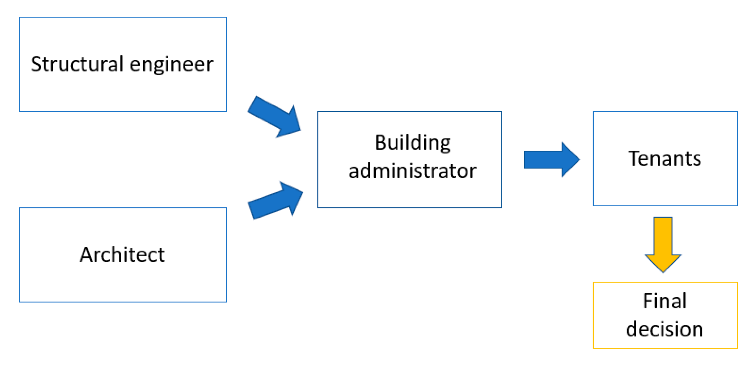
Comparing criteria for weighting is not an easy task, since it can be influenced by the subjective evaluation of the decision-maker. In case of private buildings, the final decision makers are the tenants, who are often the owners, according to the widespread Italian custom of buying a home. It is true, of course, that choices of tenants are affected by counselling from building administrators, engineers in charge of the structural design (eventually complemented by an energy efficiency upgrade), and architects in charge of resolving architectural and functional issues. For these reasons, four subjects were charged with filling the A matrix to represent an architect (Arch.), a structural engineer (Eng.), a building administrator (Admin.) and a private citizen who could be a tenant (Ten.) (Figure 8). All subjects were adequately educated on the TOPSIS method and, in particular, on how to make pairwise comparisons.
In addition, external factors can influence the comparison of criteria. For example, the existence of financial incentives, as is currently the case in Italy [10], could make it possible to attribute a lower importance to criterion C1, related to the intervention cost, which is completely supported by public funds in the form of tax discounts. However, this will not be a permanent condition, since incentives usually expire after a certain period. In case of the presence of stores on the ground floor of the building, the work duration can assume high importance. On the other hand, disruption due to invasive retrofit work is recognized as one of the most significant restraints on the massive rehabilitation programme, supported by the current Italian incentive legislation, which is aimed at economic growth to recover from the COVID-19 crisis. Therefore, many people would identify disruption as the most important criterion for evaluating a retrofit solution.
From the above background, different versions of matrix A were considered in this study. Basically, the four individuals filled in two versions of the matrix, considering either the presence or absence of financial incentives, to finally obtain eight versions of the consequent relative weights for matrix A (Table 5, Table 6, Table 7 and Table 8).
Once the pairwise comparisons are carried out to determine the A matrices, a consistency evaluation related to the DMs is needed. The consistency evaluation is satisfied when, given a criterion Ci that is judged to be more important than criterion Cj by factor a i j , and a criterion Cj that is in turn judged to be more important than criterion Ck by factor a j k , the result is that Ci is judged to be more important than Ck by factor a i k = a i j · a j k .
To this end, the so-called consistency index (CI) can be calculated as follows:
C I = λ m a x n n 1
where λ m a x is the maximum eigenvalue of the A matrix. CI has to be normalized by the random consistency index (RCI), which is an average random consistency factor depending on n (Table 9). The ratio C I / R C I is the consistency ratio (CR). Consistency control is considered satisfactory when CR is less than 5% if n = 3, 9% if n = 4, and 10% if n > 4.
Once the consistency control is passed, the vector (W) of relative weights w1, w2, …, w7 can be determined as the principal right eigenvector. Otherwise, pairwise comparisons must be redone to achieve the minimum required consistency.
For the case under consideration, the vectors of weights and the related CR values are reported in Table 10 and Table 11.
In the absence of incentives, the highest weights are attributed to criteria C1 (intervention cost), C3 (seismic performance) and C6 (invasiveness), and in the presence of incentives they are C3, C6 and C7 (durability). The presence of incentives shifts the decision-maker’s attention from intervention cost to durability. In fact, a strengthening solution with low durability would force tenants to face maintenance expenses in a probable future period without incentives.
Moreover, the best consistency (lower CR values) is obtained by technicians (Eng. and Arch.), as would be expected, while for non-technical individuals (Admin. and Ten.) CR values are near the upper limit of 10%. Table 10 and Table 11 also show columns with the average of the four weight vectors that will be assumed in the following evaluations. It is assumed that the final decision is influenced by all actors involved in the decision-making process.

6.3. Ranking of Retrofit Solutions

The TOPSIS method [16] is based on a concept which states that the best solution is the one with the minimum distance from an ideal solution A* and, therefore, the maximum distance from the “anti-ideal” solution A-. Assuming xij as the measure of the performance of the ith solution (i = 1, 2, 3) with respect to the jth criterion (j = 1, 2, …, 7), all values xij (3 × 7 = 21) are collected in decision matrix D = [xij] (Table 12).
Regarding criteria C5, C6 and C7, due to their “qualitative” nature, only linguistic judgments can be expressed. To apply the TOPSIS method, it is, therefore, essential to convert these qualitative variables into “quantitative” ones by once again adopting the Saaty eigenvector method [47].
Qualitative pairwise comparisons were made between the different solutions Si as a function of the degree of compliance with the considered criterion, and the procedure was carried out separately for C5, C6 and C7. The pairwise comparison was made by only two individuals out of the selected four, the engineer and the architect, since it requires technical skills in the building sector.
By adopting the linear Saaty scale (Table 4), these judgments were then converted into numbers aij in the range 1/9–9. In this case, with reference to Table 4, the “relative importance” aij should be interpreted as the relative measure of the degree of compliance with the considered criterion of the alternative Si with respect to Sj. Once all values aij are in a 3 × 3 matrix (reported in Table 13 and Table 14 for each qualitative criterion), Saaty’s method defines the elements of the main eigenvector as a quantitative measure of the performance of each retrofit solution with respect to the qualitative criterion under consideration. The binary comparisons in the matrices were entrusted to the expert judgment of the architect (Table 13) and the structural engineer (Table 14). The quantitative measure of each solution Si is reported in Table 15.
A consistency ratio lower than 5% (acceptability threshold) indicates that there is a good degree of consistency among the expert judgments provided by the two compilers.
Accounting for the heterogeneity of the xij D matrix coefficients, normalization is necessary in order to obtain the R = [rij] matrix. The latter represents the normalized decision matrix.
r i j = x i j k = 1 3 x k j .
The normalized decision matrix R = [rij] is reported in Table 16.
Subsequently, all values of the ith column of the R matrix are multiplied by the weight wi of the ith criterion (“Average wi” column in Table 10). The weighted normalized decision matrix V = [wj rij = vij] is reported in Table 17.
The ideal A* and the anti-ideal A- solutions (Table 18) are obtained by putting together the best and worst performance with respect to each of the seven criteria for the three retrofit solutions (S1, S, S3).
Criteria from C1 to C6 can be classified as “cost” criteria, which require minimisation of their values to improve the intervention performance with respect to them. The opposite is true for criterion C7 (durability), which is a “benefit” type and should be maximized. Therefore, in defining the ideal and anti-ideal solutions, it is necessary to interpret the maximum value as the “best” performance for “benefit” type criteria and the minimum value for “cost” type criteria.
Each real or ideal retrofit solution can be represented by a point in a seven-dimensional space where the jth axis measures the normalized and weighted performance of the considered alternative with respect to the generic criterion Cj. Then, the geometric distance d i * of the solution Si (i = 1, 2, 3) from the ideal A*, and the distance di- of Si from the anti-ideal A-, can be obtained with the following expression:
d i * = j = 1 7 ( v i j v j * ) 2
where vj* and vj- represent the jth element of the vectors of seven elements (Table 18) constituting the alternatives A* and A-. The values of the distances d i * and di− are shown in Table 19. Once the distances d i * and di− of the alternative Si (i = 1, 2, 3) are obtained from the solutions A* and A-, respectively, the relative distance of the retrofit solution from the ideal solution is obtained from the following ratio:
C i * = d i d i + d *
C i * values for the three retrofit solutions are in the range [0.0–1.0]. According to the TOPSIS method, the solution ranking is conducted according to C i * values. The most suitable is the one with maximum C i * . In this case, in the absence of incentives, the most suitable solution is S3 (base isolation), with C i * = 0.732 (Table 19). The exoskeleton solution (S2) is second, and local strengthening (S1) would be the least favourable solution.
Starting from Table 16 reporting the normalized decision-making matrix Rij, the same procedure was again applied, using the “Average wi” column in Table 11, which was obtained considering the availability of financial incentives (Table 20 and Table 21). This allowed to obtain Table 20 reporting the weighted decision-making matrix and Table 21 reporting the ideal and anti-ideal solutions.
In this case, the more suitable solution (Table 22) is S2 (exoskeleton), while retrofit solution S1 (local strengthening) is always ranked third.
By applying the TOPSIS multi-criteria decision-making method, local strengthening retrofit options result in less suitable solutions for the building type under consideration. In both assumed scenarios (presence/absence of incentives), global techniques such as exoskeleton (S2) and seismic isolation (S3) are more suitable because they are less invasive. The possibility of intervening from the outside without having to relocate tenants has great value and can be important in the final decision.
When external or public financial resources are available in the form of either tax discounts or grants, decision makers shift their focus to the durability of the retrofit solution. In this regard, the exoskeleton solution is judged to be more durable compared to base isolation, which may involve expensive replacement of isolation devices due to effects of aging on their constitutive materials. As shown in Table 22, C i * is equal to 0.735 for S2 and 0.684 for S3, with a 7% difference.
In the opposite situation, that is, without financial incentives, the most suitable solution is base isolation. In this case, the cost of system adaptation has a negative influence on S2 (exoskeleton), which requires a new foundation system with demanding excavation work along the building perimeter, while the cost of the same work for S3 is lower. However, careful evaluation is required, since, as can be seen from Table 19, the difference in C i * between S3 and S2 is only 3%, and a slight increase in this parameter could invert the ranking positions.
The results obtained in terms of ranking can be considered to be generally valid for building types such as the one considered here, which is largely widespread in Italy and the Mediterranean area. However, considering a different building type and varying levels of seismic hazard (which is assumed high in this study) could lead to different results.

7. Conclusions

Within the framework of an urgent need for seismic strengthening interventions in the residential building stock in Italy, this study compares different retrofit solutions based on both local and global intervention strategies. After describing the design of interventions for seismic retrofit of a case study building, to support the decision-making process, the retrofit solutions are compared based on seven criteria that measure—either qualitatively or quantitatively—their performance with respect to specific aspects related to such interventions. Multi-criteria decision-making requires pairwise comparisons of criteria to assign them relative weights. This was carried out by subjects involved at different levels of the decision-making process in order to ensure that the final decision-maker (owner(s)) would take a decision based on external suggestions and advice.
The three retrofit solutions (S1 (local strengthening with CAM jacketing), S2 (precast exoskeleton) and S3 (seismic base isolation)) were compared assuming two reference scenarios: one that is currently in force in Italy, where huge financial incentives are available (up to 110% of the intervention cost), and one without any public grants.
Relative weights show that intervention cost (C1) and seismic performance (C3) are judged the most important, along with invasiveness (C6), when no financial incentives are available. The latter, in fact, often discourages tenants from undertaking a building retrofit due to the discomfort created by the disruptive work, which often forces them to abandon their dwelling for a period.
On the contrary, when financial incentives are available, the attention moves from intervention cost to durability (C7), since it can avoid delayed expensive and invasive maintenance interventions due to material degradation.
In both assumed scenarios, global techniques such as exoskeleton (S2) and seismic isolation (S3) are more suitable than local strengthening (S1) because they are less invasive. The possibility of intervening from the outside without having to relocate tenants has great value and plays a major role in the final decision.
If financial incentives are available, the exoskeleton alternative is more suitable, since ordinary maintenance can guarantee a long lifetime of the RC members that constitute the external frames, thus satisfying the durability criterion. In the opposite case, i.e., in the absence of incentives, base isolation is better due to the lower cost of system adaptation (C4). Nevertheless, a careful evaluation of such costs should always be performed, since the difference in C i * between S3 and S2 is very small and a slight increase in this parameter for S3 could invert the ranking positions, making the exoskeleton more suitable.
In this context, taking into account the seismic strengthening target (full retrofit), local strengthening (S1) is always the least suitable due to the invasiveness and high cost of intervention and the need for demolition and reconstruction of non-structural components. On the other hand, for seismic upgrading interventions, when a lower performance target is set, local strengthening can be more appropriate because fewer structural members need to be upgraded and it has a negligible architectonical impact.
The results obtained from the MCDM method applied in this study are relevant to building types that are consistent with the one used as our case study, which is common in Italy and the Mediterranean area. However, it must be highlighted that these results are related to a specific building site (the town of Potenza) that is characterized by high seismic hazard. For this reason, future development of this study could include a parametric analysis based on seismic hazard variability, in order to find possible effects on rankings.

Author Contributions

Conceptualization, G.S., A.M., V.M. and G.V.; methodology, G.S., A.M., V.M. and G.V.; software, G.S., V.M. and G.V.; validation, G.S., A.M., V.M. and G.V.; formal analysis, V.M. and G.V.; investigation, G.S., V.M. and G.V.; resources, G.S., A.M., V.M. and G.V.; data curation, G.S., V.M. and G.V.; writing—original draft preparation, G.S., A.M., V.M. and G.V.; writing—review and editing, G.S., A.M., V.M. and G.V.; visualization, G.S., A.M., V.M. and G.V.; supervision, G.S. and A.M.; project administration, A.M.; funding acquisition, A.M. All authors have read and agreed to the published version of the manuscript.

Funding

This research and the related APC was funded by Italian Department of Civil Protection (DPC), grant number DPC-ReLUIS 2019-2021—WP5.

Institutional Review Board Statement

Not applicable.

Informed Consent Statement

Not applicable.

Data Availability Statement

Not applicable.

Conflicts of Interest

The authors declare no conflict of interest.

References

  1. fib Bulletin. Seismic Assessment and Retrofit of Reinforced Concrete Buildings, Fédération International du béton, Report 24, 2003, Lausanne—Switzerland. Available online: https://www.fib-international.org/publications/fib-bulletins/seismic-assessment-and-retrofit-of-reinforced-concrete-buildings-detail.html (accessed on 19 May 2021).
  2. Caruso, M.; Pinho, R.; Bianchi, F.; Cavalieri, F.; Lemmo, M.T. Integrated economic and environmental building classification and optimal seismic vulnerability/energy efficiency retrofitting. Bull. Earthq. Eng. 2021, 19, 3627–3670. [Google Scholar] [CrossRef]
  3. Lamperti Tornaghi, M.; Loli, A.; Negro, P. Balanced evaluation of structural and environmental performances in building design. Buildings 2018, 8, 52. [Google Scholar] [CrossRef] [Green Version]
  4. ISTAT. XV Censimento Generale della Popolazione e delle Abitazioni. 2011. Available online: https://www.istat.it/it/censimenti/popolazione-e-abitazioni (accessed on 3 June 2021).
  5. Gkatzogias, K.; Tsionis, G.; Romano, E.; Negro, P.; Pohoryles, D.; Bournas, D.; Sousa, L. Integrated techniques for the seismic strengthening and energy efficiency of existing buildings. In Proceedings of the Pilot Project Workshop, Online, 16–19 November 2020; Gkatzogias, K., Sousa, L., Tsionis, G., Dimova, S., Pinto, A., Eds.; Publications Office of the European Union: Luxembourg, 2021. ISBN 978-92-76-30255-1. [Google Scholar]
  6. Crowley, H.; Silva, V.; Kalakonas, P.; Martins, L.; Weatherill, G.; Pitilakis, K.; Riga, E.; Borzi, B.; Faravelli, M. Verification of the European Seismic Risk Model (ESRM20). In Proceedings of the 17th World Conference on Earthquake Engineering, Sendai, Japan, 27 September–2 October 2021. [Google Scholar]
  7. Menna, C.; Del Vecchio, C.; Di Ludovico, M.; Mauro, G.M.; Ascione, F.; Prota, A. Conceptual design of integrated seismic and energy retrofit interventions. J. Build. Eng. 2021, 38, 102190. [Google Scholar] [CrossRef]
  8. Prota, A.; Di Ludovico, M.; Del Vecchio, C.; Menna, C.; Frascadore, R.; Palladino, F.; Paolillo, V.; Della Corte, G. Progetto DPC-ReLUIS 2019–2021 WP5: Interventi di Rapida Esecuzione a Basso Impatto ed Integrati. Caso Studio 2: Edificio Scolastico in Cemento Armato Versione: 1.0 (Bozza Luglio 2020). 2020. Available online: https://www.reluis.it/doc/DPC-RELUIS-2019-2021-WP5/Interventi-Caso%20studio%202%20cemento%20armato.pdf (accessed on 4 June 2021).
  9. Da Porto, F.; De Carli Michele Lorenzoni, F.; Saler, E.; Caprino, A.; Feletto, L. Progetto DPC-ReLUIS 2019–2021 WP5 Report Reluis Unipd: Interventi di Rapida Esecuzione a Basso Impatto ed Integrati Caso Studio: Fabbricato ad Uso Pubblico in Provincia di Ancona. Available online: http://www.reluis.it/doc/DPC-RELUIS-2019-2021-WP5/REPORT_Fabriano_APR2021.pdf (accessed on 5 June 2021).
  10. D.L. 19 maggio 2020, n. 34 Misure Urgenti in Materia di Salute, Sostegno al Lavoro e all’economia, Nonche’ di Politiche Sociali Connesse all’emergenza Epidemiologica da COVID-19. Available online: https://www.gazzettaufficiale.it/eli/id/2020/05/19/20G00052/sg (accessed on 22 May 2021).
  11. Sandoli, A.; Calderoni, B.; Prota, A. A Displacement-Based Design Methodology Devoted to Post-Tensioned Timber Walls For Seismic Retrofit of an Existing Rc Building. Ing. Sismica 2021, 38, 70–94. [Google Scholar]
  12. Santarsiero, G.; Manfredi, V.; Masi, A. Numerical Evaluation of the Steel Plate Energy Absorption Device (SPEAD) for Seismic Strengthening of RC Frame Structures. Int. J. Civ. Eng. 2020, 18, 835–850. [Google Scholar] [CrossRef]
  13. Manfredi, V.; Santarsiero, G.; Masi, A.; Ventura, G. The High-Performance Dissipating Frame (HPDF) System for the Seismic Strengthening of RC Existing Buildings. Sustainability 2021, 13, 1864. [Google Scholar] [CrossRef]
  14. Passoni, C.; Guo, J.; Christopoulos, C.; Marini, A.; Riva, P. Design of dissipative and elastic high-strength exoskeleton solutions for sustainable seismic upgrades of existing RC buildings. Eng. Struct. 2020, 221, 111057. [Google Scholar] [CrossRef]
  15. Caterino, N.; Iervolino, I.; Manfredi, G.; Cosenza, E. Multi-Criteria Decision Making for Seismic Retrofitting of RC Structures. J. Earthq. Eng. 2008, 12, 555–583. [Google Scholar] [CrossRef]
  16. Hwang, C.L.; Yoon, K. Multiple Attribute Decision Making; Lecture Notes in Economics and Mathematical Systems 186; Springer: Berlin, Germany, 1981. [Google Scholar]
  17. Dolce, M.; Cacosso, A.; Ponzo, F.C.; Marnetto, R. New Technologies for the Structural Rehabilitation of Masonry Constructions: Concept, Experimental Validation and Application of the CAM System. In Proceedings of the Intervention on Built Heritage: Conservation and Rehabilitation Practices, Porto, Portugal, 2–4 October 2002. [Google Scholar]
  18. Dolce, M.; Masi, A.; Cappa, T.; Nigro, D.; Ferrini, M. Experimental evaluation of effectiveness of local strengthening on columns of R/C existing structures. In Proceedings of the fib-Symposium Concrete Structures in Earthquake Regions, Athens, Greece, 6–9 May 2003. [Google Scholar]
  19. Manfredi, V.; Masi, A.; Ventura, G.; Chiauzzi, L.; Digrisolo, A.; Santarsiero, G. Rafforzamento Sismico Degli Edifici Esistenti in c.a. una Soluzione Innovativa per Interventi Integrati e Sostenibili. Struct. 2018, p. 215. Available online: http://www.structuralweb.it/cms/it1188-una-soluzione-innovativa-per-interventi-integrati-e-sostenibili.asp (accessed on 4 June 2021).
  20. Mucciarelli, M.; Gallipoli, M.R.; Ponzo, F.; Dolce, M. Seismic waves generated by oscillating buildings: Analysis of a release test. Soil Dyn. Earthq. Eng. 2003, 23, 255–262. [Google Scholar] [CrossRef]
  21. Ricci, P.; Manfredi, V.; Noto, F.; Terrenzi, M.; De Risi, M.T.; Di Domenico, M.; Camata, G.; Franchin, P.; Masi, A.; Mollaioli, F.; et al. RINTC-E: Towards seismic risk assessment of existing residential reinforced concrete buildings in Italy. In Proceedings of the Compdyn 2019—7th ECCOMAS Thematic Conference on Computational Methods in Structural Dynamics and Earthquake Engineering, Crete, Greece, 24–26 June 2019; Papadrakakis, M., Fragiadakis, M., Eds.; 2019. [Google Scholar]
  22. Di Ludovico, M.; Prota, A.; Moroni, C.; Manfredi, G.; Dolce, M. Reconstruction process of damaged residential buildings outside the historical centres after L’Aquila earthquake-part I: “light damage” reconstruction. Bull. Earthq. Eng. 2017, 15, 667–692. [Google Scholar] [CrossRef]
  23. Di Ludovico, M.; Prota, A.; Moroni, C.; Manfredi, G.; Dolce, M. Reconstruction process of damaged residential buildings outside historical centres after the L’Aquila earthquake-part II: “heavy damage” reconstruction. Bull. Earthq. Eng. 2017, 15, 693–729. [Google Scholar] [CrossRef]
  24. CEN. EN 1998-3:2005 Eurocode 8: Design of structures for Earthquake Resistance—Part 3: Assessment and Retrofitting of Buildings; Comité Européen de Normalisation: Brussels, Belgium, 2005. [Google Scholar]
  25. Scuderi, G. Building Exoskeletons for the Integrated Retrofit of Social Housing. Civ. Eng. J. 2016, 2, 226–243. [Google Scholar] [CrossRef]
  26. Di Lorenzo, G.; Colacurcio, E.; Di Filippo, A.; Formisano, A.; Massimilla, A.; Landolfo, R. State-Of-The-Art on Steel Exoskeletons for Seismic Retrofit of Existing Rc Buildings. Int. J. Earthq. Eng.–Ing. Sismica 2020, 37, 33–50. [Google Scholar]
  27. Naeim, F.; Kelly, J.M. Design of Seismic Isolated Structures: From Theory to Practice; John Wiley & Sons: New York, NY, USA, 1999. [Google Scholar]
  28. Tsiavos, A.; Haladij, P.; Sextos, A.; Alexander, N.A. Analytical investigation of the effect of a deformable sliding layer on the dynamic response of seismically isolated structures. Structures 2020, 27, 2426–2436. [Google Scholar] [CrossRef]
  29. Castaldo, P.; Palazzo, B.; Della Vecchia, P. Seismic reliability of base-isolated structures with friction pendulum bearings. Eng. Struct. 2015, 95, 80–93. [Google Scholar] [CrossRef]
  30. Tsiavos, A.; Schlatter, D.; Markic, T.; Stojadinovic, B. Experimental and analytical investigation of the inelastic behavior of structures isolated using friction pendulum bearings. Procedia Eng. 2017, 199, 465–470. [Google Scholar] [CrossRef]
  31. Maio, R.; Estêvão, J.M.; Ferreira, T.M.; Vicente, R. Cost-benefit analysis of traditional seismic retrofitting strategies integrated in the renovation of stone masonry buildings. Eng. Struct. 2020, 206, 110050. [Google Scholar] [CrossRef]
  32. Federal Emergency Management Agency (FEMA). Hazus-MH 2.1 Technical Manual: Earthquake Model; Federal Emergency Management Agency, Mitigation Division: Washington, DC, USA, 2012.
  33. Masi, A.; Lagomarsino, S.; Dolce, M.; Manfredi, V.; Ottonelli, D. Towards the updated Italian seismic risk assessment: Exposure and vulnerability modelling. Bull. Earthq. Eng. 2021, 19, 3253–3286. [Google Scholar] [CrossRef]
  34. Masi, A.; Digrisolo, A.; Manfredi, V. Fragility curves of gravity-load designed RC buildings with regularity in plan. Earthq. Struct. 2015, 9, 1–27. [Google Scholar] [CrossRef]
  35. Masi, A.; Digrisolo, A.; Santarsiero, G. Analysis of a Large Database of Concrete Core Tests with Emphasis on Within-Structure Variability. Materials 2019, 12, 1985. [Google Scholar] [CrossRef] [PubMed] [Green Version]
  36. Ricci, P.; Verderame, G.M.; Manfredi, G. Analisi statistica delle proprietà meccaniche degli acciai da cemento armato utilizzati tra il 1950 e il 1980. In Proceedings of the ANIDIS XIV Conference “L’Ingegneria Sismica in Italia”, Bari, Italy, 18–22 September 2011. [Google Scholar]
  37. Law n. 1086, 5 November 1971. Norme per la disciplina delle opere di conglomerato cementizio armato, normale e precompresso ed a struttura metallica. G.U. n. 321, 21-12-1971. Available online: https://www.gazzettaufficiale.it/eli/id/1971/12/21/071U1086/sg (accessed on 15 May 2021). (In Italian).
  38. Law n. 64, 2 February 1974. Provvedimenti per le costruzioni con particolari prescrizioni per le zone sismiche G.U. n. 76, 21-03-1974. Available online: https://www.gazzettaufficiale.it/atto/serie_generale/caricaDettaglioAtto/originario?atto.dataPubblicazioneGazzetta=1974-03-21&atto.codiceRedazionale=074U0064 (accessed on 15 May 2021). (In Italian).
  39. Verderame, G.M.; Polese, M.; Mariniello, C.; Manfredi, G. A simulated design procedure for the assessment of seismic capacity of existing reinforced concrete buildings. Adv. Eng. Softw. 2010, 41, 323–335. [Google Scholar] [CrossRef]
  40. NTC2008—Ministry of Infrastructure. DM 14 Gennaio 2008: Norme Tecniche per le Costruzioni, Suppl. or. n.30 alla G.U.; n.29 del 4/2/2008; Ministry of Infrastructure: Roma, Italy, 2008. (In Italian)
  41. Pro_Sap 2Si FEM Software. Reference Manual. Available online: https://www.2si.it/it/download-manuali-ed-esempi/ (accessed on 12 June 2021).
  42. Panagiotakos, T.B.; Fardis, M.N. Deformations of Reinforced Concrete Members at Yielding and Ultimate. ACI Struct. J. 2001, 92, 135–148. [Google Scholar]
  43. Biskinis, D.; Roupakias, G.K.; Fardis, M.N. Degradation of shear strength of reinforced concrete members with inelastic cyclic displacements. ACI Struct. J. 2004, 101, 773–783. [Google Scholar]
  44. Cosenza, E.; Del Vecchio, C.; Di Ludovico, M.; Dolce, M.; Moroni, C.; Prota, A.; Renzi, E. The Italian guidelines for seismic risk classification of constructions: Technical principles and validation. Bull. Earthq. Eng. 2018, 16, 5905–5935. [Google Scholar] [CrossRef]
  45. Basilicata Region, Department of infrastructure and mobility. Tariffa unificata di riferimento dei prezzi per l’esecuzione di opere pubbliche della Regione Basilicata. 2020. Available online: http://prezzariooperepubbliche.regione.basilicata.it/prezzarioop/prezzario/prezzari.xhtml (accessed on 18 May 2021).
  46. Presidenza del Consiglio dei Ministri, Commissario del Governo per la ricostruzione nei territori interessati dal sisma del 24 agosto 2016. Prezzario Unico del Cratere del Centro Italia. Ordinanza n.58 del commissario per la ricostruzione del 4 luglio 2018. Available online: https://sisma2016.gov.it/wp-content/uploads/2018/07/Allegato-3-Prezzario-Cratere_2018-Finale.pdf (accessed on 18 May 2021).
  47. Saaty, T.L. The Analytic Hierarchy Process; McGraw-Hill: New York, NY, USA, 1980. [Google Scholar]
Figure 1. Examples of (a) RC members strengthened with CAM system, (b) rubber seismic isolator device and (c) building provided with RC exoskeleton.
Sustainability 13 09962 g001
Figure 2. (a) Plan layout of the building type under study and (b) 3D view of FEM model.
Sustainability 13 09962 g002
Figure 3. Capacity curves along the four directions for retrofit solutions S2 (a) and S1 (b) with further indications of the attainment of limit states (LS) according to NTC2018: life safety (SLV), damage (SLD) and near collapse (NC). SLD is attained when the maximum inter-storey drift ratio is 0.005, SLV is attained when there is three-quarter ultimate rotation in at least one of the plastic hinges, and NC is attained when there is full ultimate rotation.
Sustainability 13 09962 g003
Figure 4. Members subjected to local strengthening intervention: (a) beams and columns, (b) joints.
Sustainability 13 09962 g004
Figure 5. 3D views: (a) front, (b) rear.
Sustainability 13 09962 g005
Figure 6. (a) Position of elastomeric isolators (red) and sliders (yellow); (b) 3D view of FE model.
Sustainability 13 09962 g006
Figure 7. Pushover curve comparison between as-built and retrofitted conditions with (a) local strengthening and (b) exoskeleton.
Sustainability 13 09962 g007
Figure 8. Decision-making chain in apartment building seismic retrofit.
Sustainability 13 09962 g008
Table 1. Performance indices with respect to SLV, SLD and PAM.
ζE_SLDζE_SLVPAM
1.010.055.7%
Table 2. Performance indices for the three retrofit solutions.
ζE_SLDζE_SLVPAM
S1: Local strengthening1.011.080.77%
S2: Exoskeleton2.621.040.60%
S3: Base isolation1.301.000.98%
Table 3. Evaluation criteria.
TypeCodeDescriptionUnit
quantitativeC1Intervention cost€/mq
C2Work durationDays
C3Seismic performancePAM
C4Cost incidence for system adaptation%
qualitativeC5Architectonic and functional impactParametric
C6Invasiveness and disruptionParametric
C7DurabilityParametric
Table 4. Scale of relative importance (Saaty [47]).
DefinitionIntensity of Importance
Equal importance1
Moderate importance of Cj compared to Ck3
Essential or strong importance5
Demonstrated importance7
Extreme importance9
Intermediate values2, 4, 6, 8
Reciprocal of aboveWhen criterion j compared to k yields one of the above results, comparison of k to j will give its reciprocal
Table 5. Comparison of criteria by the architect (Arch.).
Incentives C1C2C3C4C5C6C7
NOC1131/4621/24
C21/311/641/21/42
C34619526
C41/61/41/911/51/71/3
C51/221/5511/23
C6241/27215
C71/41/21/631/31/51
YESC111/21/631/31/51/4
C2211/641/21/41/3
C36619524
C41/31/41/911/51/71/6
C5321/5511/21/2
C6541/27212
C7431/4621/21
Table 6. Comparison of criteria by the building administrator (Admin.).
Incentives C1C2C3C4C5C6C7
NOC1131131/33
C21/311/31/31/51/51/3
C3131131/33
C413111/31/51/3
C51/351/3311/53
C63535515
C71/331/331/31/51
YESC1132121/31/3
C21/311/21/31/51/51/3
C31/221111/21
C413111/31/51/3
C51/251311/23
C63525213
C733131/31/31
Table 7. Comparison of criteria by the structural engineer (Eng.).
Incentives C1C2C3C4C5C6C7
NOC1121/3161/22
C21/211/31/231/31/3
C33312923
C4121/2161/22
C51/61/31/91/611/71/5
C6231/22712
C71/231/31/251/21
YESC111/41/9111/71/6
C2411/3441/21/2
C39319922
C411/41/9111/71/6
C511/41/9111/71/6
C6721/27712
C7621/2661/21
Table 8. Comparison of criteria by the tenant (Ten.).
Incentives C1C2C3C4C5C6C7
NOC1111/41/31/31/51
C2111/521/31/43
C3451331/35
C431/21/311/31/53
C5331/3311/34
C65435313
C711/31/51/31/41/31
YESC111/51/711/51/71/5
C2511/521/31/41/2
C3751441/34
C411/21/411/21/51/4
C5531/4211/52
C67435513
C7521/441/21/31
Table 9. RCI as function of n.
n123456789
RCI000.580.901.121.241.321.411.45
In this case, as n = 7, RCI = 1.32 has to be assumed.
Table 10. Weights in the absence of incentives.
Arch.Admin.Eng.Ten.Average wi
w10.1510.1540.1380.0520.124
w20.0660.0380.0680.0790.063
w30.3860.1540.3030.2480.273
w40.0240.0770.1460.0790.081
w50.1060.1130.0260.1570.100
w60.2230.3870.2130.3400.291
w70.0460.0770.1060.0450.068
CR3.3%9.3%2.7%8.6%
Table 11. Weights in the presence of incentives.
Arch.Admin.Eng.Ten.Average wi
w10.0460.1270.0340.0300.059
w20.0660.0430.1210.0720.076
w30.3860.1100.3490.2640.277
w40.0240.0830.0340.0450.046
w50.1060.1720.0340.1200.108
w60.2230.3220.2430.3580.286
w70.1510.1430.1860.1100.147
CR3.3%9.1%1.3%9.2%
Table 12. Decision matrix Dij without incentives.
C1 (€/mq)C2 (Days)C3 (PAM)C4 (%)C5C6C7
S12811150.7700.0940.7970.385
S2218610.60100.7170.0990.385
S3301480.9850.1890.1040.055
Table 13. Comparison of Si solutions for architect (Arch.) for criteria C5, C6 and C7.
Criterion S1S2S3
Architectonical and functional impactS111/51/2
S2514
S321/41
Invasiveness and disruptionS1186
S21/811
S31/611
DurabilityS1117
S2117
S31/71/71
Table 14. Comparison of Si solutions for structural engineer (Eng.) for criteria C5, C6 and C7.
Criterion S1SS3
Architectonical and functional impactS111/91/3
S2915
S331/51
Invasiveness and disruptionS1199
S21/911
S31/911
DurabilityS1117
S2117
S31/71/71
Table 15. Comparison of Si solutions in terms of performance.
Arch.Eng.Average
Architectonical and functional impactw10.1170.0700.094
w20.6830.7510.717
w30.2000.1780.189
CR2.12%2.51%
Invasiveness and disruptionw10.7760.8180.797
w20.1070.0910.099
w30.1170.0910.104
CR0.79%0.00%
Durabilityw10.4080.3620.385
w20.4080.3620.385
w30.0580.0520.055
CR0.00%0.00%
Table 16. Normalized decision-making matrix Rij.
C1C2C3C4C5C6C7
S10.6030.8290.5570.0000.1260.9840.704
S20.4680.4400.4340.8940.9590.1220.704
S30.6460.3460.7080.4470.2530.1290.101
Table 17. Weighted decision-making matrix Vij (absence of incentives).
C1C2C3C4C5C6C7
S10.0750.0520.1520.0000.0130.2860.048
S20.0580.0280.1180.0730.0960.0350.048
S30.0800.0220.1930.0360.0250.0370.007
Table 18. Ideal solution A* and anti-ideal solution A- (absence of incentives).
C1C2C3C4C5C6C7
A*0.0580.0220.1180.0000.0130.0350.048
A-0.0800.0520.1930.0730.0960.2860.007
Table 19. Ranking of solutions without incentives.
d i * di− C i * Rank
S30.0960.2630.7321Base Isolation
S20.1110.2670.7062Exoskeleton
S10.2550.1250.3293Local strengthening
Table 20. Weighted decision-making matrix Vij (presence of incentives).
C1C2C3C4C5C6C7
S10.0360.0630.1540.0000.0140.2820.104
S20.0280.0330.1200.0410.1030.0350.104
S30.0380.0260.1960.0210.0270.0370.015
Table 21. Ideal solution A* and anti-ideal solution A- (presence of incentives).
C1C2C3C4C5C6C7
A*0.0280.0260.1200.0000.0140.0350.104
A-0.0380.0630.1960.0410.1030.2820.015
Table 22. Ranking of solutions in the presence of incentives.
d i * di− C i * Rank
S20.0990.2750.7351Exoskeleton
S30.1200.2600.6842Base Isolation
S10.2520.1400.3563Local strengthening
Publisher’s Note: MDPI stays neutral with regard to jurisdictional claims in published maps and institutional affiliations.

