1. Introduction
It is expected that there will be a massive number of mobile devices that will be connected with the 5G network. It is a big challenge to design the network architecture when there is a massive demand for applications and a variety of services. The applications and services demand enhanced mobile broadband (eMBB), ultra-reliable low-latency communication (URLLC), and massive machine-type communications (mMTC) for virtual reality (VR), augmented reality (AR), self-driving cars, internet of things (IoT), health care, and advanced robots [
1,
2,
3].
Nowadays, research groups and developers are highly motivated to create such platforms that will provide easy ways to reduce the complexity and dynamicity of Next-Generation Networks. Various network associations, such as Open Networking Foundation (ONF), 3rd Generation Partnership Project (3GPP), European Telecommunications Standards Institute (ETSI), and 5G Infrastructure Public Private Partnership (5GPPP) are currently involved in defining new standards for emerging 5G technologies [
4,
5,
6,
7,
8]. These organizations are investing remarkable efforts in defining new standards, which resulted in various developments. Some of the examples from different standards worth mentioning in this regard are the OpenAirInterface-Simulator (OAI-SIM), OpenAirInterface-EvolvePacketCore (OAI-EPC) and NG4T Radio Access Network (RAN), Central Office Re-architected as Data Center (CORD) by ONF, Intel EPC, etc. [
9,
10,
11,
12].
For the execution and management of the network functions, Network Function Virtualization (NFV) brings a novel idea by disassociating the tangible equipment from the network functions. NFV primarily enables the software-based network function, which is a changeover from hardware-based network function [
13,
14]. NFV became one of the most talked about and popular concepts due to the immense number of services it provides in a variety of domains, such as for Telecommunication Service Providers (TSPs). It has cut down the Capital Expenses (CAPEX) and Operating Expenses (OPEX) [
15,
16] to an outstanding extent. Moreover, NFV has expanded various service portfolios in the telecom sector with the addition of multiple and unique software-based services.
With the provision of cloud services, NFV is further enhanced because the cloud offers many containers and Virtual Machines (VMs) for every network function. It also offers the added features of flexibility, scalability, and multiple other management facilities. In [
17], the authors listed different open issues related to NFV deployment in Telco grade. This study states that the management layer plays a prime role in a successful transition for an NFV-enabled system and it should be able to accompany the exclusive requirement of NFV-based architecture. Other works that have also focused on management-layer support regarding NFV are the Management and Orchestration (MANO) system and CORD (Central Office Re-architected as Data-Center) [
18,
19]. The ETSI Management and Orchestration (MANO) is the metadata modeling tool, as shown in
Figure 1.
To fully discern and realize the concept of 5G, various industries and research teams have employed efforts to develop Software-Defined Networking (SDN), NFV-based 5G network management, and End-to-End (E2E) service orchestration systems, e.g., Mobile Central Office Re-architected as Data Center (M-CORD) and ETSI Open-Source MANO (OSM) [
20,
21]. OSM organizes NFV Infrastructure (NFVI) resources efficiently and allows their mapping to different Virtualized Network Functions (VNFs). As a result, intricate and elaborate Network Services (NS) can be apprehended via the interconnection of VNFs in the forms of chains. M-CORD (Mobile-Central Office Re-architected as Datacenter) is a solution developed by the Open Networking (ON) lab that is available publicly as an open reference. It forms its foundation over an SDN and NFV with a solid objective of transmuting the telecom centers into a cloud data centers.
Another significant and notable concept that has been under the spotlight in the IT sector in the recent past is Intent-Based Networking (IBN), in addition to NFV and metadata-based applications. IBN is a unique methodology in the field of networks because IBN is comprised of specialized software that assists in planning and designing of business models. Moreover, IBN also makes it possible to automatically proclaim the alterations in the network during the operations without interrupting the running system. Cisco published its intent-based networking strategy, “The Network Intuitive” [
22], in June 2017, and since then, IBN has gained immense popularity. The operation of the SDN/NFV-enabled network infrastructure will be stimulated predominantly by intent-based networking in the future. Many efforts have already been started to develop such high-level languages that will reduce the complexity in the management of SDNs. The Open Network Operating System (ONOS) provides an intent framework and it allows the developers to make high-level policies, exclusive of any dependence on low-level device details [
23].
Fundamentally, intent represents the highest level of abstraction and allows the developers to solely focus on bigger and actual concerns like what should be done, instead of going into the technicalities of how it should be done. In short, intent-based networking provides the liberty to a network administrator to insert their intention in the form of “what they want” rather than “how will it be configured”. Multiple types of intents already exist, and each of them has its unique compiler; therefore, a unique compiler is also developed for the proposed Intent Management System.
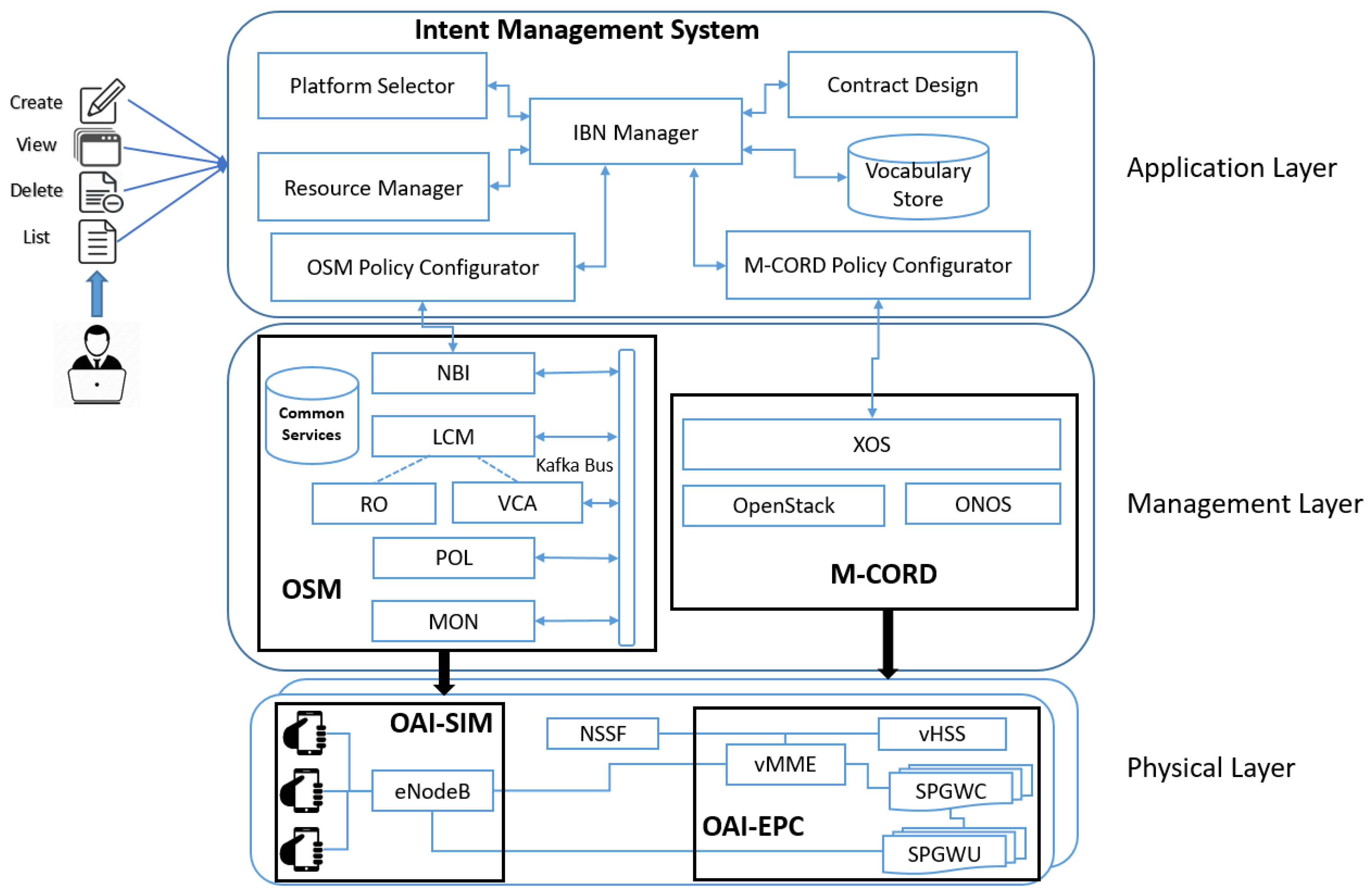
Inspired by the evolution of IBN, metadata-driven applications, and NFV in 5G networking, this paper presents the Intent Management System for M-CORD and OSM platforms to orchestrate the service for the 5G network. It is clear that for the efficient and effective operation of a sliced network, a management system is essentially needed. M-CORD and OSM platforms use dedicated configuration files and Northbound Interface (NBI) application program interface (API) for the deployment of each service, but it requires manual work and the expertise of specific 5G networks. The proposed system gets the input in the form of a user’s high-level information regarding network service and resolves this problem by translating the user’s intention into the configurations of the desired platform automatically. Then, the Intent Management System feeds these configurations into the desired platform by using their NBI API for onboarding and deployment of service on the specific platform. The proposed system takes into account the use of a three-tiered architecture composed of a Physical Layer, Management Layer, and Application Layer. The Physical Layer consists of a VNF of the mobile network as part of the OpenAirInterface solutions. The Management Layer includes the M-CORD platform of the Open Network Foundation and OSM platform of ETSI for the management of SDN, NFV, cloud, and service orchestration. On the top tier, an Application Layer exists that contains an Intent Management System tool to defines Quality of Service (QoS) for different network services in the form of contracts, which in turn get pushed to the lower tiers after translating into the valid configuration. Users can deploy specific services on one of the specific platforms supported by the proposed system at a time according to requirement.
The forthcoming paper is organized as follows:
Section 2 pours some light on the recent related topics.
Section 3 presents the details of the proposed system. In
Section 4, the proposed system is evaluated by validating the deployment of the user’s intent correctly on both domains. At last,
Section 5 concludes the paper and presents future work.
2. Related Work
NFVs and SDNs are considered as the most significant and distinguished pillars in 5G networking. These two pillars form the basis of a software-based automation model of the latest networking methods and allow the provision of network slicing [
24,
25,
26].
Just a while ago, the Zero Touch Network and Service Management (ZSM) initiative was launched by ETSI in association with various network associations and researchers. This project aims to provide software-based automation by defining standards for SDN and NFV which will be fruitful not only in deployment stages, but also in making operation methods more effective and less complex [
27]. Another notable project is the Next-Generation Platform as Service (NGPAAS), which focuses on the management of network configuration in a simplified fashion. Moreover, it also considers Service-Level Agreements (SLA) implementations [
28,
29] as well. To facilitate a user for the execution of the desired SLA, NGPAAS employs the high-level application layer. Subsequently, to accomplish the agreement, the configuration and policy are autonomously generated by the system.
Another pertinent and important concept is the Self-Organizing Network (SON), which is indeed distinguished to discuss here because multiple products have been developed using this idea [
30]. SON allows the design of networks in a unique manner that makes the designed network able to accommodate the errors itself. It also allows the network to assign the optimized resources autonomously and provides the facility to the network of scaling up or down at any time, depending upon the demand to maintain the equilibrium between resource availability and usage. The SON is abundantly linked with the access networks that monitor the real-time number of users and their generated traffic. The SON uses these statistics to maintain the balance between available resources and network capacity using optimized resources for the provision of a stable network.
Authors have reported various techniques related to the policies of schedule MANO VNF in this research [
31]. However, the approaches that have been stated in this study usually revolve around the abstract level and do not mention the precise details of various matters, such as how to accommodate individual VNF workload demands of accurate resource mapping. Another notable standard architecture for NFV service orchestration has been proposed in [
32], namely NFV MANO. Instead of considering the service requirements, MANO largely takes on resource details at the input end.
IBNM (Intent-Based Network Management) is another concept, which focuses on the simplification of the virtual switch and flow configuration of network architecture by engaging the intent frameworks. Various controllers, such as OpenDaylight [
33], ONOS [
34], and ONF [
35], have a specified intent framework provision inside the controller.
Artificial intelligence has been exploited in Experimental Network Intelligence (ENI) [
36], which facilitates the process of decision- and policy-making at the administrator end. The authors presented the theoretical perspective with the architectural details, but this article lacks the implementation details. The principal goal of ENI’s idea is to interpret customer requests in the form of commands via Intelligence Service Deployment to organize the resources in the best possible way.
In [
37], the authors propose a policy-driven network management framework. This framework takes the high-level network-wide policies in the form of a YANG data model to deploy the desired network management function. Then, network management functions monitor network elements and configure the required network service. This approach required manual work, and a deep knowledge of elements deployed for the 5G network is also required for designing the YANG model. There is a big risk of human error while designing the YANG data model. This problem can be resolved by using the Intent Management System.
A policy-based framework is discussed in [
38] to manage the 5G network based on the NFV environment. This framework also supports the subsystem involved in the deployment of a network service. However, the end-user needs to specify the resource constraints with the business rule as well. The perspective of designing this framework targets the complete network service orchestration in multiple domains. In addition to the policy interpretation, this framework also detects and resolves policy conflict. The high-level policies are discussed in this article for self-management of networks, but still required the knowledge of deployed 5G network topology. The composite decision about allocating network resources completely depends on the end-user, which can be done autonomously at the proposed framework level. Moreover, the policy definition is also not abstract because of complex business rule deployment.
The study of related work convinces us that the proposed system contains novelty in the context of end-to-end service orchestration and modeling of VNF descriptors using the web-based Intent Management System for two well-known orchestrators. All of the work presented in this section mostly focuses on a specific platform, specific policy configuration format, and intent-based network system for flow configuration in the virtual switch. Conversely, the proposed system supports not only intent-based network service orchestration, but also supports this feature for two different orchestrators. Therefore, the proposed system can convert the user’s intent into two different formats (JSON for OSM and TOSCA for M-CORD). The proposed system also provides liberty to the end-user for taking care of low-level configuration by using the Intent Management System. M-CORD and OSM provide the NBI API for service orchestration; therefore, a user-friendly Intent Management System is developed by taking the benefit of this facility for the end-user to provide the abstract layer so that the end-user can configure the desired service by providing their intention. The proposed system also provides a user-friendly graphical user interface (GUI) and simplified input for the desired network service. The proposed system is also autonomous in allocating the required resources for the deployment of the desired network service.
3. Proposed System Architecture
The following section explains the architecture of the proposed system and the operation of all modules in detail. This research article aims to extend our previous work [
39,
40] and develop an intent-based self-governing control platform for NVFs based on multiple orchestrators, as shown in
Figure 2. The main purpose of this research is to develop an autonomous system for configuration and management of the network service. The proposed system is comprised of three layers; the foremost layer is an application layer that is comprised of the Intent Management System. The Intent Management System generates the policy for the desired orchestrator and provides the interfacing with the configured orchestrators. The operators can create a contract, assign QoS parameters, select the platform, and submit their intent. The second layer is the management layer, which consists of M-CORD and the OSM orchestrator. The M-CORD platform is comprised of XOS, ONOS and OpenStack. The OSM platform consists of Service Orchestrator (SO), Resource Orchestrator (RO), and VNF Configuration and Abstraction (VCA) modules. Furthermore, XOS and SO configured the network service in the physical layer that is provided by the Intent Management System. Lastly, the concrete network functions exist at the third layer, which is a physical layer.
The functioning of all three layers is as follows: Operators provide high-level intents using the web interface of the Intent Management System, and then these intents are converted into the configurations of a selected orchestrator. Afterward, the M-CORD and OSM platform receive the configuration details through the application layer and then implement these received configurations on the physical layer. Thanks to the open source project OAI, EPC and veNodeB for the mobile network are implemented on the physical layer using the provided VNFs.
A deep understanding of the system is mandatory before further processing and testing of the proposed system. The next subsection explains the details of the working of each module their relationships with one another.
3.1. Application Layer
Seamless provisioning of service agreements is a basic requirement for a next-generation network; therefore, the application layer contains user-friendly operations support system (OSS)/business support system (BSS) applications to achieve these objectives. The proposed Intent Management System is also developed as an OSS application. The Intent Management System is a web application that consists of seven modules, including Platform Selector, Intent Manager, Contracts Design, Resource Manager, Vocabulary Store, Policy Configurator for M-CORD, and Policy Configurator for OSM, as shown in
Figure 2. This system also provides the frontend of the proposed web application, which is known as GUI, for creating, listing, updating, deleting, and detailed viewing of intent. Users can also see a generated graph of the selected architecture in the GUI, which is explained in
Section 4.2. In the following subsection, all modules of the Intent Management System are discussed in detail individually.
3.1.1. Platform Selector
The Platform Selector is the smallest module of the Intent Management System because users can select the required orchestrator for the implementation of their intents using this module. This module fetches the information of the selected orchestrator from the dropdown menu of the frontend web page and sends this information to the Intent Manager. This information is stored in the dedicated table of the Vocabulary Store, as shown in
Figure 3. This information is useful for the Intent Manager to send the user’s intent to the respective Policy Configurator because it contains the IP address of the deployed orchestrator.
3.1.2. Contract Design
In the Intent Management System, the contract represents the user’s intent. This intent consists of Single Network Slice Assistance Information (S-NSSAI), network architecture design (LTE, LTE-A, 5G, etc.), and Quality of Service (QoS) in the form of upload rate and download rate. The network architecture design is required to generate the respective policy graph because every network architecture depends on its suitable policy graph. The 3GPP body has specified the eight different slices for a massive heterogeneous network, which is denoted by the S-NSSAI parameter. In this contract, S-NSSAI represents the type of service; e.g., eMBB, URLLCs, mMTCs, etc. QoS parameters are used to assign the bandwidth to each slice. The Intent Management System provides all of this information in the GUI for the user to create contracts easily. This information is enough for Intent Management System to create the appropriate configuration for the selected network architecture. This contract design module takes these inputs from the GUI and converts simple high-level information into the required form of contract for the Policy Configurator module. Then, information of the contract is forwarded to the central Vocabulary Store.
3.1.3. Intent Manager
The Intent Manager is the core part of this system, which interacts with all other modules within the application layer as well as the management layer. It passes the generated configurations to the management layer, which is responsible for taking orders as commanded via RESTful APIs. It also validates the configuration by fetching the information from the repository that is required to be implemented. It validates the configuration by taking into account the information stored in the Policy Catalog. It communicates with different platforms registered under it via the orchestrator field mentioned in
Figure 4. Once the platform is confirmed on which the configuration needs to be applied, it posts the configurations to the relevant Policy Configurator, which will further be responsible for creating the descriptor for the selected platform.
3.1.4. Vocabulary Store
The Vocabulary Store is the database that stores all of the input taken from the GUI as well as the architectures that the registered orchestrators support in each domain. This database is designed by keeping in mind the dependency of each VNF in such a way that the generation of service graphs becomes very easy.
Figure 4 shows the design of the database. The Module Relation table helps the Intent Manager to generate the service graph for the topology to be orchestrated. The S-NSSAI table holds four basic slice configurations that allow the user to create different QoS-based (upload rate/download rate) slices, while the orchestrator option lets the user select the orchestrator that will be responsible for orchestrating and managing the VNFs within the network service generated via the contract of a user. Currently, the proposed system supports two orchestrators, i.e., OSM and M-CORD. The proposed system also supports the orchestration of the open-source LTE Advanced VNFs provided by EureCom. Overall, the Vocabulary Store helps the Intent Manager to automate the process of orchestration and management.
3.1.5. Resource Manager
This module has to allocate the resources for each policy graph. The Intent Manager sends requests to the Resource Manager for the allocation of the resources as soon as it gets the reception of the Vocabulary Store information. This allocation is done using the detailed information specified in the policy graph and Vocabulary Store. The design of the Resource Manager makes sure of the suitable allocation of the resources for each of the VNF, conditional on the number of total existing resources. This module contains information about the underline physical resources in its small database, and updates this database after allocating the resource to the request slice. The Resource Manager calculates the number of instances required to deploy the request network service, then assigns the suitable instance favor. This favor represents the quantity of RAM, CPU, and storage. If there are not enough resources available in the physical layer for the requested network slice, then it sends an error to the Intent Manager about the lack of resources. The internal block diagram of the Resource Manager is shown in
Figure 5.
3.1.6. Policy Configurator for M-CORD
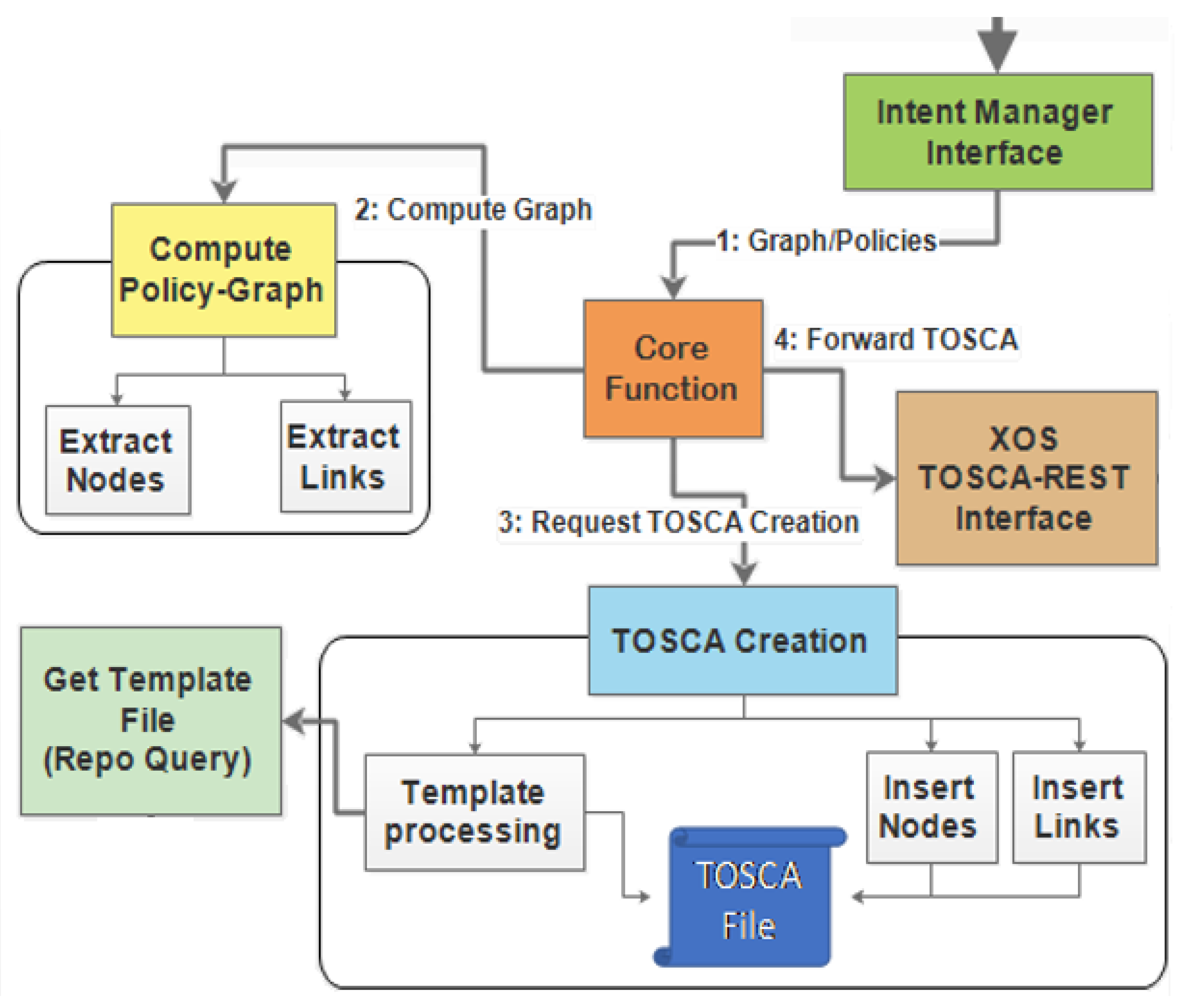
The Policy Configurator for M-CORD is a crucial and mandatory component of the intent management system because this module interprets user intent into the configuration file of M-CORD. It is the substantial module that is the backbone of the Intent Management System, as it solely acts as a bridge to deploy user intention into the M-CORD platform. The modular representation of the Policy Configurator for M-CORD is depicted in
Figure 6, which shows the internal working of the Policy Configurator for M-CORD.
It can be seen from
Figure 6 that the Intent Manager Interface module provides an interface between the Intent Management System and this Policy Configurator. This module is also responsible for delivering the policy and graphs of the Intent Management System to the Core Function module. The Core Function module is the central part of this Policy Configurator; it communicates with the rest of the modules in the following sequence.
Initially, the Core Function module sends a request to the Compute module to extract the nodes and links from the received policy graph. Afterward, the TOSCA Creation module fetches the file from the Central Data Repository and inserts the links and nodes into the file to create the TOSCA File.
Subsequently, the XOS TOSCA-REST Interface module sends the created TOSCA file to the M-CORD platform for deployment of the user intent. As M-CORD receives the TOSCA file for the deployment of network service in the underline platform, consequently, the REST Interface module of this Policy Configurator sends a complete TOSCA file using a Restful API of the M-CORD platform.
The Policy Configurator for M-CORD is simple as compared to the Policy Configurator for OSM because it has to update the existing file by replacing new information. However, the Policy Configurator for OSM creates the different descriptors dynamically on the runtime in the form of a JSON string, which has a higher complexity level than the Policy Configurator for M-CORD.
3.1.7. Policy Configurator for Open-Source MANO (OSM)
The Intent Management System is created to support multiple platforms; a dedicated Policy Configurator is required to deploy user intent into each platform. Hence, this Policy Configurator is created for the OSM platform to interpret the user intention for the OSM platform. The working of this Policy Configurator in the form of a flow chart is depicted in
Figure 7.
Unlike M-CORD, the OSM platform accepts service deployment descriptors in the form of a JSON string instead of a file. The Intent Manager Interface and the Data Collector module have similar functionality, as explained in the Policy Configurator for M-CORD. Each engine consists of multiple modules, which can be seen in
Figure 7, such as the VNF Descriptor Creation Engine, which consists of three modules, namely Basic Information, Virtual Data Unit (VDU) Information, and Connection Point, respectively. The Basic Information module is used for writing basic functionalities like names, IDs, etc. The VDU Information modules deal with information about what type of RAM or storage is required. The Connection Point module specifies the information about interfaces and port connection points. All modules execute their tasks simultaneously and produce final a JSON string that contains all configurations for describing the VNF.
The NS Descriptor Creation Engine consists of four modules, namely Basic Information, VNF Descriptor (VNFD) Information, and Connection Point, respectively, as well as Virtual Link Descriptor (VLD) Information. Similarly to the VNF Descriptor Creation Engine, the Basic Information and Connection Point modules have the same functionality in this engine. The VNFD Information module specifies the required VNF Descriptor for this NS Descriptor, and VLD specifies virtual data and management links between the specified VNFDs.
Network Slice Template (NST) Creation Module consists of three modules, namely Basic Information, VLD Information, and Network Service Descriptor (NSD) Information. This engine uses the previously created NSD and defines the network slice subnet using the NSD information module. The VLD information module specifies a VLD connection between network services.
All engines depend on each other because the output of one engine is used in the module of the proceeding engine. All engines create JSON descriptors and forward them to the onboarding module to store all descriptors in the OSM repository. Each onboarding module uses the OSM Restful API interface to send a request to the OSM, and tries a maximum of five times in case of failure. If a request fails more than five times, the OSM API interface sends a fail notification to the Internet Manager Interface, and then the rest of the procedures stop automatically. Onboarding of each module is a pre-requisite for NST instantiation because OSM uses this descriptor to instantiate the network service. At the end of the onboarding of all descriptors, this Policy Configurator sends the instantiating request to the OSM for the deployment of the required service on NFVI.
After the creation of all descriptors, this Policy Configurator module stores the information and relation of each module in the local database. This Policy Configurator keeps this information to delete the relevant descriptor and instances if it is required. As mentioned above, each descriptor depends on another descriptor; therefore, each table contains the foreign key of a dependent table. All tables contain the generic field name, description, and JSON to hold the general information of the descriptor. However, the ID fields of each table hold the auto-generated unique serial number of a new entry in the table, and the refID fields of each table hold the responded onboarding reference ID of the OSM orchestrator. The relational database design for descriptors and instances can be seen in
Figure 8.
3.2. Management Layer
In this proposed system, the management layer is used for the orchestration of the user’s intent into the underline physical layer. The management layer contains the two orchestrators, as shown in
Figure 2. The management layer receives the compatible configurations in the form of a TOSCA file for M-CORD and a JSON string for OSM, respectively. The detailed working of each orchestrator is explained in the following sections.
3.2.1. M-CORD
The Open Networking Foundation (ONF) has developed an open-source solution for a 5G wireless mobile network that is known as M-CORD. It is also known as "cord in the box" because it is a cloud-native solution and deploys in one server using an SDN, NFV, and cloud technology. Clients can interact with the provided functionality of the M-CORD orchestrator using the command line interface (CLI), GUI, and REST API. A Policy Configurator module is developed for M-CORD to manage network resources using Intent Management through the Restful Interface that is provided by XOS in M-CORD. Then, XOS translates the intent of the client into an M-CORD-compatible configuration. The XOS takes the input from the Intent Management System and deploys the received configuration on the physical layer using ONOS and an OpenStack synchronizer. Each synchronizer is accountable for the deployment of configuration on the physical layer.
3.2.2. Open-Source MANO (OSM)
ETSI has hosted a community project that is known as Open-Source Management and Orchestration (OSM). The intention of starting this project is to craft and eventually dispense a MANO stack that is critically associated with the ETSI NFV for management and orchestration of VNFs, NS, and Network Slices. The OSM also contained the functionality of configuration, maintenance, health monitoring, and performance of network resources. The OSM offers the GUI, CLI, and Restful API as a service to use all of the support functionalities at the client-side. Due to the facility of this abstraction level, the OSM avoids the exposure of unnecessary details of its constituent elements. By taking advantage of the Restful API, another Policy Configurator module is developed for the Intent Management System.
3.3. Physical Layer
It can be seen in
Figure 2 that multiple VNFs have been deployed for a mobile network in the physical layer using the open-source components of the OAI-EPC and OAI-SIM. The management layer automatically handles the configuration of the mobile network using southbound APIs of configured orchestrators. The inclusion of the virtualized Network Slice Selection Function (vNSSF) in this architecture provides the advance functionality of selecting the requested slice for network service initiated by User Equipment (UE). The physical layer continuously changes due to the provisioning of a virtualized Serving and Packet Data Network Gateway Control Plane (vSPGW-C) and virtualized Serving and Packet Data Network Gateway User Plane (vSPGW-U). The vSPGW-C and vSPGW-U are used to provide different QoS capabilities for specified services, and the management layer handles it by pushing down the required configuration on the physical layer. The detailed working of the vNSSF is explained in our previous paper [
37], and the details of OAI-SIM and OAI-EPC are explained in the forthcoming subsections.
3.3.1. OpenAirInterface-Simulator (OAI-SIM)
This research work uses an OAI-SIM for the implementation of the access network because it provides fully fabricated radio channels. The OAI-SIM is the actor who is employed to start the mobile network test. The OAI-SIM can execute the simulation of one evolvedNodeB (eNB) and up to 20 User Equipment units (UEs). Therefore, the required UEs are simulated to validate the competency of the assigned slice using vNSSF and the performance of each slice according to the provided configuration using the Intent Management System. To assign a different slice to each service, each UE is utilized to initiate the unique network service.
3.3.2. OpenAirInterface-Evolved Packet Core (OAI-EPC)
The OAI-EPC is also known as OpenAirCN because it contains the all implemented components of a mobile network, including vMME (virtualized Mobility Management Entity), vHSS (virtualized Home Subscriber Server), vSPGW-C, and vSPGW-U. The functionalities of some important modules are briefly given below:
The vMME is a bridge between the eNodeB and other components of the core network (CN). The vMME performs the required connection, updating information in the CN and access network. The core functionality of vMME is to manage the mobility of UE by tracking the movement of the UE by communicating with the vBBU.
The vHSS stores the network subscription information. The vHSS also validates the information of the UE by comparing it with the already-stored information in the database by communicating with the vMME that is sent from the eNodeB.
The vSPGW-C gathers the information of the access network from the vMME. The essential functionality of vSPGW-C is to manage the session between the core network, access network, and data network.
Data communication between the data network and access network is managed by the vSPGW-U and creates a dedicated tunnel for each slice between the UE and vSPGW-U after the establishment of the physical data unit (PDU) session.
4. System Validation
An experimental setup was created to evaluate the automation of end-to-end service orchestration using the user’s intent. The experimental setup consists of the Intent Management System, two network orchestrators (M-CORD and OSM), and NFVI (Network Function Virtualization Infrastructure) for each orchestrator as shown in
Figure 2. To validate the proposed system with the real-world use case, a complete scenario from creating the network service using the Intent Management System to reflecting the desired network service deployed on the physical layer is explained in this section, under
Section 4.2 and
Section 4.3, respectively.
4.1. Experimental Setup
The experimental setup consisted of three physical machines. The proposed web-based application Intent Management System ran on a stand-alone Windows-based machine and both orchestrators were deployed in two separate machines. OpenStack was used as an NFVI for both orchestrators.
Table 1 provides the details of the testing environment.
M-CORD provides the complete virtualized environment in one physical machine; therefore, it is known as a cord in a box (CiaB). OpenStack was also deployed in the same machine during the M-CORD deployment process. The communication medium was also established between the XOS, ONOS, and OpenStack during the deployment process.
In the case of OSM, a dedicated OpenStack was deployed explicitly to provide the NFVI for OSM in the same machine where OSM was installed. A dedicated OpenStack is required for OSM because OSM only provides service orchestration functionality and does not provide the complete virtualized cloud environment. The OSM "Getting Started" wiki page also explains all steps required for the configuration of the OpenStack Virtualized Infrastructure Manager (VIM) with OSM [
41].
The OAI provides the EPC images, which are available at the developer aweimeow repository under the name of oai-scenario. The vNSSF and veNB images were created on-site for this work. OpenStack uses these images for setting up the testing environment.
The experimental setup was comprised of three machines; therefore, all machines could communicate with each other over the unique IP addresses. Both orchestrators exposed their Restful APIs on their respective machine IP address, and the Intent Manager communicated with both orchestrators using their exposed Restful APIs. The XOS module of the M-CORD and the SO module of OSM received the generated policy graph from the Intent Management System using their Restful API. Then, both orchestrators deployed the received policy graph on the NFVI using the corresponding configured VIMs.
4.2. Testing Procedure
Figure 9 shows all contracts created for both orchestrators using the GUI of the Intent Management System. Each contract also contains the slice configured with predefined QoS values. Two contracts, WEB and VIDEO, were created for OSM and the other four contracts for M-CORD. The predefined QoS values of Slice-1 to Slice-4 are listed in
Table 2. Employing the results of the created contract, the Intent Management System also generates a graph for the selected architecture, which is shown in
Figure 10. The generated graph represents the advanced LTE network architecture, which contains the vNSSF, vMME, vHSS, vSPGW-C, vSPGW-U, and an eNB. This generated graph is used for deployment on the physical layer. The Intent Management System generates the configurations for this graph according to the selected platform automatically by using the corresponding Policy Configurator. This is the essence of the Intent Management System, because the user should not need to worry about the technical details for implementing the required service. At the management layer, the orchestrator receives the network configurations and deploys on the physical layer.
On the physical layer, six different UE configurations were particularly specified inside the OAI-SIM to evaluate the overall working of deployed network configuration using the vNSSF. The associated International Mobile Subscriber Identities (IMSIs) for each device were 208930100001111 for UE1, 208930100001112 for UE2, 208930100001113 for UE3, 208930100001124 for UE4, 208930100001125 for UE5, and 208930100001126 for UE6. Every data plane slice was autonomously enabled with its distinctive QoS by utilizing the management layer. To examine the capacity of each slice, data transmission tests were executed on every slice simultaneously.
Initially, as soon as the UE transmits the connection message towards the vMME from the eNodeB, the network registration is initiated. The message is composed of the International Mobile Subscriber Identity (IMSI). The IMSI is a combination of digits comprised of fifteen digits, which holds the Public Land Mobile Network (PLMN) with the leading five digits and Mobile Subscription Identification Number (MSIN) for the remaining 10 digits. The data plane Network Slice allocation and UE identification are achieved by using these numbers. After finishing the registration process of the UE in a network, the vMME further sends the IMSI to the vNSSF.
Then, the vNSSF queries the slice-table inside the vHSS to fetch the IP addresses of the SPGW-C and SPGW-U. These are corresponding IP addresses of the requested network service initiated by the UE. Onward from this step, the UE assigned to the data plane slice is monitored by the NSSF.
Figure 11 shows a complete sequence diagram of the slice selection procedure when the requested UE is connected to eNodeB.
Finally, the vMME forwards the IP address to the SPGW-C, which is fetched in previous processing for the session establishment of the UE connection. The IP address of the SPGW-U is also stored in a bearer-context message of the vMME that is forwarded with the details of session information to the SPGW-C. The SPGW-C selects the SPGW-U from the catalog of the user’s data plane that has been registered by utilizing the data plane slice’s IP address, which is deduced from the bearer-context message of the vMME. Finally, a PDU Session is enabled by creating a GTP-Tunnel between the UE and the chosen SPGW-U.
4.3. Results and Discussion
Both the M-CORD and OSM orchestrators receive the compatible configurations for network service in the form of TOSCA and JSON to form the Intent Management System, respectively. Then, both orchestrators deploy these configurations on the physical layer. Both orchestrators also configure the defined QoS policies into the SPGW-U during the deployment process. The OAI-EPC module applies the Linux Traffic Control (LTC) on the SPGW-U to control the throughput. This is an effective method for differentiating the data rate for each of the channels that are used to restrict the throughput of each slice on the data plane. The management layer provides these QoS values dynamically instead of using static QoS values.
To conduct performance tests, OAI-SIM is also not a very trustworthy platform. Theoretically, it can support rates of 50 to 60 Mb/s, but on the emulator, it has a throughput of around 1 Mb/s on the UE that is being emulated, which is irrespective of the connected slice. To execute the tests, the Ubuntu-supported iPerf utility was used to initiate the traffic in the VM at the facility where the OAI-SIM was configured. For well-founded tests, iPerf establishes its connection with the SPGW-U via the internet. This implies that the SPGW-U provides internet access to the physical server with a public IP address.
It is mandatory to mention that the results were produced for this paper in a completely virtual environment, and a virtual interface was created by the emulator between the SPGW-U and eNodeB as a tunnel. To produce results, the iPerf tool was used to generate the traffic on each slice individually by stating the virtual interface of the UE.
The performed test results of upload rate and download rate values for Slice 3 to Slice 6 are shown in
Figure 12. The upload rate and download rate QoS values for Slice 1 and Slice 2 are shown in
Figure 13. The data which have been depicted in these figures are a collection of the data that we regarded as authentic for the connection of UE with the data network. At the premises, a 100 Mb/s internet connection was available; therefore, it was not possible to generate traffic on all slices in parallel. To evaluate the benefit of network slicing, different combinations of slices were selected to generate traffic. The selected combination of slices should not exceed the maximum available bandwidth of the provided network architecture; e.g., Slice 1 and Slice 2, Slice 3 and Slice 4, or Slice 5 and Slice 6.
The data for both slice combinations are collected and presented in
Figure 12 and
Figure 13. The data rate sometimes went over or under the configured QoS, which can occur due to the link or with server performance issues caused as a result of executing the substantial number of VM instances on a single physical server. Moreover, another important thing to take into account is that OAI-SIM carries a greater load of processing data, and the majority of the tests do not get completed or show reckless values. However, it can be seen in both figures that the data rate for each slice lies within the configured threshold limits.
Regardless of any effect on the performance of the data plane slices, minimal resources are required to deploy the traffic control rules. The results generated in virtual environments cannot be ideal as compared to the physical environment, because in the virtual environment, generated results always show inconsistency or diminishing of the results due to repeating the experiment, which shows that the environmental performance declines with a time factor.
Section 4 highlights the proof of concept for the proposed system, which includes how the user employs this system to create the intent and verify if his created intent is reflected accordingly on the virtualized underline infrastructure.
Section 4.2 explicitly explains the step-by-step procedure of creating the intent for the desired network service, and it also specifies the mechanism of the whole testing procedure.
Section 4.3 provides evidence that the given intention of a user, with the help of the Intent Management System, is implemented accurately into the virtualized infrastructure using two different orchestrators. Additionally, several logical slices are created over a virtualized infrastructure using the proposed system. The data gathered during the testing of the deployed network service also show that the user’s intent is deployed correctly and proper resources are also assigned to each logical slice. The in-house-developed vNSSF also worked as per expectation for selecting the dedicated slice on the basis of the UE’s information. Hence, this proves that the proposed system provides full automation for end-to-end Network Service (NS) orchestration with less human interaction for two well-known orchestrators.
5. Conclusions
This research work presents an Intent Management System for network service orchestration using M-CORD and OSM platforms. Users have the freedom to control a network infrastructure using the proposed system by only specifying their intentions in the form of network architecture type and QoS value for each network slice. After receiving the input specification from the user, this platform creates the policy for the network’s configuration autonomously for the selected platform. The proposed system eliminates human error by smoothly implementing the user’s intention on the physical layer. The Intent Management System also eliminates the requirement of professional-level expertise for provisioning of the network service. Moreover, this article sheds light on the introduction of programmability to not only the control plane, but also the data plane. It is well established from the literature that although the VNF is a requirement for the selection of slice, along with it, to control the physical layer, a separate management system is also required to update and provide the VNFs. The produced results show that the proposed system has successfully implemented end-user intention on the physical layer by creating logically different resources for each network slice.
As the proposed system evolves, an innovative level of automation can be included in this Intent Management System for orchestration of a single network service by creating the network slices in multiple domains. The newly added automation modules could split the created policy graph for the configured platforms based on the available resources in those domains. To achieve auto-scaling of the data plane in real-time, a monitoring agent can be included to watch over the status of the SPGW-U traffic.

 ,
, 


