1. Introduction
Burgeoning population growth requires the construction of more infrastructure, such as buildings, roads, airports, ports, and dams, which, in turn, increases the demand for finding suitable sites or routes to meet these needs [
1]. In addition, one of the most important elements of sustainable development is safe and fast rail transport. Due to their geometric limitations, high-speed railway projects involve numerous engineering structures such as tunnels and viaducts. Therefore, many engineering structures have to be constructed in adverse geological conditions. For this reason, tunneling in weak ground conditions represents one of the most common tunneling challenges. Tunneling through units containing clay minerals carrying the swelling potential has specific short-term and long-term problems. In tunnels excavated through cohesionless sand units, significant problems are encountered both during the excavation and application of tunnel support systems. If the tunnels with a low overburden are excavated beneath residential areas, possible deformations and failures during excavation works directly affect the infrastructure and buildings located in the close vicinity. Furthermore, for inner-city underground transportation (metro) systems—which have a shallow overhead cover thickness—carrying out excavations with tunnel boring machine (TBM) seems to be the most appropriate method. The most essential factor is choosing the most suitable TBM considering the ground conditions. The employment of the earth pressure balance (EBP) type of TBM, which balances the pressure on the tunnel face, is usually preferred for the excavations. However, in large transportation tunnels such as highways or railways, if the length of the tunnel is short, tunnels are excavated using classical mechanical excavation (i.e., the drill and blast method). In such cases, due to the large cross-section of the tunnel, the tunnel is generally divided into the top heading, bench, and invert. The priority is to ensure the stability of the tunnel face and tunnel ceiling during excavation works. In these cases, the tunnel ceiling is secured by the umbrella method and the tunnel face is stabilized by shotcrete and fiber rock bolts. In such ground conditions, the very short self-standing time of the opening requires the tunnel support systems to be stabilized immediately. Terzaghi [
2] and Bienawiaski [
3] stated that the unsupported stand up time in soils is apparently very short.
When instability problems in weak soils are examined, many factors are found to be influential. Some of these are the groundwater conditions, excavation method, the tunnel support systems, and the mechanical properties of the soil units [
4]. Lunardi [
5] summarized that three main cases are observed on the tunnel face. First, if the tunnel is being excavated through a rock unit, stable conditions are encountered at the tunnel face. However, if the tunnel excavation takes places inside clay units, plastic deformation will occur on and around the tunnel face, and in turn sliding may occur on the tunnel face in a short time. Moreover, in the third case, when carrying out excavations inside a cohesionless sand unit, flow and slippage will occur at the tunnel face.
Since the New Austrian tunneling method (NATM) was proposed by Pacher and Rabcewicz [
6,
7,
8], the behavior of highly squeezing and flowing grounds has been studied, and further revisions have been made on this phenomenon in the course of time. The NATM method started to be implemented with the development of shotcrete technology, and it has been also been applied on weak soils. In large-scale tunnels excavated inside squeezing and flowing soils, the NATM has formed the basis of today’s tunneling by dividing the excavation process into stages.
The main purpose of the present study is to describe the mechanisms of the failures that took place at the portal location and in the middle of the tunnel excavated in weak ground conditions. For the purpose of the study, the relationship between portal excavation and tunnel excavation stability is important and is explained. All the excavation stages are analyzed and the results are discussed. Consequently, the tunnel case presented in the study is interesting for the tunnel community, provides serious experience for future tunnel works, and has scientific merit.
2. Background
In general, there are two approaches for building support systems for tunnels located in swelling and squeezing ground conditions. The first is a passive approach, allowing deformation after the excavation, whereas the other is an active approach that does not allow any deformation after finishing the excavation works. However, the support type in low overburden urban tunnels is the active approach, which does not allow deformation after tunnel excavation.
Tunnel support systems must be applied without any loss of time due to potential deformations in tunnels, which are excavated through cohesive soils and clayey units, and in which immediate reinforcement is necessary. This is because deformations grow rapidly in such soils, and they can lead to collapse.
Tunnels that are excavated through weak ground conditions with a shallow overburden thickness have a critical importance in tunneling studies. For these tunnels, the most crucial factor is to secure the stability of the tunnel face and tunnel crown. Moreover, the occurrence of potential collapses at the ceiling and face of the tunnel will result in sinkholes on the ground surface. Especially for these tunnels excavated through low cohesive or cohesionless soil units, the stability of the tunnel face and ceiling must be consistently guaranteed.
Completing tunnel excavations within a single stage is always preferred for the welfare of the tunnel stability. However, in cases of a large-diameter tunnel, excavations are split into top heading, bench, and invert sections. To secure the stability of tunnel support systems applied to weak ground conditions, likewise for this divided tunneling system, it is compulsory to close the ring and complete the excavations of top heading, bench and invert sections as quickly as possible.
Furthermore, for inner-city tunneling systems, which will be excavated through cohesionless soils with a shallow overburden cover thickness, completing excavations in a single stage and carrying out excavations with EBP type TBM, is preferred. The face stability of tunnels drilled with EBP type TBM is achieved through the application of pressurized air on the tunnel face. In contrast, for the NATM method, the stability of the face and the ceiling is provided by the application of tunnel support systems (shotcrete and rock bolts) on the tunnel face and the installation of forepoling (umbrella) on the tunnel crown.
In a study conducted by Atzl [
9], the problems and suggested solutions for large-diameter inner city tunnels were evaluated. According to the study of Atzl [
9], it was stated that NATM is to be applied for weak ground conditions and for inner city tunnels in central Europe. In this study, it is emphasized that ground conditions and boundary conditions should be clearly defined for successful design and construction. As a result, it was stated that there are many difficulties in the weak ground tunneling applied in city centers, and that there are no general solution standards. It is also emphasized that each tunnel requires unique ground research and innovative design solutions [
9].
Diameters of 2- or 3-lane highway tunnels and two-track railway tunnels generally range between 10 to 16 m, and the majority of such tunnels are usually excavated through weak soils. In such tunnels, if the rock mass strength to in situ stress ratio is less than 0.2, stability problems are likely to be encountered in the tunnel supports and tunnel faces [
10]. In the study conducted by Hoek [
10], the Yacambu-Oubior tunnel, which was constructed in Venezuela for a water transmission with a diameter of 5.5 m, a length of 25 km and having lasted for more than 32 years, was examined. This tunnel, having a maximum overburden thickness of 1270 m, was excavated through graphitic schist and is notable for passing through the most difficult ground conditions in the world. Tunnel excavations initiated at the beginning of 1975; later, the TBM was completely stuck inside the tunnel, and the tunnel was completely blocked. Later, excavation and support works had been implemented in the conventional method before the tunnel support system was revised according to 30 cm deformation slots in between the steel ribs. In the 10 m diameter tunnel excavated in India within the scope of Nathpa Jhakri Hydroelectric Power Plant Project, large deformations occurred beneath the 300 m overburden thickness through the fault zone transition. This section was successfully re-excavated using the forepoling method [
11].
During the fault zone transition on the 16-m-diameter Mucha highway tunnel in Taiwan, deformations occurred up to 1.2 m inside the tunnel, and this section of the tunnel was re-profiled. Long sized grouting cable anchors were used for support. The tunnel excavation was completed by means of very heavy fortification. Later on, inner-coating concrete was implemented as soon as possible [
10].
The Bolu Tunnel, which is located on the İstanbul–Ankara Highway, consists of two tunnels, each with three lanes. Excavation works were initiated at the Asarsuyu (Istanbul) side on 16 June 1993 and at the Elmalık (Ankara) side on 24 June 1994. The excavation of the tunnel was completed in 2006, and it was opened to traffic in 2007. Dalgic [
12] examined the squeezing conditions in the Bolu Tunnels during the excavation of the fault zone. In the fault zones encountered during the tunnel excavations, deformations up to 1.5 m in size occurred. In order to prevent an entire collapse inside the tunnel, these zones were filled with the embankment material. Afterwards, this section of the tunnel was excavated, and support systems were implemented according the bench-pilot tunnel method [
13]. Various solutions were considered for the section that was filled following the collapse. Due to the complete collapse of the tunnel, it was seen to be almost impossible to ensure the stability of the tunnel by carrying out excavation procedures with respect to conventional tunneling methods. Eventually, the most appropriate project design for crossing this fault zone was the application of the bench pilot tunnel method. A series of 5-m-diameter pilot tunnel excavations were made in the bench of these sections, and they were filled with iron reinforcement and concrete. The top heading section comprises 70 cm shotcrete. The fault zone was passed without problems when using the bench pilot tunnel method [
14].
The Zhegushan, Laodongshan, Minyazi, Xiangshan, Yingfeng, and Yezhping tunnels in China represent similar problematic cases [
15]. Many similar problems were encountered in these tunnels both during and following the excavation. During the excavations, many fault zones, weak soils, and shear zones were identified. While excavating these critical sections, large deformations were encountered, failures occurred in the support systems, and the deformation rates in the Xiangshan tunnel archetypally reached up to 5.4 cm per day. High-risk scenarios in these sections were successfully overcome by modifying the tunnel support systems appropriately [
15].
In the study conducted by Goricki et al. [
16], selection criteria of the tunnel support system at fault transition zones were evaluated. As a result, five main items are proposed for the success of the design [
16]. These are (i) revealing the practical geological and geomechanical conditions for on-going construction, (ii) producing an applicable tunnel design, (iii) assigning an appropriate monitoring program, (iv) determining a suitable excavation and support system that is adaptable depending upon the progress of excavation, and (v) estimating the objective design criteria for the determination of an excavation and support system. In a study conducted by Sulem and Manh [
17], the squeezing problem inside the St-Martin-la Porte gallery opened under the Lyon–Turin Railway Project was investigated. The total length of the tunnel was 2329 m and the cross-sectional area ranged from 77 m
2 to 125 m
2. During the tunnel excavations, no problem was encountered from Jurassic carbonated rocks units and Triassic dolomites. However, very severe squeezing problems occurred in the schist units. The convergences at the lateral side walls exceeded 1.0 m and the daily deformation rate was in cm scale. This section of the tunnel was successfully completed by “Highly Deformable Concrete Elements” developed by Bonini and Barla [
18].
In a study conducted by Özsan and Karpuz [
19], the fortification design of the 5-m-diameter subway tunnels of the Ankara underground system that were passing through weak ground conditions and weathered dacite units was examined. Numerical analyses and theoretical-empirical assessments were performed within the scope of this study. No problem was encountered in cases where rock mass strength was greater than tangential stress for tunnels excavated through dacite units. However, studies conducted into the weak zones showed that deformations occurred because the ratio of rock mass strength to the in-situ stresses was relatively small. Besides, it was revealed by the results of the numerical analysis that the diameter of plastic zone reached up to 9.6 m.
According to Hoek [
20], many problems of heavy passive fortifications have been encountered in tunnels that were excavated through weak rocks. Additionally, regarding that study—H and/or I-type of steel ribs were being ruptured under high pressures when they were unable to carry the loads. It is stated that deformations will occur on the shotcrete as a result of the external forces until the required strength is reached. In order to avoid these two situations, TH-type ribs are proposed rather than I- or H-type steel ribs. As a result, no deformation has emerged due to the sliding of the ribs over one another. Moreover, it is indicated that, there is the placement of deformation slots between steel ribs [
21], the preliminary deformations taking place until shotcrete reaches an adequate strength would prevent any damage to the shotcrete system. Finally, it is underlined that there should be forepoling or umbrella application in the ceiling section for squeezing ground conditions.
As can be seen from some previously published studies, each tunnel case is almost unique, and each tunnel problem needs a special solution. However, every tunnel problem has features that can contribute to future studies.
5. Determination of Tunnel Support Systems
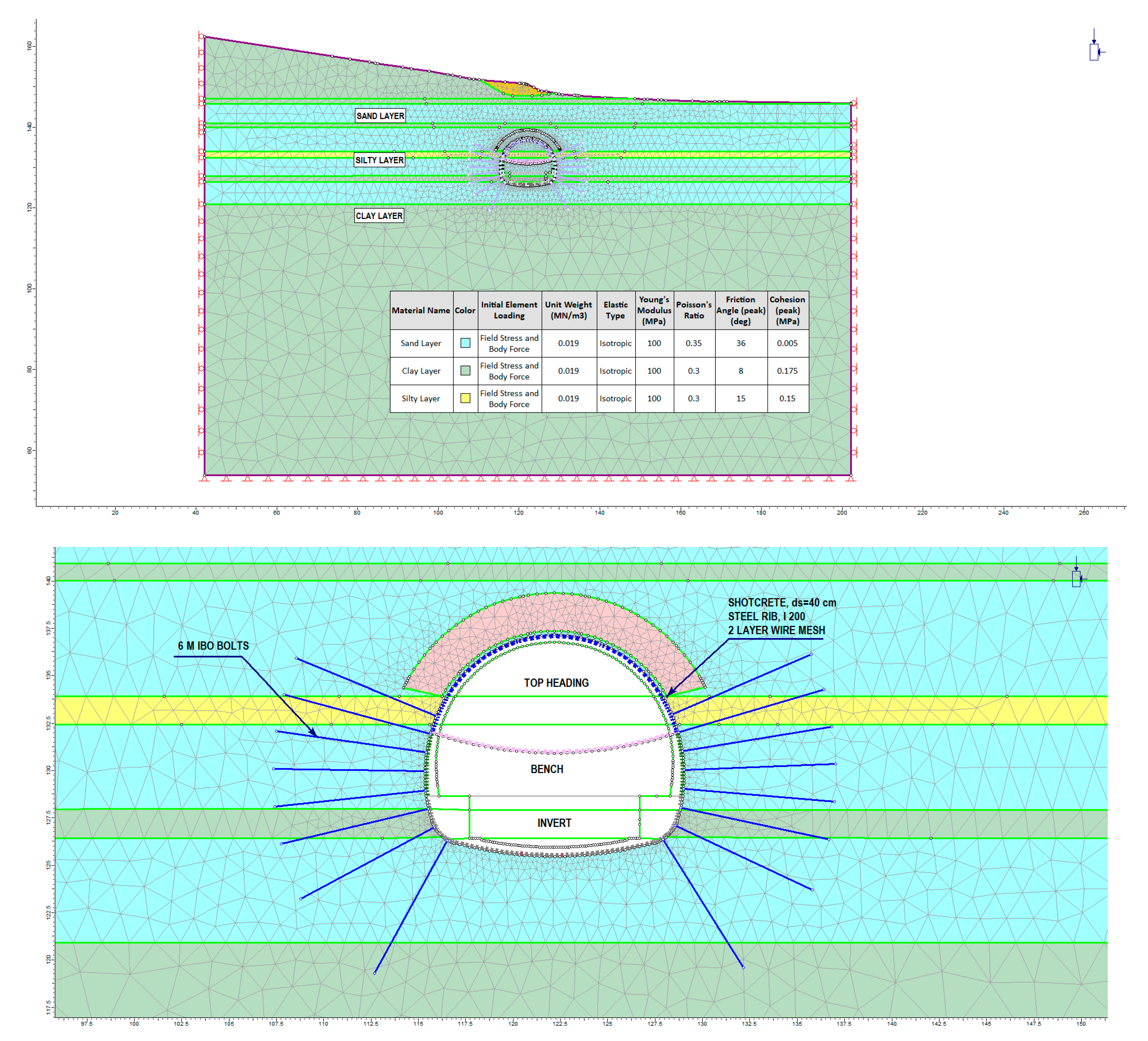
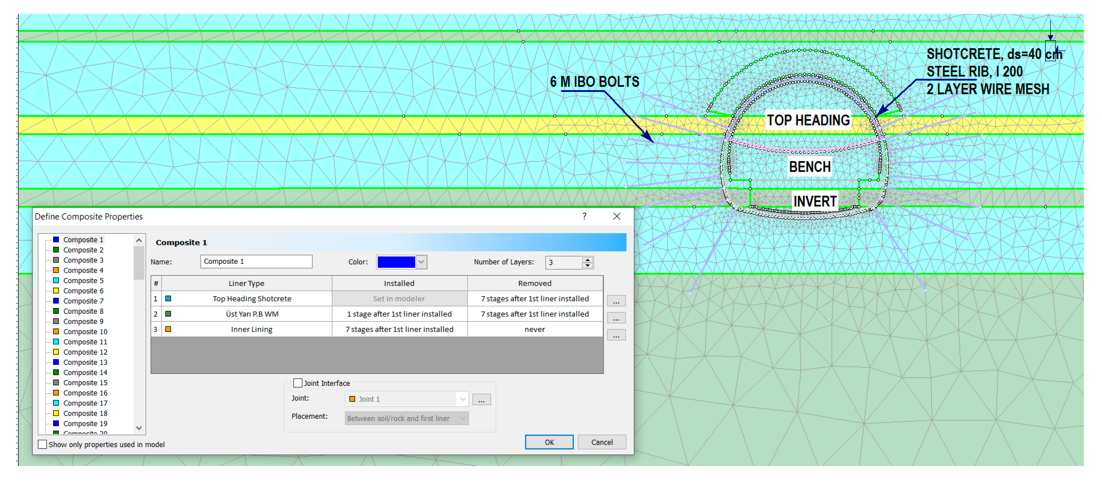
Because of the encountered problems at the portal sections and in the interior-tunnel, the tunnel support systems were revised substantially. The T3 tunnel was designed according to NATM principles. Numerical analyses were performed using the Phase2 v8.0 (Version 8.0) program. Phase2D is a two-dimensional elasto-plastic finite element stress analysis program for designing tunnels, underground openings or surface excavation and their support systems, developed at the University of Toronto to model rock masses and their behavior supported by these masses. In the program, underground excavation can be modeled gradually, and rock bolt, steel lining, wire mesh steel and sprayed concrete can be supported. Furthermore, load splitting and material softening can be applied between excavation stages [
30]. The models used for phase analyses are presented in
Figure 11. The modelling stages are presented in
Table 5.
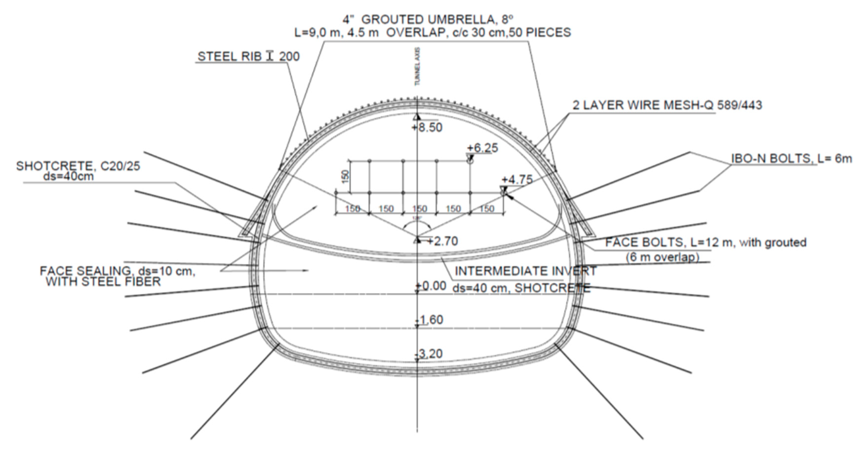
Since the tunnel was generally excavated through sand, clay, and silt, stability problems were encountered at the tunnel ceiling and tunnel face. Therefore, while determining support systems and performing related calculations of stability through the tunnel, the structure was secured by the installation of a 101.6 mm diameter forepoling (umbrella) at the tunnel crown, and the application of shotcrete on the tunnel face along with the installation of rock bolts. The main problem with these types of tunnels—excavated through sand, clay, and silt—is the occurrence of collapse due to the structure’s inability to overcome unstable conditions in the tunnels. Moreover, for these types of soils, a self-drilled bolt must be installed during the application of support systems, as consolidation grouting around the tunnel periphery can be implemented using self-drilled bolts. Tunnel stability can be achieved by creating a protective zone around the tunnel using high pressurized grouting, with bolts installed every 1 m around the tunnel. Since the T3 tunnel is situated under a residential area with a maximum cover thickness of 20 m, it is of crucial importance. Consequently, the correct implementation of all support system components becomes mandatory for the construction phase of the T3 tunnel. The k-value used in the analyses was taken as 0.5, and the Poisson ratio was assumed to be 0.35.
During the modeling stages, the load carried by the tunnel throughout the excavation works does not comprise the impact of the entire overburden thickness. Correspondingly, the design of a support system with such a principle creates the need for a large lining thickness around the tunnel, together with many rock bolt applications. However, this situation would not be appropriate in terms of the economic and engineering perspective [
31]. When the ground reaction curve is examined, the tunnel is found to reach its most optimal support system by allowing considerable deformations around it. Therefore, the necessary geotechnical monitoring tasks should be conducted during the construction stage, and by the interpretation of the results obtained from the measurements. Any required revision can be made on the support systems.
Excavation stages and load distribution during the modelling phase are given in
Table 5.
Table 6 represents the distances between the top heading-bench and bench-invert.
5.1. Results of Numerical Analyses for Km:57+400
Analyses were interpreted for two cases, namely the short-term and long-term. After estimating the first eight stages, by adding inner lining and basement concrete to the model in stage 9 and adapting the material parameters to the drained case, the model was run.
• Short-term Analyses
When the results were examined, the vertical deformations developing around the tunnel were found to be 8.2 cm at the tunnel ceiling, 8.2 cm and 6.8 cm at the left and right shoulders of the tunnel, respectively; 4.0 cm and 3.0 cm at the left and right bench of the tunnel, respectively, and 1.60 cm at the tunnel basement (
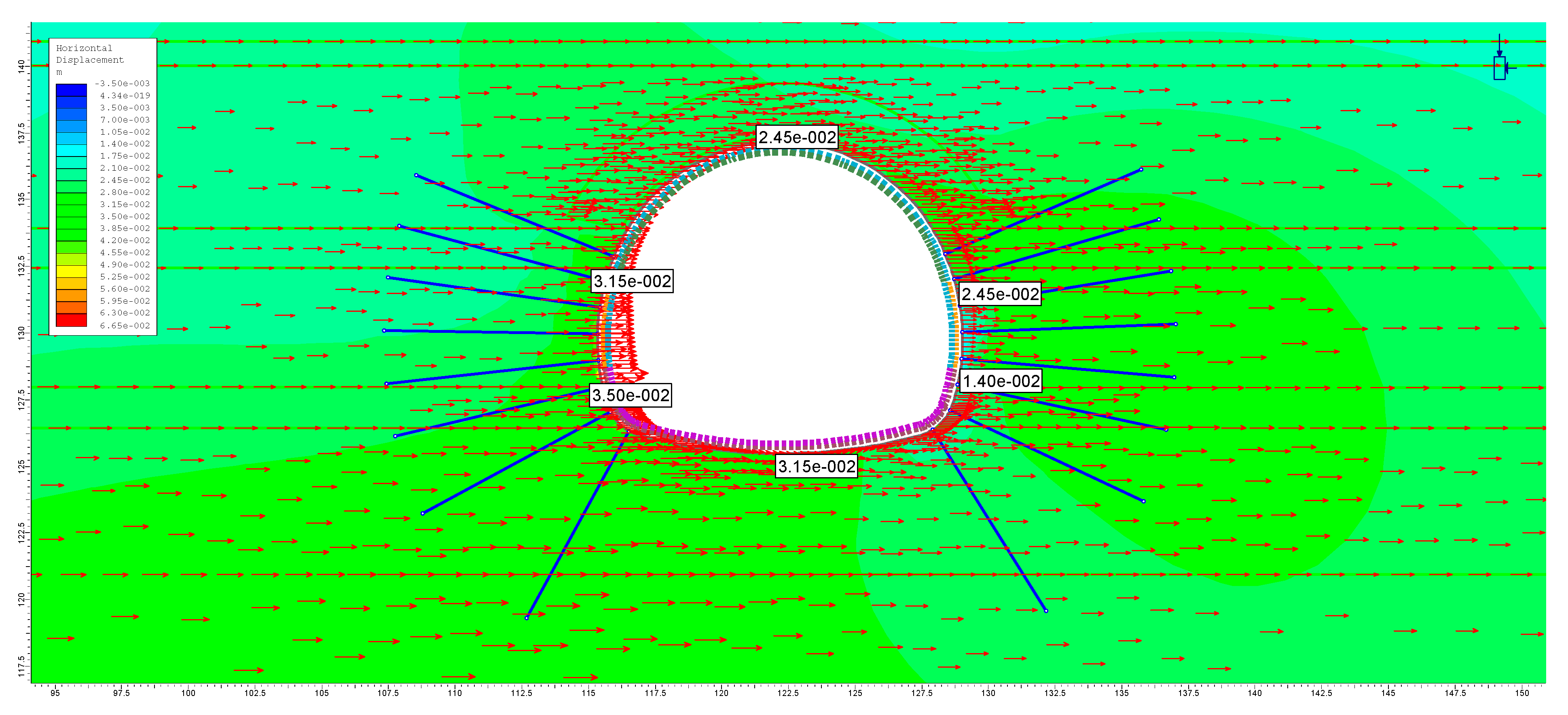
Figure 12). The horizontal deformations developing around the tunnel were found to be 2.45 cm at the tunnel ceiling, 3.15 cm and 2.45 cm at the left and right shoulders of the tunnel, respectively; 3.50 cm and 1.40 cm at the left and right bench of the tunnel, respectively, and 3.15 cm at the tunnel basement (
Figure 13).
The maximum cross-sectional effect values for shotcrete lining are 0.49 MN (
Figure 14) and a moment of 0.07 MN (
Figure 15). The analyses below indicate that proposed wire mesh, steel lining and shotcrete design are adequate for carrying the forces on the tunnel (
Figure 16).
• Long-term Analyses for Inner Lining
In order to see the changes in the inner lining in the long-term and to see the cross-sectional effects of the earthquake load in the shallow tunnel, the analyses were carried out for the last stage. In the analysis, long-term (drainage parameters) parameters were passed, the outer lining (bolt, steel shoring, shotcrete) removed from the model and the inner lining installed (
Figure 17 and
Figure 18). At this stage, the model was entered as a 0.2 g horizontal acceleration value and 0.66g vertical acceleration value.
When the results are examined, the vertical deformations developing around the tunnel were found to be 3.0 cm at the tunnel ceiling, 6.0 cm and 3.0 cm at the left and right shoulders of the tunnel, respectively, and 3.0 cm at the tunnel basement (
Figure 19). The horizontal deformations developing around the tunnel were found to be 19.5 cm at the tunnel ceiling, 21.0 cm and 18.0 cm at the left and right shoulders of the tunnel, respectively; 19.5 cm and 16.5 cm at the left and right bench of the tunnel, respectively, and 19.5 cm at the tunnel basement (
Figure 20).
The main reason for the large deformation under the earthquake effects is that the tunnel was excavated in soil, as well as the low overburden.
The cross-sectional effects of the inner lining obtained with an axial force is 1.120 MN (
Figure 21) and the moment is 0.340 MN (
Figure 22). There are large differences between the short- and long-term values in the cross-sectional effects. This showed that the inner lining concrete should be made with reinforcement.
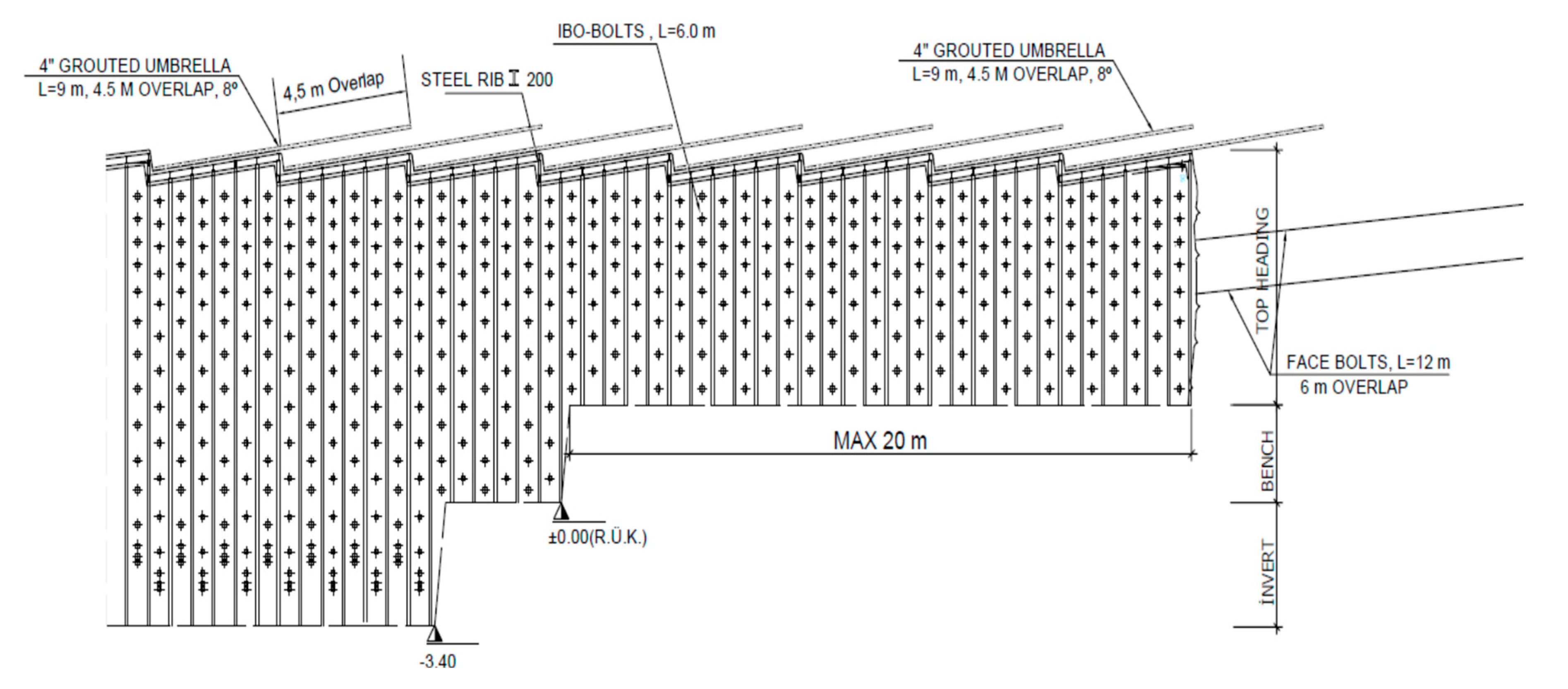
Details of support systems proposed for flowing ground conditions are provided in
Figure 23 and
Figure 24.
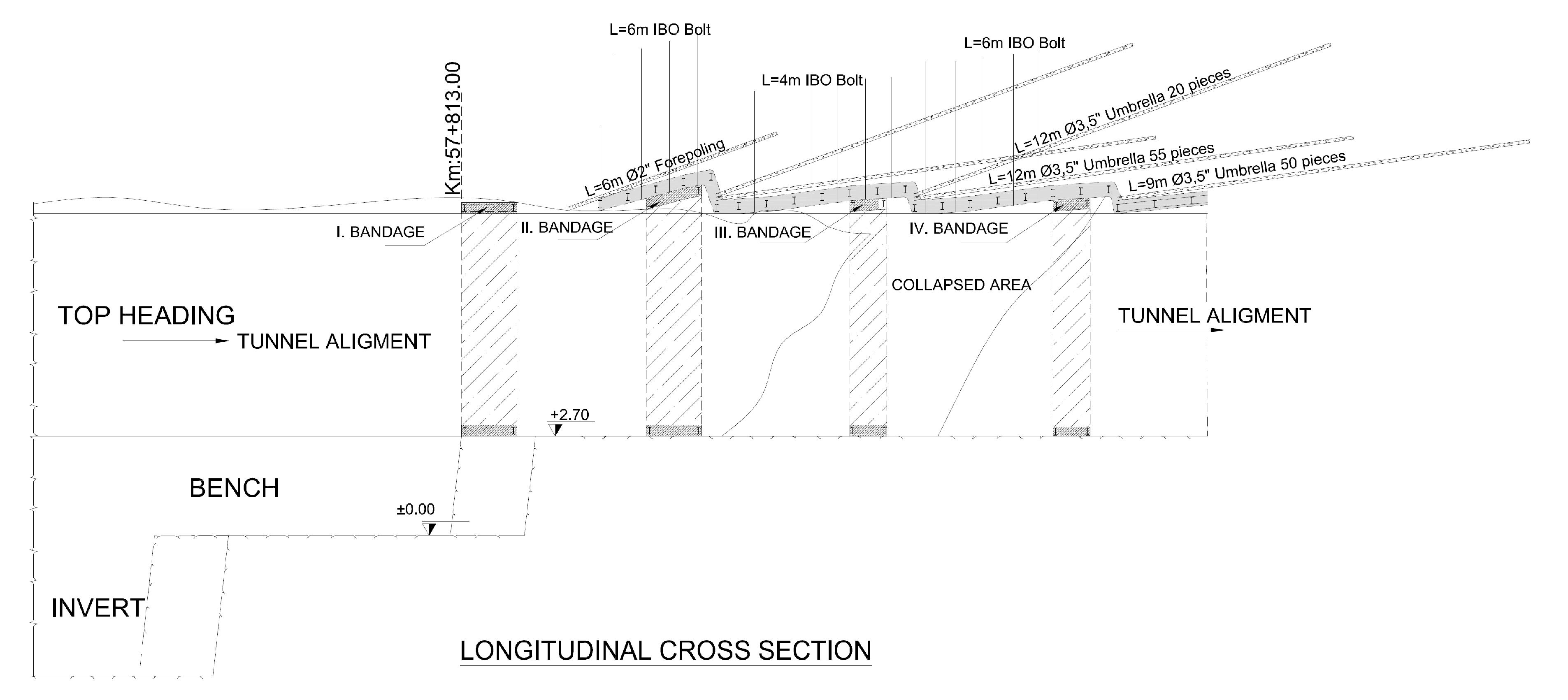
5.2. Collapse at Km:57+800
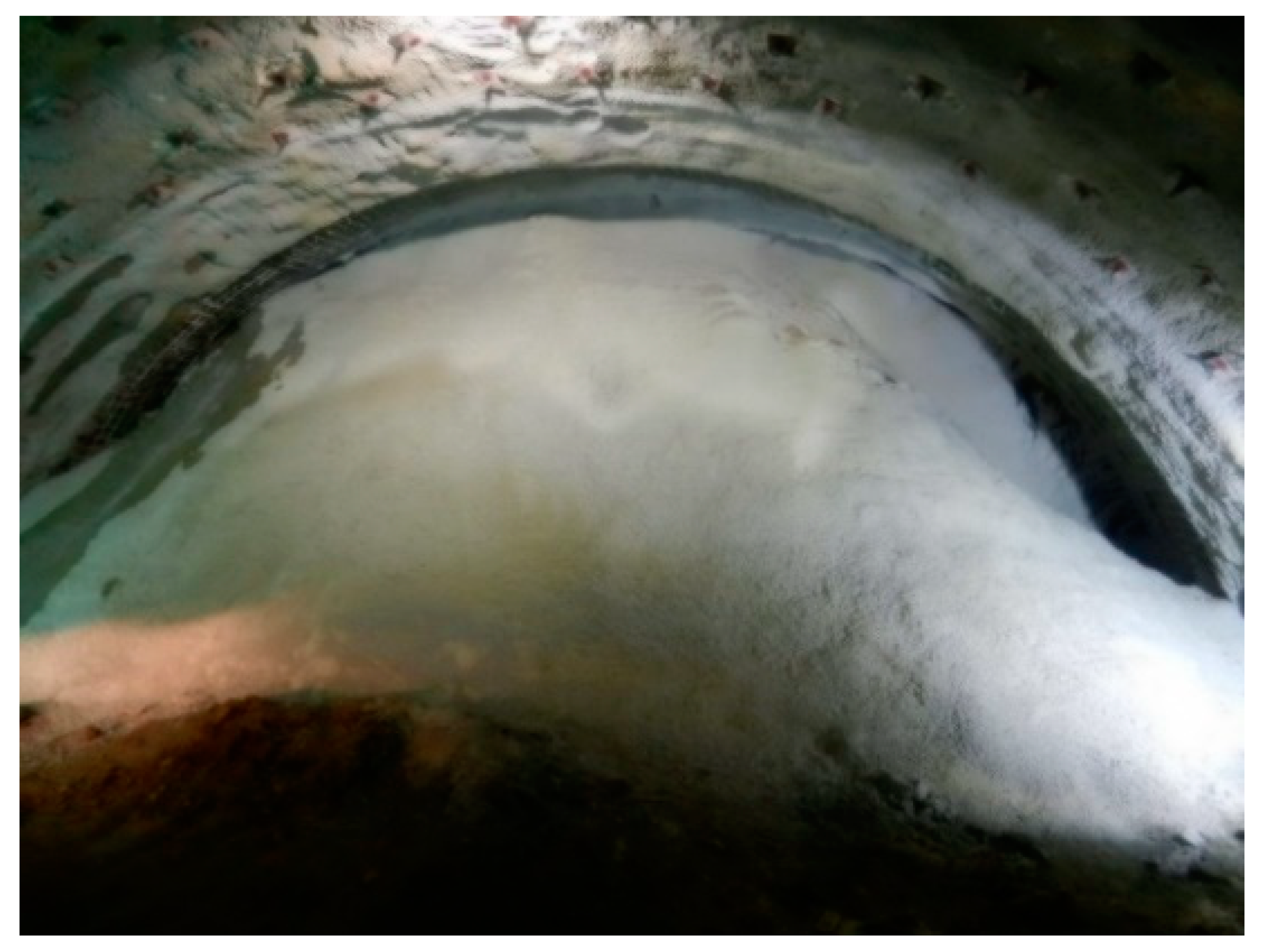
During the tunnel excavation works at Km:57+800, a collapse occurred due to the material flow in the tunnel face. Consequently, the excavation works were suspended. The face collapse is shown in
Figure 25. To pass this section of the tunnel, necessary revisions were made in the project works.
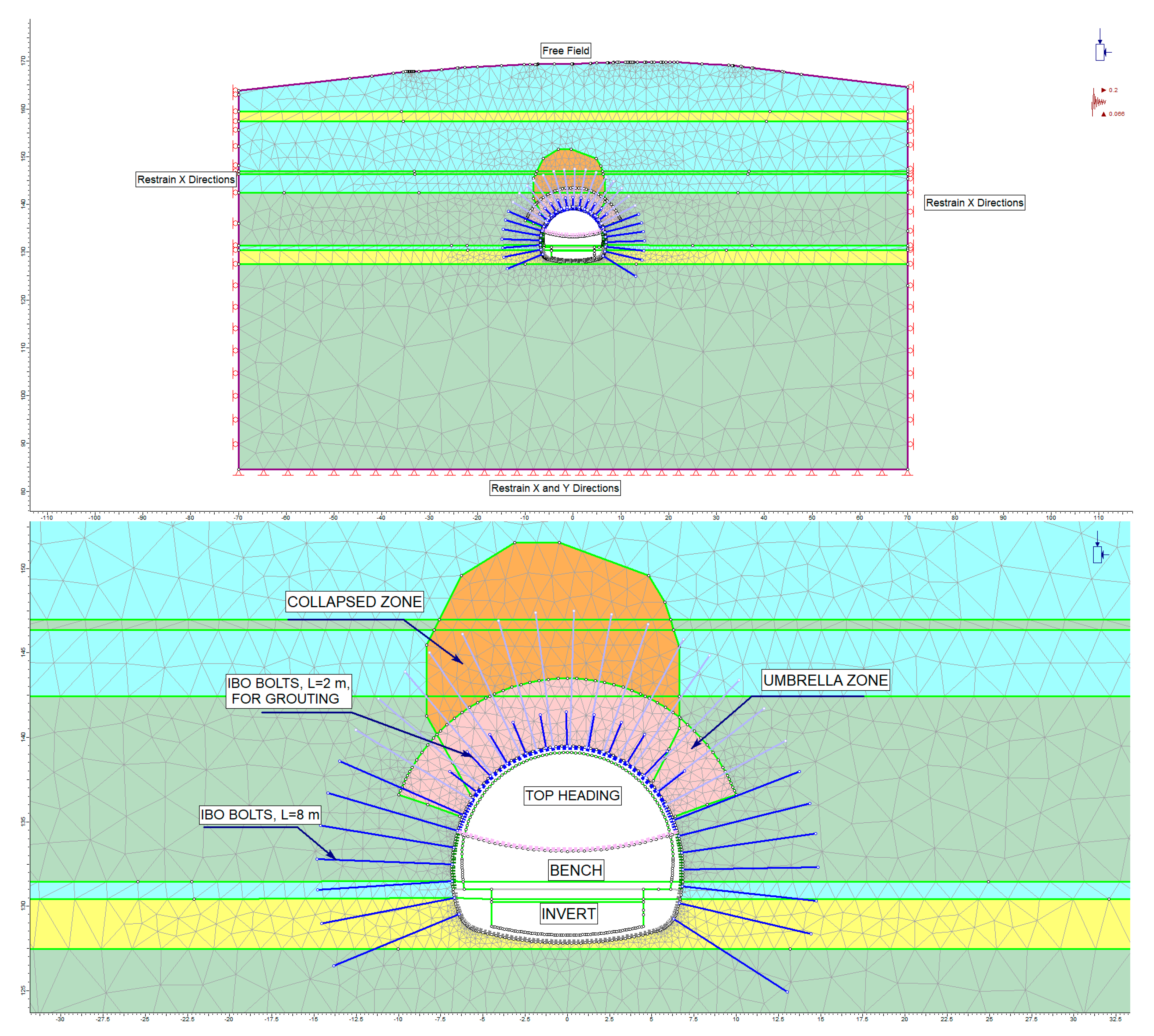
Table 7 shows the modeling stages of the collapse, and
Figure 26 illustrates the model created by the Phase2d v8.0 program produced by RocScience [
30].
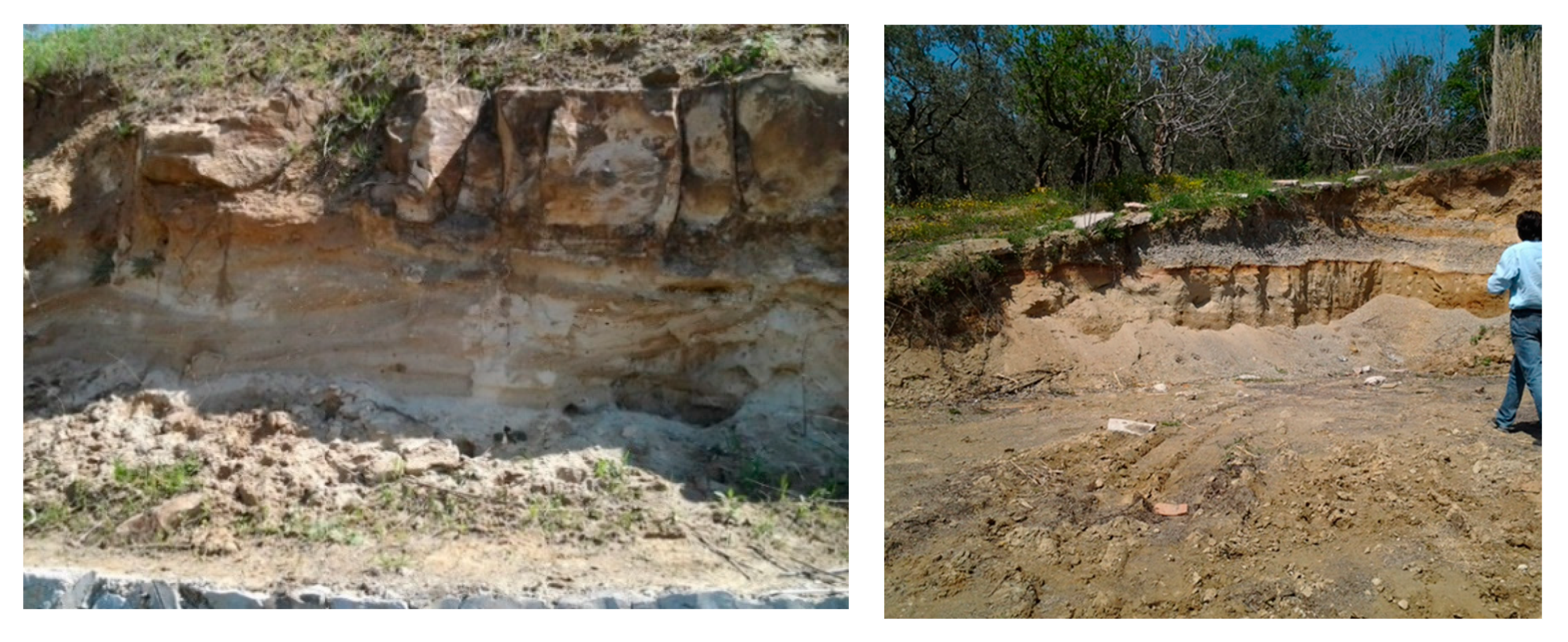
The overburden height in this section of the tunnel is 30 m and the ground profile is sand, silty clay, and clay. The tunnel was excavated mostly within the clay unit and opened in the squeezing and flowing ground conditions (
Figure 27). After the completion of the tunnel supports in the top heading, a sudden collapse occurred and the tunnel completely closed. The main reason for the collapse of this part of the tunnel was the occurrence of cohesionless sand in the tunnel ceiling section, as well as insufficient forepoling with a diameter of 2”.
To pass this section of the tunnel, revisions were made in the project works.
Table 7 summarizes the stages of the modeling.
After the collapse (
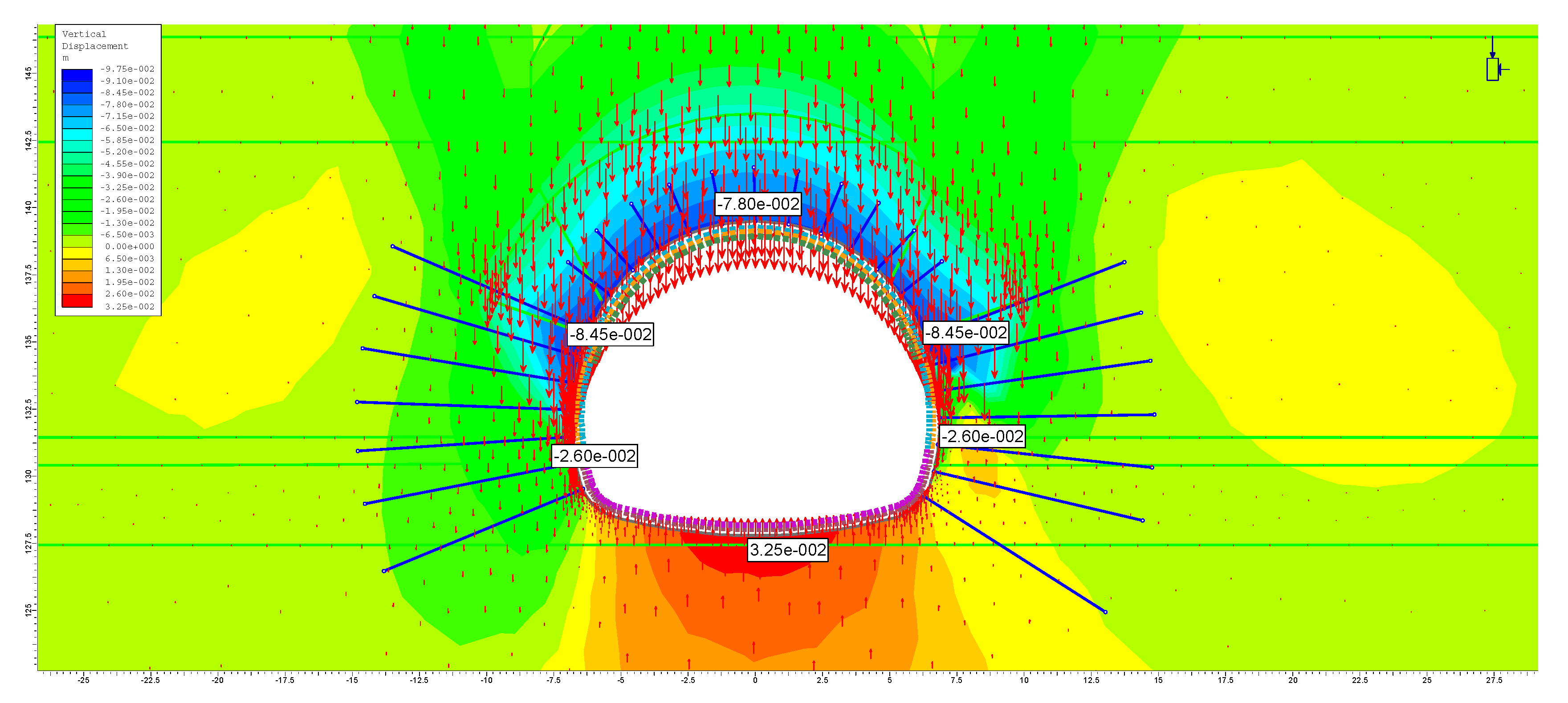
Figure 28), analyses were carried out as described above, and in the analyses, the top heading of the tunnel face was first filled to secure the tunnel’s stability, such that the displacements in the model were set to zero. Afterwards, umbrellas were installed to the ceiling section, together with the grouting application, and subsequently the excavation phase was continued.
When the results are examined, the vertical deformations developing around the tunnel can be observed as being 7.80 cm at the tunnel ceiling, 8.45 cm at the left and right shoulders of the tunnel, 2.60 cm at the left and right bench of the tunnel, and 3.25 cm at the tunnel basement (
Figure 29).
6. Conclusions
In the present study, the mechanism of portal and tunnel failures constructed in weak ground conditions is investigated and new support systems are proposed. The proposed support systems are analyzed extensively and the results are discussed. The results and conclusions obtained from the study are summarized below.
The main reason for the failure at the entrance portal of the T3 tunnel is the interaction between the problems experienced inside the tunnel and those at the portal slopes. In tunnels that are excavated through sandy and clayey units like the T3 tunnel, the priority is to ensure the stability of the tunnel face and tunnel ceiling during the excavation works. Throughout the excavation stage, drift and slippage at both the tunnel face and the tunnel ceiling are possible, adversely affecting the entire tunnel support system. Furthermore, when such tunnels are excavated beneath residential areas, where the overburden thickness is low, possible collapses inside the tunnel will result in sinkholes on the ground surface. Hence, forepoling applications through the tunnel ceiling and the installation of rock bolts at the tunnel face are the most important features of all support system implementations.
The T3 tunnel is situated under a residential area with a maximum cover thickness of 30 m; therefore, it is of critical importance. Consequently, the implementation of all support system components becomes mandatory for the construction phase of the T3 tunnel.
The following conclusions were obtained for weak ground tunneling considering the experiences gained from the T3 tunnel project:
The most important factor in tunnels excavated through weak ground conditions is the stability of the tunnel ceiling and the tunnel face.
After each tunnel face excavation, air contact must be eliminated by the application of the shotcrete method on the tunnel face. Moreover, the stability of the tunnel face must be ensured by installing rock bolts.
For the stability of the tunnel ceiling, the forepoling method should be implemented with an overlap distance of half of an umbrella length.
In an inner-city tunnel planned to be excavated through weak ground conditions under a shallow overburden thickness, a rigid application of tunnel support systems must be applied.
The inner lining of the tunnel should be equipped with steel reinforcements to prevent deformations that may occur in the long-term, and to resist the earthquake load.
In cohesionless sandy and silty units, a self-drilling rock bolt should be used. Drilled hole diameters for rock bolts should be at least three times larger than the bolt diameter.
By applying high pressurized grouting with self-drilling bolts, a protective zone around the tunnel will be formed, and in turn it will contribute to provide arching around the tunnel.
Tunnel excavation should not be initiated without securing the portal stability. While excavations are taking place under the portal slopes, round lengths must not exceed 50 cm. Furthermore, the occurrence of deformations inside the tunnel should not be allowed.
In the collapse zones, to fill the possible voids at the tunnel ceiling, double-layer forepolings should be applied, and one layer should have the adequate inclination for reaching the collapse zone. Umbrellas in the collapse zone must be installed at least every 12 m with an overlap of 6 m during the progress.
The proposed support systems and excavation stages were performed successfully, and the T3 tunnel was completed without a failure after the revision of the support systems and excavation stages. The support system proposed for the T3 tunnel is applicable for tunnels being excavated in similar ground conditions, however geological and geotechnical conditions must always be investigated carefully. Consequently, the study presents the experiences gained from the difficult ground conditions of a particular tunnel excavation.


