Review

Aerogel-Based Plasters and Energy Efficiency of Historic Buildings. Literature Review and Guidelines for Manufacturing Specimens Destined for Thermal Tests

by
Davide Del Curto
and
Valentina Cinieri
*
Department of Architecture and Urban Studies, Politecnico di Milano, 20133 Milano, Italy
*
Author to whom correspondence should be addressed.
Sustainability 2020, 12(22), 9457; https://doi.org/10.3390/su12229457
Submission received: 29 September 2020 / Revised: 7 November 2020 / Accepted: 8 November 2020 / Published: 13 November 2020
(This article belongs to the Special Issue Preventive Conservation and Energy Efficiency of Heritage Buildings)

Abstract

:
This paper presents a literature review about aerogel-based products for building, focusing on the plasters used within the architectural restoration sector. Aerogel has entered the construction field in the last two decades as a component of many insulation products, due to its high thermal performance. Aerogel-based plasters allow the matching of high thermal performance and limited thickness. This makes them suitable when retrofitting an existing building and also when restoring a heritage building. We analyze the results of recent research, focusing on the most commonly used methods for assessing the thermal performances and durability of aerogel-based plasters. As a result of this review, we propose a guideline for manufacturing samples destined for laboratory tests.

1. Introduction

Research on silica-aerogel insulating materials is part of the broader issue of environmental sustainability. Energy demand has increased in the world for the last three decades, due to industrial development and population growth. Despite reserves being limited, non-renewable resources still dominate the energy market [1]. The construction sector is responsible for 42% of the total energy consumed [2], and for the use of 50% of the natural resources extracted from the earth’s crust [3].
Following this path, the Life Cycle Assessment (LCA) method was developed for industrial production, which was based on the mantra “from cradle to grave”. LCA considers the entire life cycle of a product, from the extraction of raw materials, until final disposal [4,5]. Life Cycle Thinking means moving from processes considering energy efficiency and environmental sustainability during lifetime only, by using high-performance insulation products [6,7], to a wider assessment of sustainability throughout the entire production chain [8,9]. Since the Earth has limited resources, the environmental issue proved that “from cradle to grave” processes are no longer sustainable. On the contrary, “from cradle to cradle” is the approach that rests on and goes beyond the concept of waste: what may be junk for one biological system is a raw material for another biological system (circular economy) [10].
The issue of sustainability has been a part of the construction field for years, thus promoting the rise of specific products and scientific studies [11]. Following the latest European regulations, e.g., standards 2010/31/UE, 2012/27/UE, 2018/2002/UE, the attention has increased towards low- and zero-emission buildings, construction techniques that allow CO2 emissions to be lowered, the use of fossil fuels, and the amount of waste [4,12]. The interest in the renovation and energy improvement of existing buildings considerably grew in the last decade [13,14]. From 2006 to 2012, investments for the retrofit of existing buildings in Italy rose from 58% to 72% of the total. As a result, the maintenance of existing buildings represented 74% of the whole building activity in 2017 [15]. Architectural restoration is a relevant part of this process, because one-third of buildings were built before 1945, despite only few them (<3%) today being listed and protected by the National regulation (Leg. Decree 42/2004) [9,16].
Keeping old buildings in use is a goal for contemporary restoration. A regular use indeed avoids abandonment and ensures permanent maintenance. To update old buildings to the needs of a current lifestyle, technologies compatible with their constructive features are demanded, e.g., insulation materials able to improve the thermal performances of the ancient structures. New research on innovative products for restoration is therefore encouraged [13]. The renders obtained from mixing natural lime and amorphous silica aerogel can play a role in the preservation of historic buildings together with their energy improvement. They are based on traditional material and techniques that are fully compatible with the historic structures, despite being innovatively used in the form of a low-impact and highly insulating product [16,17,18,19,20,21,22,23].
Research on aerogel-based products has grown over the last decade. Given the innovative nature of these products, most of the research was experimental. The results are promising, although necessarily still quite heterogeneous, especially with regards to the experiments based on both laboratory and on-field tests. For these reasons, this paper aims to collect an updated literature review on the aerogel-based products for the construction sector, focusing on plasters used in the architectural restoration sector. This review terminates with the proposal of a guideline for the manufacturing of samples destined for laboratory tests.

2. Materials and Methods

This paper follows a funnel structure and consists of a literature review about aerogel-based products for building performance improvement (Section 3.1), and a focus on silica aerogel plasters with their application on heritage buildings (Section 3.2). The literature review examined scientific publications, test results on products, and technical datasheets of marketed products. The information is reported in chronological order, from the discovery of aerogel in the 1930s to the most recent research. A comparative discussion then follows, about the methods employed so far for the thermal analysis of silica aerogel-based plasters, together with a review of the technical standards (Section 4). As a result of this review, the conclusion proposes a guideline on how to manufacture samples destined for laboratory tests (Section 5).

3. Aerogel-Based Plasters and Energy Improvement

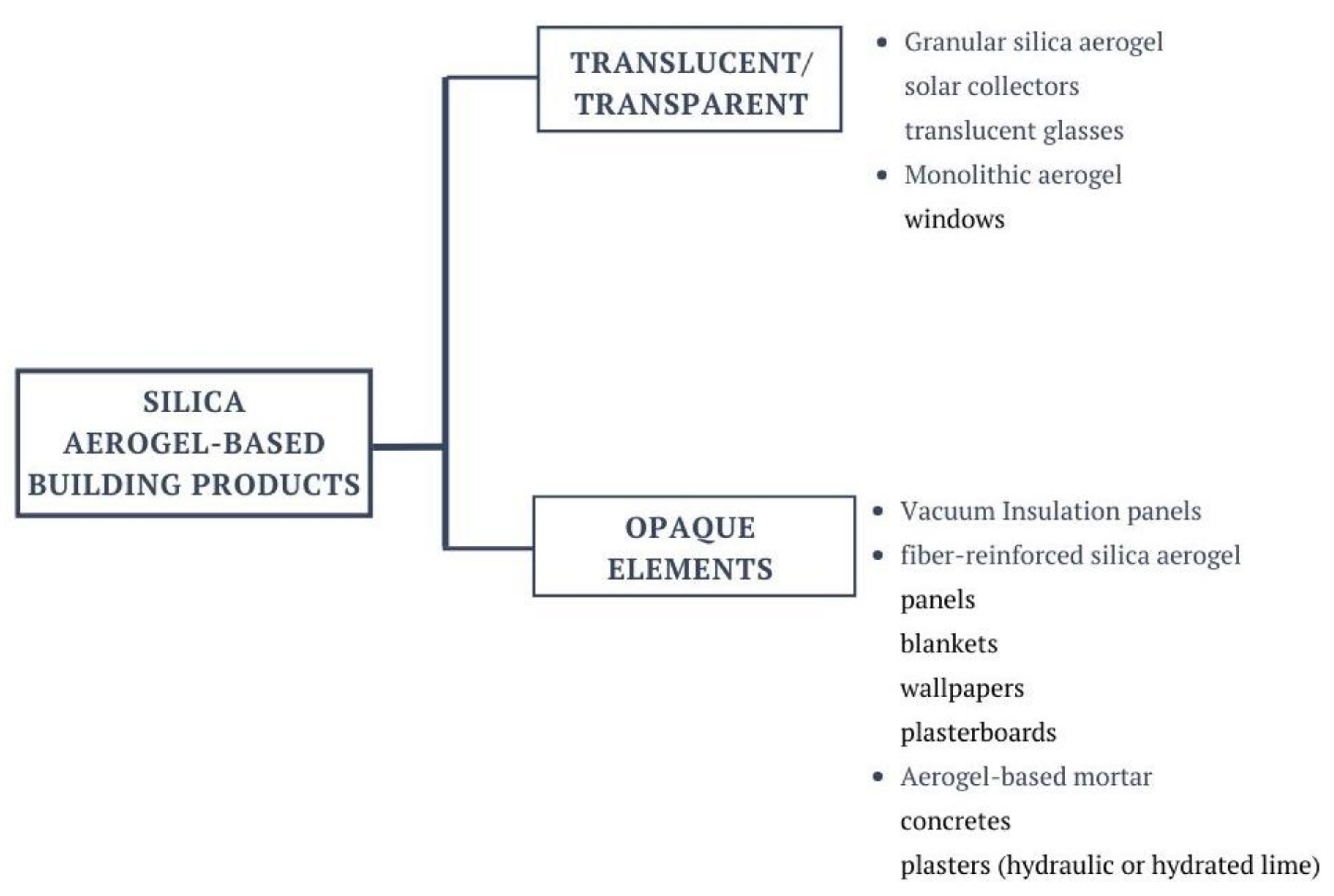
3.1. Aerogel-Based Products for Buildings: An Overview

Amorphous silica aerogel products have been investigated and several applications have been carried out for about two decades. Attempts at a literature review were made in recent years [17,24,25]. Aerogel was discovered in the early 1930s [26], and entered the building sector in the late 1980s, thanks to its high performance as a thermal insulator [17,27]. Up until that time, aerogel was used in the space industry, chemical industry, and sports equipment, but not that much in the building field. A limiting factor was its high cost, and the lengthy tests needed to produce a ready-to-market product [27,28,29]. Aerogel can be used for making slabs, pellets, or other building components. Silica aerogel is the best solid insulator by mass and volume since it transmits one-hundredth of the heat compared to a normal density glass [29]. Aerogel-based building products are currently considered to be promising insulation materials mostly due to the fact they have high thermal performances with limited thickness. Furthermore, they have a very low embodied energy, lower than traditional insulation products. Commercial aerogel-based products have low thermal conductivity up to 0.013 W/(mK). Silica aerogels combine an extremely high porosity with an intrinsic low pore size (nanopores can be up to 90 vol.%). As a result, the gaseous thermal conductivity has a large influence on the overall thermal conductivity of aerogels [17]. Aerogel is nowadays used as a component for several insulating solutions and building products: glass, vacuum insulation panel (VIP), boards, blankets, wallpapers, wall paintings, reinforced concrete, mortars, plasters [30] (Figure 1).
Aerogel can be applied as translucent or transparent insulation, as it combines low thermal conductivity and high transmittance of light and solar radiation [31,32]. Research conducted in the first decade of the new millennium investigated how to develop highly-insulating windows based on granular aerogel and monolithic aerogel [17,31,32,33]. Richter et al. (1995) explain the advantages of applying transparent and translucent silica aerogel in passive solar energy devices [27]. One of the applications of aerogel as a translucent insulator proposed is on external walls. The solar radiation transmits through the aerogel and heats the wall behind. If wall conductivity is high compared to the aerogel, the energy of the solar radiation flows into the building. In the case of a massive wall, the heat can also be stored [27,34]. Another investigated use was to enhance the performance of solar water heaters. An aerogel solar collector operating at a fluid temperature of 60° K above air temperature requires solar irradiation of only 90 W/m2, whereas a current, commercially available flat plate collector is only able to use intensities above 240 W/m2 [24,29,35]. Applications of the silica-aerogel in transparent external partitions are interesting. Specific studies have mainly been conducted since the early 2000s [17,24,34]. Granular aerogel provides windows with good thermal insulation. Nevertheless, it is characterized by low transparency, and windows therefore have a translucent appearance. Aerogel is not transparent enough to be used in double-glazed windows. Moreover, despite their superior efficiency, the cost of production of aerogel panes is rather high if compared to alternative products [24]. Monolithic silica aerogel is suitable for making window glass since it is transparent, and thermal transmittance can be up to approximately 0.5 W/m2K [17]. When inserted between two layers of glass, silica aerogel increases the thermal resistance of double-glazed windows [24]. Since transparent partitions are not the specific subject of this research, further detail on the applications of silica-aerogel to windows is not reported in this paper.
Opaque aerogel-based panels and plasterboards have been developed. These are suitable for insulating the building envelope without excessively increasing wall thickness.
Vacuum insulation panel (VIP) technology has provided a basis for making state-of-the-art aerogel-based solutions. VIP requires the removal of any inner air, having a pressed silica aerogel core, and an airtight coating, usually in aluminium, or other reflective metal material, which increases thermal insulation thanks to the reflection of thermal radiation. More specifically, VIP consists of a core material with small pores (10–100 nm), enclosed in a thin laminate film with low gas permeability. The core material is evacuated to pressures of 0.2–3 mbar, which, depending on the core material, gives a thermal conductivity of 0.002–0.004 W/(mK). Since the laminate is not perfectly gas-tight, gas molecules diffuse through the envelope, so the pressure irreversibly increases in the VIP. The pressure increases according to the core material, type of laminate, and the surrounding climate [24]. The result is a high-insulating performance with limited thickness [36]. The most critical drawback is that VIP cannot be cut to size on a building site or perforated without losing a large part of their thermal insulation performance, because it would cause an increase in the thermal conductivity up to 0.02 W/(mK) [37]. Customizing the size of the panels may therefore cause a significant increase in costs. Moreover, if a VIP breaks, it loses its insulating properties. These negative aspects have led to their scarce use [34].
Opaque aerogel-based insulation products include boards, blankets, wallpapers, and plasters in which fibers reinforce aerogel. Since silica aerogel has low mechanical strength and stability, non-woven fibers (carbon, mineral, or glass fibers) are used as a reinforcement [38] (Table 1). When the fibers, or the fibrous matrix, are added to the pre-gel mixture, which contains the gel precursors, the resulting dried composite is an aerogel-based panel. Examples of aerogel-based reinforced products are Ama Nanotech’s insulations by Aspen. Aspen developed boards based on silica-aerogel technology combined with polypropylene, glass fibers, and/or drywall board.
Aerogel-based plasterboard is made of gypsum or concrete, increasing thermal resistance but with less flexibility than low-density fiber panels [18,38]. Lucchi 2015 [39] cited a rigid panel (Aerowool by Rockwool®), made of a rock wool matrix combined with silica aerogel, which is coated on one side with a gypsum fiber layer and with the interposition of a vapor barrier (conductivity 0.019 W/mK; equivalent air thickness about 3 cm), high breathability, and low aesthetic and material invasiveness. The vapor barrier prevents any interstitial condensation from compromising the insulation. Almost ten years ago, Beatens et al. (2011) reported Aspen’s products as innovative, citing, in particular, the Spaceloft® product. The marketing of these products is now well underway. Spaceloft by Aspen has a thermal conductivity of 0.015 W/mK at 0 °C [38,39]. The peculiarity of this product is that a rather thin flexible blanket (th. 10 mm) is suitable for narrow curves and limited interior spaces (floors, walls) and thermal conductivity is 2–2.5 times lower than traditional thermal insulation materials [17]. One more reinforced aerogel-based insulation was developed for pipe insulation (Nanogel® Compression PackTM by Cabot Aerogel). Thanks to its low conductivity, this product reduces the pipe diameter. The product is delivered as a flat blanket [17]. The same company subsequently marketed insulating blankets (th. 3.5–6–8 mm). These are panels made of aerogel insulation coupled with a breathable polypropylene membrane, reinforced with glass fiber (e.g., Aeropan®), aerogel-based insulation with a bituminous membrane, that guarantees thermal insulation, compressive strength, dimensional stability, and a first waterproof layer, suitable for roof insulation. A thermal barrier strip with aerogel blankets is also available on the market. They are specifically designed to break thermal bridges for door and window frames (e.g., Proloft®) [38].
Historic Scotland carried out tests on a range of traditional properties in Scotland (2012). The issue was how to improve the thermal performance of stone buildings, limiting costs, and maintaining architectural authenticity. They applied a 10 mm thick aerogel blanket directly to the wall surface. Results showed a high level of vapor permeability, and the product, therefore, proved appropriate for retrofitting a historic structure. “Historic Scotland” tests showed aerogel to have a reasonable level of vapor permeability, and therefore it felt appropriate to apply this directly to traditionally constructed mass masonry [40,41].
EURAC Research tested a blow-in aerogel-based insulation as part of the EFFESUS (Energy Efficiency for EU Historic Districts Sustainability) project (2017) [42,43]. The Scotland Proctor Group developed a new type of blow-in insulation which is suitable for gaps and cavities in historic masonry (Spacefill®). The aim was to create a product to guarantee compatibility, reversibility, and minimal intervention. The company made use of the collaboration of Stuttgart University and EURAC Research, which followed the various production phases, verifying its thermal performance. After a series of experiments, polyester fiber enhanced with aerogel powder was considered the best choice. The fibrous polyester material is characterized by robustness, high thermal performance (conductivity 0.014 W/mK), low vapor, and high water resistance. The medium was impregnated with silica aerogel to further improve thermal performance. The aerogel-based blanket was cut into 0.005 mc since it resulted in being the best fiber size for the installation process. This composition permits good thermal performance (conductivity = 0.0255 W/mK, density = 70 kg/m3) and installation is possible using commercial blowing machines [43].
Cellulose-based aerogel was recently investigated, as it could represent a cost-effective bio-based solution suitable for thermal building insulation (thermal conductivity < 0.025 W/mK). This range of thermal conductivity seems to be a consequence of an interplay of several factors (a non-interconnected porous morphology, pore size below 70 nm). Low density (<0.025 g cm−3) is also required to decrease the contribution of heat conduction through the solid matrix [44]. Cellulose-based aerogel and its building uses are still under development and testing. Illera et al. (2018) proposed further improvements to create a sustainable and high-performance material. They stress the need for a standard protocol to characterize the thermal performances of these products and to compare the results of different research. The guarded hot-plate technique is considered the most accurate and reliable method to assess thermal conductivity [44].
An innovative solution was recently developed by Masera et al. (2016) as part of the EASEE research project. It consists of a lightweight, aerogel-based wallpaper that could be installed on the inner side of a wall, making it a possible alternative to plastering. The product is made of an aerogel-impregnated textile mat and a finishing fabric [45]. The finishing fabric system was designed to provide the possibility of easy tensioning and disassembly for cleaning or replacement. The product is easy to use and to replace, thanks to a bespoke tensioning device. The study analyzed its thermal performance together with its permeability to water vapor, which was fundamental to assess whether the insulation is compatible with traditional masonry [45]. Galliano et al. (2016) [46] experimentally compared some insulation kits on a building façade on the university campus “Leonardo-Città Studi”, Politecnico of Milan. The test façade belongs to the building “La Nave” (the ship). It was built in 1965 based on a design by architect Giò Ponti and is nowadays listed as a cultural heritage site. It is made of a concrete and steel structure and non-load bearing cavity walls. The aim of the research was to assess the transient hygrothermal behavior of prototype insulating kits, including aerogel-based kits. The thermal performances of aerogel-embedded wallpapers were parametrically analyzed. Simulated and experimentally measured values were compared also. B.1 kit was an expanded, recycled, glass-based, flat panel, with multilayers of silica aerogel, non-woven polyester textile. The U-value was between 0.50 and 0.62 W/m2K. The B.2 kit was a permeable wallpaper composed of an aerogel blanket and a finishing fabric. The U-value was between 0.66 and 0.73 W/m2K. In conclusion, the authors proposed to further investigate the long-term performance of these solutions, to assess how different climates and different kinds of masonry could affect the results and result in a performance deterioration [46].
Aerogel-enhanced wall coatings (e.g., Thermogel® by Ama of Aspen and EcoThermo Paint® Air by BioTech, cf. Ama, Thermogel® datasheet) are thermal reflective paints that should help block the dispersion of energy through the walls, reducing thermal bridges and preventing the risk of mold.
Silica-aerogel has also been used to make concrete structures with good thermal performance. An aerogel-enhanced concrete is obtained by embedding silica aerogel granules in a high-strength cement matrix, combining the benefits of conventional concrete (compressive strength, moldability) with the properties of a heat-insulating material. Ratke et al. (2008) presented aerogel-incorporated concrete with excellent acoustic insulation and fire resistance [21,47]. Kim et al. (2013) described the performance of a lightweight aerogel-incorporated concrete based on aerogel powder and cement [48]. Different percentages of aerogel were used to feed the mixture mass (0.5–2.0 wt.%); 2.0 wt.% of aerogel provided thermal conductivity decreases of about 75% [21,49]. Similarly, Gao et al. (2014) investigated lightweight aerogel-incorporated concrete (AIC) prepared by replacing the ordinary aggregate of concrete with silica aerogel particles [21,49]. AIC samples were prepared by adding cement, sand, silica fume, water, superplasticizer, and aerogel particles. The cement density was approximately 3140 kg/m3. Hydrophobic aerogel granules with a density of 100 kg/m3 were added (0–60 vol.%) together with distilled water, i.e., the water–binder ratio was set to 0.4. The thermal conductivity of AIC samples was tested with a Hot-disk Thermal Constants Analyzer and a disk-type Kapton Sensor 5465, which operates both as a heat source and temperature record. A typical AIC sample has a density of about 1.0 g/cm3, a thermal conductivity of about 0.26 W/mK, compressive strength of about 8.3 MPa (aerogel content of 60 vol.%). Tests highlight that density, thermal conductivity, and mechanical strength decrease as the aerogel content increases [49]. Fickler et al. (2015) [50] developed a high-performance aerogel concrete. Various mixtures were examined in terms of strength, and thermal conductivity. These results were achieved with a compressive strength between 3.0 MPa and 23.6 MPa and thermal conductivities between 0.16 W/(mK) and 0.37 W/(mK). The bulk density and the compressive strength decreased in comparison with conventional concrete with a silica aerogel content of 70 vol.%. The compressive strength can be increased by reducing the percentage of aerogel granules to a minimum of 60 vol.%. The product was tested with the transient hot bridge (THB) measurement principle, and thermal conductivity was variable, in the range 0.16–0.37 W/mK, with a variable compressive strength of 6–23 MPa. The most appropriate mixture achieved a compressive strength of 10 MPa, a density of 860 kg/m3, and thermal conductivity of 0.17 W/mK [50]. Serina et al. (2015) [51] conducted an experimental investigation of aerogel-incorporated mortar (AIM) with up to 80 vol.% aerogel, prepared by a reduced ultrahigh-performance concrete (UHPC) mixture. The mechanical strength properties of the AIM samples were measured according to DIN EN 196-1 standard, while thermal conductivity was measured with a hot plate thermal constant analyzer. Flexural and compressive strengths decrease with aerogel.20 vol.% aerogel made compressive strength decrease from 120 to 70 MPa (42%); 50 vol.% aerogel had a compressive strength of 20 MPa and thermal conductivity of about 0.55 W/mK; 70 vol.% Aerogel further lowered thermal conductivity by 20%; 80 vol.% aerogel had the lowest compressive strength, approx. 4 MPa [51].
Finally, aerogel-based opaque products include the silica aerogel-base renders, obtained by embedding the aerogel as a porous material component. These products are the principal topic of the study presented with this paper. Renders with silica aerogel have proven to be a super-insulating coating. They are particularly useful when it is necessary to insulate a wall without increasing thickness too much [18,21,23]. Plasters are relatively easy to implement, both on internal and external wall surfaces, and can fill gaps and joints to create a continuous insulation layer [18]. Insulation plasters are suitable for many applications, including outdoor and indoor wall systems. Aerogel-based insulating plasters have been developed as high-performance insulation materials and are easy to use in several situations. These products, made of lime or concrete mortar and silica aerogel, are nowadays commercially available and are constantly under technical evolution. Lightweight plaster can be used for several applications, thanks to its weight ratio, heat insulation, and sound insulation performance, which are higher than traditional plasters [20]. Aerogel is used as an aggregate that contributes to lowering weight, increasing thermal and acoustic insulation, and improving fire resistance. In 2012, Koebel et al. [52] described the innovative aerogel-based render developed at the Swiss Federal Institute for Materials Science and Technology (Empa) together with the Fixit group. The plaster contained more than 80% silica aerogel granulate in volume and could be sprayed on walls using conventional industrial machine-based systems. Thermal conductivity values below 0.025 W/mK were measured. Koebel et al. also cited the plaster-based products by Parexlanko and MINES ParisTech/AR-MINES/CEP. Their goal was to obtain a good thermo-mechanical compromise for external application, using methods as close as possible to traditional ones (e.g., cement-based mortars, traditional techniques). Some mortars with thermal conductivity values close to 0.050 W/mK (hot-guarded plate method) and a flexural strength larger than 0.5 MPa were produced at preindustrial level [52]. Ibrahim et al. (2015) developed an insulating render with low thermal conductivity based on the (super)-insulating capability of silica aerogels. It is a plaster made of a light mortar, that consists of a hydraulic binder (mineral and/or organic) and an insulating filler comprising hydrophobic silica aerogel powder or granules, structuralizing filler (optional), and additives (optional). The aerogel granules are produced in a specialized plant, while the mortar is prepared industrially as a dry composition by mixing hydraulic binder and additives, and the mixture of the above-mentioned components is stored in bags and transported to the site for use. The product is mixed with water on the construction site, to obtain a viscous paste suitable for application, which may be by spraying. Thermal conductivity is measured using a guarded hot plate and a heat-flow meter. Thermal conductivity is 0.026 W/mK. WUFI and EnergyPlus software produced numerical simulations. Results show the moisture risk significantly decreases by applying the aerogel-based plaster on the exterior surface of a non-insulated wall [53].
Because of the potentiality of using aerogel-embedded plasters in historic buildings, these products are particularly being studied in the field of cultural heritage. The recent state incentive (“façades bonus”, 2020), which supports the improvement of existing building envelope refurbishments in Italy, makes the aerogel-based renderings a topical issue.

3.2. Silica Aerogel Applied to High-Performance Plasters for Historic Building Restoration

Contemporary conservation is based on continuous maintenance and on keeping historic buildings in use, as this contributes to ensuring their physical preservation (among the others, see Bardeschi 2005 [54], Della Torre 2020 [55], Bianco et al. [56] and Gasparoli 2006 [57]). A respectful improvement of thermal performance enhances the possibility of continuation of use of a historic building, that is, contributing to its preservation. On the other hand, thermal retrofitting may be a source of risk for historic buildings, since adding insulation layers may affect their authenticity and integrity [5,56].
Thermal insulating plasters may represent a good compromise between the needs of preservation and energy improvement [18,19,25,38]. Thanks to their easy installation and reversibility, they are suitable to apply on non-aligned walls, out of square surfaces, and curved areas typical of historic buildings, naturally aside from the case of frescoed walls, stuccoes, or other historic wall decorations. They allow for the creation of a continuous thermal insulation layer by filling the gaps and irregularities of a pre-existing wall, exactly as in the case of a historic building [4,56]. However, while research about aerogel-based panels and mats is already promising, a specific approach is required to study how to embed aerogel into a lime-based or cement-based mortar [38]. Among the aerogel-embedded products, natural binder plasters are preferable when restoring a historic building. Indeed, thanks to its composition, the silica aerogel-based hydrated lime plaster is highly compatible with the traditional massive structure from both a mechanical and hygrothermal point of view.
Stahl et al. (2012) studied a render consisting of hydrophobized granular silica aerogel (60–90 vol.%) and a cement-free binder, since cement is hardly compatible with the pre-industrial materials used in a historic wall, on both a chemical and physical level [18]. Cement increases a wall’s impermeability, makes humidity stagnate, and favors salt efflorescence [21,58]. This render consists of hydrophobized granular silica aerogel (60–90 vol.%), purely mineral and cement-free binder, plus some additives which enhance workability. It can be applied both manually and via plastering machines. Its thermal conductivity has been measured by a hot plate device and 25 (±2) mW/mK at a density of approx. 200 kg/m3. The authors stated that thermal conductivity is probably affected because liquid water enters the aerogel granulates’ nanopores. Water partially damages the aerogel structure, remains trapped, and needs a long time to dry. According to the authors, cement binders may reduce this risk thanks to their higher resistance compared to lime. Nevertheless, cement may affect breathability and mechanical compatibility with the masonry of the pre-existing building. This cement-free product has low resistance to water vapor. It may reduce moisture accumulation on the cold side of the insulation layer (in summertime) and the warm side of the insulation (in wintertime).
The investigations by Buratti et al., (2014) [19] are interesting in refurbishment as the tested product is currently marketed primarily as a restoration product, Tillica pasta® by Arte e Mestieri s.n.c. [19,59]. They studied aerogel-based renderings and tested the hydrated lime plaster called Tillica pasta, a good restoration material due to its components, and in particular the properties of the naturally mature lime. The composition determines the natural property of water repellent and vapor permeability. Thermal conductivity was measured with a heat flow meter apparatus and it resulted in being proportional to the percentage of granular silica aerogel, as shown in Table 2. The authors tested three solutions with different percentages of aerogel, up to 99 vol.%. The thermal properties of the proposed plasters were evaluated, employing a heat flow meter apparatus. The 50 vol.% aerogel plaster had a range of thermal conductivity of 0.08–0.06 W/mK [19]. Tillica pasta is a silica aerogel-based render developed by Arte & Mestieri and commercialized by Ibix S.r.l. The product is an aerogel-based mortar obtained by manually mixing slaked natural hydrated lime with granular silica aerogel. Thank to this combination, the product has high porosity (>90%) and interesting thermal behavior and breathability. It is also not putrescible and antibacterial, thanks to the presence of hydrated lime. Declared data: thermal emissivity ε = 0.87 (standard ASTM C 1371-04 a), thermal conductivity = 0.00175 W/mK (UNI 10456), average solar reflectance = 0.47 (standard ASTM1980-11) [59].
The over-cited Ibrahim et al. (2015) [53], with their aerogel-embedded plaster with a hydraulic binder, focused on how the aerogel-based render contributes to lowering the risk of moisture in historic structures. Indeed, due to the hydrophobic nature of the aerogel, aerogel-based renders reduce water absorption, keeping stable both the volumetric composition and thermal behavior [21]. However, it is necessary to consider the risk of low breathability linked to the use of hydraulic instead of hydrated lime.
The Swiss Federal Institute EMPA investigated a pre-mixed aerogel-enhanced plaster commercialized by Röfix with the name of FIXIT 222. This material uses more than 50% silica aerogel granules in volume and declares a thermal conductivity of 0.028 W/mK [23,38]. Nosrati and Berardi (2017) investigated aerogel-enhanced plasters with different percentages of silica aerogel [60]. The aim was to assess the performance of the proposed renders as insulation materials. The experimentation was performed at the Building Science Laboratory at Ryerson University, in Toronto. The samples were prepared by mixing hydraulic lime-based plaster with granular silica aerogels P300 in different percentages (from 25% to 95 vol.%). Three groups of aerogel-enhanced plasters were considered: FIXIT 222, NHL 3.5 hydraulic lime by CHIRAEMA s.r.l., NHL 3.5 Saint Astier by TransMineral USA. The thermal conductivity of the samples was measured with a heat flow meter apparatus. Samples had different thicknesses and they were placed between a hot and a cold plate. Thermal conductivity was measured up to reaching the thermal equilibrium at a pre-defined difference of temperature between the plates. The results highlight a direct relationship between plaster density and thermal conductivity [60].
Ghazi Wakili, Stahl et al. (2015) investigated the long-term behavior of an aerogel-based plaster applied without reinforcement meshes. The test was made on a wall of the historic main building of TU Wien. Temperature, humidity, and heat flux were monitored within different layers of the wall by using a wireless sensor system [20]. Fixit 222 aerogel plaster was applied to four testing areas on the southern façade, which dates back to the 1950s. Wall stratigraphy before testing was: 1.5 cm gypsum plaster on the indoor side, 5 cm hollow bricks, 2 cm cement rendering on the outdoor side. Sensors were installed on both the indoor and outdoor surface in late 2013 to measure temperature, moisture, and heat flux before the retrofit. Five months later, in 2014, the F222 plaster (thickness = 4 cm) was applied to each of the four areas with different finishes (difference in grain and finish, painting, water repellent, etc.). After retrofitting, Area 1: Ubefore = 0.97 W/m2k, Uafter = 0.78 W/m2k (−20%). Area 2: Ubefore = 1.04 W/m2k, Uafter = 0.58 W/m2k (−45%). The U-values decreased less than expected, probably due to the fact that the drying process was not yet completed. [20]. The on-field research was therefore further implemented two years later. Shuss et al. (2017) tested different aerogel-based plaster systems thanks to ten sample areas on the façades of the TU Wien’s main building: four test areas on the southern façade (S), four on the western façade (W), two on the northern façade (N). Temperature and humidity were constantly monitored, along with the weather conditions. These products were applied to the southern façade:
-
S1: Fixit 223 embedding mortar with reinforcement mesh + Röfix 380 fine-grain lime plaster + RöfixPE 819 Sesco Öko lime color with high vapor permeability;
-
S2: Röfix 223 new + Röfix 380 fine-grain lime plaster + RöfixPE 819 Sesco Öko lime colour;
-
S3: Röfix 223 new + Röfix 775 7–10 mm grain plaster + Röfix PE 225 Reno 1 K Silikatfarbe with high vapor permeability;
-
S4: Röfix 223 new + Röfix 380 fine-grain lime plaster + Roöfix PE 419 Etics with high vapor permeability.
The parameters declared by the datasheet were experimentally verified on-site. The U-value measured on-site was found to be similar to what was declared, and close monitoring of the water content proved to be crucial to confirm these data [10]. A 4 cm aerogel-based plaster was applied to both sides of an existing 42 cm brick wall. As a result, U-value lowered from 1.25 to 0.46 W/m2K (−64%) [22]. This confirmed the high thermal performance of the aerogel-based plasters even at a very limited thickness. On this side, confirmation was obtained of its suitability for the energy retrofitting of heritage buildings.
Besides the advantages, the aerogel-embedded renders and the method used for characterizing their properties present some criticalities which are still under investigation. Stahl (2012) confirmed the role of water is crucial to assess plaster behavior over time. Measuring the pore size and distribution, mapping their microscopic structure is, therefore, a way to better understand how moisture penetrates within the porous material [18].
Durability is a very important issue for aerogel-based renders. Nosrati and Berardi (2017) compared the durability of three aerogel-based plasters available on the market: FIXIT 222, Saint Astier, Chiraema. The samples were exposed to different aging stressors, including high temperature and high humidity, freezing-thawing cycle. The thermal properties of each product were measured before, during, and after the aging period, by using a heat flow meter apparatus, according to standard ASTM C518. The thermal resistance of all samples decreased by about 17% after a nine-year equivalent aging time. Similarly, the thermal conductivity of all samples significantly increased after a 15-year equivalent aging time. According to the authors, aerogel-based plasters lose their thermal resistance faster than aerogel boards and blankets. This is due to physical changes in the porous structure of the aerogel-based plasters over time, as shown by the SEM images taken before and after the aging process. Results thus demonstrate that thermal performance depends on both sample composition and aging factors [60]. The same authors (2018) continued this research by simulating 20 years of aging [61]. Each stress condition was individually tested and then combined to understand better the effect of each factor of decay (high temperature, high humidity, freeze-thaw cycle, UV exposure combined with high temperature and high humidity). Although the combination of different elements made thermal conductivity rise, high humidity resulted as the main factor affecting this parameter. The authors tested samples of plaster made of natural hydraulic lime (NHL 3.5–55 lbs, by Sustainable Innovative Products and Chireama Corp.) enhanced with a percentage of hydrophobized silica aerogel granules (P-300, supplied by Cabot Corp) from 25 to 90 vol.%. Samples had dimensions 15 × 15 × 2 cm. After 20-years equivalent aging time with high humidity levels, 70% of samples increased thermal conductivity up to 10%. However, despite the aging-driven rise, the thermal conductivity of aerogel-based plasters stayed much lower compared to not-aged conventional materials [60,61].
Following this literature overview, future research will further analyze the physical and mechanical features of silica aerogel plasters and the connection between product composition and environmental conditions of use. The authors want to stress that the understanding of the thermal performance related to conditions of use and the product thickness is still limited by the lack of a long-term experience [46,61]. Analyzing the porous structure (e.g., pore diameter, total pore volume) and assessing the vapor permeability of market products is therefore crucial, as they greatly affect both indoor and outdoor durability. The effects of acid rain should also be more thoroughly investigated [62,63].
The second significant criticality, which is highlighted in the specific literature [21,23], is the higher cost of aerogel-based products compared to traditional building materials. Indeed, this feature is a disincentive for the adoption of aerogel-embedded plaster systems. Opaque aerogel-based products may cost ten times as much as a common insulation material such as mineral wool [24]. However, the aerogel market has exponentially increased together with the number of companies that produce patents. The global market for silica aerogel products was estimated at $307.5 million (US) in 2014, $427 million in 2016, and is expected to reach 1.92 billion by 2022, with an annual growth of over 10% [30]. The overall review of thermal insulating plasters in the European market, carried out by Barbero et al. (2014) [64], considered the costs of aerogel-based renders. They considered technical data and prices that were directly supplied by producers, without publishing names of manufacturers and commercial products for reasons of privacy [21]. This analysis was resumed by Buratti et al. 2016 [21]. Barbero et al. determined the average cost of a product with the exclusion of the higher parameters in each system analyzed [63]. The incidence of the cost of plasters was assessed by considering both the cost per square meter of each plaster necessary to obtain the same final thermal resistance (equal thermal resistance Rx for 1 m2 K/W) and the cost per functional unit (the reference unit is the money required to make 1 cm of thickness) [21,64] (Table 3).
It is useful to analyze the influence of aerogel costs on the optimum thickness of the render. The cost analyses by Barbero et al. allowed a price range to be determined, which constitutes the optimum. A new thermal insulating plaster should have a cost of around 45–60 €/m2, with the same thermal performance with Rx values [64]. It is therefore important to understand the optimal thickness related to the render cost. Buratti et al. explained that as the cost increases the optimum, the thickness value decreases [21]. Further research developments should investigate the relationship between thickness and costs further, considering the thermal conductivity and the durability of the final render. It is necessary to test plaster with different compositions and different percentages of silica-aerogel.
The increasing interest in the building products described above largely depends on the certified thermal performance parameters. This information is the only data that the manufacturers can use to demonstrate the features and the benefits of their products, so it is necessary to obtain results that are calculated with formulas and laboratory tests, as that corresponds as much as possible to the performance of the product in use. Sample manufacture is relevant to understanding the thermal behavior of the building product. The thickness of the aerogel plaster influences the final behavior of the material in the relative condition of use and this feature is fundamental for the quality-cost ratio, especially in the case of restricted historical construction. From the literature review, it is clear that there is no single guideline for laboratory thermal tests (the type of tests and the manufacture of specimens).

4. Thermal Characterization of Aerogel-Based Plasters

The increasing interest in the above-described aerogel-based products largely rests on certified thermal performance parameters. These data are indeed the only information available to the manufacturers to prove the benefits of these products. It is, therefore, necessary to obtain results from precise methods and repeatable laboratory tests. Most authors refer to the international technical standards that regulate the tests to assess the thermal parameters of the insulating materials. However, from the above-described literature review, various procedures emerge for testing the thermal performances of aerogel-based products. Some authors compared results obtained with different methods, including the outcomes from simulations and in-situ tests [46,65,66]. Although there is a tendency to check among different methods and evaluation guidelines, a clear and unique guideline is lacking. Moreover, the samples destined for laboratory tests must be as representative as possible of the products in use. The thickness indeed influences the final behavior of an aerogel-based plaster in terms of thermal performance, compatibility, durability, and cost. The method for manufacturing the samples destined for laboratory tests is, therefore, crucial. Nevertheless, a clear procedure for manufacturing specimens destined for laboratory tests is lacking.

4.1. Technical Standards and Thermal Test for Building Insulation Products

International and European standardization bodies developed a series of procedures for laboratory tests to define the energy requirements of building insulation products. The standardized methods for the thermal characterization of insulating materials are the following:
-
Guarded Hot Plate (GHP) method (ISO 8302, UNI EN 12667);
-
Heat Flow Meter (HFM) method (ISO 8301, UNI EN 12667, UNI EN 12664);
-
Guarded Hot Box (GHB) (UNI EN ISO 8990);
-
Hotbox chamber with heat flow meters (UNI EN 1934);
-
Radial method (UNI EN ISO 8497).
Table 4 summarizes methods and related standards for the thermal laboratory characterization.
The guarded hot plate and the heat flow meter methods are used for the thermal characterization of homogeneous materials, without thermal bridges [68].
The Guarded Hot Plate (GHP) defines the transportation of energy, in the form of heat, which passes through the specimen due to a certain temperature gradient in steady-state conditions. The method is normalized by the ISO 8302 standard, implemented in Europe with the EN 12664 and EN 12667 standards. The main instrumentation consists of the central measuring element and a guard ring, which is kept at the same temperature as the central element, to generate a one-dimensional heat flux. In the “single specimen” apparatus, there is a heating element, the hot plate, with a central measuring area, and the guard ring, placed at the edge. Above is the cold plate, of the same size as the heating element. An external chiller cools the refrigerant fluid contained in the cooling unit. The plates are surrounded by an insulating material to avoid heat loss during the test. The specimen is placed between the heating and cooling elements. Reaching the dew temperature produces air condensation inside the equipment, and to dry the air, nitrogen is blown through a small tube inserted before starting the test. For each sample, the test is carried out in ascending flow conditions, by entering a defined temperature range. The data are processed with special software, setting the parameters relating to the size of the specimen and the temperature ranges, as well as the calibration data. The Guarded Hot Plate (GHP) is considered the most accurate and reliable method for determining thermal conductivity, although other techniques such as transient hot-wire/hot disk and laser flash analysis represent possible alternatives [69].
The Heat Flow Meter (HFM) determines the thermal flux density by measuring the temperature difference that is generated on a layer of calibrated material placed in series with the sample under test. The HFM consists of two plates with the test sample placed between them. Each plate has its heat flow sensor, located in the central area. Working with a smaller measuring area than the dimensions of the samples reduces measurement error due to lateral heat losses. The temperature differences between hot and cold plates should be between 10 K and 30 K. The top plate acts like a hot plate and the bottom one is a refrigerated plate, so steady conditions can be obtained by placing the sample between these two plates. In each plate, there are three types of thermocouples. The thermal resistance of the tested sample is calculated using the measured average temperatures of each plate and the average heat flow of the two plates. Two different standards are applied, based on the thermal resistance values of the products, the EN 12667 and the EN 12664. The difference between the two standards concerns the methods for measuring the temperature difference across the sample [68].
The Guarded Hot Box (GHB) method is used to characterize the type of walls that present thermal bridges. The wall specimen is positioned between a hot room and a cold room. In the guarded method, the measuring chamber is surrounded by the guard chamber, which is kept at the same temperature as the measuring chamber. Under these conditions, all the heat generated electrically in the measuring chamber passes through the sample and the thermal transmittance “U” is evaluated considering the thermal difference between the two chambers and corrected to refer to the usual surface resistance. If the tested wall is homogeneous on average, meaning variations in surface temperature are less than 20% of the temperature difference, it is possible to obtain thermal resistance considering the temperature jump between the surfaces of the specimen under test. The reference standards for the hot box test are the BS EN ISO 1934: 1998 and 8990: 1996 standards.
If the samples are non-homogeneous or have cavities in which convection can become possible, the measurement section of the heat flow may not cover a representative area. For these specimens, it is better to use protected or calibrated hot box instrumentation (EN ISO 8990). In the calibrated method, the measuring chamber is surrounded directly by the laboratory environment, making it impossible to eliminate the thermal flow through its sides, as happens in the guarded method. In this situation, the heat flux which is dispersed by the chamber is evaluated through the temperature difference on its sides. In the case of masonry walls, the hot box method can also be applied with flow meters, in accordance with the standard EN 1934. In this case, the heat flow through the wall specimen is measured by a flow meter placed on the sample’s hot surface. The flow meter must be large enough to cover the wall’s non-homogeneities [68,69].
The radial method (EN ISO 8497) applies to insulating materials for pipes. The heating element consists of a circular tube at the ends of which there are two cylindrical heaters, which are kept at the same temperature to minimize axial heat flows (guarded method), or calibrated extremities may be present to evaluate the axial dispersions [68].
Standards regarding thermal characterization of building products impose the laboratory tests. The in-situ tests have greater measurement uncertainty, given that thermal measurements are significantly influenced by surrounding thermal conditions, which are difficult to control. The high variability of the boundary conditions causes errors. Therefore, the laboratory tests play a fundamental role in the analysis and characterization of building insulation materials. Specific certification bodies belonging to the EA (European cooperation for Accreditation) are responsible for certifying test laboratories according to the UNI EN I-SO/IEC 17025 [68].

4.2. Specimens Manufacturing for Thermal Laboratory Tests

International standards only partially address the issue of how samples should be manufactured. UNI EN 12664:2001 standards regarding the determination of thermal resistance using both GHP and HFM methods, prescribe general criteria to manufacture specimens. One or two specimens shall be selected from each sample, according to the type of apparatus (UNI EN 12664:2001, par. 5.2.-5.2.3, 5.3.1). When two specimens are required, they must be as identical as possible, with thicknesses differing by less than 2%. The size of the samples should cover the heating unit surfaces completely, but they should not exceed the overall linear dimension of the heating unit or heat flow meter by more than 3%. The thickness should be according to the relevant product standard and the relationship between the thickness and the dimensions of the heating unit should be restricted to limit the sum of the errors to 0.5%. For layered non-homogeneous composite specimens, the estimated thermal conductivity of each layer should be less than twice that of any other layer, because of need of good accuracy of the rest. The boundary conditions at the edges due to the effects of edge insulation, auxiliary guard heaters, and surrounding ambient temperature, affect the edge heat loss error and limit the maximum thickness (UNI EN 12664:2001, par. 6.2, Annex A.3). Table A.1 of the standard UNI 12664:2001 (Annex A.1) prescribes the maximum and minimum thickness of the specimens (Table 5 and Table 6). These thicknesses may be increased by 50% if the requirements of EN 1946-3:1999 are complied with (par. 4.4–4.6).
Samples of cement or masonry materials must be prepared 28 days in advance because they initially contain a large amount of water. The specimens’ surface must be flat to allow close contact between the sample and the measuring apparatus. For rigid materials, the samples’ faces have to be as flat as the apparatus surfaces and must be parallel over the total surface (defects are acceptable under 2% of the specimen thickness). In the case of cellular or aggregate products, defects over and above the naturally occurring (e.g., scratches or chips) are accepted, provided that the total of their area is an acceptable fraction of the metering area and their maximum depth is an acceptable fraction of the whole thickness (UNI EN 12664:2001, par. 6.3.2.1). The samples for porous and homogeneous materials are representative provided that any non-homogeneity is smaller than one-tenth the height of the sample (EN 12664:2001, Annex B.5, ISO 8302:1991-1.8.2). The samples’ thickness has to be larger than the thickness that produces a transmissivity heat change, which is more than 2% (EN 12664:2001, Annex B.5, ISO 8302:1991-1.8.3.1). The thinner and less dense the material, the more likely thermal resistance will depend on processes other than conduction. It is believed that a lower limit thickness exists for many materials. Below that limit, such dependence occurs. If the minimum thickness is unknown, it must be experimentally estimated, even if there is no established procedure for such a measurement (ISO 8302:1991). In the calibrated hot box, the sample frame is critical. Flanking losses must indeed be kept to a minimum, not to affect the accuracy of the test. The facing towards the sample should have low thermal transmission, while side heat flow must be minimized by insulating the edges of the sample (UNI EN ISO 8990:1996, par. 2.5).
Besides technical standards, the above literature review highlights how the authors have used different specimens because of the many possible applications and tests. Authors have indeed generally described the materials and methods of their studies, while providing few details on the preparation of the samples. Stahl (2012) used a guarded hot plate apparatus [18]. The specimen size was 65 × 65 mm and 12–13 mm thickness. The samples were manually made and dried in a climatic chamber for 28 days (23 °C, 50% R.H.). Buratti et al. (2014) used the heat flow meter apparatus together with a 300 mm × 300 mm sample made of two layers: a plasterboard support (thickness = 12.5 mm) + aerogel-based plaster (thickness = 24.5 × 44.5 mm) [19]. Berardi (2017, 2018) used an HFM apparatus [23,38] together with a 150 × 150 mm sample [29]. Table 7 collects the instruments and kind of specimen, as described in the above-mentioned literature review.

5. Results: A Guideline for Assessing the Thermal Performance of Aerogel-Based Plaster

Following the literature review, this paper concludes with the proposal of an experimental guideline aimed at evaluating the thermal behavior of an aerogel-based slaked lime plaster, and with instructions on how to prepare the samples.

5.1. Measurements Guideline

The guideline aims to assess how much thermal performance improves thanks to the application of an additional layer of aerogel-based plaster. A procedure for checking the growth indices (linear or exponential) of conductivity values to the increase in thickness (Samples A1, A2, A3) was defined, considering the possibility of applying the material in thicknesses even greater than 5 mm. This procedure aims to define the best compromise between thermal performance and thickness of the insulating plaster application. In addition to the thermal performance, a wider series of tests aims to characterize the material physically and to assess aging behavior. The test consists of measuring the thermal conductivity of a series of samples by using a heat flow meter, and the GHP method. The test simulates the climatic conditions of the winter period, exposing the samples to a temperature range ΔT = 20 °C, with an outdoor temperature (aerogel-based plaster side) of +/−0 °C, and indoor temperature (hydraulic lime mortar side) of +20 °C. Reference standards are: EN ISO 6946:2017; EN 1745:2012; ASTM C518:2017; EN 12667:2002; ISO 8301:1991. The instruments employed are a Heat Flow Meter together with heating and cooling plates. The measurement of conductivity and thermal resistance follows standards EN 12667, ASTM C518, ISO 8301. Following ASTM C518:2017, that considers the reduced thermal conductivity of aerogel-based plasters, five observations for each sample for at least 30 min/each are required. The thermal balance must be verified by observing and recording the output of the heat flow transducer, the average temperature of the samples, the drop across the sample, and the calculated λ value, before taking the measurements. It is necessary to record data until the next five outputs are stable. All five values must fall within 0.5% of the mean value. If the five readings show a monotonous upward or downward trend, equilibrium has not been achieved and therefore further sets of readings must be taken (ASTM C518:2017).

5.2. Instructions for Making the Samples

The samples must comply with the reference standards, and the features mentioned above in Section 4.2. They were designed based on a comparative review of recent literature and technical standards to minimize the influence of the heating/cooling plates during the measurement of the thermal flow between the hot and cold surfaces (Table 8). The sample A0 consists of a brick base + a lime plaster rendering. A further layer of aerogel-based plaster follows in the next three samples (A1, A2, A3), with an increasing thickness (5, 10, 15 mm). Alongside this series of samples with a layer of aerogel-based plaster of increasing thickness, two further samples are required. The first sample aims to provide a term of comparison with another insulating material with already known thermal characteristics, such as sintered expanded polystyrene (EPS). EPS is probably the most widely used material as an insulating coating for existing buildings and represents a standard for the main field of application to which the aerogel-based plaster aspires. Sample B, therefore, has the same stratigraphy as the previous ones, but a 100 mm EPS panel takes the place of the aerogel plaster. The second comparison sample (C) is made only of aerogel-based plaster. By repeating the conductivity measurements on this sample, it will therefore be possible to obtain a reference value to be compared with the other stratified samples.
-
A0: is made of three layers: a core of standard solid brick (two double UNI—Italian National Unification—bricks with a joint of natural hydraulic lime (NHL) mortar, dimensions: 250 × 250 × 50 mm), a 10 mm NHL render on both sides;
-
A1 = A0 + 5 mm layer of aerogel-based plaster (80%);
-
A2 = A0 + 10 mm layer of aerogel-based plaster (80%);
-
A3 = A0 + 15 mm layer of aerogel-based plaster (80%);
-
B = A0 + 100 mm prefinished EPS board;
-
C = 50 mm × 50 mm × 20 mm aerogel-based plaster (80%) only.
Sample B is made of an A0 sample with a layer of expanded polystyrene (EPS) insulation board on the external surface (100 mm thickness). This sample is necessary to calibrate the test and to compare the thermal performances of specimens with aerogel-based render (A1, A2, A3) and a commercial product which has a known and certified performance. It is fundamental to use a commercial product that has been tested and has certified features. The guideline proposes the use of an insulation board made of expanded polystyrene with graphite, certified by the European standard EN 13163 and by ETICS standards; the commercial product has these features: thermal conductivity 0.032 W/mK, vapor permeability: 20–40, fire behavior E1.
This series of samples aims to provide homogeneous support, easy packaging, well-known materials, and compositional structure. They are also able to simulate the real application of plaster on a masonry building. The mortar must be correctly prepared and applied, so as not to alter the physical and mechanical characteristics of the individual components and so as not to affect the reactions during the setting and drying phase. Before testing, all conditions defining the current use of the material must be checked, such as the correct setting, drying, and seasoning. Samples must be stored for a period sufficient to achieve a uniform distribution of internal humidity. Samples must be dried at 105 °C until a constant mass is reached (BS EN ISO 8990:1996, BS EN 1934:1998), as a general custom, and subsequently stored in a polythene bag at a controlled temperature and humidity, following the prescriptions of technical standards.
Further recommendations are, referring to technical standards (8301:1991; UNI EN 1015-19; BS EN ISO 8990:1996; BS EN 1934:1998)
-
The solid bricks to be used for the packaging of the specimens (specimens A0, A1, A2, A3, B) must come from the same plant and the same production batch;
-
The natural hydraulic lime mortar used for packaging the samples must be certified and must have a technical data sheet with all the reference data for the analyses;
-
The laying of the plaster layer in a natural hydraulic lime mortar must take place in a single day using the same mixture for all the samples (specimens A0, A1, A2, A3, B);
-
First, proceed with creating the bases A0 for all the type A samples and the base for the specimen B. Once the layers of plaster have set and dried, proceed with the application of the layers of Tillica pasta in a complete cycle (specimens A0, A1, A2, A3);
-
The application of the plaster layer (complete cycle) must take place in a single day using the same mixture for all samples (specimens A, C);
-
The porous samples must be homogeneous and representative of the materials; any non-homogeneity must have dimensions less than one-tenth of the thickness of the sample;
-
The sample mixture must be prepared in such a way as to not alter the physical and mechanical characteristics of the individual components and in such a way as not to jeopardize the reactions during setting and drying;
-
The test sample must be constructed in such a way that it is representative following common practice; areas that may have different surface temperatures should be included in the measurement area in a representative way;
-
For transportation, all the specimens must be placed individually in suitable polystyrene or polystyrene containers to minimize the possibility of compromising their structure and characteristics;
-
Before the experiment, all the conditions that define the standard use of the material must be verified, such as correct setting, drying, and curing;
-
Samples must be stored for a sufficient period to obtain an even distribution of internal humidity. As a general rule, drying must be carried out at 105 °C until a constant mass is reached;
-
The sample must be placed in a ventilated desiccator under controlled and constant temperature conditions as per material specifications and subsequently stored in a polythene bag at a controlled temperature;
-
The thickness of the samples must be greater than that the one by which the sample, in case of imperfections, cannot vary by more than 2%;
-
The sample must be flat to allow the greatest possible contact between plates, parallel to them during the analyses, and with an inclination not exceeding 2%.
The quantity of water used and its effect, the period of drying before testing, whether oven-drying at 105 °C could affect the sample at an early age must be further detailed.

6. Conclusions

This literature review confirmed that aerogel-based plasters are a highly promising product for improving the energy efficiency of existing buildings, including heritage buildings. A number of promising results is already available.
Regarding aerogel-based plasters, the relationship between the aerogel content and thermal performance improvement should be further investigated. This ratio greatly affects the cost of the product and must be carefully controlled so that the aerogel-based plasters are thermally performing but also economically affordable. Some authors investigated the thermal performance of silica-aerogel renders together with other parameters (composition, vapor permeability, breathability) to assess if they are compatible with the historic structures [18,20,46]. However, most of the on-field tests were implemented on buildings dating back to the second half to the twentieth century. Ancient walls may present more criticalities and deserve higher attention [20,46] and further investigation. Some specific issues need to be further investigated via both laboratory and on-field tests. This is the case of durability which may affect a broader diffusion of these products.
The quality of an insulation product mainly relies on laboratory tests that are easier to control and repeat. After reviewing previous research, market products, and technical standards, the lack of a clear procedure for manufacturing the samples destined for laboratory tests was evident. The guideline we propose aims to provide scholars with a common starting ground on which future studies and experiments could rest. If applied by a significant number of tests, the guideline will therefore be able to validate and further improve results, particularly concerning the field of heritage buildings.

Funding

This research was developed within “D’Ecc project” of the department DAStU (Polytechnic of Milan), Excellence Department by the Italian Ministry of University and Research (2018–2022).

Acknowledgments

The authors thank arch. Andrea Garzulino and arch. Luca Valisi (Politecnico di Milano, Laboratory of Analysis and Analysis and Building Diagnostics) for the collaboration in preparing the guideline for the thermal performance and Table 7.

Conflicts of Interest

The authors declare no conflict of interest

References

  1. Calisesi, M. Aerogel Incorporated Plasters and Mortars: The Case Study of Precast Panels; Degree Course: Building Engineering and Architecture; University of Bologna: Bologna, Italy, 2017. [Google Scholar]
  2. Commissione delle Comunità Europee. Libro Verde Sull’efficienza Energetica: Fare di Più Con Meno; Comunità Europee: Bruxelles, Belgium, 2005. [Google Scholar]
  3. Stephan, A.; Athanassi, A. Towards a more circular construction sector: Estimating and spatialising current and future non-structural material replacement flows to maintain urban building stocks. Resour. Conserv. Recycl. 2018, 119, 248–262. [Google Scholar] [CrossRef]
  4. Lavagna, M. Life Cycle Assessment in Edilizia; Hoepli: Milano, Italy, 2008. [Google Scholar]
  5. Muller, M.F.; Esmanioto, F.; Huber, N.; Loures, E.R.; Junior, O.C. A systematic literature review of interoperability in the green Building Information Modeling lifecycle. J. Clean. Prod. 2019, 223, 397–412. [Google Scholar] [CrossRef]
  6. Agliata, R.; Marino, A.; Mollo, L.; Pariso, P. Historic Building Energy Audit and Retrofit Simulation with Hemp-Lime Plaster. A Case Study. Sustainability 2020, 12, 4620. [Google Scholar] [CrossRef]
  7. Adamczyk, J.; Dylewski, R. The impact of thermal insulation investments on sustainability in the construction sector. Renew. Sustain. Energy Rev. 2017, 80, 421–429. [Google Scholar] [CrossRef]
  8. Cinieri, V.; Zamperini, E. Approccio lifecycle alla gestione e conservazione sostenibile del patrimonio costruito. Sci. Beni Cult. 2014, 30, 723–733. [Google Scholar]
  9. Monticelli, C. Life Cycle Design in Architettura; Maggioli: Santarcangelo di Romagna (RN), Italy, 2013. [Google Scholar]
  10. McDonough, W.; Braungart, M. Cradle to Cradle: Remaking the Way We Make Things; North Point Press: New York, NY, USA, 2003. [Google Scholar]
  11. Pacheco Torgal, F.; Buratti, C.; Kalaiselvam, S.; Granqvist, C.-G.; Ivanov, V. (Eds.) Nano and Biotech; Springer: Cham, Switzerland, 2016. [Google Scholar]
  12. Cinieri, V. Patrimonio edificato diffuso. Un Approccio Sostenibile alla Conservazione e alla Gestione. Ph.D. Thesis, University of Pavia, Pavia, Italy, 2015. [Google Scholar]
  13. Biscontin, G.; Driussi, G. Quale sostenibilità per il restauro? Atti del 30° Convegno di Studi Scienza e Beni Culturali. Sci. Beni Cult. 2014, 1, 964. [Google Scholar]
  14. CRESME. Il Mercato Delle Costruzioni 2013. Lo Scenario di Medio Periodo 2012–2016—XX Rapporto Congiunturale e Previsionale Cresme; CRESME: Rome, Italy, 2012. [Google Scholar]
  15. Mezzi, P. Rapporto Cresme 2019 Sulle Costruzioni: Arrestata la Caduta, si Torna (Poco) a Salire. Il Giornale Dell’architettura. Available online: https://ilgiornaledellarchitettura.com/ (accessed on 28 November 2018).
  16. Ambrogio, K.; Zuppiroli, M. Energia e Restauro; Franco Angeli: Milano, Italy, 2013. [Google Scholar]
  17. Baetens, R.; Jelle, B.P.; Gustavsend, A. Aerogel insulation for building applications: A state-of-the-art review. Energy Build. 2011, 43, 761–769. [Google Scholar] [CrossRef] [Green Version]
  18. Stahl, T.; Brunner, S.; Zimmermann, M.; Ghazi Wakili, K. Thermo-hygric properties of a newly developed aerogel based insulation rendering for both exterior and interior applications. Energy Build. 2012, 44, 114–117. [Google Scholar] [CrossRef]
  19. Buratti, C.; Moretti, E.; Belloni, E.; Agosti, F. Development of Innovative Aerogel Based Plasters: Preliminary Thermal and Acoustic Performance Evaluation. Sustainability 2014, 6, 5839–5852. [Google Scholar] [CrossRef] [Green Version]
  20. Ghazi Wakili, K.; Stahl, T.; Heiduk, E.; Schuss, M.; Vonbank, R.; Pont, U.; Sustr, C.; Wolosiuk, D.; Mahdavi, A. High performance aerogel containing plaster for historic buildings with structured façades. Energy Proced. 2015, 78, 949–954. [Google Scholar] [CrossRef] [Green Version]
  21. Buratti, C.; Moretti, E.; Belloni, E. Aerogel Plasters for Building Energy Efficiency. In Nano and Biotech Based Materials for Energy Building Efficiency; Pacheco Torgal, F., Buratti, C., Kalaiselvam, S., Granqvist, C.G., Ivanov, V., Eds.; Springer: Cham, Switzerland, 2016; pp. 17–40. [Google Scholar]
  22. Schuss, M.; Pont, U.; Mahdavi, A. Long-term experimental performance evaluation of aerogel insulation plaster. Energy Procedia 2017, 132, 508–513. [Google Scholar] [CrossRef]
  23. Berardi, U. Aerogel-enhanced systems for building energy retrofits: Insights from a case study. Energy Build. 2018, 159, 370–381. [Google Scholar] [CrossRef]
  24. Berge, A.; Johansson, P. Literature Review of High Performance Thermal Insulation; Report 2012:2; Chalmers University of Technology: Gothenburg, Sweden, 2012; pp. 1–28. [Google Scholar]
  25. Cuce, E.; Cuce, P.M.; Wood, C.J.; Riffat, S.B. Toward aerogel based thermal superinsulation in buildings: A comprehensive review. Renew. Sust. Energ. Rev. 2014, 34, 273–299. [Google Scholar] [CrossRef]
  26. Kistler, S.S. Coherent Expanded Aerogels and Jellies. Nature 1931, 127, 741. [Google Scholar] [CrossRef]
  27. Richter, K.; Norris, P.M.; Chang, C.-L. Aerogels: Applications, structure, and heat transfer phenomena. In Annual Review of Heat Transfer; Prasad, V., Jaluria, Y., Chen, G., Eds.; Begell House Inc.: Danbury, CT, USA, 1995; Volume 6, pp. 61–114. [Google Scholar]
  28. Schreiber, E.; Boy, E.; Bertsch, K. Aerogel as a Transparent Thermal Insulation Material for Buildings. In Aerogels; Fricke, J., Ed.; Springer: Berlin, Germany, 1986; pp. 133–139. [Google Scholar]
  29. Ramakrishnan, K.; Krishnan, A.; Shankar, V.; Srivastava, I.; Singh, A.; Radha, R. Modern Aerogels. 2006. Available online: Tue.iitm.ac.in/teaching-and-presentations/teaching/undergraduate%20courses/vy305-molecular-architecture-and-evolution-of-functions/presentations/presentations-2007/seminar-2/P4.pdf (accessed on 30 June 2020).
  30. Materiali superisolanti a base aerogel. In Rinnovabili.it. Il Quotidiano Sulla Sostenibilità Ambientale; Spagnolo, M., Ed. Available online: https://www.rinnovabili.it (accessed on 30 June 2020).
  31. Kaushika, I.N.D.; Sumathy, K. Solar transparent insulation materials: A review. Renew. Sust. Energ. Rev. 2003, 7, 317–351. [Google Scholar] [CrossRef]
  32. Wong, P.I.L.; Eames, P.C.; Perera, R.S. A review of transparent systems and the evaluation of payback period for building applications. J. Sol. Energy 2007, 81, 1058–1071. [Google Scholar] [CrossRef]
  33. Schultz, J.M.; Jensen, K.I. Evacuated aerogel glazing. Vacuum 2008, 82, 723–729. [Google Scholar] [CrossRef]
  34. Svendsen, S. Solar collector with monolithic silica aerogel. J. Non-Cryst. Solids 1992, 145, 240–243. [Google Scholar] [CrossRef]
  35. Jensen, K.I.; Schultz, J.M.; Kristiansen, F.H. Development of windows based on highly insulating aerogel glazings. J. Non-Cryst. Solids 2004, 350, 351–357. [Google Scholar] [CrossRef]
  36. Gangassaeter, H.F.; Jelle, B.P.; Sohrab, A.L.; Mofid, A.; Gap, T. Air-filled nanopore based high-performance thermal insulation materials. Energy Procedia 2017, 132, 231–236. [Google Scholar] [CrossRef]
  37. Jelle, B.P.; Gustavsen, A.; Baetens, R. Beyond vacuum insulation panels—How may it be achieved? In Proceedings of the 9th International Vacuum Insulation Symposium (IVIS 2009), London, UK, 17–18 September 2009; pp. 1–10. [Google Scholar]
  38. Berardi, U. The benefits of using aerogel-enhanced systems in building retrofits. Energy Procedia 2017, 134, 626–635. [Google Scholar] [CrossRef]
  39. Lucchi, E. Gli edifici storici nel futuro. Innovazione dei materiali per l’efficienza energetica dell’edilizia storica. Modulo 2015, 394, 172–179. [Google Scholar]
  40. Historic Scotland, Historic Scotland Refurbishment Case Study 2, and Refurbishment Case Study 3. 2012. Available online: https://www.engineshed.scot/publications/publication/?publicationId=4d0179ad-3306-42a0-87d8-a59300faac09 (accessed on 28 October 2020).
  41. Historic Scotland, Historic Scotland Refurbishment Case Study 3, and Refurbishment Case Study 3. 2012. Available online: https://www.historicenvironment.scot/archives-and-research/publications/publication/?publicationid=345e856a-5ef2-46e5-8315-a59300fc3995 (accessed on 28 October 2020).
  42. EURAC. Aerogel Insulation: From Mars to Historic Buildings. 2016. Available online: www.academia.bz.it/articles/aerogel-insulation-from-mars-to-historic-buildings (accessed on 30 June 2020).
  43. Lucchi, E.; Becherini, F.; Di Tuccio, M.C.; Troi, A.; Frick, J.; Roberti, F.; Hermann, C.; Fairnington, I.; Mezzasalma, G.; Pockelé, L.; et al. Thermal performance evaluation and comfort assessment of advanced aerogel as blown-in insulation for historic buildings. Build. Environ. 2017, 122, 258–268. [Google Scholar] [CrossRef]
  44. Illera, D.; Mesa, J.; Gomez, H.; Maury, H. Cellulose Aerogels for Thermal Insulation in Buildings: Trends and Challenges. Coatings 2018, 8, 345. [Google Scholar] [CrossRef] [Green Version]
  45. Masera, G.; Ghazi Wakili, K.; Stahl, T.; Brunner, S.; Galliano, R.; Monticelli, C.; Aliprandia, S.; Zanelli, A.; Elesawye, A. Development of a super-insulating, aerogel-based textile wallpaper for the indoor energy retrofit of existing residential buildings. Procedia Eng. 2017, 180, 1139–1149. [Google Scholar] [CrossRef] [Green Version]
  46. Galliano, R.; Ghazi Wakili, K.; Stahl, T.; Binder, B.; Daniotti, B. Performance evaluation of aerogel-based and perlite-based prototyped insulations for internal thermal retrofitting: HMT model validation by monitoring at demo scale. Energy Build. 2016, 126, 275–286. [Google Scholar] [CrossRef]
  47. Ratke, L. Herstellung und Eigenschaften eines neuen Leichtbetons: Aerogelbeton. Beton Stahlbetonbau 2008, 103, 236–243. [Google Scholar] [CrossRef]
  48. Kim, S.; Seo, J.; Cha, J.; Kim, S. Chemical retreating for gel-typed aerogel and insulation performance of cement containing aerogel. Constr. Build. Mater. 2013, 40, 501–505. [Google Scholar] [CrossRef]
  49. Gao, T.; Jelle, B.P.; Gustavsen, A.; Jacobsen, S. Aerogel-incorporated concrete: An experimental study. Constr. Build. Mater. 2014, 52, 130–136. [Google Scholar] [CrossRef]
  50. Fickler, S.; Milow, B.; Ratke, L.; Schnellenbach-Held, M.; Welsch, T. Development of high performance aerogel concrete. Energy Procedia 2015, 78, 406–411. [Google Scholar] [CrossRef] [Green Version]
  51. Serina, N.g.; Jelle, B.P.; Sandberg, L.I.C.; Gao, T.; Wallevik, O.H. Experimental investigations of aerogel-incorporated ultra-high-performance concrete. Constr. Build. Mater. 2015, 77, 307–316. [Google Scholar]
  52. Koebel, M.; Rigacci, A.; Achard, P. Aerogel-based thermal superinsulation: An overview. J. Sol-Gel. Sci. Technol. 2012, 63, 315–339. [Google Scholar] [CrossRef] [Green Version]
  53. Ibrahim, M.; Wurtz, E.; Achard, P.; Biwole, P.H. Fostering Energy Efficiency in Buildings through Aerogel-Based Renders; ICAE: Donostia San Sebastián, Spain, May 2015; pp. 369–378. [Google Scholar]
  54. Dezzi Bardeschi, M. Che cos’è il Restauro? Nove Studiosi a Confronto; Torsello, B.P., Ed.; Marsilio Editori: Venezia, Italy, 2005; pp. 37–40. [Google Scholar]
  55. Della Torre, S. A coevolutionary approach as the theoretical foundation of planned conservation of built cultural heritage. In Preventive Conservation—From Climate and Damage Monitoring to a Systemic and Integrated Approach; Vandesande, A., Verstrynge, E., Van Balen, K., Eds.; CRC Press/Balkema: Lemmer, The Netherlands, 2020; pp. 11–18. [Google Scholar]
  56. Bianco, L.; Serra, V.; Fantucci, S.; Dutto, M.; Massolino, M. Thermal insulating plaster as a solution for refurbishing historic building envelopes: First experimental results. Energy Build. 2015, 95, 86–91. [Google Scholar] [CrossRef]
  57. Gasparoli, P. Attività di progetto sul costruito. In Manutenzione e Recupero. Criteri, Metodi e Strategie per L’intervento sul Costruito; Gasparoli, P., Talamo, C., Eds.; Alinea: Firenze, Italy, 2006; pp. 153–181. [Google Scholar]
  58. Gulotta, D.; Goidanich, S.; Tedeschi, C.; Toniolo, L. Commercial NHL-containing mortars for the preservation of historical architecture. Part 2: Durability to salt decay. Constr. Build. Mater. 2015, 96, 198–208. [Google Scholar] [CrossRef]
  59. Arte e Mestieri Snc. Available online: http://www.naturalcalk.com/tillica/ (accessed on 30 June 2020).
  60. Nosrati, R.; Berardi, U. Long-term performance of aerogel-enhanced materials. Energy Procedia 2017, 132, 303–308. [Google Scholar] [CrossRef]
  61. Berardi, U.; Nosrati, R.H. Long-term thermal conductivity of aerogel-enhanced insulating materials under different laboratory aging conditions. Energy 2018, 147, 1188–1202. [Google Scholar] [CrossRef]
  62. Camuffo, D. Acid rain and deterioration of monuments: How old is the phenomenon? Atmos. Environ. 1992, 26, 241–247. [Google Scholar] [CrossRef]
  63. García-Vera, V.E.; Lanzón, M. Physical-chemical study, characterisation and use of image analysis to assess the durability of earthen plasters exposed to rain water and acid rain. Constr. Build. Mater. 2018, 187, 708–717. [Google Scholar] [CrossRef]
  64. Barbero, S.; Marco, D.; Ferrua, C.; Pereno, A. Analysis on existent thermal insulating plasters towards innovative applications: Evaluation methodology for a real cost-performance comparison. Energy Build. 2014, 77, 40–47. [Google Scholar] [CrossRef] [Green Version]
  65. Deconinck, A.H. Comparative assessment of in-situ thermal characterisation techniques. In Proceedings of the 10th Nordic Symposium on Building Physics, NSB, Lund, Sweden, 15–19 June 2014; pp. 525–532. [Google Scholar]
  66. Fantucci, S. Tecniche di misura della trasmittanza. Master’s Thesis, Polytechnic of Torino, Torino, Italy, March 2018. [Google Scholar]
  67. Panzeri, A.; Erba, V.; Esposti, R.; Galbusera, G. La corretta valutazione dell’isolamento termico per il risparmio energetico in edilizia. Neo-Eubios 2015, 52, 55–62. [Google Scholar]
  68. Tamanti, F. Materiali isolanti per l’edilizia. Come si misura in laboratorio la loro idoneità ai requisiti di risparmio energetico. Ingenio 26 April 2014. Available online: https://www.ingenio-web.it (accessed on 30 June 2020).
  69. Salmon, D. Thermal conductivity of insulations using guarded hot plates, including recent developments and sources of reference materials. Meas. Sci. Technol. 2001, 12, R89–R98. [Google Scholar] [CrossRef]
Figure 1. Main silica aerogel-based building products.
Sustainability 12 09457 g001
Table 1. Some significant fiber-reinforced insulations and plasters, enhanced with silica-aerogel. Abbreviations: ρ = density; Th. = thickness; µ = vapour permeability; λ = thermal conductivity.
ProductCategoryMain ComponentsAerogel % (vol.)ρ
Kg/m3
Th.
mm
µλ
W/mK
Source
AeroRock ID-VP by Rockwoolfiber-reinforced board
-
rock wool
-
drywall vapor barrier
- *-30; 50-0.019Data sheet
Ama Aerogel®
by Aspen
fiber-reinforced board
-
glass fibers
-
Silica-aerogel
-200 ± 10%3; 6; 100.050.016Data sheet
Aeropan® by Aspenfiber-reinforced board
-
PET fibers
-
silica-aerogel
-230 ± 0%10; 20; 30; 40; 50; 600.070.015Data sheet
Spaceloft®
by Aspen
fiber-reinforced blanket
-
PET fibers (felt)
-
silica-aerogel
-150 ± 10%5; 105.00.015Data sheet
Spacefill by Proctor Group
(EFFESUS project)
blown-in insulation
-
Polyester fibers
-
Aerogel impregnated wool
Eurac
Aerogel-based textile wallpaper (EASEE research project)wallpaper
-
polyester non-woven felt with aerogel
-
polyethylene powder on both sides
-ρ dry 135.8
ρ 50% 136.3
7μ dry =
4–6μ wet =
2–6
Λdry =
0.025
λ 80% =
0.026
Masera et al., 2016
Aerogel render
(Stahl 2012)
plaster
-
mineral and cement free binder
-
silica aerogel
60–90~20012–1340.025Stahl 2012
Fixit 222® by RÖFIXplaster
-
hydraulic lime NHL
-
natural hydrated lime
-
white cement
-
granular silica-aerogel
-
lightweight mineral aggregate
-
organic aggregate <5%
-
additives
>50ρ dry 220min 304–50.028Data sheet
Berardi 2018
Hydraulic mortar + 25% aerogelplaster
-
NHL 3.5 by Chiraema
-
granular silica-aerogel
25735.6--0.1151Berardi 2018
Hydraulic mortar by Chiraema + 50% aerogelplaster
-
NHL 3.5
-
granular silica-aerogel
50501.0--0.0687Berardi 2018
Hydraulic mortar by Chiraema + 70% aerogelplaster
-
NHL 3.5
-
granular silica-aerogel
70260.7--0.0311Berardi 2018
Saint Astier Trans Mineral Inc. + 25% aerogelplaster
-
hydraulic lime NHL
-
granular silica-aerogel
25735.56--0.1231Berardi 2018
Saint Astier Trans Mineral Inc. + 50% aerogelplaster
-
hydraulic lime NHL
-
granular silica-aerogel
50515.30--0.0694Berardi 2018
Aerogel-based plaster (Buratti et al. 2014)plaster
-
natural hydrated lime
-
silica-aerogel
80–90300–27524.544.5-0.050–0.045Buratti et al. 2014
Aerogel-based plaster (Buratti et al. 2014)plaster
-
natural hydrated lime
-
silica-aerogel
91–95136–12624.544.5-0.021–0.019Buratti et al., 2014
Aerogel-based plaster (Buratti et al., 2014)plaster
-
natural hydrated lime
-
silica-aerogel
96–99125–11524.544.5-0.016–0.014Buratti et al., 2014
Tillica pasta®plaster
-
natural hydrated lime
-
silica-aerogel
ρ wet 700
ρ dry 170
15≤5.80.00175Data sheet
* the data sheet or the paper do not report the data.
Table 2. Thermal conductivity of plasters with different percentages of aerogel that refer to the laboratory tests by Buratti et al. (2014) [19].
DescriptionGranular Aerogel (vol.%)Thermal Conductivity (W/mK)
Natural lime plaster-0.50
Hydrated lime plaster + aerogel80–900.050–0.045
Hydrated lime plaster + aerogel91–950.021–0.019
Hydrated lime plaster + aerogel96–990.016–0.014
Table 3. Prices of conventional natural hydraulic lime-based plasters by Barbero et al. [21,64].
RenderThermal Conductivity (W/mK)Price (€/sqm Rx for s = 10 mm)Thickness Rx
(mm/sqm)
Price (€/
sqm Rx)
Lime plaster -10.211.5200230.00
Lime plaster -20.0758.557564.13
Lime plaster -30.0604.86028.80
Lime plaster -40.0915.849153.14
Lime plaster -50.06611.0806673.13
Lime plaster -50.0885.368847.17
Aerogel-based plaster0.02880.0028224.00
Table 4. Methods, margins of error, and standards for laboratory thermal tests [67,68]; λ = thermal conductivity; U = thermal transmittance; Rt = thermal resistance.
Method StandardsMargin of Error
Guarded Hot Plate (GHP)λEN 12664
EN 12667
ISO 8302
±2%
Heat Flow Meter method (HFM)λEN 12664
EN 12667
ISO 8301
±3%
Guarded Hot Box (GHB)UEN ISO 8990±5%
Hotbox chamber with heat flowmetersUEN 1934±5%
Radial methodRtEN ISO 8497±3%
Table 5. Minimum and maximum allowed specimen thickness (UNI 12664:2001, Annex A.1, Table A.1), dimensions millimeters.
Overall SizeMetering SectionGuard Width Max. Thickness (Edge Limit) for Specimen Conductivity ofFlatness Tolerance (0.025%)Min. Thickness (Flatness Tolerance)Max. GapMin. Thickness (Gap Limit)
≤0.40.8≥1.6
200100503035400.0510.01.2512.5
300200503540450.0815.02.5025.0
300150754555650.0815.01.8818.8
4002001006070850.1020.02.5025.0
40010015080951100.1020.01.2512.5
5003001006580900.1325.03.7537.5
50025012575901000.1325.03.1331.5
500200150851001200.1325.02.5025.0
600300150901101300.1530.03.7537.5
8005001501001201500.2040.06.2562.5
8004002001201401700.2040.05.0050.0
10005002501501802100.2550.06.2562.5
Table 6. Flatness tolerances related to the specimen thermal resistance (UNI 12664:2001, Annex A.1).
Specimen Thermal Resistance
m2K/W
Maximum Allowed Contact Thermal Resistance
m2K/W
Maximum Equivalent Air Layer Thickness (Apparatus + Specimen) mm
0.30.001 50.037
0.40.002 00.050
0.50.002 50.063
0.60.003 00.075
0.80.004 00.100
1.00.005 00.125
1.50.007 50.188
Table 7. Summary of instruments and type of sample for the author.
AuthorsResearch TopicTestSampleInstrumentationStandards
Stahl et al. 2012/Masera, Ghazi, Stahl et al. 2016Thermo-hygric properties of an aerogel-based insulation rendering; development of an aerogel-based textile wallpaperThermal conductivity65 × 65 × 12 mmGHP with a single-specimen asymmetrical configurationEN 12667 EN 12664
Buratti et al. 2014Development of innovative aerogel-based plastersThermal conductivity300 × 300 × 10 mmheat flow meter apparatus FOX 314 HFM with GHPASTMC518-C510 ISO8301 EN ISO2667
Nosrati, Berardi 2017; Calisesi 2017Long-term performance of aerogel-enhanced materials; aerogel incorporated precast panelsThermal conductivity150 × 150 × 20 mm with an EPS frameHeat flow meter -HFM 436 λASTM C518, C109/C109M–16
Lucchi et al. 2017Thermal performance evaluation and comfort assessment of advanced aerogel as blown-in insulation for historic buildingsThermal conductivity (C), thermal resistance (R), U-value500 × 500 × 100 mm covered with a thin foil, surrounded by an EPS frameC: two-plate apparatus with GHP; R: GHB INTENT (Integrated Envelope Testing facility), HFM, sensor.EN 12667, EN 1934
Table 8. Testing samples.
Cod. LayerDimensionsModel
A0NHL mortar (10 mm)
+
Full brick (50 mm)
+
NHL mortar (10 mm)
250 × 250 × 70 mm Sustainability 12 09457 i001
A1A0
+
80% aerogel plaster (5 mm)
250 × 250 × 75 mm Sustainability 12 09457 i002
A2A0
+
80% aerogel plaster (10 mm)
250 × 250 × 80 mm Sustainability 12 09457 i003
A3A0
+
80% aerogel plaster (15 mm)
250 × 250 × 85 mm Sustainability 12 09457 i004
BA0
+
EPS board (100 mm)
250 × 250 × 170 mm Sustainability 12 09457 i005
C80% aerogel plaster (20 mm)50 × 50 × 20 mm Sustainability 12 09457 i006
Publisher’s Note: MDPI stays neutral with regard to jurisdictional claims in published maps and institutional affiliations.

