Article

LCA-Based Investigation of Environmental Impacts for Novel Double-Beam Floor System Subjected to High Gravity Loads

Department of Architecture and Architectural Engineering, Yonsei University, Seoul 03722, Korea
*
Author to whom correspondence should be addressed.
Sustainability 2020, 12(21), 9193; https://doi.org/10.3390/su12219193
Submission received: 20 October 2020 / Revised: 2 November 2020 / Accepted: 2 November 2020 / Published: 5 November 2020

Abstract

:
In populated downtown areas, a floor system with secured environmental performance is needed to reduce greenhouse gases (GHGs) and global warming problems related to buildings. This study aims to assess environmental impacts on a novel double-beam floor system subjected to high gravity loads. Life cycle assessment (LCA) was conducted to investigate the environmental impacts on the reduction in construction materials by calculating global warming potential (GWP) in the structural design phase. For different structural systems, the environmental performance was compared based on the GWP, and the contributions of structural elements to the GWP in each structural system were analyzed. The rotational constraints induced by the beam-end concrete panel can significantly reduce the GWP of the double-beam floor system by up to 13.8% compared to the conventional beam-girder system. Thus, the double-beam floor system reinforced with the concrete panel can be a candidate for eco-friendly structural systems in underground structures requiring high gravity loads. This result provides valuable findings that the structural effect on the rotational constraint of the concrete panel was quantitatively evaluated by converting it into an environmental impact.

1. Introduction

In modern society, environmental problems such as global warming, caused by population growth and urbanization, have emerged as important issues. The International Energy Agency (IEA) [1] reported that as of 2018, the building sector accounted for 39% of the CO2 emissions and that CO2 emissions from buildings will increase by 2050 due to a rise in the number of new buildings constructed to respond to a growing population. To cope with such problems, goal setting and design are an essential step towards reducing the CO2 emissions of buildings [2,3,4]. Meanwhile, CO2 emissions generated from the production of materials such as steel and cement used in constructing buildings account for 11% of the total [5]. In response, a method for reducing CO2 emissions by decreasing the material quantity in the structural design phase can significantly contribute to increasing the environmental performance of buildings.
The quantity of greenhouse gases (GHGs) generated by the material quantity of buildings can be determined in the structural design phase since approximately 71% of the embodied CO2 emission of a building is generated from structural elements such as columns, beams, and slabs that make up the structural system [6]. The GHGs generated from structural elements that meet the structural design criteria are affected by the loading conditions, and significant differences may occur depending on the selection of the structural system even under the same loading conditions [7,8,9]. In downtown areas, underground spaces of buildings are used as parking lots with a high demand for live load. Therefore, the structural elements of these underground spaces are generally designed with a high gravity load, including the live load. In addition, as a top-down method is used to reduce the construction period and costs [10,11], a steel composite beam system is typically applied to the structural system in underground structures [12]. Previous studies on these steel composite beam systems have verified the structural performance of the connection or unit system through experiments [13,14,15,16,17]. Kinderis et al. [18] showed the efficiency of steel composite beam systems in terms of cost; however, previous studies on steel composite beam systems lack the analysis of the environmental impact assessment.
The life cycle assessment (LCA) is a well-known methodology for assessing potential environmental impacts that can occur throughout construction phases, including the design, construction, operation, and demolition of a building [19,20]. If the load conditions are the same, the material quantity of structural elements that meet the design conditions will vary depending on the structural system, and the use of the LCA makes it possible to assess the environmental impacts of a building applied with a different structural system in the structural design phase. Zeitz et al. [21] compared embodied CO2 emission and energy for the ground parking garage and revealed that a mass timber system effectively reduces the global warming potential (GWP) compared to precast, steel, and reinforced concrete (RC) systems. Caruso et al. [22] conducted an environmental impact assessment through an LCA for a three-story residential building to which a structural system using RC, steel, and wood is applied, and the results showed that the environmental performance of the RC structural system was the highest. Cho et al. [23] calculated the life cycle CO2 (LCCO2) of a high-rise building with four different structural systems applied and evaluated the efficiency of the structural system from an environmental impact perspective. In addition, Mavrokapnidis et al. [24] calculated the embodied CO2 emissions and energy consumption required to produce structural elements for five structural systems applied to high-rise buildings. Most of the existing studies for evaluating the environmental efficiency of the structural system are on high-rise buildings since they have a greater impact on the environment than other buildings [25,26,27]. However, in previous research, the scope of evaluation was limited to above-ground structures. Therefore, it is expected that the environmental impact assessment of different structural systems applied to the underground structures of buildings will give a new perspective to structural engineers.
This study aims to assess the potential environmental impacts of GHG emissions on a novel steel double-beam floor system applied to underground structures. A new perspective on environmental impact assessment is presented by expanding the evaluation scope to the underground structures of buildings. In addition, while previous works [28,29] conducted the environmental impact assessment depending on the whole structural system, in this study, the local structural characteristics, such as rotational constraints of connections, are quantitatively evaluated from the environmental point of view. The steel double-beam floor system was divided into two systems according to the presence of a concrete panel used to reduce the moment demand of the double-beam. The beam-girder system was set as a reference model to compare the environmental impact assessment of the steel double-beam floor systems. In consideration of the use of the underground structures, structural analysis and design were performed for five live load levels, and the embodied CO2 emission was derived using the LCA of the design phase. Finally, the environmental impact was assessed by normalizing the GWP values to the floor area.

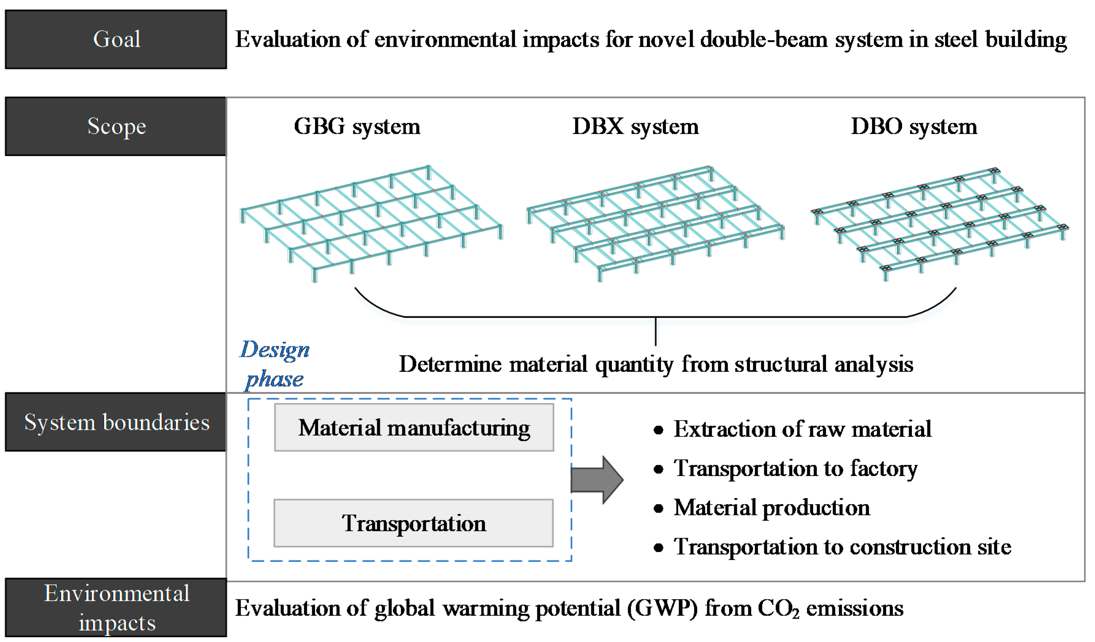
2. Life Cycle Assessment in Design Phase

2.1. Framework and Objectives

The LCA framework is a known tool for quantifying and assessing the potential environmental impacts of resources used during the entire life cycle of a product or a system, from the manufacturing process to use and maintenance [30,31]. Based on ISO 14040 (International Organization for Standardization) [30], the LCA framework is divided into four phases; (i) goal and scope definition: determining the goals and target of LCA, including setting the scope of data collection (i.e., system boundary) and framework, (ii) inventory analysis: collecting input resource and output waste data necessary to analyze the goals with respect to the target, (iii) impact assessment: analyzing and assessing the impact on the environmental load with the collected data, and (iv) interpretation: performing a quantitative evaluation on the environmental impact based on the impact assessment results. The life cycle stages of a building include material manufacturing, transportation, construction, operation, and demolition. In this study, the system boundary was limited to material manufacturing and transportation to assess environmental impacts resulting from the material quantity reduction in the design phase of a building.
Figure 1 shows the LCA framework for the environmental impact assessment of a steel building in the design phase. The objective of the LCA in this study is to evaluate the embodied CO2 emissions due to reductions in the material quantity of buildings to which the double-beam system is applied. Since the LCA is applied to buildings that meet the design code, the question of whether or not to satisfy the design code was set as a pre-boundary condition before the LCA. The double-beam system was designed to reduce the material quantity of structural elements with respect to vertical loads by installing two steel beams in one direction to decrease the moment demand. The connections between the double-beam and girder are bolted connections, so it has the advantage of increasing the in-situ constructability. However, when the gravity load increases, the effect on the reduction in material quantity decreases as the moment demand of the double-beam increases. The concrete panel installed around the column constraints the beam-end of the double-beam and play a part in reducing the moment demand by inducing a negative moment at the ends. So, this favorable structural characteristic has an environmental advantage of reducing the embodied CO2 emissions due to a decrease in the moment demand even under high gravity loads. As the rotational constraints greatly affect the structural behavior, research on their impact on environmental performance can extend the perspective of LCA. In this regard, this study investigates the effects on the reduction in material quantity induced by the rotational constraint of the concrete panel in the double-beam system through LCA procedure.
The double-beam system was divided into a double-beam system without a concrete panel (DBX) and a double-beam system with a concrete panel (DBO). The general beam-girder (GBG) system is a reference system for evaluating the quantity reduction in a steel building to which the double-beam system is applied. Through a 3D frame analysis, the material quantity for steel and concrete that meets the design conditions set as the pre-boundary conditions of the LCA was derived. Then, the embodied CO2 emission occurring in the material manufacturing and transportation stages set as the system boundary of the design phase was analyzed. Finally, the global warming potential (GWP) was evaluated based on the embodied CO2 emissions for each structural system.

2.2. Environmental Impacts Analysis

The environmental impacts of buildings applied with different structural systems are assessed in terms of embodied CO2 emissions. The life cycle carbon emissions analysis (LCCO2A) is a fundamental tool for assessing the environmental impacts of buildings. The life cycle CO2 emissions from buildings can be classified into embodied, operational, and demolition CO2 emissions [32]. Of these, the embodied CO2 emission signifies the total amount of CO2 generated from the collection of resources required for the construction of the building to the material transportation. The embodied CO2 emissions vary depending on the material quantities required for the construction of structural elements. Therefore, it can be said to be suitable for use in assessing the environmental impact of the structural system in the design phase.
The embodied CO2 emissions of materials that constitute a building are calculated using Equation (1), while the embodied CO2 emissions for each material, such as concrete or steel, are calculated by Equation (2). The embodied CO2 emissions include carbon emission (i.e., fossil carbon emission) generated from the material production, and carbon emission (i.e., process carbon emission) from the chemical reactions that occur during the manufacturing process. With the use of carbon emissions databases, the embodied CO2 emissions can be directly calculated from the material quantity of structural elements through Equation (3). ICE-DATA v2.0 (Inventory of Carbon & Energy (ICE) database), 0.141 kgCO2-eq/kg was used as a ρ value for the concrete material, and 1.42 kgCO2-eq/kg for the steel material [24,33].
CO 2 ,   E m b o d i e d = i CO 2 ,   E m b o d i e d ,   i
CO 2 ,   E m b o d i e d , i = j CO 2 ,   E m b o d i e d ,   i ,   j
CO 2 ,   E m b o d i e d ,   i = ρ i m i
where CO2, Embodied represents the embodied CO2 emission of whole building materials, CO2, Embodied, i represents the embodied CO2 emission of the i-th building material, CO2, Embodied, i, j represents the CO2 emission during the j-th phase in the i-th building material, ρi is the carbon-equivalent emission value for the i-th building material (kgCO2-eq/kg), and mi the mass of the i-th building material (kg).
Through the life cycle impact assessment (LCIA), carbon emission results derived from the material quantity of buildings applied with different structural systems can be converted into environmental impacts. The LCIA consists of four steps: classification, characterization, normalization, and weighting. In this study, classification and characterization, the mandatory processes of the LCIA, were taken into consideration. Classification is the process of connecting the environmental impact that a specific emission gives; carbon emission is a factor influencing the GWP. Characterization is the process of quantifying the environmental impact caused by a specific emission. The characterization factor is used as a means of quantification, and the environmental impact on the GWP can be estimated through Equation (4).
GWP = CO 2 ,   E m b o d i e d × CF
where CF is the characterization factor for the GWP (1.00 kgCO2-eq/kg from IPCC 2013 [34]).

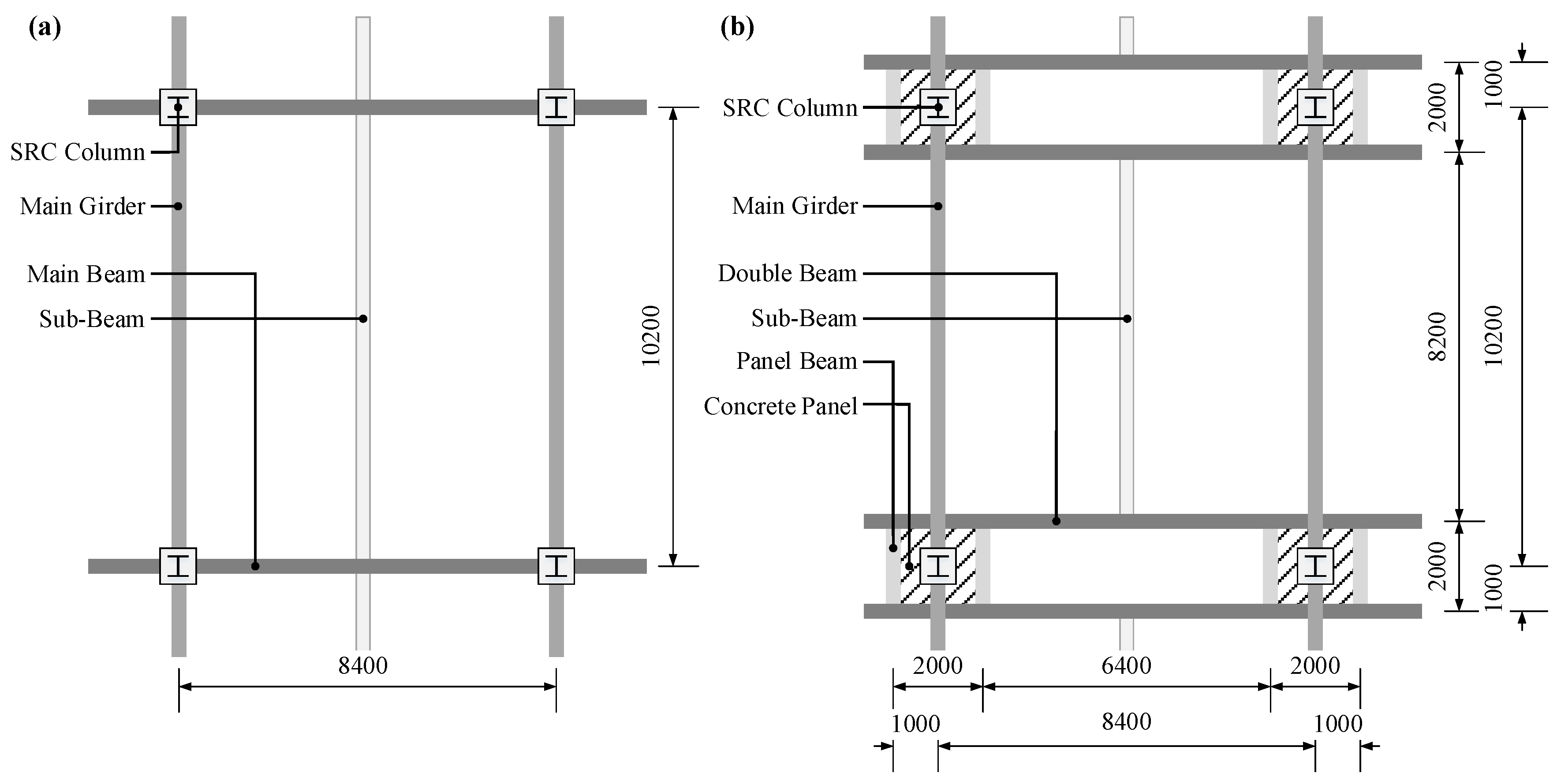
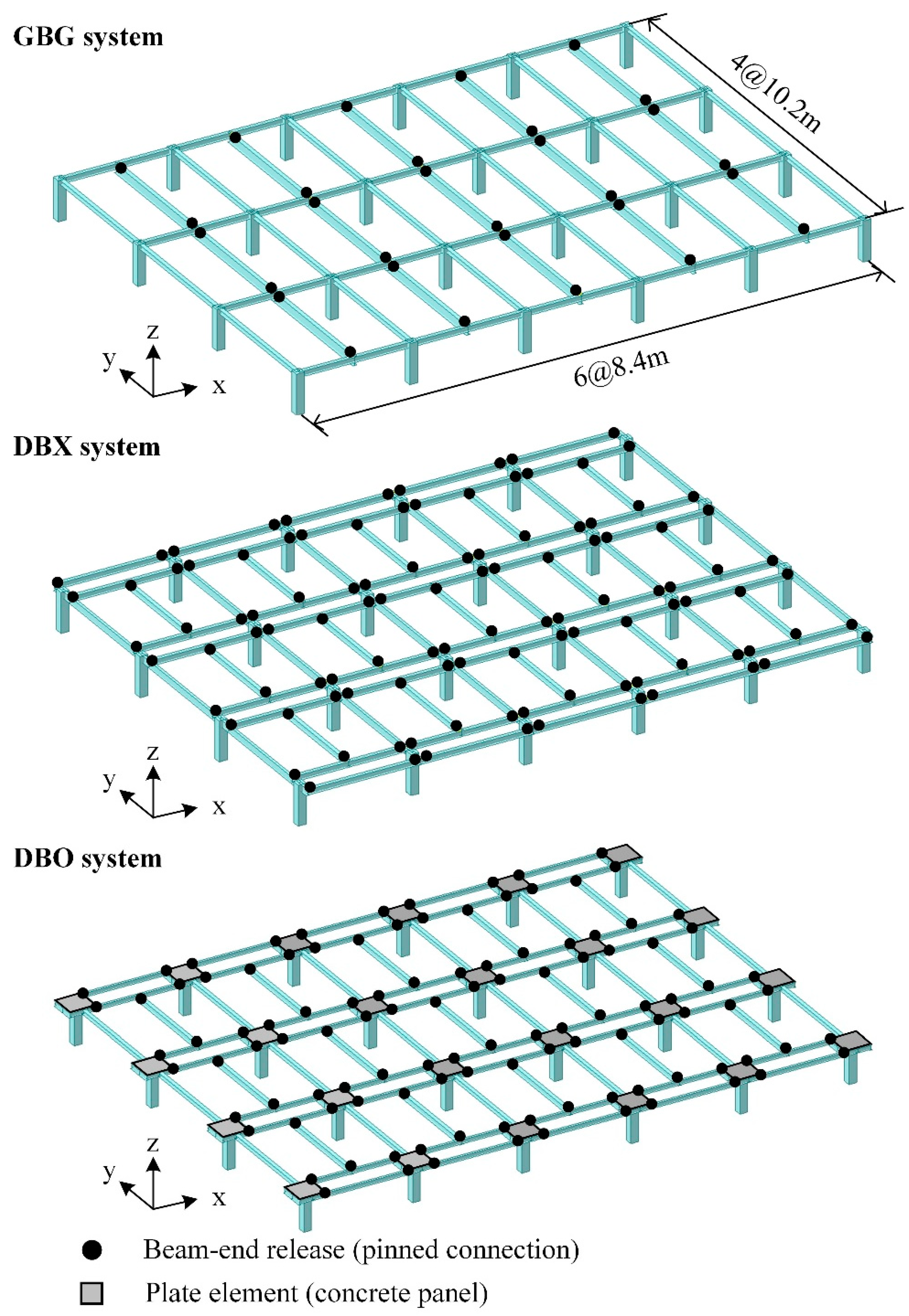
3. Structural Design of Novel Double-Beam Floor System

This study aims to analyze the environmental impacts of embodied CO2 emissions arising from structural systems applied to underground structures during top-down construction. While it is generally known that the material strengths affect embodied CO2 emissions [35], the yield strength of steel was used into 325 MPa and the compressive strength of concrete into 27 MPa to compare embodied CO2 emissions due to differences in structural systems. The process of determining the moment demand for each structural element due to gravity loads is important in structural design, and the quantity that meets the design conditions can be calculated through the process. In this chapter, after examining the considerations and processes in structural designs according to the presence of the beam-end concrete panel in the double-beam system, the effect on the reduction in material quantity in structural elements is analyzed.

3.1. Description of Structural Systems

The double-beam system consists of concrete-filled steel tube (CFT) columns, steel beams, and concrete panels, and it has a structural advantage that can reduce the cross-section of the steel beams by installing two beams (double-beam) in one direction. The connections between the double-beam and the main girder correspond to the beam–column connection of the general beam-girder (GBG) system, and the bolted connections are used to enhance constructability in the double-beam system. Figure 2 shows the outline of the steel building to which the GBG and DBO are applied. A unit parking space for one vehicle must be secured at least 2.5 m × 5.0 m, according to the Korean Design Standard (KDS) [36]. The dimension of the frame was determined to be 8.4 m × 10.2 m to accommodate the parking space of six vehicles assuming the width of the column to be 0.7 m. The GBG system is a reference system to compare the environmental impact resulting from the reduction in the material quantity of the double-beam system. The DBX system is a case in which there is no concrete panel in Figure 2b.
The double-beam system applied to the underground structures was developed to improve constructability and reduce structural material quantities. However, preliminary research found that as the live load increases, the effect of reduction in the structural material quantity is insignificant, and there is almost no advantage of the material quantity reduction, especially at a high live load of 8.0 kN/m2 or more. Therefore, by reinforcing the beam-end concrete panel to reduce the moment demand and material quantity of the double-beam, the double-beam system can have environmental competitiveness towards buildings with high gravity loads. The dead loads are summarized in Table 1, including the slab thickness and finishing material. In general, the slab is constructed as a deck plate during the top-down construction, but the dead load for the RC slab was calculated to evaluate the gravity load conservatively. The live loads were classified into five categories according to ASCE 7–16 (American Society of Civil Engineers) [37], considering the usages of the underground space summarized in Table 1. L1 is for office usage, and L2 to L4 indicate parking lot usage. In Korea, the live load was designed to be 8.0 kN/m2 for the underground structure of the knowledge industrial center, and the knowledge industrial center was set to H1. The frame analysis was conducted on a total of 15 models for three systems according to the five live load conditions.
The analysis of the load flow of each system against the gravity load under the assumption of a one-way slab reveals that the main beam of the GBG is subjected to a concentrated load at the center from the two sub-beams. For the GBG, the moment demand of the main beam, MG, for an arbitrary floor load, Wf, is represented by Equation (5).
M G = P 1 L 4 = L 4 ( W f A 1 )
where P1 is the concentrated load (kN) at the center of the main beam from the sub-beam, L is the length of the main beam (8.4 m), Wf is the floor load (kN/m2) due to the gravity load, and A1 is the tributary area of the main beam, which is ((8.4 m/2) × 10.2 m)/2 × 2EA = 42.84 m2.
On the other hand, the double-beam is subjected to a concentrated load at the center from the sub-beam and a uniformly distributed load from the slab. The moment demand of the double-beam, MD, for an arbitrary floor load, Wf, is calculated using Equation (6).
M D = P 2 L 4 + ω 2 L 2 8 = L 4 ( W f A 2 ) + L 2 8 ( W f L 2 )
where P2 is the concentrated load (kN) at the center of the double-beam from the sub-beam, L is the length of the double beam (8.4 m), ω2 is the uniformly distributed load (kN/m) from the slab, A2 is the tributary area of the double-beam for the sub-beam, which is ((8.4 m/2) × 8.2 m)/2 × 1EA = 17.22 m2, and L2 is the half-width of the concrete panel, which is 2.0 m/2 = 1.0 m.
From Equations (5) and (6), MG and MD are calculated at MG = 90.0 Wf, and MD = 45.0 Wf = 0.5 MG, respectively, and the moment demand of the double-beam is equivalent to half of the main beam under the same boundary conditions. In other words, the double-beam system can realize a reduction in material quantity compared to the GBG system under the same loading gravity load since the cross-section of the double-beam that satisfies the flexural design can be smaller than that of the main beam of the GBG. In addition, the cross-section of the sub-beam can be reduced in the double-beam system compared to the GBG system due to the decrease in the tributary area of the sub-beam. The reduction in the moment demand in the double-beam system is possible by increasing the rotational constraint, which can be implemented by reinforcing concrete panels at both ends of the double-beam. In the next section, we analyzed the rotational constraint of the concrete panels and their effect on the moment demand.

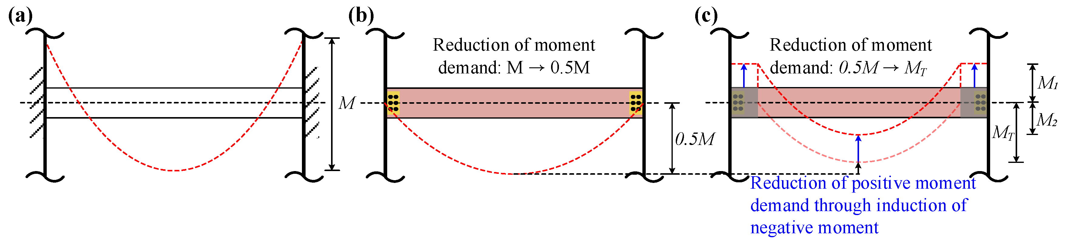
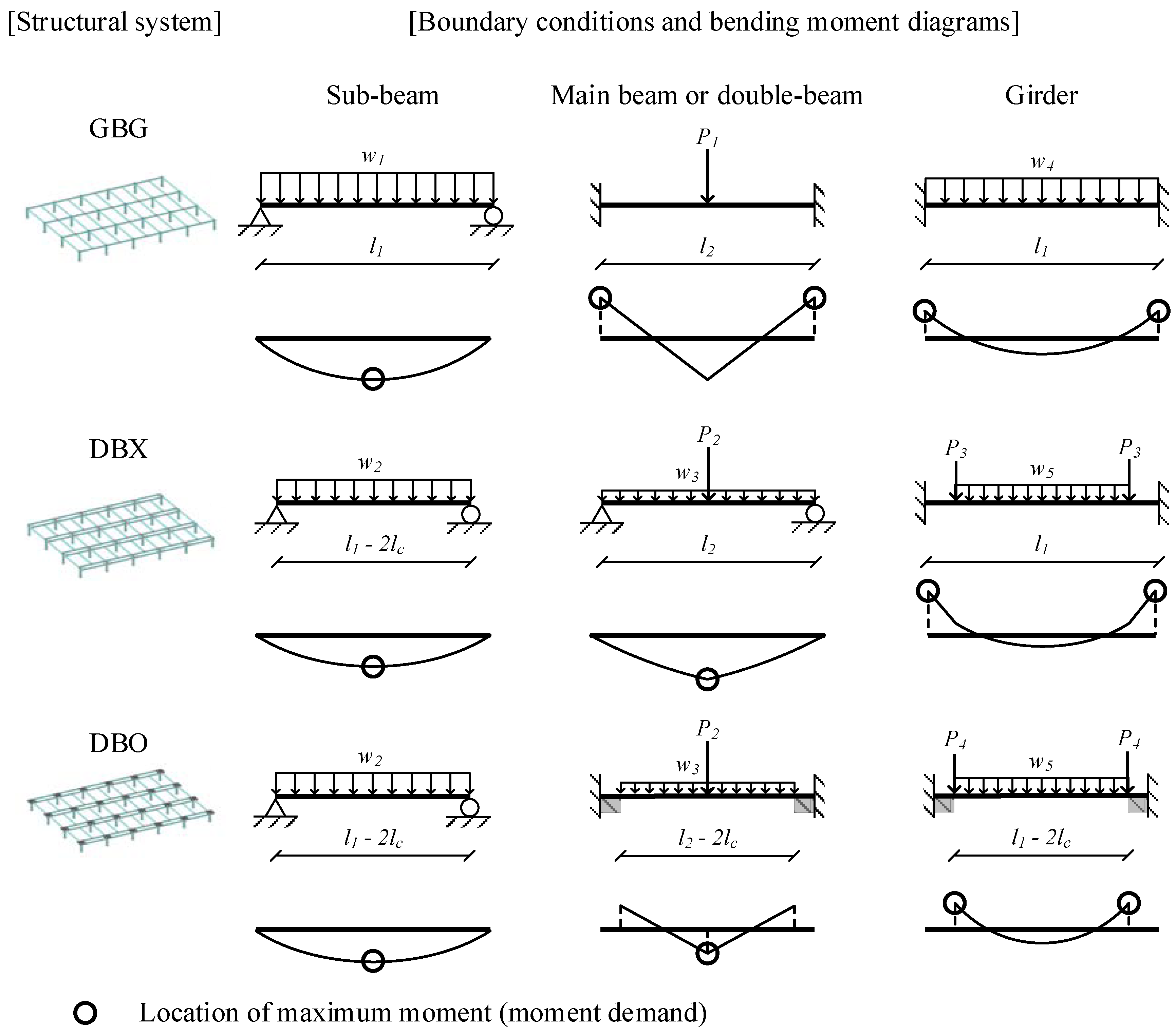
3.2. Rotational Constraint Effect on Moment Demand

The connection of the GBG system is generally designed as an idealized rigid connection. In this case, the moment diagram of the main beam can be ideally thought to be when both ends are in a fixed-end condition, as shown in Figure 3a. Meanwhile, for the DBX without the concrete panel, since rotational constraint cannot be expected at both ends of the double-beam, the double-beam can be considered to be a simple beam where the flexural moment is zero at both ends, as shown in Figure 3b. For the DBO system reinforced with concrete panels, both ends can be considered to be in a fixed end condition if the rotational constraint of the column zone is sufficiently large. The rotational constraint effect induced by the concrete panel can reduce the positive moment demand of the double-beam due to negative moments generated at both ends, together with the reduction in the effective length of the double-beam, as shown in Figure 3c. Therefore, if sufficient rotational constraint is secured at both ends of the double-beam, economical design can be achieved by reducing the moment demand for the gravity load of the double-beam.
In the GBG, DBX, and DBO systems, the moment demands of gravity loads were analyzed to investigate the effects of rotational constraint on the moment demand of the double-beam. In the GBG system, since both ends are in a fixed end condition, and a concentrated load is applied at its center, the positive and negative moments are equal to 0.5 MG. In the DBX system, the magnitude of the positive moment of the double-beam is 0.5 MG, which is the same as the positive and negative moments of the main beam in the GBG system. So, the quantity of structural steel that satisfies the design conditions is larger in the DBX system than in the GBG system since the double-beam of the DBX system has the same moment demand as that of the main beam in the GBG system. For the DBO system, the effective length of the double-beam (Le = LL2 = 6.4 m) is substituted into L in Equation (6); the moment demand of the double-beam MD2 is 32.67 Wf, which is about 36% of the moment demand of the main beam MG in the GBG system. Therefore, by securing sufficient rotational constraints at both ends of the double-beam with concrete panels, the moment demand of the double-beam is significantly reduced, so that the steel quantity can be drastically decreased. In addition, as the depth of the steel beam decreases, cost savings are realized through the floor height reduction in the underground structures.

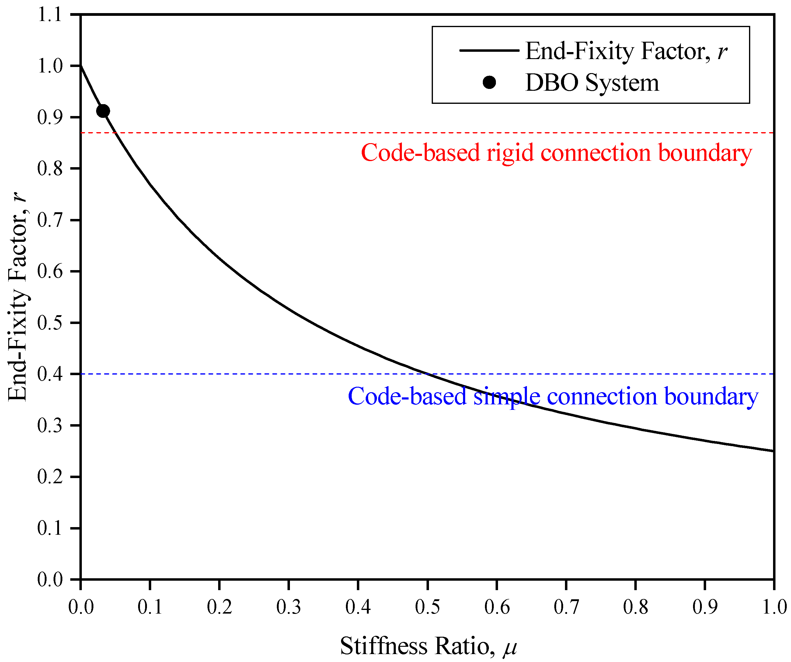
3.3. Structural Modeling Considering Rotational Constraint

The rotational constraint induced by the concrete panel is a factor that significantly influences the moment demand of the double-beam in the DBO system. Figure 4 shows the results of the quantitative analysis of the rotational constraint of the DBO system through experiments. The stiffness ratio (μ) defined as Equation (7) corresponding to the x-axis is the ratio of the rotational stiffness of the connection to the flexural stiffness of the double-beam. The end-fixity factor (r) defined as Equation (8) corresponding to the y-axis is the ratio of the fixed end moment to the negative moment generated at the double-beam end. The stiffness ratio and end-fixity factor of a simple connection based on ANSI/AISC 360 (American National Standards Institute/American Institute of Steel Construction) [38] are 0.500 and 0.400, respectively. In the case of a rigid connection, the stiffness ratio and end-fixity factor are 0.050 and 0.870, respectively. The stiffness ratio and the end-fixity factor of the DBO system are 0.032 and 0.912, respectively, so the DBO system can then be classified as a rigid connection presented in the current code.
μ = ( E I / L ) k r o t
r = M F E M
where μ is the connection stiffness ratio, E and I are the elastic modulus (205,000 MPa) and the moment of inertia (m4) of the double-beam, krot is the connection rotational stiffness induced by the beam-end concrete panel (kNm/rad), r is the end-fixity factor, M is the negative moment at the beam-end (kNm), and FEM is the fixed-end moment generated at the fixed-end (kNm).
The rotational constraint by the concrete panel affects the connection in both directions. Therefore, it is more practical to model the concrete panel as a plate element in both directions rather than as a rotational spring in the direction of a single axis. In the DBO system, the rotational stiffness of the connection for the double-beam is krot, and it can be calculated from the stiffness ratio (μ) and the rotational stiffness of the double-beam (EI/L) through Equation (7). The rotational stiffness Kp of the plate element is defined as in Equation (9) based on the Kirchhoff–Love plate theory. Given that Kp and krot are the same, the elastic modulus Ep of the concrete panel required to model the rotational constraint as a plate element can be calculated using Equation (10). Table 2 summarizes the elastic modulus of the concrete panel calculated from Equation (10) for the models to which the DBO system is applied. The moment of inertia (I) required to calculate the elastic modulus of the concrete panel can be obtained from the cross-section of the double-beam summarized in Table 2. The cross-section of the double-beam in each model of the DBO system was determined through frame analysis.
K p = E p t 3 12 ( 1 ν 2 )
E p = E I / L μ 12 ( 1 ν 2 ) t 3
where Kp is the flexural stiffness (kNm/rad), Ep is the elastic modulus of the concrete panel (MPa), t is the thickness of the concrete panel (0.4 m), and ν is the Poisson’s ratio of concrete (0.15).
Frame analysis was performed using MIDAS-Gen [39], and the five live loads summarized in Table 1 were applied to three structural systems. For example, GBGL1 refers to a model with live load condition L1 (=2.5 kN/m2) applied to the GBG system. Figure 5 shows the standard model to which each structural system is applied. The dimensions of the standard model are 6@8.4 m (=50.4 m) × 4@10.2 m (40.8 m) based on the dimensions summarized in Figure 2. In Figure 5, the solid circle is a pinned connection, and the black square represents the concrete panel. The beam–column connection of the GBG system was modeled as a rigid connection. In the DBX system, the main girder and column were modeled as a rigid connection, while the double-beam and main girder were modeled as a pinned connection. In the case of the DBO system, a plate element 400 mm thick and 2.0 m wide, with Ep values summarized in Table 2, was added to the column zone in the DBX system. A series of frame analysis was carried out in consideration of the boundary conditions of each model for one typical floor. The member forces were calculated, and the steel sections that satisfy the design code of ANSI/AISC 360 [38] were then summarized in Table 2. The ratio of the required strength and design strength determined by the moment demand was set to 0.80~0.85.

4. Results and Discussions

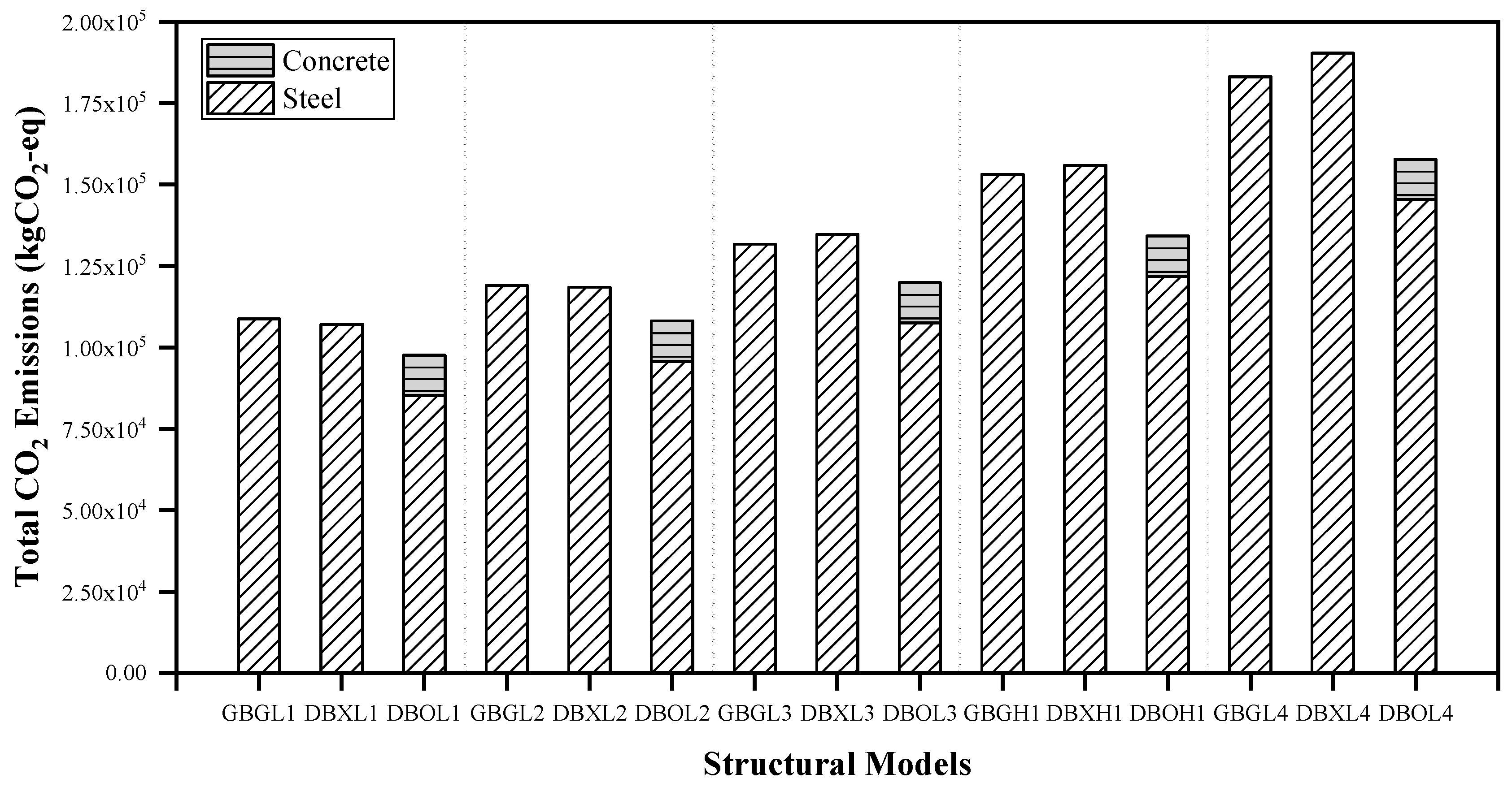
4.1. CO2 Emissions Based on Material Quantity from Structural Analysis

Figure 6 shows a comparison between the bending moment diagram of the structural elements obtained from the frame analysis in each system compared with the boundary conditions. The points marked with circles in Figure 6 represent the location of the maximum moment (i.e., moment demand) that determine the cross-section of the structural elements, and detailed values are summarized in Table 3. Since the magnitude of the moment demand in beam elements is an important factor determining the cross-section of the elements, it is directly related to the steel quantity involved in the calculation of the embodied CO2 emissions. Therefore, differences in moment demand arising from beam elements in each system were analyzed in this study.
First, in all systems, the sub-beam has the boundary condition of a simple beam subjected to a uniformly distributed load. Since the sub-beams of the DBX system and the DBO system have the same loading and boundary conditions, the moment demand of the sub-beam is the same in both systems, as summarized in Table 3. In addition, the moment demand of the sub-beam in both double-beam systems is 36% smaller than that in the GBG system due to the smaller tributary area and shorter length of the sub-beam. In other words, the double-beam system has a structural advantage that can reduce the material quantity of the sub-beam compared to the GBG system regardless of the presence of concrete panels.
Second, the main beam of the GBG system and the double-beam of the DBX system are designed as the same cross-sections as summarized in Table 2 because they have similar moment demands. On the other hand, the beam-end constraints by the concrete panel can significantly reduce the material quantity of the double-beam as the moment demand of the double-beam in the DBO system decreases by 63% compared to the moment demand for the main beam of the GBG system. In relation to the moment demand for girder, the DBX system is 59% larger than the GBG system, whereas the DBO system is 40% smaller than the GBG system. As the concrete panel reduces the effective length of the girder as well as the beam-end constraints of the double-beam, the moment demand of girder in the DBO system is smaller than that of the GBG system. Therefore, the concrete panel installed at the end of the double-beam reduces the moment demand of the double-beam and the girder in the double-beam system, further reducing the material quantity of the two structural elements compared to the GBG system.
Table 4 summarizes the material quantity that meets the design conditions from the cross-sectional information of structural elements for each system. The quantity of concrete panels is included in the DBO system. The steel quantity of the DBX system is slightly smaller than that of the GBG system when the live load is lower than 4.0 kN/m2, but the difference in quantity between the two systems is reversed when the live load is 6.0 kN/m2 or more. Therefore, the DBO system reinforced with concrete panels was developed to reduce the material quantities under high gravity loads, and it can be confirmed that the steel quantity of the DBO system is the smallest at all live load levels. This is because the moment demand for structural elements in the DBO system is lower than that of the other two systems, and thus the steel quantity that meets the design conditions is the smallest.
Figure 7 shows a comparison between embodied CO2 emissions that meet the design conditions on the live load levels for each structural system. When the live load is 6.0 kN/m2 or more, the embodied CO2 emissions of the GBG system become lower than those of the DBX system, as shown in Figure 7. Accordingly, as the gravity load increases, a difference in the embodied CO2 emissions between the GBG system and the DBX system also tends to increase. The reason why the embodied CO2 emissions of the DBX system further increase compared to that of the GBG system is that the embodied CO2 emissions associated with the double-beam greatly increase in the DBX system as the gravity load increases. On the other hand, the DBO system exhibits lower embodied CO2 emissions compared to the GBG system under all gravity loads, and the difference in the embodied CO2 emissions between the two systems tends to increase as the gravity load increases. The biggest reason for a further reduction in the embodied CO2 emissions in the DBO system than in the other two systems is that the embodied CO2 emissions decrease in the double-beam, and the second largest contributor to the reduction is the decrease in the embodied CO2 emissions for the girder. Therefore, it can be said that the installation of concrete panels is effective at reducing embodied CO2 emissions associated with steel members as it reduces the effective length of the double-beam and girders and decreases the moment demand due to the induction of negative moment at the end of the double-beam.

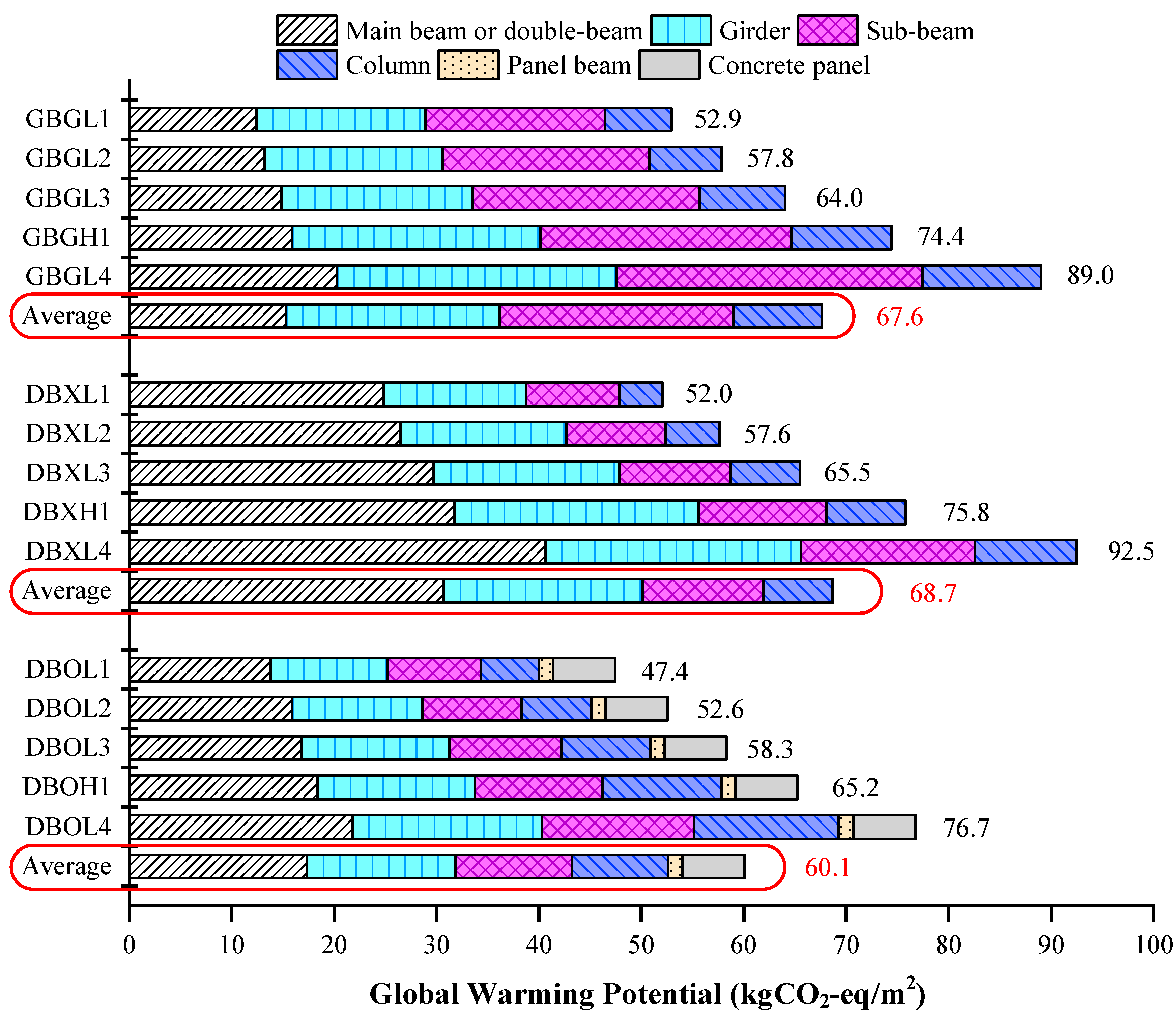
4.2. Environmental Impacts Assessment

In this study, the environmental impacts of each structural system were analyzed in terms of a GWP normalized to the floor area from the embodied CO2 emissions per floor. The operational phase serves as a significant contributor to total CO2 emissions of buildings, but the architectural configuration influences environmental impacts more in the operational phase than on the structural elements [40]. Therefore, in order to compare the environmental impacts due to the application of different structural systems, it is desirable to evaluate the GWP calculated as the quantity of the structural elements in the structural design phase.
Figure 8 shows the GWP for each structural model according to the structural elements. For example, when the live load is 2.5 kN/m2 (L1), the GWP of the GBGL1 is evaluated as 52.9 kgCO2-eq/m2 in the design phase. If the double-beam systems are applied under the same design load, the DBX system reduces GWP by 0.9 kgCO2-eq/m2, and the DBO system reduces GWP by 4.5 kgCO2-eq/m2. When the live load is lower than 4.0 kN/m2 (L2), the GWP of the DBX system is lower than that of the GBG system. However, as the gravity load increases, the GWP of the DBX system becomes higher than that of the GBG system, and the environmental performance of the DBX system is lower than that of the GBG system under high loads. On average, the GWP of the DBX system is higher than that of the GBG system, so it can be said that the DBX system is inferior to the GBG system in terms of environmental performance. On the other hand, the DBO system exhibits lower GWP compared to the GBG system at all load levels, and the difference tends to increase with increasing loads. In the DBX system, the GWP increases greatly due to an increase in the material quantity of the double-beam. In contrast, the GWP of the double-beam in the DBO system does not increase significantly even under high loads due to the beam-end rotational constraint induced by the concrete panel.
The GWP results of the three structural systems under low gravity loads (6.0 kN/m2 or less) and high gravity loads (8.0 kN/m2 or more) are represented in Figure 9. The GWP values of the GBG system and the DBX system are similar under the low gravity load, but the GWP value of the DBX system is 3% higher than that of the GBG system under the high gravity load. The DBX system can further decrease the material quantity of the main girder and sub-beam compared to the GBG system, thereby reducing the contribution of the structural elements to the GWP. However, in the DBX system, an increase in the material quantity of the double-beam due to the increase in the gravity load is governed in the increase in the GWP. Therefore, an increase in the material quantity of the double-beam acts as a significant cause of deterioration of the environmental performance of the DBX system.
The DBO system exhibits 9.4% lower GWP than the GBG system under the low gravity load, and 13.1% lower GWP than the GBG system under the high gravity load. As the gravity load increases, the environmental performance of the DBO system is higher than that of the GBG system. It is understood that in the DBO system, the GWP increases due to the addition of concrete panels, but the total GWP decreases as the addition of concrete panels results in a reduction in the GWP of the double-beam. The DBO system is capable of enhancing the environmental caused by a decrease in the GWP of the double-beam due to the beam-end rotational constraint while maintaining the effect of reducing the GWP of the sub-beam and main girder in the DBX system. Therefore, the DBO system has higher environmental performance than the existing GBG system, and the difference in the environmental performance between them is more considerable under high gravity loads.

5. Conclusions

This study aims to analyze the environmental impacts of a steel double-beam floor system applied to underground structures in the structural design phase. The steel double-beam system was divided into DBX (i.e., without concrete panel) and DBO (i.e., with concrete panel) systems according to the presence of concrete panels for beam-end constraint, and the GBG system was set as a reference system to compare the environmental impacts. The live loads were classified into five categories in consideration of the usage of underground space, and material quantities that meet the design conditions were derived from structural analysis. In addition, the LCA methodology was used to evaluate the environmental performance of each structural system in the design phase. The following conclusions were derived from this study.
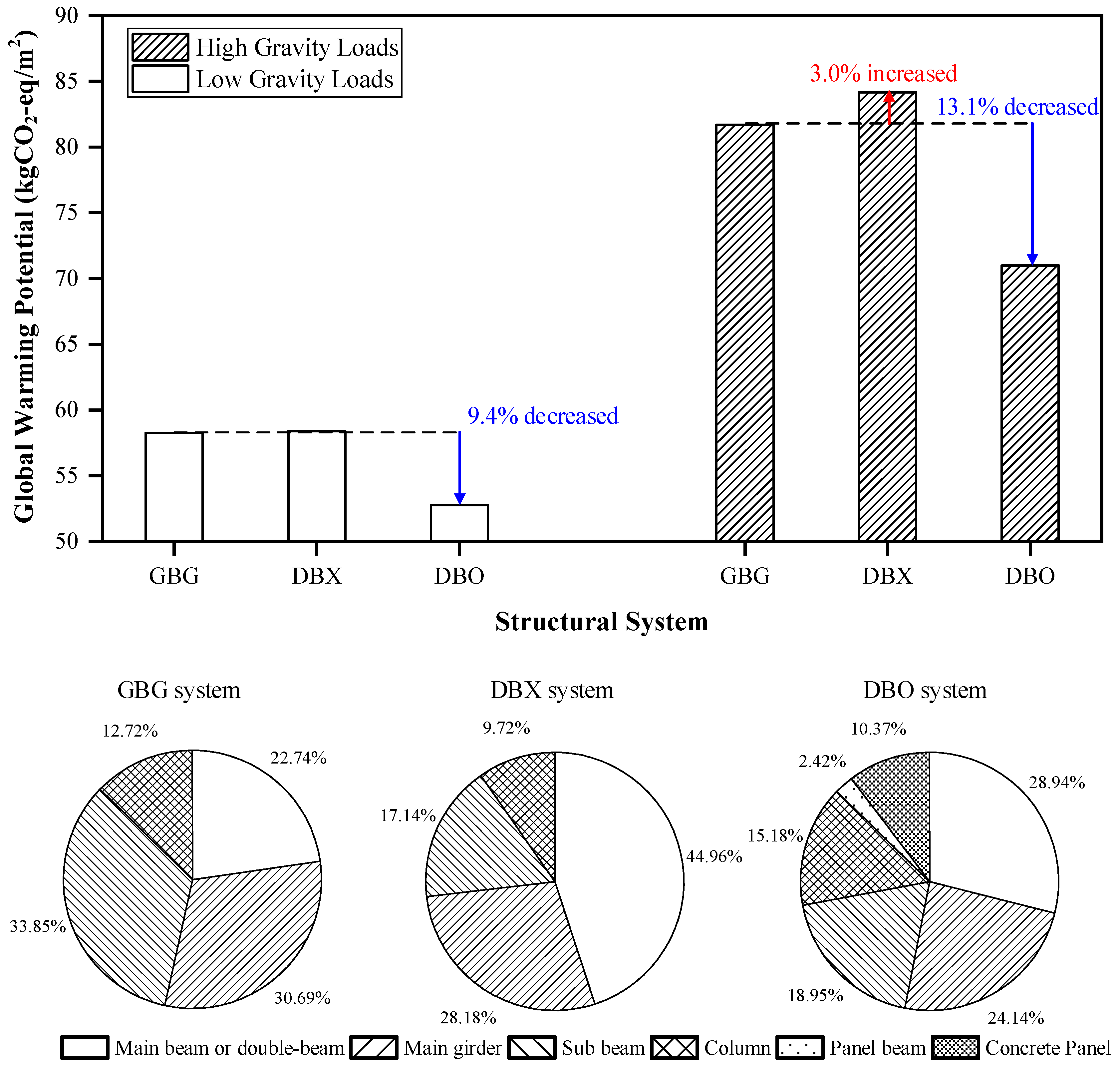
  • The global warming potential (GWP) of the DBX system is similar to that of the GBG system at low gravity loads where the live load is less than 6.0 kN/m2. However, when the live load exceeds 6.0 kN/m2, the GWP of the DBX system increases compared to the GBG system, resulting in lower environmental performance. Although the DBX system can reduce the material quantity of girder or sub-beam more than the GBG system, an increase in the material quantity of the double-beam is more governed in the increase in the GWP than a reduction in the quantity of the two elements.
  • The DBO system exhibits a lower GWP than the GBG system under all gravity loads, and the differences in GWP between the DBO and GBG systems increase by up to 13.8% as the gravity load increases. Therefore, it can be said that the DBO system has the highest environmental performance under high gravity loads. The analysis found that in addition to the quantity reduction effects of the girder and sub-beam of the DBX system, the quantity reduction in the double-beam due to the installation of concrete panels significantly contributed to reducing the GWP.
  • The contributions of the double-beam to the GWP in the DBX system are 45.0% on average, accounting for about half of the total GWP, while these contributions in the DBO system are 28.9% on average. The results showed that the rotational constraint effect induced by the concrete panel significantly contributed to the reduction in GWP by decreasing the design moment of the double-beam due to the structural advantages such as the reduction in the effective length and the induction of the negative moment.
The steel double-beam floor system poses a disadvantage in that the environmental performance decreases at high gravity loads. However, the addition of concrete panels makes it possible to increase the environmental performance due to the material quantity reduction in the double-beam even under high gravity loads. Therefore, the steel double-beam floor system reinforced with concrete panels can be a candidate for environmentally friendly structural systems in the structural design of underground structures, in downtown areas, requiring high gravity loads.

Author Contributions

Conceptualization, I.C. and J.K.; formal analysis, I.C.; funding acquisition, J.K.; methodology, I.C. and J.K.; project administration, J.K.; investigation, I.C. and D.K.; software, I.C. and D.K.; supervision, J.K.; validation, I.C., J.K. and D.K.; visualization, I.C., J.K. and D.K.; writing—original draft, I.C.; writing—review and editing, I.C. and J.K. All authors have read and agreed to the published version of the manuscript.

Funding

This research was supported by a grant (NRF-2018R1A2B6006958) from the National Research Foundation of Korea (NRF) funded by the Korean Ministry of Science and ICT (MSIT) and by a grant (20194010201850) from the Korea Institute of Energy Technology Evaluation and Planning (KETEP) and the Korean Ministry of Trade, Industry and Energy (MOTIE).

Conflicts of Interest

The authors declare no conflict of interest.

References

  1. IEA. 2019 Global Status Report for Buildings and Construction: Towards A Zero-Emission, Efficient and Resilient Buildings and Construction Sector; International Energy Agency: Paris, France, 2019. [Google Scholar]
  2. Park, H.S.; Jeong, K.; Hong, T.; Ban, C.; Koo, C.; Kim, J. The optimal photovoltaic system implementation strategy to achieve the national carbon emissions reduction target in 2030: Focused on educational facilities. Energy Build. 2016, 119, 101–110. [Google Scholar] [CrossRef]
  3. Jeong, K.; Hong, T.; Kim, J. Development of a CO2 emission benchmark for achieving the national CO2 emission reduction target by 2030. Energy Build. 2018, 158, 86–94. [Google Scholar] [CrossRef]
  4. Oh, J.; Hong, T.; Kim, H.; An, J.; Jeong, K.; Koo, C. Advanced Strategies for Net-Zero Energy Building: Focused on the Early Phase and Usage Phase of a Building’s Life Cycle. Sustainability 2017, 9, 2272. [Google Scholar] [CrossRef] [Green Version]
  5. IEA. CO2 Emissions from Fuel Combustion; International Energy Agency: Paris, France, 2019. [Google Scholar]
  6. Kaethner, S.; Burridge, J. Embodied CO2 of structural frames. Struct. Eng. 2012, 90, 33–40. [Google Scholar]
  7. Moncaster, A.M.; Pomponi, F.; Symons, K.E.; Guthrie, P.M. Why method matters: Temporal, spatial and physical variations in LCA and their impact on choice of structural system. Energy Build. 2018, 173, 389–398. [Google Scholar] [CrossRef]
  8. Valencia-Barba, Y.E.; Gómez-Soberón, J.M.; Gómez-Soberón, M.C.; López-Gayarre, F. An Epitome of Building Floor Systems by Means of LCA Criteria. Sustainability 2020, 12, 5442. [Google Scholar] [CrossRef]
  9. Moussavi Nadoushani, Z.S.; Akbarnezhad, A. Effects of structural system on the life cycle carbon footprint of buildings. Energy Build. 2015, 102, 337–346. [Google Scholar] [CrossRef]
  10. Motawa, I.A.; Price, A.D.F.; Sher, W. Modelling the implementation of technological innovations in construction. Int. J. Comput. Appl. Technol. 2004, 20, 78–89. [Google Scholar] [CrossRef]
  11. Rhim, H.-C.; Kim, K.-M.; Kim, S.-W. Development of an optimum pre-founded column system for top-down construction. J. Civ. Eng. Manag. 2012, 18, 735–743. [Google Scholar] [CrossRef] [Green Version]
  12. Hong, W.-K.; Kim, S.-I.; Park, S.-C.; Kim, J.-M.; Lee, S.-G.; Yoon, K.-J.; Kim, S.-K. Composite beam composed of steel and precast concrete (modularized hybrid system). Part IV: Application for multi-residential housing. Struct. Des. Tall Spec. Build. 2009, 19, 707–727. [Google Scholar] [CrossRef]
  13. Parra-Montesinos, G.J.; Dasgupta, P.; Goel, S.C. Development of connections between hybrid steel truss–FRC beams and RC columns for precast earthquake-resistant framed construction. Eng. Struct. 2005, 27, 1931–1941. [Google Scholar] [CrossRef]
  14. Campione, G.; Colajanni, P.; Monaco, A. Analytical evaluation of steel–concrete composite trussed beam shear capacity. Mater. Struct. 2016, 49, 3159–3176. [Google Scholar] [CrossRef]
  15. Amadio, C.; Macorini, L.; Sorgon, S.; Suraci, G. A novel hybrid system with rc-encased steel joists. Eur. J. Environ. Civ. Eng. 2011, 15, 1433–1463. [Google Scholar] [CrossRef]
  16. Lee, J.-M.; Kim, M.-J.; Lee, Y.-J.; Kim, S.-W.; Lee, J.-Y.; Kim, K.-H. Structural performance of composite double beam system. Adv. Struct. Eng. 2016, 19, 283–298. [Google Scholar] [CrossRef]
  17. Ju, Y.K.; Kim, J.-Y.; Kim, S.-D. Experimental Evaluation of New Concrete Encased Steel Composite Beam to Steel Column Joint. J. Struct. Eng. 2007, 133, 519–529. [Google Scholar] [CrossRef]
  18. Kinderis, T.; Daukšys, M.; Mockien, J. Research on the Efficiency of Composite Beam Application in Multi-Storey Buildings. Sustainability 2020, 12, 8328. [Google Scholar] [CrossRef]
  19. Khasreen, M.; Banfill, P.F.; Menzies, G. Life-Cycle Assessment and the Environmental Impact of Buildings: A Review. Sustainability 2009, 1, 674–701. [Google Scholar] [CrossRef]
  20. Cabeza, L.F.; Rincón, L.; Vilariño, V.; Pérez, G.; Castell, A. Life cycle assessment (LCA) and life cycle energy analysis (LCEA) of buildings and the building sector: A review. Renew. Sustain. Energy Rev. 2014, 29, 394–416. [Google Scholar] [CrossRef]
  21. Zeitz, A.; Griffin, C.T.; Dusicka, P. Comparing the embodied carbon and energy of a mass timber structure system to typical steel and concrete alternatives for parking garages. Energy Build. 2019, 199, 126–133. [Google Scholar] [CrossRef]
  22. Caruso, M.C.; Menna, C.; Asprone, D.; Prota, A. LCA-Based Comparison of the Environmental Impact of Different Structural Systems. Proc. IOP Conf. Ser. Mater. Sci. Eng. 2018, 442, 12010. [Google Scholar] [CrossRef] [Green Version]
  23. Cho, Y.S.; Kim, J.H.; Hong, S.U.; Kim, Y. LCA application in the optimum design of high rise steel structures. Renew. Sustain. Energy Rev. 2012, 16, 3146–3153. [Google Scholar] [CrossRef]
  24. Mavrokapnidis, D.; Mitropoulou, C.C.; Lagaros, N.D. Environmental assessment of cost optimized structural systems in tall buildings. J. Build. Eng. 2019, 24, 100730. [Google Scholar] [CrossRef] [Green Version]
  25. Trabucco, D.; Wood, A.; Vassart, O.; Popa, N. A Whole LCA of the Sustainable Aspects of Structural Systems in Tall Buildings. Int. J. High-Rise Build. 2016, 5, 71–86. [Google Scholar] [CrossRef] [Green Version]
  26. Skullestad, J.L.; Bohne, R.A.; Lohne, J. High-rise Timber Buildings as a Climate Change Mitigation Measure—A Comparative LCA of Structural System Alternatives. In Energy Procedia; Elsevier Ltd.: Amsterdam, The Netherlands, 2016; Volume 96, pp. 112–123. [Google Scholar]
  27. Chen, Z.; Gu, H.; Bergman, R.; Liang, S. Comparative Life-Cycle Assessment of a High-Rise Mass Timber Building with an Equivalent Reinforced Concrete Alternative Using the Athena Impact Estimator for Buildings. Sustainability 2020, 12, 4708. [Google Scholar] [CrossRef]
  28. Micheli, L.; Alipour, A.; Laflamme, S.; Sarkar, P. Performance-based design with life-cycle cost assessment for damping systems integrated in wind excited tall buildings. Eng. Struct. 2019, 195, 438–451. [Google Scholar] [CrossRef]
  29. Helal, J.; Stephan, A.; Crawford, R.H. The influence of structural design methods on the embodied greenhouse gas emissions of structural systems for tall buildings. Structures 2020, 24, 650–665. [Google Scholar] [CrossRef]
  30. ISO. ISO 14040: Environmental Management—Life Cycle Assessment—Principles and Framework; International Organization for Standardization: Geneva, Switzerland, 2006. [Google Scholar]
  31. ISO. ISO 14042: Environmental Management—Life Cycle Assessment—Life Cycle Impact Assessment; International Organization for Standardization: Geneva, Switzerland, 2000. [Google Scholar]
  32. Chau, C.K.; Leung, T.M.; Ng, W.Y. A review on life cycle assessment, life cycle energy assessment and life cycle carbon emissions assessment on buildings. Appl. Energy 2015, 143, 395–413. [Google Scholar] [CrossRef]
  33. Hammond, G.P.; Jones, C.I. Embodied energy and carbon in construction materials. In P. I. Civil Eng.—Energy; Thomas Telford Ltd.: London, UK, 2008; Volume 161, pp. 87–98. [Google Scholar]
  34. Myhre, G.; Shindell, D.; Bréon, F.M.; Collins, W.; Fuglestvedt, J.; Huang, J.; Koch, D.; Lamarque, J.F.; Lee, D.; Mendoza, B. Anthropogenic and Natural Radiative Forcing. In Climate Change 2013: The Physical Science Basis; Contribution of Working Group I to the Fifth Assessment Report of the Intergovernmental Panel on Climate Change; Cambridge University Press: Cambridge, UK, 2013; pp. 659–740. [Google Scholar]
  35. Ji, C.; Hong, T.; Park, H.S. Comparative analysis of decision-making methods for integrating cost and CO2 emission—Focus on building structural design—Focus. Energy Build. 2014, 72, 186–194. [Google Scholar] [CrossRef]
  36. MOLIT. Korean Design Standard; Ministry of Land, Infrastructure and Transport: Sejoing Special Governing City, Korea, 2016. (In Korean) [Google Scholar]
  37. ASCE. ASCE/SEI 7–6: Minimum Design Loads for Buildings and Other Structures; ASCE: Reston, VA, USA, 2016. [Google Scholar]
  38. AISC. Committee Specification for Structural Steel Buildings (ANSI/AISC 360-16); American Institute of Steel Construction: Chicago, IL, USA, 2016. [Google Scholar]
  39. MIDAS IT. MIDAS/GEN V8.5.5 Users Manual; MIDAS IT: Seongnam-si, Korea, 2017. [Google Scholar]
  40. Ji, C.; Hong, T.; Jeong, J.; Kim, J.; Lee, M.; Jeong, K. Establishing environmental benchmarks to determine the environmental performance of elementary school buildings using LCA. Energy Build. 2016, 127, 818–829. [Google Scholar] [CrossRef]
Figure 1. A framework of life cycle assessment in the design phase.
Sustainability 12 09193 g001
Figure 2. System outline in a steel building: (a) general beam-girder system (GBG); (b) double-beam system with concrete panel (unit in mm).
Sustainability 12 09193 g002
Figure 3. Moment diagram of the main beam or double-beam subjected to one-way gravity load: (a) general beam-girder system; (b) double-beam system without concrete panel; (c) double-beam system with concrete panel.
Sustainability 12 09193 g003
Figure 4. Normalized negative moment (end-fixity factor, r) and rotational stiffness (stiffness ratio, μ) in double-beam system induced by a beam-end concrete panel.
Sustainability 12 09193 g004
Figure 5. Three standard frame models with the different structural systems in the typical underground structures.
Sustainability 12 09193 g005
Figure 6. Boundary conditions and bending moment diagram of structural elements in the case study model according to applied structural systems.
Sustainability 12 09193 g006
Figure 7. Comparison of the embodied CO2 emissions comprised of steel and concrete with different structural systems and gravity loads.
Sustainability 12 09193 g007
Figure 8. Global warming potential for the structural elements in case study models.
Sustainability 12 09193 g008
Figure 9. Comparison of structural element contribution to the GWP (Global Warming Potential) for the different structural systems with the level of gravity load.
Sustainability 12 09193 g009
Table 1. Gravity load in steel building with various live load.
Load TypeMaterial/OccupancyUnit Load (kN/m3)Thickness (m)Floor Load (kN/m2)
Dead loadReinforced concrete240.153.60
Mortar200.040.80
Finishing200.040.80
Total 5.20
Live loadL1: Offices 2.50
L2: Passenger vehicles only 4.00
L3: Storage warehouses 6.00
H1: Knowledge industry center 8.00
L4: Heavy vehicles 12.00
Although not provided in ASCE 7–16 (American Society of Civil Engineers) [37], it is used as a live load for the underground structures of the knowledge industrial center in practice.
Table 2. Summary of structural elements depending on structural systems and live loads.
ModelLive Load (kN/m2)Cross-Section of Steel BeamElastic Modulus of Concrete Panel
(Ep, MPa)
Sub BeamGirderMain Beam
or
Double-Beam
GBGL12.5H-692 × 300 × 13 × 20H-310 × 305 × 15 × 16H-390 × 300 × 10 × 16-
GBGL24H-792 × 300 × 14 × 22H-350 × 350 × 12 × 19H-482 × 300 × 11 × 15-
GBGL36H-800 × 300 × 14 × 26H-394 × 398 × 11 × 18H-488 × 300 × 11 × 18-
GBGH18H-414 × 405 × 18 × 28H-792 × 300 × 14 × 22H-582 × 300 × 12 × 17-
GBGL412H-428 × 407 × 20 × 35H-708 × 302 × 15 × 28H-594 × 302 × 14 × 23-
DBXL12.5H-390 × 300 × 10 × 16H-506 × 201 × 11 × 19H-390 × 300 × 10 × 16-
DBXL24H-482 × 300 × 11 × 15H-606 × 201 × 12 × 20H-482 × 300 × 11 × 15-
DBXL36H-488 × 300 × 11 × 18H-612 × 202 × 13 × 23H-488 × 300 × 11 × 18-
DBXH18H-394 × 398 × 11 × 18H-600 × 190 × 16 × 35H-582 × 300 × 12 × 17-
DBXL412H-594 × 302 × 14 × 23H-700 × 300 × 13 × 24H-594 × 302 × 14 × 33-
DBOL12.5H-390 × 300 × 10 × 16H-294 × 302 × 12 × 12H-294 × 200 × 8 × 1220,731
DBOL24H-482 × 300 × 11 × 15H-300 × 300 × 10 × 15H-298 × 201 × 9 × 1424,400
DBOL36H-488 × 300 × 11 × 18H-390 × 300 × 10 × 16H-400 × 200 × 8 × 1343,480
DBOH18H-394 × 398 × 11 × 18H-482 × 300 × 11 × 15H-450 × 200 × 8 × 1361,459
DBOL412H-594 × 302 × 14 × 23H-582 × 300 × 12 × 17H-496 × 199 × 9 × 1476,870
Table 3. Summary of moment demand of structural elements from frame analysis.
Live Load (kN/m2)ModelsMoment Demand (kNm)
Sub BeamMain Beam or Double-BeamGirder
2.5GBGL1584.7489.5386.2
DBXL1372.0 (−36%) *482.5 (−1%)614.3 (59%)
DBOL1372.0 (−36%)181.2 (−63%)230.2 (−40%)
4GBGL2719.7600.5474.3
DBXL2457.5 (−36%)594.3 (−1%)755.5 (59%)
DBOL2457.5 (−36%)222.8 (−63%)283.2 (−40%)
6GBGL3897.3747.8595.1
DBXL3571.9 (−36%)740.7 (−1%)950.9 (59%)
DBOL3571.9 (−36%)278.6 (−63%)347.1 (−42%)
8GBGH11077.2896.5714.1
DBXH1688.8 (−36%)891.3 (−1%)1135.1 (59%)
DBOH1688.8 (−36%)336.2 (−62%)433.8 (−39%)
12GBGL41433.31196.4951.7
DBXL4917.8 (−36%)1188.7 (−1%)1516.2 (59%)
DBOL4917.8 (−36%)447 (−63%)539.6 (−43%)
* The percentages in parentheses are comparisons of moment demands with respect to the GBG system.
Table 4. Material quantities for construction per 1-story depending on the structural systems and live loads.
Structural SystemLive Load (kN/m2)Material Quantity (ton)
SteelConcrete
GBG2.576.60-
4.083.75-
6.092.72-
8.0107.76-
12.0128.88-
DBX2.575.34-
4.083.43-
6.094.83-
8.0109.77-
12.0133.99-
DBO2.559.9488.32
4.067.3488.32
6.075.6888.32
8.085.7088.32
12.0102.3588.32
Publisher’s Note: MDPI stays neutral with regard to jurisdictional claims in published maps and institutional affiliations.

