Article

Integrated Design Process for Modular Construction Projects to Reduce Rework

1
Institute of Engineering Research, Seoul National University, Gwanak-ro 1, Gwanak-gu, Seoul 08826, Korea
2
Department of Architectural Engineering, Dankook University, 152 Jukjeon-ro, Suji-gu, Yongin-si, Gyeonggi-do 16890, Korea
3
Department of Architecture and Architectural Engineering, Seoul National University, Gwanak-ro 1, Gwanak-gu, Seoul 08826, Korea
4
Technical Policy Research Team, Construction Engineer Policy Institute of Korea, Eonju-ro 650, Gangnam-gu, Seoul 06098, Korea
*
Author to whom correspondence should be addressed.
Sustainability 2020, 12(2), 530; https://doi.org/10.3390/su12020530
Submission received: 26 November 2019 / Revised: 22 December 2019 / Accepted: 7 January 2020 / Published: 10 January 2020
(This article belongs to the Special Issue Sustainable Construction Engineering and Management)

Abstract

:
In modular construction projects, unit production and onsite work are conducted concurrently, enabling shorter duration, lower cost, and improved quality. Because of the nature of the work, building design details should be determined early in the design phase, which requires information from participants. However, the design process for stick-built construction does not include such information, which leads to errors in design, such as omissions and conflicts of information from participants, causing reworking in the design phase. To reduce errors, an information flow should be identified representing when/what/how the information should be shared, and with whom. This paper proposes an integrated design process based on the information flow. To identify the flow, a precedence relationship between activities is represented using a dependency structure matrix (DSM). Then, the order of activities is rearranged using a partitioning algorithm. In this manner, unnecessary feedback and reverse information flow, which are related to errors, are reduced. Finally, the rearranged activities are proposed as an integrated design process. To validate the impact of the proposed process and methodology, interviews with experts were conducted. The validation results suggest that the project delivery method should also be considered in the early project phase in practical application.

1. Introduction

1.1. Background

The global construction industry suffers from various issues, such as labor shortage, low productivity, and environmental pollution [1,2]. Modular construction has gained attention as an effective approach for overcoming these problems because of its inherent benefits, such as improved productivity, shorter project duration, higher quality, and better occupational safety, owing to the controlled work environment of a factory [3,4,5,6]. Moreover, modular construction reduces waste by at least 70% in comparison with the industry average [7,8]. Thus, it is a more sustainable construction method [9,10,11].
In modular construction, a significant proportion of work in a project is conducted in a factory; the produced units are transported and then assembled onsite [5,11]. Because production and onsite work are conducted concurrently, project duration is reduced significantly [12]. Owing to the nature of the work, design details, such as unit installation and the connection method, should be determined early in the design phase to reduce errors such as omissions and conflicts and to start unit production and onsite work simultaneously based on the agreed design [13]. The decision-making process for finalizing the details requires integration of project participants in the early design phase; hence, the complexity of information flows between the participants increase in comparison with the conventional stick-built construction [13,14]. This complexity due to multilateral information exchange is a source for errors resulting from omissions and conflicts in the design, which in serious cases may even lead to redoing of the whole design process for rectification [13,15]. The feedback in the phase comprises communication between participants to include the information into the design. However, when the necessary participants for providing the information are not identified in the information flow before the phase, omissions or conflicts may occur when the work planning is established after the design phase, which may necessitate redoing of the whole design process for rectification [7,12,15,16,17,18,19,20,21]. For example, if the Road Traffic Act regulations of an area are not considered in a related design step, the size of units may need to be reworked for transportation, which can cause schedule and cost overruns.
In modular construction, the complexity involved makes identification of the information flows difficult [14]. To facilitate the integration of participants and identification of the information flows in the design phase of a modular project, an integrated design process is required to ensure that the project is managed considering the entire project process, including design, unit production, transportation, erection, and performance [22,23]. However, designs are still established based on conventional stick-built construction methods, which are unsuitable for modular construction, and lack of expertise and knowledge in the marketplace make it difficult to recognize the need for the integrated design process [18,22,24]. This causes uncertainty in the design process, leading to unnecessary and inappropriate feedback, which may affect project performance [12,18,19,25]. Consequently, the lower performance caused by reworking results in a negative stigma and barrier in the usage of modular construction [18].

1.2. Research Methodology

To address this problem, this paper proposes an integrated design process for modular construction projects based on identified information flows between activities in the design and work planning phases. The scope of the design process in this paper includes activities related to architectural, mechanical, structural, and electrical design of buildings and site analysis in the early design phase. It also includes selected activities from the related work planning phase that should be integrated into the design phase to reduce rework. This is because the inability to make changes onsite is the biggest barrier to using modular construction methods as it is costlier to rework than conventional construction methods [2,6,12,22,26,27]. To select the activities, major issues causing rework in modular construction are identified by analyzing daily reports of modular projects and reviewing existing literature. Then, strategies for mitigating reworking are identified by reviewing descriptions of the report and literatures. These strategies consist of activities that prevent the causes of errors, such as omissions or conflicts in design, which should be included to reduce rework in the field such as production and on-site if not considered at the design stage.
In suggesting an integrated design process, information flows and the relationship between activities are first identified based on the precedence relationship. Then, as a methodology to facilitate information flows, a dependency structure matrix (DSM) is derived. DSM has been used to represent complex processes in systems and also used to alleviate the complexity by representing the information flow using a matrix [28]. Based on the DSM, the sequence of activities is rearranged using the partitioning algorithm. Through this rearrangement, information flows are optimized to reduce feedback (or reverse information flows) between activities; the rearranged activity sequence can be used as the integrated planning process because the process provides information to project participants: (1) when the mitigation activities should be conducted, and (2) what information should be shared with whom in the design phase. Finally, the rearranged activities are briefly described. It is expected that adoption of the process outlined in this study will help reduce engineering rework (rework to rectify the design), as well as field rework (rework to rebuild or reassemble building components).

2. Preliminary Study

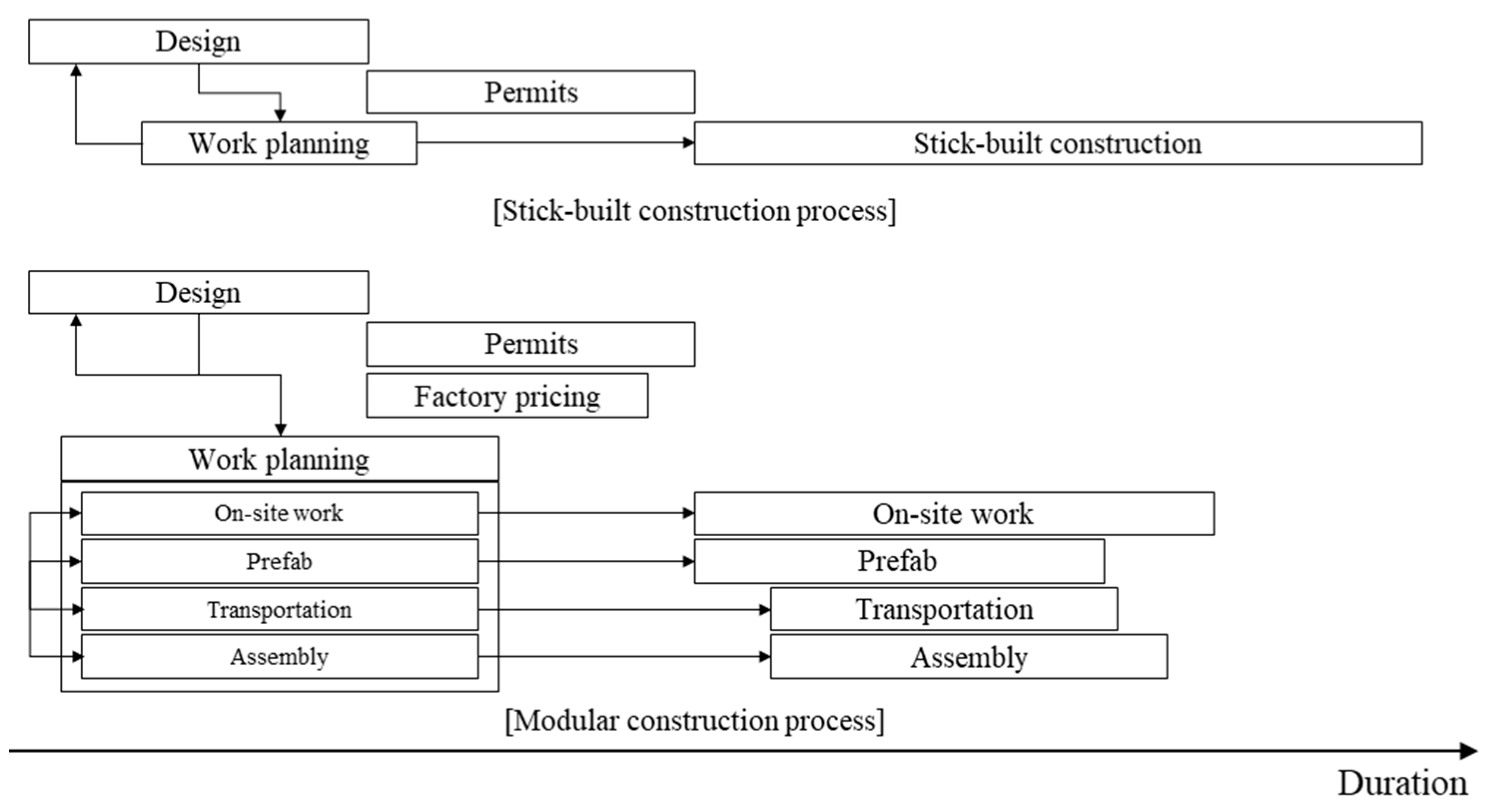
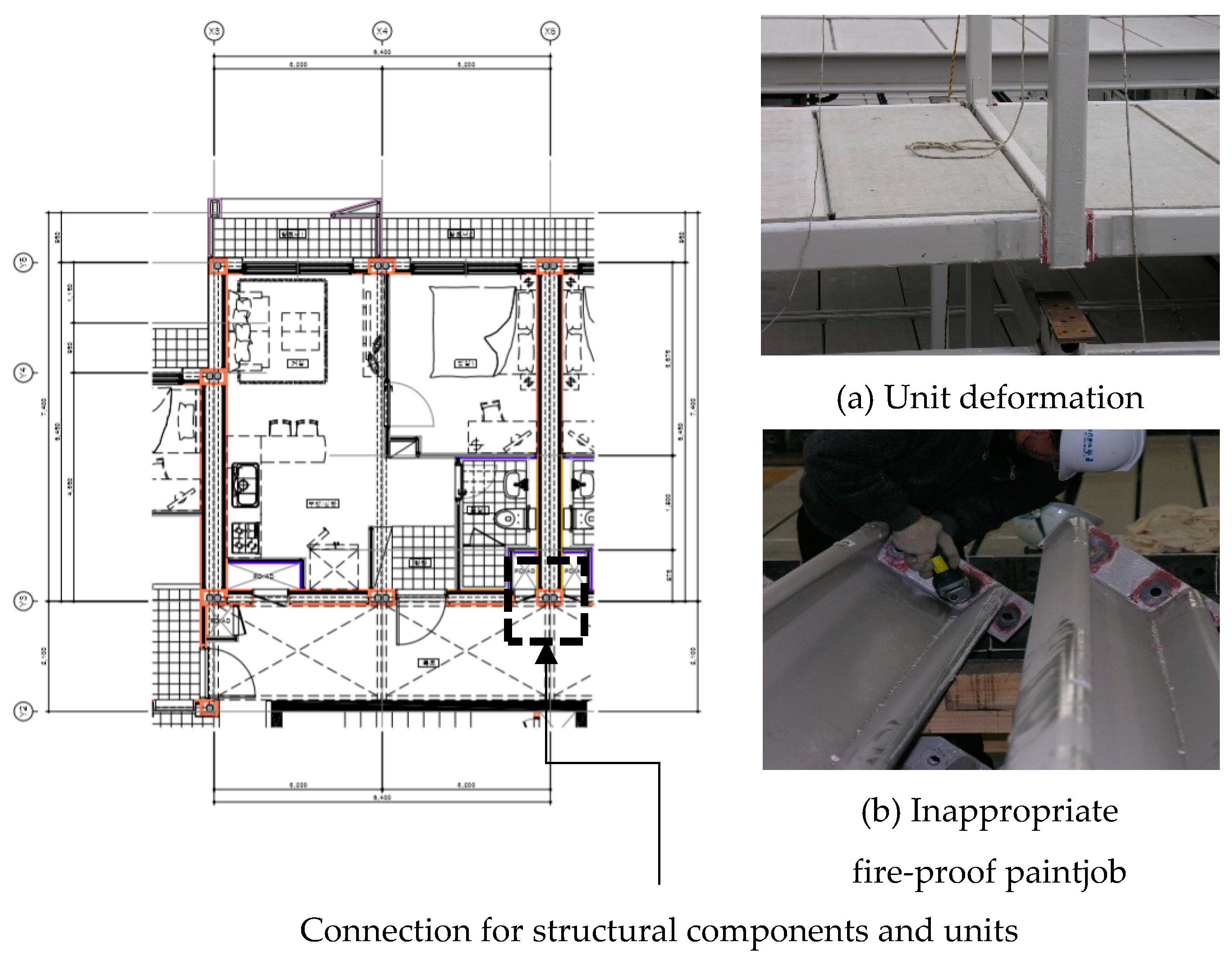
2.1. Rework in Modular Construction Projects

Rework is simply defined as the unnecessary effort of redoing a process or activity that was incorrectly implemented [17]. Rework significantly affects the cost, schedule, and quality of construction projects. The direct costs alone are estimated to be 2–12% of the total construction cost; hence, rework should be managed effectively [15,17,29,30,31]. The causal relationship and effects of rework are usually analyzed to reduce rework in construction [15,16,20,21,31,32,33]. Typically, a significant proportion of rework is caused by errors made during the design process [15,17]. These errors usually appear downstream, and therefore have a negative impact on a project’s performance [15,17,20,21]. The various causes of errors in the design phase include omissions from the project brief; ineffective or lack of coordination; inaccurate, incomplete, or conflicting documents; or an unrealistic design schedule [15]. To reduce errors in the design phase, it is necessary to integrate, and effectively coordinate among, the participants in the early design phase [16,17,29].
In modular construction, it is necessary for the project participants to be integrated in the early design phase, not only to reduce rework, but also to determine design details, such as unit installation and connection method [13]. Therefore, information from the participants, such as unit production and onsite work manager, should be included and applied to the related design steps [18]. However, using conventional stick-built construction design processes for integrating the participants may also lead to rework in itself, although there may be no errors in the design [18,24]. This is because the stick-built design processes do not suggest when/what/how the information from the other participants is applied. Hence, issues with identification of information flow lead to unnecessary reverse information flows and feedback, increasing the chances of omissions and conflicts between the completed design and requirements from participants. For example, if a modular building structure is designed using the stick-built construction process, and the deformation of units during lifting is not considered in the design, damage to internal or external finishes caused by deformation may occur because the self-load increases during lifting. The damaged finish would need to be reworked onsite [24].
In summary, (1) rework can occur without error in the design document that was established using the stick-built construction design process; (2) information regarding both unit production and onsite work should be applied to the related design step. Moreover, there are various details such as installation and connection method for unit assembly that should be determined, for which multilateral information exchange is required, which in turn increases the complexity of information flows in the design processes, as depicted in Figure 1 [2,22]. Figure 1 shows the extra intermediate process such as unit production, transportation compared to stick-built construction and feedbacks between participants in early phase. This means increased project constraints and considerations related to the extra process, which requires multilateral interactive communication [14]. The increased communication results in increased complexity [34,35].
Figure 2 depicts the rework in structural components caused by omissions and conflict in design [15,16]. The errors causing the rework were not detected before conducting the works, and this proves that the information related to unit production and lifting were not applied to the design. Owing to the nature of modular construction work, any changes made onsite are not only difficult but also prohibitive in terms of cost [12,13,36]. In other words, if the design phase is not coordinated properly, modular construction can cost much more than stick-built construction [2,6,12,22,26,27].
In addition to the absence of an integrated process, there is currently limited expertise in modular construction in the marketplace; hence, the approach to design is still largely based on traditional methods [18,37,38]. This may lead to difficulty in identifying errors and omissions in the design, especially with complex information flows [15,17]. Figure 3 depicts the impact of undetected omissions in each design step. To alleviate the issue of lack of expertise, an integrated design process is required.
To support the design phase of modular constructions, several studies have been conducted previously [36,37,38,39,40]. Nahangi et al., proposed an automated approach for monitoring the defection and damage of modular units using laser scanned data [36]. Han et al., developed an optimization model for tower crane operation that can be used in the planning phase [39]. Lei et al., suggested an automated method for checking crane path, and the method could be used to prevent interference during tower crane operation in the planning phase [40]. Olearczyk et al. proposed a methodology for selecting tower crane capacity and location that can be used in the early planning phase [41]. To facilitate the decision making process in the design phase, Sharafi et al., developed a unified matrix approach for the automated design of multi-story modular buildings to effectively compare the building design alternatives in the early design phase considering architectural, structural, and constructional aspects. By using the approach, design alternatives can be suggested considering multidimensional relationship between units and spatial design that are able to achieve minimum cost, maximum regularity, efficient building energy consumption [37]. Then, Sharafi et al., suggested a list of critical decision making criteria that can be used for feasibility studies to select construction methods, such as the modular construction and stick-built construction methods, and developed a decision support system to facilitate the decision making process. By using the process, an appropriate construction system and the level of modularity can be determined [38]. These studies proved the importance of decision making in the early design phase and provided considerations that should be included for efficient modular building design. Smith identified the major issues; suggested guidelines for design, unit production, transportation, and onsite work planning; and analyzed the effect of design and planning change in the early stages [12]. However, these studies did not analyze the information relationship between activities in the design phase or an integrated design process. In summary, the project participants should be integrated to reduce errors in the design phase. However, the errors cannot be reduced only by participation and without the integrated design process. To reduce the errors, this paper proposes an integrated design process to identify and facilitate the information flow between participants.

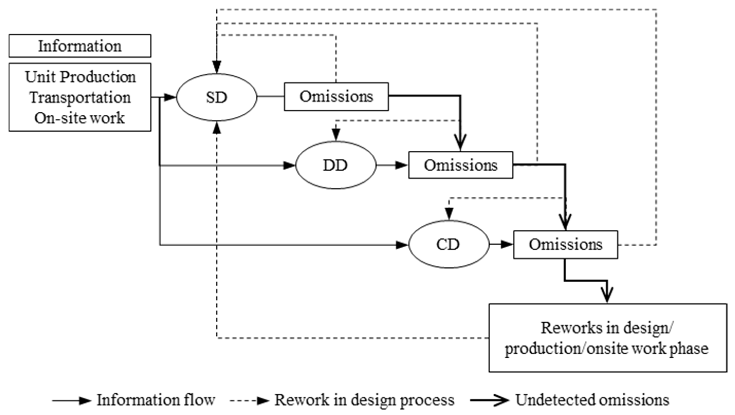
2.2. Information Flow in the Design Process

To use the proposed process in the design phase, it should be established beforehand, and information from participants should be applied to the process. Therefore, what information is required at each design step and which activity generates the information needs to be identified. The information may include considerations for unit production, transportation, onsite work, or the whole project, which should be applied to the design. In addition to this, activities in each design step require information in advance, and information from each participant requires preceding activities. Activities that generate information have different precedence relationships, and feedback occurs between participants. This multilateral information exchange increases the complexity of the information flows, which acts as a source of errors—as identified earlier, omissions and conflicts. It has usually been difficult to handle this complexity because of unawareness and limited expertise in information flow management [18,22,24]. To alleviate the issue, information flows should be first identified, and then feedback in the flow should be managed to facilitate the design process.
To identify the information flow in a process, network analysis and bar chart techniques for planning construction work have been used extensively, but they are not capable of dealing with iterations in the planning process, such as feedback processes between activities [42]. To represent and solve the problem caused by information flow in a process, IDEF0 is used. In the IDEF0 model, an activity can be divided into sub-activities. Moreover, the flow representing input or output data of activities can be identified in the model, which is useful in modeling the system processes based on the information relationship between activities [43]. However, IDEF0 also does not have the capability to manage the feedback process and iterations in the system because the involved activity amount is too large, and the graph in the model will become unclear [43,44,45]. DSM has been used in modular building design [37,46]. Sharafi, Samali et al., used DSM for representing the connection type between modules and 3-dimensional cost optimized building design can be suggested using the unified matrix method in the paper. In the DSM, various interaction types are used for representing connection types between components [37]. DSM has also been used to improve the workflow of the modular unit production process based on the precedence relationship between activities on the production line [46]. It has been used to identify information flows and iterations within a process and to schedule activities with the objective of optimizing the task order. After the identification of information flow, DSM rearranges the order of activities to reduce unnecessary feedbacks and reverse information flows, thereby reducing engineering rework in the planning phase [42,47]. Therefore, DSM can be used to identify and facilitate information flows in the integrated design process for modular construction and to alleviate the complexity of the flow. In DSM, the relationship among activities can be characterized by three fundamental building blocks: parallel (independent), sequential (dependent), and coupled (interdependent), as shown in Figure 4. After the relationship is identified based on the relationship type, process optimization is conducted to reduce feedbacks and iterations in the process. There are various algorithms for process optimization, such as partitioning, tearing, clustering; an algorithm is selected based on the optimization objective. In this paper, a partitioning algorithm, which can help reduce feedback processes based on the information flow by reallocating the activity order, is used [42]. The partitioning algorithm manipulates the rows and columns in DSM to minimize feedbacks in the rearranged DSM. In the partitioning process, the activity that can be conducted without input from other activities is identified and placed at the top of the matrix; this process is iteratively conducted until no such activity remains. After the previous step, the activity delivering no information to other activity is identified and placed at the bottom of matrix and this process also repeated. Completion of these process means the DSM is partitioned [28]. Then, to manage the remaining feedback or reverse information flow, a clustering algorithm is used. The objective of clustering is to find subsets of DSM elements that are called clusters. The clusters should contain most of the interaction between activities internally and the clusters are generated based on the rule that the link or interaction between the clusters should be eliminated or minimized [28]. Using the clustering algorithm, the number of clusters can be minimized and it means a reduced number of feedback loops in the process. In modular projects, the reduced number of clusters means the project participants groups for sharing information can also be reduced and thus, improvement in the efficiency of information flow management.

3. Information Flow Identification

3.1. Activities in Design Phase

To conceptualize an integrated design process, the information flow of the design process was first identified. This identification was based on the precedence relationship of each activity in the design phase. The precedence relationship includes activities that generate information, which is in turn required to conduct activities in the design steps. Based on the identified information flow, a DSM was established. It was then optimized using a partitioning algorithm to suggest an integrated design process [46,47]. The process consists of activities involved in the design process of the conventional stick-built construction. The scope of the process includes schematic design (SD), design development (DD), and construction documentation (CD). The American Institute of Architecture (AIA) has defined the typical building design process [48]. The activities in each design step were adopted from the process of the AIA and limited to those activities related to the determination of architectural, structural, electrical, and mechanical design. In this paper, the adopted activities were subdivided to represent the interaction between architecture and architectural engineers, such as mechanical–structural engineer. For example, article 3.2.5 in the AIA standard form agreement describes SD documents as follows: “Preliminary selections of major building systems and construction materials shall be noted on the drawings or described in writing”. This article describes building systems and materials that should be provided in the SD documentation. However, the same comprehensive description cannot be used for the proposed integrated design process because the activities in the description, such as selecting building system and material, require different information to determine the specifications. Therefore, the description is subdivided, and the subdivided activities related to, inter alia, the building system and materials are listed in Table 1 from ID 5 to 8 [12,13,24,39].
All of the subdivided activities in each design step are listed in Table 1. The subdivided activities are conducted similar to activities in the design process for a conventional stick-built construction. In the SD phase, site layout planning is developed based on the site analysis results in the pre-design phase. Then, materials and a structural system are applied to each building design alternative. The alternatives are prepared to be selected for the DD phase, where the building design is selected among design alternatives and, finally, the selected design is developed. In this phase, materials that will be applied to the design are selected. Each project participant reviews the electrical, mechanical, and structural systems through a feedback process between participants. In the CD phase, details of the building components; mechanical, electrical, and plumbing (MEP); and structural system are documented. The document should be crosschecked by various participants because undetected errors in this phase directly lead to rework in the unit production and onsite work.

3.2. Causes of Rework in Modular Constructions

As mentioned earlier, rework can be classified into two categories: engineering rework and field rework [29,49,50]. The proposed integrated design process intends to reduce engineering rework, which is rework made to rectify errors or omissions in the design phase. In this paper, it is assumed that engineering rework in modular projects occurs when information from participants is omitted in the design phase. To identify such information, many works were reviewed, focusing on modular construction planning [12,13,24,36,39,40,41,51,52,53,54,55,56]. However, rework is also performed to rectify defects after the design phase, such as the unit production, transportation, or onsite work phases. Rework conducted in these phases is called field rework in this paper. Field rework also affects project performance. A significant portion of the causes of field rework are from errors and omissions that are not detected in the design phase [15,17]. An efficient measure to reduce field rework is to develop improved design procedures by incorporating work planning to check causes [49]. In order to include activities that should be integrated into the design process to reduce rework, causes of rework that are not included in the existing literature are identified by analyzing daily reports of modular projects, which document details of work activities and issues. These cases and their causes of rework are collected from daily reports and other sources in the literature, as presented in Table 2. Then, activities to mitigate rework are established. The mitigation plans related to the causes are derived from the literature [12,13,24,36,39,40,41,51,52,53,54,55,56]. The mitigation plans are described in Table 3. Each mitigation plan is an activity in the work plan for off/on-site work that should be integrated into the design process. Activities in the mitigation plan consist of activities for reviewing or checking the causes, and errors in design can be reduced by conducting the activities in the design phase. For example, in Figure 2, rework was caused because a fireproof paint was applied to a unit assembly connection. Fireproof paint should not be applied to such connections as the structural performance of the painted connection may decrease. Therefore, the paint had to be removed from the connection and the units had to be reassembled. This implies that the interference between fireproof painting and connection was not marked in the shop drawing for unit manufacturing. To prevent rework, an activity whereby errors and omissions in the design are checked is included, to be conducted while preparing shop drawings in the manufacturing planning phase.

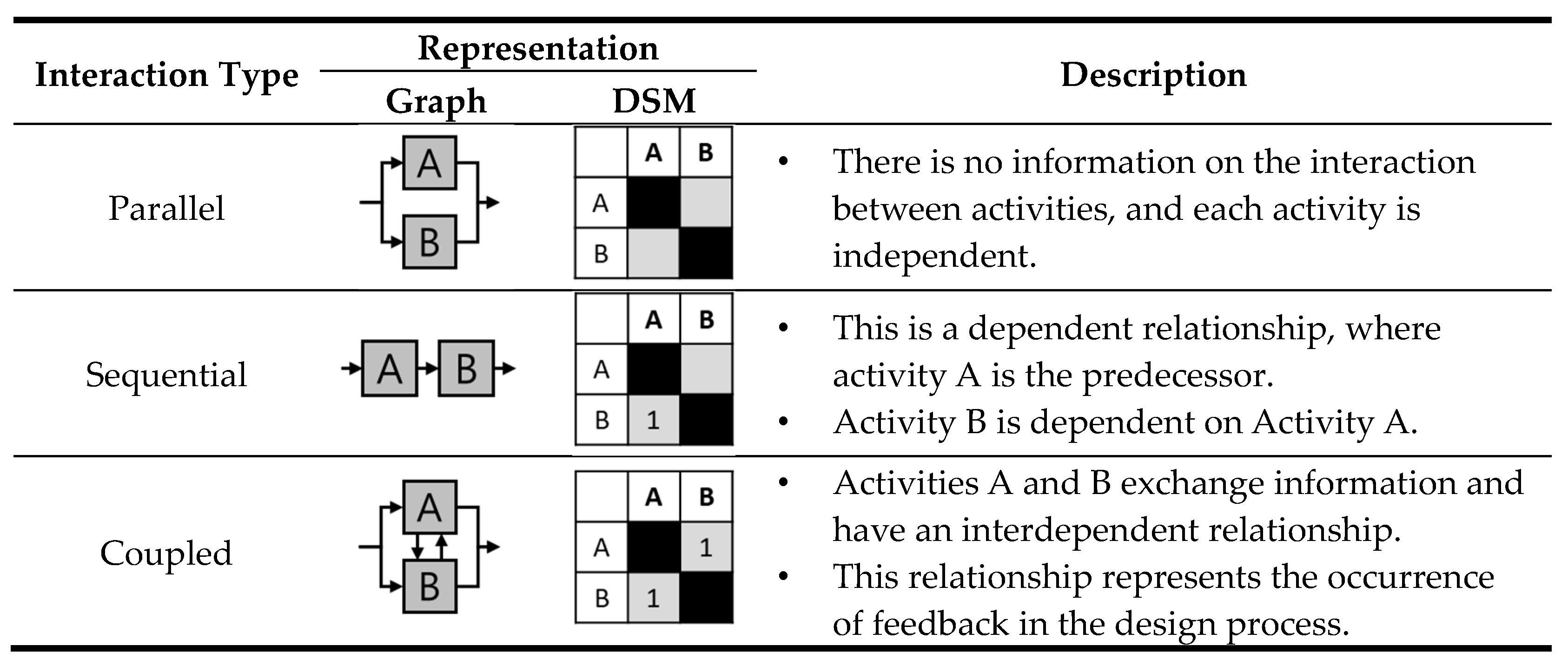
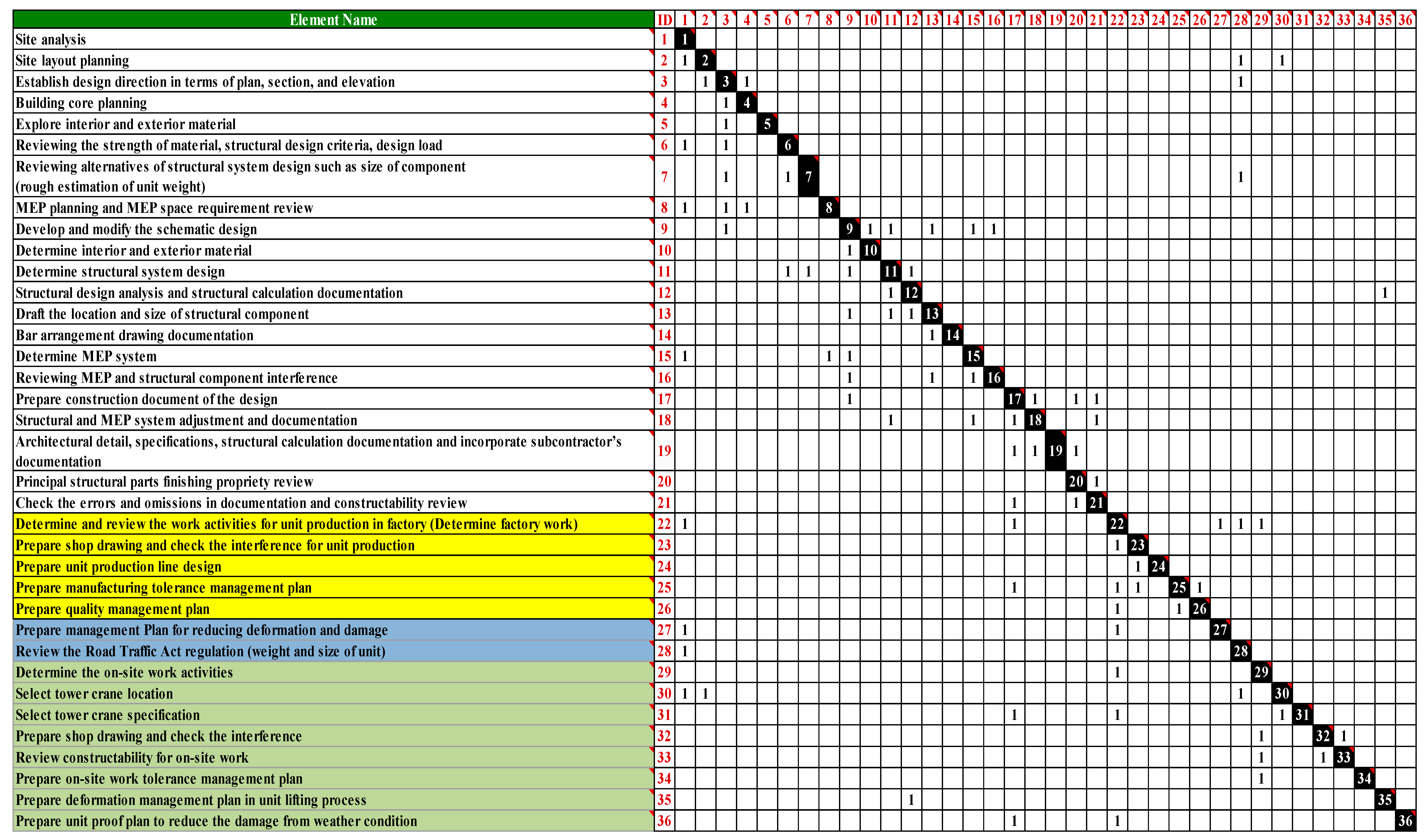
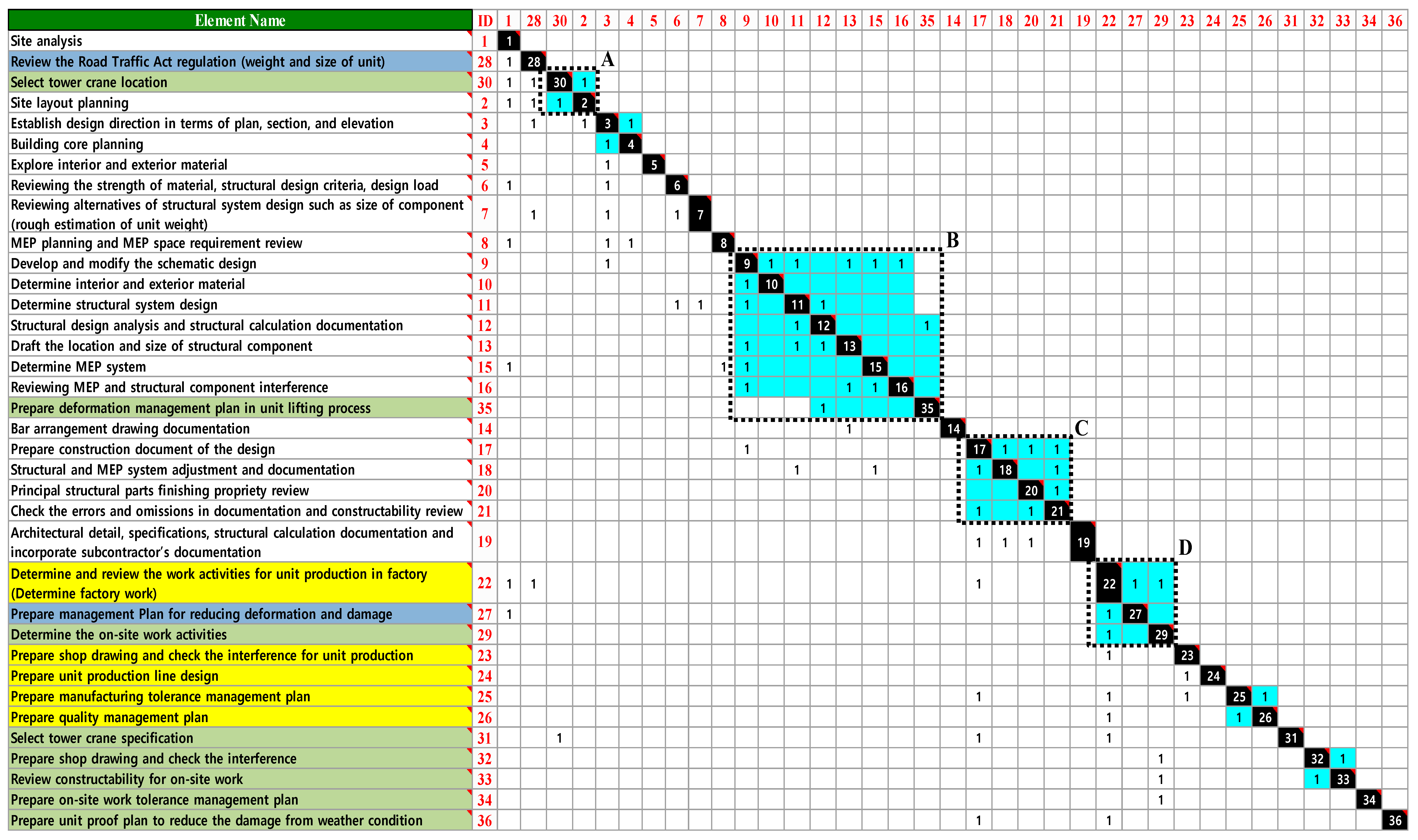
3.3. Identification of Information Flow for DSM

To develop the proposed integrated design process, including the rework mitigation plan, the information flows between activities should be identified. Through this identification, the activities in the process are rearranged to facilitate information flows using the partitioning algorithm. Through the rearrangement, activities in the mitigation plan are allocated in the design process, and the type and time of information from project participants to be shared are provided. Therefore, the integrated process shows the procedure of the design process including the activities in the mitigation plan. In Table 4, the information flow between activities in the designing and planning phases has been identified [12,13,24,36,39,40,41,51,52,53,54,55,56]. Each activity in Table 4 has predecessors. The predecessor column lists the IDs of the activities that must be conducted before each activity. In other words, the activity can only start with the information obtained by completing the predecessor activities. For example, site layout planning should be preceded by activities, such as site analysis, reviewing the Road Traffic Act regulations, and tower crane location selection. However, when selecting the tower crane location, the site layout planning is considered to be a predecessor, which implies that there is a feedback process between the site layout planning and tower crane location selection. Therefore, when conducting activities, activity information, such as building and crane location, should be exchanged and shared. Moreover, the Road Traffic Act regulation review follows the activity of site layout planning while also providing the site layout planning activity with information. The reverse information flow here indicates that there is a possibility of engineering rework in the design phase. Feedback and reverse information flows can be reduced by rearranging the activity order during the optimization of the design process. The order is rearranged based on information flows.
For the rearrangement, a DSM of the modular construction design process was developed based on the information flow relationship in Table 4. Figure 5 illustrates the DSM. The marks above the diagonal represent the reverse information flows. The optimization objective of the DSM is to move as many marks as possible to below the diagonal [47]. Figure 6 depicts the rearranged activities and information flow in the DSM after applying the partitioning algorithm. Then, activities with strong interdependencies were grouped, and each group has feedback and reverse information flow between activities. The blue boxes in Figure 6 indicate the groups, and to constitute the blue box, a clustering algorithm was used. Although the number of feedback processes were reduced by the optimization, some still remain. Activity groups A, B, C, and D require information flow management, because the feedback processes are concentrated within the groups. As a quantitative result, the total number of reverse information flows in the process was reduced from 23 to 18 after rearrangement of the activity order. For example, the Road Traffic Act regulations review in the transportation planning phase was reallocated to the SD phase. The reverse information flow of reviewing the regulation was reduced from 4 to 0. This reduced reverse flow implies that the regulation review affects other activities in the process. By allocating the regulation review to the early design phase, engineering rework in the design and planning phases can be reduced. Given that the results of the SD phase affect the following activities, reallocation in the early phase implies that the potential rework in the following phase can also be reduced.

4. Integrated Design Process for Modular Construction

4.1. Schematic Design Phase

Through DSM optimization, activities in the design phase and rework mitigation plan were rearranged and an integrated design process was suggested. In the process, activities are conducted sequentially from above. The marks on the matrix refer to the relationship described in Figure 4 and the marks on the diagonal line indicate feedback or reverse information flow. Using this process, it is expected that reworks in modular projects will be reduced. In this section, each design step in the design phase is explained, focusing on the rearranged activities and groups of activities. In the schematic design step, the Road Traffic Act regulations review in transportation planning and tower crane location selection in onsite work planning were included. When developing building design alternatives, it is necessary to review the Road Traffic Act regulations [12,55]. If the design does not meet the regulations, the building design is reworked because modular units must be transported to the site.
In this step, activity group A indicates the feedback process between the site layout planning and tower crane location selection. In the planning phase of the onsite work, the selection and positioning of tower cranes on the construction site are essential, because heavy units must be lifted [39,51,52]. In the tower crane operational plan, capacity is estimated based on a combination of the maximum distance that the tower crane must reach and the weight of the material. By reducing the maximum distance, the tower crane’s operational cost can be reduced. For example, in the SD phase, after estimating the approximate weight of the unit, tower crane location alternatives are suggested considering the alternative site layout planning. Then, the tower crane capacity can be estimated on the basis of the combination of alternatives. If a tower crane with the required capacity cannot be obtained from a crane rental company or if the operational cost is uneconomical, the weight of the unit, the location of the crane, or the site layout plan are modified to meet the project objectives. After the design process—along with the regulation review and tower crane operation—is completed, a building design is selected from among the design alternatives by considering the feasibility and project objectives.

4.2. Design Development Phase

In this phase, the selected design from the schematic design phase is developed and the building systems—such as architectural, structural, and MEP systems—are determined. Activity group B shows the feedback process between activities to determine the building systems. To facilitate information interchange between project participants, information flow management is required. In this phase, when developing the MEP and structural design, interference between these activities often occurs [55,56]. Therefore, to reduce rework caused by interference, an accurate design review between activities is required, which implies that there will be feedback in this design process.
In this phase, onsite work planning is included to prevent the deformation of units [12,24]. When lifting a unit onsite, deformation caused by self-load of the unit can occur. This can affect the quality of unit and cause difficulties during the onsite unit assembly phase. To prevent this deformation, a balance beam can be used; however, deformation may still occur for heavy units. There is also an approved deformation range in the assembly phase. However, when the deformation exceeds the approved range, rework to revise the deformation should be conducted. The higher the quality and precision standards of the modular units, the higher the probability of running into common problems when using less precise components onsite or when the precision of the unit decreases [18]. Therefore, when selecting the structural system and conducting structural analysis of units, it is necessary to plan for preventing deformation induced by self-load.

4.3. Construction Documentation Phase

In this phase, the results of the previous phase are developed, and details are determined. Then, construction documents, such as drawings for details and specifications are prepared for manufacturing and onsite work. In this phase, the participants in the design planning phase crosscheck the design documents to rectify errors and omissions. The design document is used to prepare shop drawings for unit production and onsite work. The quality of shop drawings is directly related to project quality. Hence, interference between components or activities should be checked and rectified. Activity group C shows the feedback process in this phase. Here, constructability, information interchange, and rectification should be facilitated between participants [12,13,24].

4.4. Manufacturing, Transportation, and Onsite Work Planning Phase

In this phase, manufacturing, transportation, and onsite work plans, which are not included in the previous design phases, are finalized based on the results of the CD phase. To improve the efficiency of modular construction, the largest number of activities possible must be conducted in the manufacturing process. After the manufacturing process, units are transported to the construction site. It is necessary to establish the work plans according to the site environment and road conditions. Therefore, the work activities conducted in the manufacturing process are selected considering the unit deformation in transportation, damage to units, and site environment. Then, the remaining activities to complete the project are conducted onsite. Given that the work proportions are determined depending on the project characteristics, the proportions are flexible. This work activity distribution is shown by the activity group D in Figure 6. In this group, manufacturing, transportation, and onsite work plans are cross-checked and rectified by the participants. Therefore, it involves feedback processes between activities, and therefore, cooperation is required between participants. Moreover, in addition to work planning related to rework, other work planning for activities is also included in this phase.
The proposed design process can contribute to reducing rework in modular construction projects by integrating the rework mitigation plans and work planning. To employ this planning process, modular construction must be considered in the early project phase by the project client or in the early design stage. Then, to facilitate the process and include project participants in the early design phase, project delivery methods, such as integrated project delivery (IPD), should also be considered [12]. However, there are many hindrances to choosing modular construction, such as early design freeze, limited experience, short overall project timescale, and lack of availability of advice in the early phase [22]. Moreover, follow-on projects cannot use the same processes as previous projects, which is a constraint caused by a lack of experience and knowledge [22]. To overcome this, a standardized modular construction process is required. The proposed design process can be used to overcome the constraints and reduce rework in modular construction.

5. Discussion

To facilitate information flow in the design process, an integrated design process was suggested using DSM. To validate the process and effect on reducing errors in the design phase, an expert interview was conducted. The expert group consisted of researchers and architects; experts with over 5 years of experience in modular construction. In the interview, the experts agreed that an integrated design process is required to reduce errors in the design phase, and that the suggested process could reduce the errors. Since each participant in the process is a non-professional in all of the other fields (for example, a manager in a transportation company without knowledge of design processes), they do not know to whom or at what stage they should provide relevant information. Therefore, error can be reduced by informing them of what information should be provided to other participants and when. However, they also mentioned that further investigation into the information relationship between activities is required to find the unidentified relationship in this paper. For example, when planning tower crane operation, the crane may be located near the building core to attach the crane to the core. This means that the increased load caused by tower crane operation should be included in the structural design of the building core, because of the heavy weight of the unit and crane. Therefore, this unidentified relationship should be further investigated and included in the suggested design process. Moreover, the above-mentioned experts who are to use the process should consider project delivery methods at the beginning of the project, because some methods such as design-bid-building do not allow early integration of participants. The expert interview results show the effect and necessity of the process. However, there are limitations. In real projects, various decision-making criteria, such as level of modularity and integration strategies, are applied in the design phase that affect the design process, but these have not been considered in this paper, as they are outside the scope of study. In this paper, the design process of the AIA was applied to the suggested process, but when applied to other countries, legal considerations need to be reviewed. Moreover, to represent the information flow more clearly, various types of relationship can be used, representing the type of information or subject of information exchange, but the DSM in this paper used only 3 types of relationship. Thus, it can only represent information flow as a binary system. Finally, to ensure the robustness of this research, further validation of the process through application to a real project is required.

6. Conclusions

An integrated design process was developed using DSM and optimized using a partitioning algorithm. Through process optimization, feedback and reverse information flows were reduced, and thus, the complexity of the design process was alleviated. It is expected that rework in modular projects can be reduced by using the proposed process. Additionally, by using the information flow identification method proposed in this paper, other considerations for modular projects can also be included in the process. However, the process has limitations in that (1) application of the process to modular projects is required for validation; (2) the cases and causes of rework used are limited to only a few cases in the daily report and literature; and (3) the process is not able to suggest information about participants, i.e., who should be included for each activity in the planning process; and (4) although many criteria affect the decision-making process in the design phase, such as quality, safety, cost and constructability, the suggested design process in this paper focused on the information relationship between activities, and thus, the effect of the suggested process on the criteria were not considered. To overcome these limitations, other criteria affecting the design process should be included in the integrated design process. Accordingly, a case study including more cases of rework and validation will be conducted in future research.

Author Contributions

Conceptualization, H.H. and J.L.; methodology, H.H.; formal analysis, H.K. and H.-S.L.; investigation, H.H.; resources, H.H.; writing—original draft preparation, H.H. and J.L.; writing—review and editing, M.P., H.K, and H.-S.L.; project administration, H.-S.L.; funding acquisition, H.-S.L. All authors have contributed substantially to the work reported. All authors have read and agreed to the published version of the manuscript.

Funding

This work was supported by the Housing Environment Research Program funded by Ministry of Land, Infrastructure and Transport of Government of Korea (Grant number 20RERP-B082884-07).

Acknowledgments

The authors would also like thanks to Ministry of Land, Infrastructure and Transport of Government of Korea, Housing Environment Research Program, Korea Agency for Infrastructure Technology Advancement for supporting this research.

Conflicts of Interest

The authors declare no conflict of interest.

References

  1. Chen, Y.; Okudan, G.E.; Riley, D.R. Sustainable performance criteria for construction method selection in concrete buildings. Automa. Constr. 2010, 19, 235–244. [Google Scholar] [CrossRef]
  2. Lu, N. The current use of offsite construction techniques in the United States construction industry. In Proceedings of the Construction Research Congress 2009, Seattle, WA, USA, 5–7 April 2009; p. 96. [Google Scholar]
  3. Boafo, F.E.; Kim, J.-H.; Kim, J.-T. Performance of modular prefabricated architecture: Case study-based review and future pathways. Sustainability 2016, 8, 558. [Google Scholar] [CrossRef] [Green Version]
  4. Eastman, C.M.; Sacks, R. Relative productivity in the AEC industries in the United States for on-site and off-site activities. J. Constr. Eng. Manag. 2008, 134, 517–526. [Google Scholar] [CrossRef]
  5. Mullens, M.A. Factory Design for Modular Homebuilding: Equipping the Modular Factory for Success; Constructability Press: Winter Park, FL, USA, 2011. [Google Scholar]
  6. Shaked, O.; Warszawski, A. CONSCHED: Expert system for scheduling of modular construction projects. J. Constr. Eng. Manag. 1992, 118, 488–506. [Google Scholar] [CrossRef]
  7. Lawson, R.M.; Ogden, R.G.; Bergin, R. Application of modular construction in high-rise buildings. J. Archit. Eng. 2011, 18, 148–154. [Google Scholar] [CrossRef]
  8. Shen, K.; Cheng, C.; Li, X.; Zhang, Z. Environmental Cost-Benefit Analysis of Prefabricated Public Housing in Beijing. Sustainability 2019, 11, 207. [Google Scholar] [CrossRef] [Green Version]
  9. Whole Building Design Guide Sustainable (WBDG). Available online: http://www.wbdg.org/design-objectives/sustainable (accessed on 11 February 2019).
  10. Jiang, Y.; Zhao, D.; Wang, D.; Xing, Y. Sustainable Performance of Buildings through Modular Prefabrication in the Construction Phase: A Comparative Study. Sustainability 2019, 11, 5458. [Google Scholar] [CrossRef] [Green Version]
  11. Lee, J.-H.; Kim, J.-S.; Lee, H.-J.; Lee, Y.-M.; Kim, H.-G. Small-Scale Public Rental Housing Development Using Modular Construction—Lessons learned from Case Studies in Seoul, Korea. Sustainability 2019, 11, 1120. [Google Scholar] [CrossRef] [Green Version]
  12. Smith, R.E. Prefab Architecture: A Guide to Modular Design and Construction; John Wiley & Sons: Hoboken, NJ, USA, 2011. [Google Scholar]
  13. Lawson, M.; Ogden, R.; Goodier, C. Design in Modular Construction; CRC Press: Boca Raton, FL, USA, 2014. [Google Scholar]
  14. Alvanchi, A.; Azimi, R.; Lee, S.; AbouRizk, S.M.; Zubick, P. Off-site construction planning using discrete event simulation. J. Archit. Eng. 2011, 18, 114–122. [Google Scholar] [CrossRef]
  15. Love, P.E.; Mandal, P.; Li, H. Determining the causal structure of rework influences in construction. Constr. Manag. Econ. 1999, 17, 505–517. [Google Scholar] [CrossRef]
  16. Love, P.E.; Li, H.; Mandal, P. Rework: A symptom of a dysfunctional supply-chain. Eur. J. Purch. Supply Manag. 1999, 5, 1–11. [Google Scholar] [CrossRef]
  17. Love, P.E.; Li, H. Quantifying the causes and costs of rework in construction. Constr. Manag. Econ. 2000, 18, 479–490. [Google Scholar] [CrossRef]
  18. Blismas, N.; Wakefield, R. Drivers, constraints and the future of offsite manufacture in Australia. Constr. Innov. 2009, 9, 72–83. [Google Scholar] [CrossRef] [Green Version]
  19. Johnsson, H.; Meiling, J.H. Defects in offsite construction: Timber module prefabrication. Constr. Manag. Econ. 2009, 27, 667–681. [Google Scholar] [CrossRef]
  20. Love, P.E.; Holt, G.D.; Shen, L.Y.; Li, H.; Irani, Z. Using systems dynamics to better understand change and rework in construction project management systems. Int. J. Proj. Manag. 2002, 20, 425–436. [Google Scholar] [CrossRef]
  21. Love, P.E.; Edwards, D.J. Determinants of rework in building construction projects. Eng. Constr. Archit. Manag. 2004, 11, 259–274. [Google Scholar] [CrossRef]
  22. Blismas, N.G.; Pendlebury, M.; Gibb, A.; Pasquire, C. Constraints to the use of off-site production on construction projects. Archit. Eng. Des. Manag. 2005, 1, 153–162. [Google Scholar] [CrossRef] [Green Version]
  23. Jiang, L.; Li, Z.; Li, L.; Gao, Y. Constraints on the promotion of prefabricated construction in China. Sustainability 2018, 10, 2516. [Google Scholar] [CrossRef] [Green Version]
  24. Park, H.K.; Ock, J.-H. Unit modular in-fill construction method for high-rise buildings. KSCE J. Civ. Eng. 2016, 20, 1201–1210. [Google Scholar] [CrossRef]
  25. Pasquire, C.L.; Gibb, A.G. Considerations for assessing the benefits of standardisation and pre-assembly in construction. J. Financ. Manag. Prop. Constr. 2002, 7, 151–161. [Google Scholar]
  26. Al-Bazi, A.; Dawood, N. Developing crew allocation system for the precast industry using genetic algorithms. Comput. Aided Civ. Infrastruct. Eng. 2010, 25, 581–595. [Google Scholar] [CrossRef] [Green Version]
  27. Arif, M.; Espinal, D.; Broadway, R.S. Estimating, Planning and Controlling Labor in the Industrialized Housing Factory. In IIE Annual Conference. Proceedings; Institute of Industrial Engineers-Publisher: Orlando, FL, USA, 2002; p. 1. [Google Scholar]
  28. Yassine, A.; Braha, D. Complex concurrent engineering and the design structure matrix method. Concurr. Eng. 2003, 1, 165–176. [Google Scholar] [CrossRef]
  29. Hwang, B.-G.; Thomas, S.R.; Haas, C.T.; Caldas, C.H. Measuring the impact of rework on construction cost performance. J. Constr. Eng. Manag. 2009, 135, 187–198. [Google Scholar] [CrossRef]
  30. Josephson, P.-E.; Hammarlund, Y. The causes and costs of defects in construction: A study of seven building projects. Autom. Constr. 1999, 8, 681–687. [Google Scholar] [CrossRef]
  31. Smith, G.; Jirik, T. Making Zero Rework a Reality: A Comparison of Zero Accident Methodology to Zero Rework and Quality Management; Research Report; Construction Industry Institute: Austin, TX, USA, 2006; pp. 203–211. [Google Scholar]
  32. Burati, J.L., Jr.; Farrington, J.J.; Ledbetter, W.B. Causes of quality deviations in design and construction. J. Constr. Eng. Manag. 1992, 118, 34–49. [Google Scholar] [CrossRef]
  33. Rahmandad, H.; Hu, K. Modeling the rework cycle: Capturing multiple defects per task. Syst. Dyn. Rev. 2010, 26, 291–315. [Google Scholar] [CrossRef]
  34. Bruns, T.; Stalker, G. The Management of Innovation; Tavistock: London, UK, 1961; pp. 120–122. [Google Scholar]
  35. Gidado, K. Project complexity: The focal point of construction production planning. Constr. Manag. Econ. 1996, 14, 213–225. [Google Scholar] [CrossRef]
  36. Nahangi, M.; Safa, M.; Shahi, A.; Haas, C.T. Automated registration of 3D point clouds with 3D CAD models for remote assessment of staged fabrication. In Proceedings of the Construction Research Congress 2014: Construction in a Global Network, Atlanta, GA, USA, 19–21 May 2014; pp. 1004–1013. [Google Scholar]
  37. Sharafi, P.; Samali, B.; Ronagh, H.; Ghodrat, M. Automated spatial design of multi-story modular buildings using a unified matrix method. Autom. Constr. 2017, 82, 31–42. [Google Scholar] [CrossRef]
  38. Sharafi, P.; Rashidi, M.; Samali, B.; Ronagh, H. Identification of factors and decision analysis of the level of modularization in building construction. J. Archit. Eng. 2018, 24, 04018010. [Google Scholar] [CrossRef]
  39. Han, S.H.; Hasan, S.; Bouferguène, A.; Al-Hussein, M.; Kosa, J. Utilization of 3D visualization of mobile crane operations for modular construction on-site assembly. J. Manag. Eng. 2014, 31, 04014080. [Google Scholar] [CrossRef]
  40. Lei, Z.; Taghaddos, H.; Olearczyk, J.; Al-Hussein, M.; Hermann, U. Automated method for checking crane paths for heavy lifts in industrial projects. J. Constr. Eng. Manag. 2013, 139, 04013011. [Google Scholar] [CrossRef]
  41. Olearczyk, J.; Al-Hussein, M.; Bouferguène, A. Evolution of the crane selection and on-site utilization process for modular construction multilifts. Autom. Constr. 2014, 43, 59–72. [Google Scholar] [CrossRef]
  42. Austin, S.; Baldwin, A.; Li, B.; Waskett, P. Analytical design planning technique ADePT): A dependency structure matrix tool to schedule the building design process. Constr. Manag. Econ. 2000, 18, 173–182. [Google Scholar] [CrossRef] [Green Version]
  43. Giaglis, G.M. A taxonomy of business process modeling and information systems modeling techniques. Int. J. Flex. Manuf. Syst. 2001, 13, 209–228. [Google Scholar] [CrossRef]
  44. Mayer, R.J.; Benjamin, P.C.; Caraway, B.E.; Painter, M.K. A framework and a suite of methods for business process reengineering. Bus. Process Reeng. Manag. Perspect. 1995, 3, 245–290. [Google Scholar]
  45. Wei, H.-Q. Concurrent design process analysis and optimization for aluminum profile extrusion product development. Int. J. Adv. Manuf. Technol. 2007, 33, 652–661. [Google Scholar] [CrossRef]
  46. Lee, J.; Park, M.; Lee, H.-S.; Kim, T.; Kim, S.; Hyun, H. Workflow dependency approach for modular building construction manufacturing process using Dependency Structure Matrix (DSM). KSCE J. Civ. Eng. 2017, 21, 1525–1535. [Google Scholar] [CrossRef]
  47. Oloufa, A.A.; Hosni, Y.A.; Fayez, M.; Axelsson, P. Using DSM for modeling information flow in construction design projects. Civ. Eng. Environ. Syst. 2004, 21, 105–125. [Google Scholar] [CrossRef]
  48. AIA. The American Institute of Architects Document B101-Standard Form of Agreement between Owner and Architect; AIA: Washington, DC, USA, 2017. [Google Scholar]
  49. Fayek, A.R.; Dissanayake, M.; Campero, O. Developing a standard methodology for measuring and classifying construction field rework. Can. J. Civ. Eng. 2004, 31, 1077–1089. [Google Scholar] [CrossRef]
  50. O’connor, J.T.; Tucker, R.L. Industrial project constructability improvement. J. Constr. Eng. Manag. 1986, 112, 69–82. [Google Scholar] [CrossRef]
  51. Al-Hussein, M.; Alkass, S.; Moselhi, O. An algorithm for mobile crane selection and location on construction sites. Constr. Innov. 2001, 1, 91–105. [Google Scholar] [CrossRef]
  52. Han, S.; Al-Hussein, M.; Hasan, S.; Gökçe, K.U.; Bouferguene, A. Simulation of mobile crane operations in 3D space. In Proceedings of the 2012 Winter Simulation Conference (WSC), Berlin, Germany, 9–12 December 2012; pp. 1–12. [Google Scholar]
  53. Han, S.; Bouferguene, A.; Al-Hussein, M.; Hermann, U. 3D-Based Crane Evaluation System for Mobile Crane Operation Selection on Modular-Based Heavy Construction Sites. J. Constr. Eng. Manag. 2017, 143, 04017060. [Google Scholar] [CrossRef]
  54. Kalasapudi, V.S.; Tang, P.; Zhang, C.; Diosdado, J.; Ganapathy, R. Adaptive 3D imaging and tolerance analysis of prefabricated components for accelerated construction. Procedia Eng. 2015, 118, 1060–1067. [Google Scholar] [CrossRef] [Green Version]
  55. Hwang, B.-G.; Shan, M.; Looi, K.-Y. Key constraints and mitigation strategies for prefabricated prefinished volumetric construction. J. Clean. Prod. 2018, 183, 183–193. [Google Scholar] [CrossRef]
  56. Shahtaheri, Y.; Rausch, C.; West, J.; Haas, C.; Nahangi, M. Managing risk in modular construction using dimensional and geometric tolerance strategies. Autom. Constr. 2017, 83, 303–315. [Google Scholar] [CrossRef]
Figure 1. Increased complexity caused by interposed processes.
Sustainability 12 00530 g001
Figure 2. Examples of errors caused by omission in design.
Sustainability 12 00530 g002
Figure 3. Impact of undetected omissions in each design step.
Sustainability 12 00530 g003
Figure 4. Information relationships in a DSM.
Sustainability 12 00530 g004
Figure 5. Information flow identification using DSM.
Sustainability 12 00530 g005
Figure 6. Rearranged activities after optimization.
Sustainability 12 00530 g006
Table 1. Activities in the design phase.
Design PhaseIDActivities
SD1Site analysis
2Site layout planning
3Establish design direction in terms of plan, section, and elevation
4Building core planning
5Explore interior and exterior material
6Review the strengths of materials, structural design criteria, and design load
7Review alternatives of structural system design, such as size of components (rough estimation of unit weight)
8MEP planning and MEP space requirement review
DD9Develop and modify the schematic design
10Determine interior and exterior materials
11Determine structural system design
12Structural design analysis and structural calculation documentation
13Draft the locations and sizes of structural components
14Bar arrangement drawing documentation
15Determine MEP system
16Review MEP and structural component interference
CD17Prepare construction document of the design
18Structural and MEP system adjustment and documentation
19Architectural detail, specifications, structural calculation documentation and incorporate subcontractor’s documentation
20Principal structural parts finishing propriety review
21Check errors and omissions in documentation and constructability review
Table 2. Cases and causes of rework in modular construction projects.
PhaseCauseRelated Research
ManufacturingInterference between MEP and structural components[19,24,54]
Fireproof paint application to connection[24], daily report
Rework caused by error of activity order on manufacturing line[19,24], daily report
Excess manufacturing tolerance[36]
Quality deterioration in manufacturing process[24,36]
TransportationDamage and deformation in transportation[19,24,55]
Revision of design caused by omission of reviewing Road Traffic Act in the design process[12,13,24]
Onsite workInterference between MEP and structural components, such as concrete foundations[19,24,54], daily report
Damage to unit caused by onsite work interference[24,39,40,41,51,52]
Shortage of passage space for workers in PIT[24], daily report
Occurrence of component tolerance errors[24,56], daily report
Occurrence of tolerance error in MEP[24,54], daily report
Unit deformation caused by unit lifting[12,24]
Damage caused by weather conditions on un-proofed components[24], daily report
Table 3. Mitigation plan for reducing rework.
PhaseIDActivities in Rework Mitigation Plan
Manufacturing22(Production plan) Determine and review the work activities for unit production in the factory (determine factory work)
23(Production plan) Prepare shop drawings and check interference of unit production
24(Production plan) Prepare unit production line design
25(Quality management plan) Prepare manufacturing tolerance management plan
26(Quality management plan) Prepare quality management plan
Transportation27(Transportation plan) Prepare management plan for reducing deformation and damage
28(Transportation plan) Review the Road Traffic Act regulations (check the weight and size of unit)
Onsite Work29(Onsite work plan) Determine onsite work activities
30(Onsite work plan) Select tower crane location
31(Onsite work plan) Select tower crane specification
32(Onsite work plan) Prepare shop drawings and check for interference
33(Onsite work plan) Review constructability for onsite work
34(Quality management plan) Prepare onsite work tolerance management plan
35(Quality management plan) Prepare deformation management plan in unit lifting process
36(Quality management plan) Prepare unit proofing plan to reduce damage from weather conditions
Table 4. Activity relationship based on information flows.
PhaseIDActivitiesPredecessor
Schematic design1Site analysis
2Site layout planning1, 28, 30
3Establish design direction in terms of plan, section, and elevation2, 4, 28
4Building core planning3
5Explore interior and exterior material3
6Reviewing the strength of material, structural design criteria, and design load1, 3
7Reviewing alternatives of structural system designs, such as sizes of component (rough estimation of unit weight) 3, 6, 28
8MEP planning and MEP space requirement review1, 3, 4
Design development9Develop and modify the schematic design3, 10, 11, 13, 15, 16
10Determine interior and exterior materials9
11Determine structural system design6, 7, 9, 12
12Structural design analysis and structural calculation documentation11, 35
13Draft the locations and sizes of structural components9, 11, 12
14Bar arrangement drawing documentation13
15Determine MEP system1, 8, 9
16Reviewing MEP and structural component interference 9, 13, 15
Construction documentation17Prepare construction document of the design 9, 18, 20, 21
18Structural and MEP system adjustment and documentation11, 15, 17, 21
19Architectural details, specifications, and structural calculation documentation and incorporate subcontractor documentation17, 18, 20
20Principal structural parts finishing and propriety review21
21Check the errors and omissions in documentation and constructability review 17, 20
Manufacturing22Determine and review the work activities for unit production in factory (determine factory work)1, 17, 27, 28, 29
23Prepare shop drawings and check interference in unit production22
24Prepare unit production line design23
25Prepare manufacturing tolerance management plan 17, 22, 23, 26
26Prepare quality management plan22, 25
Transportation27Prepare management plan for reducing deformation and damage 1, 22
28Review the Road Traffic Act regulations (weight and size of unit)1
Onsite Work29Determine onsite work activities22
30Select tower crane location1, 2, 28
31Select tower crane specification17, 22, 30
32Prepare shop drawings and check for interference 29, 33
33Review constructability for onsite work29, 32
34Prepare onsite work tolerance management plan29
35Prepare deformation management plan in unit lifting process12
36Prepare unit proofing plan to reduce damage from weather conditions 17, 22

