Design for Additive Manufacturing: A Systematic Review


Abstract
:
1. Introduction
2. The Classification of Design for Additive Manufacturing (DfAM)
2.1. Cellular Structures
2.2. Part Consolidation and Assembly
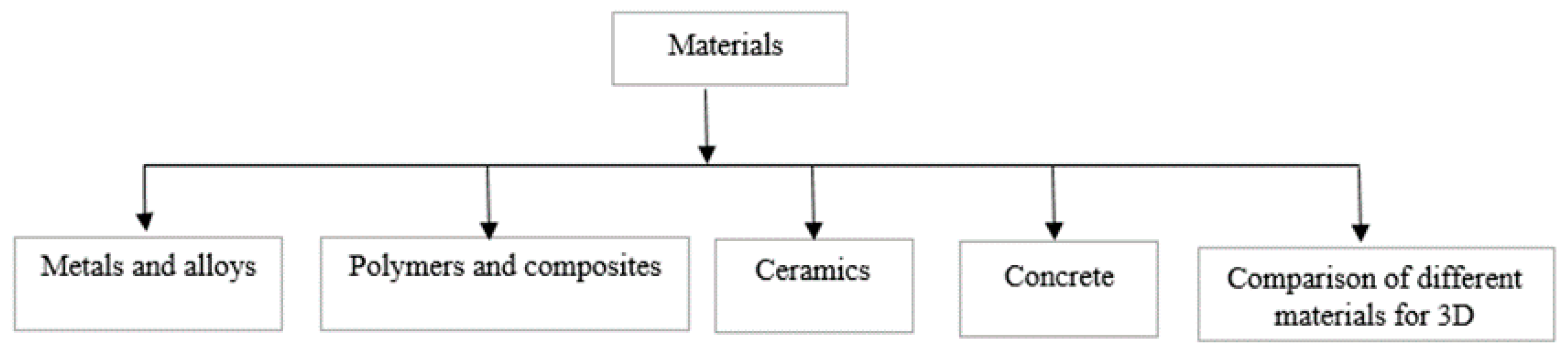
2.3. Materials
2.4. Support Structures
2.5. Part Complexity
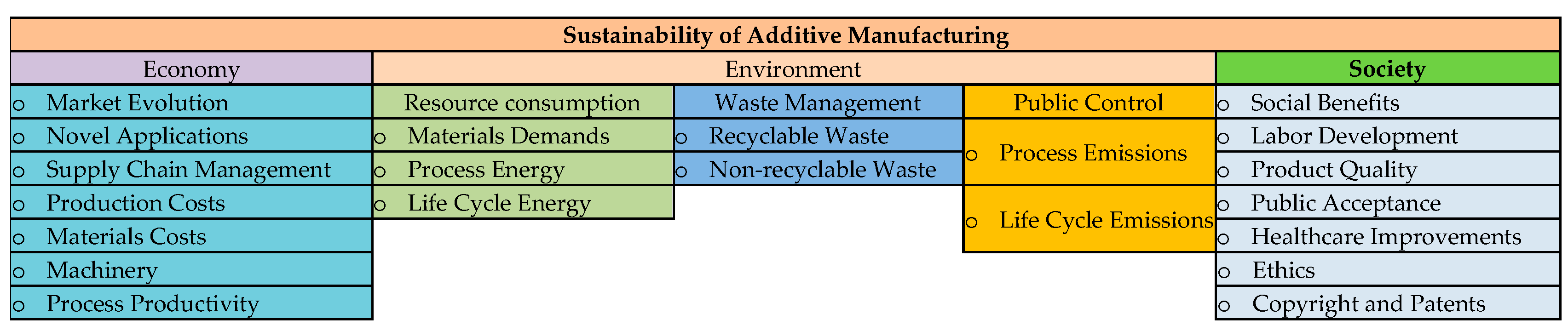
2.6. Sustainability
3. Discussion
3.1. DfAM Guidelines
3.2. DfAM Tools
4. Conclusions
Author Contributions
Funding
Acknowledgments
Conflicts of Interest
References
- ASTM International. Standard Terminology for Additive Manufacturing Technologies; ASTM International F2792-12a; ASTM International: West Conshohocken, PA, USA, 2012. [Google Scholar]
- Pham, D.T.; Gault, R.S. A comparison of rapid prototyping technologies. Int. J. Mach. Tools Manuf. 1998, 38, 1257–1287. [Google Scholar]
- Thompson, M.K.; Moroni, G.; Vaneker, T.; Fadel, G.; Campbell, R.I.; Gibson, I.; Bernard, A.; Schulz, J.; Graf, P.; Ahuja, B. Design for Additive Manufacturing: Trends, opportunities, considerations, and constraints. CIRP Ann. 2016, 65, 737–760. [Google Scholar]
- Medellin-Castillo, H.I.; Zaragoza-Siqueiros, J. Design and Manufacturing Strategies for Fused Deposition Modelling in Additive Manufacturing: A Review. Chin. J. Mech. Eng. 2019, 32, 53. [Google Scholar]
- Vayre, B.; Vignat, F.; Villeneuve, F. Designing for additive manufacturing. Procedia CIRP 2012, 3, 632–637. [Google Scholar]
- Giannatsis, J.; Dedoussis, V. Additive fabrication technologies applied to medicine and health care: A review. Int. J. Adv. Manuf. Technol. 2009, 40, 116–127. [Google Scholar]
- Sachlos, E.; Czernuszka, J. Making tissue engineering scaffolds work. Review: The application of solid freeform fabrication technology to the production of tissue engineering scaffolds. Eur. Cells Mater. 2003, 5, 39–40. [Google Scholar]
- Thomas, C.L.; Gaffney, T.M.; Kaza, S.; Lee, C.H. Rapid prototyping of large scale aerospace structures. In Proceedings of the 1996 IEEE Aerospace Applications Conference, Aspen, CO, USA, 10 February 1996; pp. 219–230. [Google Scholar]
- Song, Y.; Yan, Y.; Zhang, R.; Xu, D.; Wang, F. Manufacture of the die of an automobile deck part based on rapid prototyping and rapid tooling technology. J. Mater. Process. Technol. 2002, 120, 237–242. [Google Scholar]
- Melchels, F.P.; Feijen, J.; Grijpma, D.W. A review on stereolithography and its applications in biomedical engineering. Biomaterials 2010, 31, 6121–6130. [Google Scholar]
- Beaman, J.J.; Barlow, J.W.; Bourell, D.L.; Crawford, R.H.; Marcus, H.L.; McAlea, K.P. Solid freeform fabrication: A new direction in manufacturing. Kluwer Acad. Publ. Norwell Ma 1997, 2061, 25–49. [Google Scholar]
- Comb, J.; Priedeman, W.; Turley, P.W. FDM® Technology process improvements. In Proceedings of the 1994 International Solid Freeform Fabrication Symposium, UT Austin, TX, USA, 8–10 June 1994; pp. 42–49. [Google Scholar]
- Sachs, E.M.; Haggerty, J.S.; Cima, M.J.; Williams, P.A. Three-Dimensional Printing Techniques. Google Patents No. 5,204,055, 20 April 1993. [Google Scholar]
- Feygin, M.; Hsieh, B. Laminated object manufacturing (LOM): A simpler process. In Proceedings of the 1991 International Solid Freeform Fabrication Symposium, UT Austin, TX, USA, 12–14 August 1991; pp. 123–130. [Google Scholar] [CrossRef]
- Mazumder, J.; Schifferer, A.; Choi, J. Direct materials deposition: Designed macro and microstructure. Mater. Res. Innov. 1999, 3, 118–131. [Google Scholar]
- Laverne, F.; Segonds, F.; Anwer, N.; Le Coq, M. DFAM in the design process: A proposal of classification to foster early design stages. In Proceedings of the Confere 2014 Croatie, Sibenik, Croatia, 3–4 April 2014. [Google Scholar]
- Edgar, J.; Tint, S. Additive manufacturing technologies: 3D printing, rapid prototyping, and direct digital manufacturing. Johns. Matthey Technol. Rev. 2015, 59, 193–198. [Google Scholar] [CrossRef]
- Ko, H.; Moon, S.K.; Hwang, J. Design for additive manufacturing in customized products. Int. J. Precis. Eng. Manuf. 2015, 16, 2369–2375. [Google Scholar] [CrossRef]
- Zhang, K.; Cheng, G. Three-dimensional high resolution topology optimization considering additive manufacturing constraints. Addit. Manuf. 2020, 35, 101224. [Google Scholar] [CrossRef]
- Ameen, W.; Al-Ahmari, A.; Abdulhameed, O. Design for metal additive manufacturing: An investigation of key design application on electron beam melting. Int. J. Mech. Aerosp. Ind. Mechatron. Manuf. Eng. 2019, 13, 264–269. [Google Scholar]
- Zhang, W.; Zhou, L. Topology optimization of self-supporting structures with polygon features for additive manufacturing. Comput. Methods Appl. Mech. Eng. 2018, 334, 56–78. [Google Scholar] [CrossRef]
- Zhang, K.; Cheng, G.; Xu, L. Topology optimization considering overhang constraint in additive manufacturing. Comput. Struct. 2019, 212, 86–100. [Google Scholar] [CrossRef]
- Xiong, Y.; Yao, S.; Zhao, Z.-L.; Xie, Y.M. A new approach to eliminating enclosed voids in topology optimization for additive manufacturing. Addit. Manuf. 2020, 32, 101006. [Google Scholar] [CrossRef]
- Peng, H.; Ghasri-Khouzani, M.; Gong, S.; Attardo, R.; Ostiguy, P.; Rogge, R.B.; Gatrell, B.A.; Budzinski, J.; Tomonto, C.; Neidig, J. Fast prediction of thermal distortion in metal powder bed fusion additive manufacturing: Part 2, a quasi-static thermo-mechanical model. Addit. Manuf. 2018, 22, 869–882. [Google Scholar] [CrossRef]
- Dapogny, C.; Estevez, R.; Faure, A.; Michailidis, G. Shape and topology optimization considering anisotropic features induced by additive manufacturing processes. Comput. Methods Appl. Mech. Eng. 2019, 344, 626–665. [Google Scholar] [CrossRef] [Green Version]
- Sabiston, G.; Kim, I.Y. 3D topology optimization for cost and time minimization in additive manufacturing. Struct. Multidiscip. Optim. 2020, 61, 731–748. [Google Scholar] [CrossRef]
- Adam, G.A.; Zimmer, D. Design for Additive Manufacturing—Element transitions and aggregated structures. CIRP J. Manuf. Sci. Technol. 2014, 7, 20–28. [Google Scholar] [CrossRef]
- Gibson, L.J.; Ashby, M.F. Cellular Solids: Structure and Properties; Cambridge University Press: Cambridge, UK, 1999. [Google Scholar]
- Fielding, G.A.; Bandyopadhyay, A.; Bose, S. Effects of silica and zinc oxide doping on mechanical and biological properties of 3D printed tricalcium phosphate tissue engineering scaffolds. Dent. Mater. 2012, 28, 113–122. [Google Scholar] [CrossRef] [PubMed] [Green Version]
- Kamm, R.D. Cellular fluid mechanics. Annu. Rev. Fluid Mech. 2002, 34, 211–232. [Google Scholar] [CrossRef] [PubMed]
- Launey, M.E.; Buehler, M.J.; Ritchie, R.O. On the mechanistic origins of toughness in bone. Annu. Rev. Mater. Res. 2010, 40, 25–53. [Google Scholar] [CrossRef] [Green Version]
- Gibson, L. The hierarchical structure and mechanics of plant materials. J. R. Soc. Interface 2012, 9, 2749–2766. [Google Scholar] [CrossRef]
- Saranathan, V.; Osuji, C.O.; Mochrie, S.G.; Noh, H.; Narayanan, S.; Sandy, A.; Dufresne, E.R.; Prum, R.O. Structure, function, and self-assembly of single network gyroid (I4132) photonic crystals in butterfly wing scales. Proc. Natl. Acad. Sci. USA 2010, 107, 11676–11681. [Google Scholar] [CrossRef] [Green Version]
- Aspden, R.M. Structural basis of dilatation of the cervix. In Connective Tissue Matrix; Springer: Berlin/Heidelberg, Germany, 1990; pp. 199–228. [Google Scholar]
- Hayes, A.M.; Wang, A.; Dempsey, B.M.; McDowell, D.L. Mechanics of linear cellular alloys. Mech. Mater. 2004, 36, 691–713. [Google Scholar] [CrossRef]
- Nazir, A.; Abate, K.M.; Kumar, A.; Jeng, J.-Y. A state-of-the-art review on types, design, optimization, and additive manufacturing of cellular structures. Int. J. Adv. Manuf. Technol. 2019, 104, 3489–3510. [Google Scholar] [CrossRef]
- Chu, C.; Graf, G.; Rosen, D.W. Design for additive manufacturing of cellular structures. Comput. Aided Des. Appl. 2008, 5, 686–696. [Google Scholar] [CrossRef] [Green Version]
- Tamburrino, F.; Graziosi, S.; Bordegoni, M. The design process of additively manufactured mesoscale lattice structures: A review. J. Comput. Inf. Sci. Eng. 2018, 18, 040801. [Google Scholar] [CrossRef]
- Bi, S.; Chen, E.; Gaitanaros, S. Additive manufacturing and characterization of brittle foams. Mech. Mater. 2020, 145, 103368. [Google Scholar] [CrossRef]
- Yap, Y.L.; Yeong, W.Y. Shape recovery effect of 3D printed polymeric honeycomb: This paper studies the elastic behaviour of different honeycomb structures produced by PolyJet technology. Virtual Phys. Prototyp. 2015, 10, 91–99. [Google Scholar] [CrossRef]
- Sienkiewicz, J.; Płatek, P.; Jiang, F.; Sun, X.; Rusinek, A. Investigations on the Mechanical Response of Gradient Lattice Structures Manufactured via SLM. Metals 2020, 10, 213. [Google Scholar] [CrossRef] [Green Version]
- Opgenoord, M.M.; Willcox, K.E. Design for additive manufacturing: Cellular structures in early-stage aerospace design. Struct. Multidiscip. Optim. 2019, 60, 411–428. [Google Scholar] [CrossRef]
- Wang, A.-J.; McDowell, D. Yield surfaces of various periodic metal honeycombs at intermediate relative density. Int. J. Plast. 2005, 21, 285–320. [Google Scholar] [CrossRef]
- Deshpande, V.; Fleck, N.A.; Ashby, M.F. Effective properties of the octettruss lattice material. J. Mech. Phys. Solids 2001, 49, 1747–1769. [Google Scholar] [CrossRef] [Green Version]
- Evans, A.G.; Hutchinson, J.W.; Fleck, N.A.; Ashby, M.; Wadley, H. The topological design of multifunctional cellular metals. Prog. Mater. Sci. 2001, 46, 309–327. [Google Scholar] [CrossRef]
- Fleck, N.A. An overview of the mechanical properties of foams and periodic lattice materials. Cell Met Polym 2004, 3–7. [Google Scholar]
- Flores, I.; Kretzschmar, N.; Azman, A.H.; Chekurov, S.; Pedersen, D.B.; Chaudhuri, A. Implications of lattice structures on economics and productivity of metal powder bed fusion. Addit. Manuf. 2020, 31, 100947. [Google Scholar] [CrossRef]
- Mun, J.; Yun, B.-G.; Ju, J.; Chang, B.-M. Indirect additive manufacturing based casting of a periodic 3D cellular metal–flow simulation of molten aluminum alloy. J. Manuf. Process. 2015, 17, 28–40. [Google Scholar] [CrossRef]
- Queheillalt, D.T.; Wadley, H.N. Cellular metal lattices with hollow trusses. Acta Mater. 2005, 53, 303–313. [Google Scholar] [CrossRef]
- Dong, L.; Deshpande, V.; Wadley, H. Mechanical response of Ti–6Al–4V octet-truss lattice structures. Int. J. Solids Struct. 2015, 60, 107–124. [Google Scholar] [CrossRef]
- Wadley, H.N.; Fleck, N.A.; Evans, A.G. Fabrication and structural performance of periodic cellular metal sandwich structures. Compos. Sci. Technol. 2003, 63, 2331–2343. [Google Scholar] [CrossRef]
- Vayre, B.; Vignat, F.; Villeneuve, F. Metallic additive manufacturing: State-of-the-art review and prospects. Mech. Ind. 2012, 13, 89–96. [Google Scholar] [CrossRef]
- Rezayat, H.; Bell, J.R.; Plotkowski, A.J.; Babu, S.S. Multi-solution nature of topology optimization and its application in design for additive manufacturing. Rapid Prototyp. J. 2018, 25, 1475–1481. [Google Scholar] [CrossRef]
- Huang, Y.; Leu, M.C.; Mazumder, J.; Donmez, A. Additive manufacturing: Current state, future potential, gaps and needs, and recommendations. J. Manuf. Sci. Eng. 2015, 137, 014001. [Google Scholar] [CrossRef] [Green Version]
- Azman, A.; Vignat, F.; Villeneuve, F. Evaluating current CAD tools performances in the context of design for additive manufacturing. In Proceedings of the Joint Conference on Mechanical, Design Engineering & Advanced Manufacturing, Toulouse, France, 18–20 June 2014; pp. 1–7. [Google Scholar]
- Petschenka, G.; Agrawal, A.A. How herbivores coopt plant defenses: Natural selection, specialization, and sequestration. Curr. Opin. Insect Sci. 2016, 14, 17–24. [Google Scholar] [CrossRef]
- Doubrovski, E.; Verlinden, J.C.; Horvath, I. First steps towards collaboratively edited design for additive manufacturing knowledge. In Proceedings of the Solid Freeform Fabrication Symposium, Austin, TX, USA, 6–8 August 2012; pp. 891–901. [Google Scholar]
- Hascoet, J.; Ponche, R.; Kerbrat, O.; Mognol, P. From functional specifications to optimized CAD model: Proposition of a new DFAM methodology. In Proceedings of the ASME Design Engineering Technical Conferences and Computers and Information in Engineering Conference, Washington, DC, USA, 28–31 August 2011; pp. 467–472. [Google Scholar]
- Ponche, R.; Kerbrat, O.; Mognol, P.; Hascoet, J.-Y. A novel methodology of design for Additive Manufacturing applied to Additive Laser Manufacturing process. Robot. Comput. Integr. Manuf. 2014, 30, 389–398. [Google Scholar] [CrossRef] [Green Version]
- Seepersad, C.C. Challenges and opportunities in design for additive manufacturing. 3D Print. Addit. Manuf. 2014, 1, 10–13. [Google Scholar] [CrossRef]
- Bendsøe, M.P.; Sigmund, O. Topology optimization by distribution of isotropic material. In Topology Optimization; Springer: Berlin/Heidelberg, Germany, 2004; pp. 1–69. [Google Scholar]
- Zhao, J.; Zhang, M.; Zhu, Y.; Li, X.; Wang, L.; Hu, J. A novel optimization design method of additive manufacturing oriented porous structures and experimental validation. Mater. Des. 2019, 163, 107550. [Google Scholar] [CrossRef]
- Li, D.; Liao, W.; Dai, N.; Dong, G.; Tang, Y.; Xie, Y.M. Optimal design and modeling of gyroid-based functionally graded cellular structures for additive manufacturing. Comput. Aided Des. 2018, 104, 87–99. [Google Scholar] [CrossRef]
- Nguyen, C.H.P.; Kim, Y.; Choi, Y. Design for Additive Manufacturing of Functionally Graded Lattice Structures: A Design Method with Process Induced Anisotropy Consideration. Int. J. Precis. Eng. Manuf. Green Technol. 2019, 7, 1–17. [Google Scholar] [CrossRef]
- Kuo, Y.-H.; Cheng, C.-C. Self-supporting structure design for additive manufacturing by using a logistic aggregate function. Struct. Multidiscip. Optim. 2019, 60, 1109–1121. [Google Scholar] [CrossRef]
- Merulla, A.; Gatto, A.; Bassoli, E.; Munteanu, S.I.; Gheorghiu, B.; Pop, M.A.; Bedo, T.; Munteanu, D. Weight reduction by topology optimization of an engine subframe mount, designed for additive manufacturing production. Mater. Today Proc. 2019, 19, 1014–1018. [Google Scholar] [CrossRef]
- Langelaar, M. Integrated component-support topology optimization for additive manufacturing with post-machining. Rapid Prototyp. J. 2019, 25, 255–265. [Google Scholar] [CrossRef] [Green Version]
- Sigmund, O. A new class of extremal composites. J. Mech. Phys. Solids 2000, 48, 397–428. [Google Scholar] [CrossRef]
- Sigmund, O.; Torquato, S. Composites with extremal thermal expansion coefficients. Appl. Phys. Lett. 1996, 69, 3203–3205. [Google Scholar] [CrossRef]
- Li, H.; Luo, Z.; Gao, L.; Qin, Q. Topology optimization for concurrent design of structures with multi-patch microstructures by level sets. Comput. Methods Appl. Mech. Eng. 2018, 331, 536–561. [Google Scholar] [CrossRef]
- Sigmund, O. Materials with prescribed constitutive parameters: An inverse homogenization problem. Int. J. Solids Struct. 1994, 31, 2313–2329. [Google Scholar] [CrossRef]
- Wicks, N.; Guest, S. Single member actuation in large repetitive truss structures. Int. J. Solids Struct. 2004, 41, 965–978. [Google Scholar] [CrossRef]
- Zhu, Z.; Anwer, N.; Mathieu, L. Deviation modeling and shape transformation in design for additive manufacturing. Procedia CIRP 2017, 60, 211–216. [Google Scholar] [CrossRef]
- Savio, G.; Meneghello, R.; Concheri, G. Geometric modeling of lattice structures for additive manufacturing. Rapid Prototyp. J. 2018, 24, 351–360. [Google Scholar] [CrossRef]
- Giannitelli, S.M.; Accoto, D.; Trombetta, M.; Rainer, A. Current trends in the design of scaffolds for computer-aided tissue engineering. Acta Biomater. 2014, 10, 580–594. [Google Scholar] [CrossRef] [PubMed]
- Wauthle, R.; Vrancken, B.; Beynaerts, B.; Jorissen, K.; Schrooten, J.; Kruth, J.-P.; Van Humbeeck, J. Effects of build orientation and heat treatment on the microstructure and mechanical properties of selective laser melted Ti6Al4V lattice structures. Addit. Manuf. 2015, 5, 77–84. [Google Scholar] [CrossRef]
- Ahmadi, S.M.; Yavari, S.A.; Wauthle, R.; Pouran, B.; Schrooten, J.; Weinans, H.; Zadpoor, A.A. Additively manufactured open-cell porous biomaterials made from six different space-filling unit cells: The mechanical and morphological properties. Materials 2015, 8, 1871–1896. [Google Scholar] [CrossRef] [Green Version]
- Zheng, X.; Lee, H.; Weisgraber, T.H.; Shusteff, M.; DeOtte, J.; Duoss, E.B.; Kuntz, J.D.; Biener, M.M.; Ge, Q.; Jackson, J.A. Ultralight, ultrastiff mechanical metamaterials. Science 2014, 344, 1373–1377. [Google Scholar] [CrossRef] [Green Version]
- Bückmann, T.; Schittny, R.; Thiel, M.; Kadic, M.; Milton, G.W.; Wegener, M. On three-dimensional dilational elastic metamaterials. New J. Phys. 2014, 16, 033032. [Google Scholar] [CrossRef] [Green Version]
- Hengsbach, S.; Lantada, A.D. Direct laser writing of auxetic structures: Present capabilities and challenges. Smart Mater. Struct. 2014, 23, 085033. [Google Scholar] [CrossRef]
- Schwerdtfeger, J.; Wein, F.; Leugering, G.; Singer, R.; Körner, C.; Stingl, M.; Schury, F. Design of auxetic structures via mathematical optimization. Adv. Mater. 2011, 23, 2650–2654. [Google Scholar] [CrossRef]
- Babaee, S.; Shim, J.; Weaver, J.C.; Chen, E.R.; Patel, N.; Bertoldi, K. Metamaterials: 3D Soft Metamaterials with Negative Poisson’s Ratio. Adv. Mater. 2013, 25, 5116. [Google Scholar] [CrossRef]
- Kolla, A.; Ju, J.; Summers, J.D.; Fadel, G.; Ziegert, J.C. Design of chiral honeycomb meso-structures for high shear flexure. In Proceedings of the ASME 2010 International Design Engineering Technical Conferences and Computers and Information in Engineering Conference, Montreal, QC, Canada, 15–18 August 2010; pp. 43–49. [Google Scholar]
- Xie, Y.; Konneker, A.; Popa, B.-I.; Cummer, S.A. Tapered labyrinthine acoustic metamaterials for broadband impedance matching. Appl. Phys. Lett. 2013, 103, 201906. [Google Scholar] [CrossRef] [Green Version]
- Lakes, R. Materials with structural hierarchy. Nature 1993, 361, 511–515. [Google Scholar] [CrossRef]
- Ashby, M.F.; Evans, T.; Fleck, N.A.; Hutchinson, J.; Wadley, H.; Gibson, L. Metal Foams: A Design Guide; Elsevier: Amsterdam, The Netherlands, 2000. [Google Scholar]
- Snelling, D.; Li, Q.; Meisel, N.; Williams, C.B.; Batra, R.C.; Druschitz, A.P. Lightweight metal cellular structures fabricated via 3D printing of sand cast molds. Adv. Eng. Mater. 2015, 17, 923–932. [Google Scholar] [CrossRef]
- Tang, Y.; Zhou, Y.; Hoff, T.; Garon, M.; Zhao, Y. Elastic modulus of 316 stainless steel lattice structure fabricated via binder jetting process. Mater. Sci. Technol. 2016, 32, 648–656. [Google Scholar] [CrossRef]
- Druschitz, A.; Williams, C.; Snelling, D.; Seals, M. Additive manufacturing supports the production of complex castings. In Shape Casting: 5th International Symposium, The Minerals, Metals & Materials Society; Springer: Cham, Switzerland, 2014; pp. 51–57. [Google Scholar]
- Leach, A. The thermal conductivity of foams. I. Models for heat conduction. J. Phys. D Appl. Phys. 1993, 26, 733. [Google Scholar] [CrossRef]
- Nazir, A.; Jeng, J.-Y. Buckling behavior of additively manufactured cellular columns: Experimental and simulation validation. Mater. Des. 2020, 186, 108349. [Google Scholar] [CrossRef]
- Nazir, A.; Arshad, A.B.; Jeng, J.-Y. Buckling and Post-Buckling Behavior of Uniform and Variable-Density Lattice Columns Fabricated Using Additive Manufacturing. Materials 2019, 12, 3539. [Google Scholar] [CrossRef] [Green Version]
- Cheng, L.; Zhang, P.; Biyikli, E.; Bai, J.; Robbins, J.; To, A. Efficient design optimization of variable-density cellular structures for additive manufacturing: Theory and experimental validation. Rapid Prototyp. J. 2017, 23, 660–677. [Google Scholar] [CrossRef]
- Nguyen, J.; Park, S.-I.; Rosen, D. Heuristic optimization method for cellular structure design of light weight components. Int. J. Precis. Eng. Manuf. 2013, 14, 1071–1078. [Google Scholar] [CrossRef]
- Teufelhart, S.; Reinhart, G. Optimization of strut diameters in lattice structures. In Proceedings of the 23rd Solid Freeform Fabrication (SFF) Symposium, Austin, TX, USA, 6–8 August 2012; pp. 719–733. [Google Scholar]
- Israel, M. The suitability of analytical and numerical methods for developing clinching processes with thick sheet metal. Adv. Mater. Res. 2014, 907, 151–163. [Google Scholar] [CrossRef]
- Maheshwaraa, U.; Bourell, D.; Seepersad, C.C. Design and freeform fabrication of deployable structures with lattice skins. Rapid Prototyp. J. 2007, 13, 213–225. [Google Scholar] [CrossRef] [Green Version]
- Namasivayam, U.M.; Seepersad, C.C. Topology design and freeform fabrication of deployable structures with lattice skins. Rapid Prototyp. J. 2011, 17, 5–16. [Google Scholar] [CrossRef]
- Paz Hernández, R.; Monzón Verona, M.D.; González Landín, B.; Pei, E.; Winter Althaus, G.; Ortega García, F. Lightweight parametric optimisation method for cellular structures in additive manufactured parts. Int. J. Simul. Multidiscip. Des. Optim. 2016, 7, A6. [Google Scholar] [CrossRef] [Green Version]
- Dakshnamoorthy, V. Automated Lattice Optimization of Hinge Fitting with Displacement Constraint. Ph.D. Thesis, The University of Texas, Austin, TX, USA, 2016. [Google Scholar]
- Banhart, J. Progress in Materials Science. Manuf. Chraracterisation Appl. Cell. Met. Met. Foam. 2001, 46, 559–632. [Google Scholar]
- Sundararajan, V.G. Topology Optimization for Additive Manufacturing of Customized Meso-Structures Using Homogenization and Parametric Smoothing Functions. Ph.D. Thesis, The University of Texas at Austin, Austin, TX, USA, 2010. [Google Scholar]
- Sutradhar, A.; Park, J.; Carrau, D.; Miller, M.J. Experimental validation of 3D printed patient-specific implants using digital image correlation and finite element analysis. Comput. Biol. Med. 2014, 52, 8–17. [Google Scholar] [CrossRef] [PubMed]
- Sutradhar, A.; Paulino, G.H.; Miller, M.J.; Nguyen, T.H. Topological optimization for designing patient-specific large craniofacial segmental bone replacements. Proc. Natl. Acad. Sci. USA 2010, 107, 13222–13227. [Google Scholar] [CrossRef] [PubMed] [Green Version]
- Arafat, M.T.; Gibson, I.; Li, X. State of the art and future direction of additive manufactured scaffolds-based bone tissue engineering. Rapid Prototyp. J. 2014, 20, 13–26. [Google Scholar] [CrossRef]
- Armillotta, A.; Pelzer, R. Modeling of porous structures for rapid prototyping of tissue engineering scaffolds. Int. J. Adv. Manuf. Technol. 2008, 39, 501–511. [Google Scholar] [CrossRef]
- Ohldin, P. Series production of CE-certified orthopedic implants with integrated porous structures for improved bone ingrowth. In Proceedings of the 21st International DAAAM Symposium, Zadar, Croatia, 20–23 October 2010; pp. 1585–1587. [Google Scholar]
- Dias, M.R.; Guedes, J.M.; Flanagan, C.L.; Hollister, S.J.; Fernandes, P.R. Optimization of scaffold design for bone tissue engineering: A computational and experimental study. Med Eng. Phys. 2014, 36, 448–457. [Google Scholar] [CrossRef]
- Hutmacher, D.W. Scaffolds in tissue engineering bone and cartilage. Biomaterials 2000, 21, 2529–2543. [Google Scholar] [CrossRef]
- Lanzotti, A.; Martorelli, M.; Russo, T.; Gloria, A. Design of Additively Manufactured Lattice Structures for Tissue Regeneration. Mater. Sci. Forum 2018, 941, 2154–2159. [Google Scholar] [CrossRef]
- Dabrowski, B.; Swieszkowski, W.; Godlinski, D.; Kurzydlowski, K.J. Highly porous titanium scaffolds for orthopaedic applications. J. Biomed. Mater. Res. Part B Appl. Biomater. 2010, 95, 53–61. [Google Scholar] [CrossRef] [PubMed]
- Cooper, L.F. A role for surface topography in creating and maintaining bone at titanium endosseous implants. J. Prosthet. Dent. 2000, 84, 522–534. [Google Scholar] [CrossRef] [PubMed]
- Azman, A.H.; Vignat, F.; Villeneuve, F. CAD tools and file format performance evaluation in designing lattice structures for additive manufacturing. J. Teknol. 2018, 80, 87–95. [Google Scholar] [CrossRef] [Green Version]
- Stolt, R.; Heikkinen, T.; Elgh, F. Integrating Additive Manufacturing in the Design of Aerospace Components. In Proceedings of the 25th ISPE International Conference on Transdisciplinary Engineering Integrating (TE2018), Modena, Italy, 3–6 July 2018; pp. 145–154. [Google Scholar]
- Di Caprio, F.; Acanfora, V.; Franchitti, S.; Sellitto, A.; Riccio, A. Hybrid metal/composite lattice structures: Design for additive manufacturing. Aerospace 2019, 6, 71. [Google Scholar] [CrossRef] [Green Version]
- Lebaal, N.; Zhang, Y.; Demoly, F.; Roth, S.; Gomes, S.; Bernard, A. Optimised lattice structure configuration for additive manufacturing. CIRP Ann. 2019, 68, 117–120. [Google Scholar] [CrossRef]
- Syam, W.P.; Jianwei, W.; Zhao, B.; Maskery, I.; Elmadih, W.; Leach, R. Design and analysis of strut-based lattice structures for vibration isolation. Precis. Eng. 2018, 52, 494–506. [Google Scholar] [CrossRef]
- Boothroyd, G. Product design for manufacture and assembly. Comput. Aided Des. 1994, 26, 505–520. [Google Scholar] [CrossRef]
- Yang, S.; Tang, Y.; Zhao, Y.F. Assembly-level design for additive manufacturing: Issues and benchmark. In Proceedings of the ASME 2016 International Design Engineering Technical Conferences and Computers and Information in Engineering Conference, Charlotte, NC, USA, 21–24 August 2016. [Google Scholar]
- Yang, S.; Zhao, Y.F. Additive manufacturing-enabled design theory and methodology: A critical review. Int. J. Adv. Manuf. Technol. 2015, 80, 327–342. [Google Scholar] [CrossRef]
- Schmelzle, J.; Kline, E.V.; Dickman, C.J.; Reutzel, E.W.; Jones, G.; Simpson, T.W. (Re) Designing for part consolidation: Understanding the challenges of metal additive manufacturing. J. Mech. Des. 2015, 137, 13. [Google Scholar] [CrossRef]
- Dietrich, D.M.; Cudney, E. Impact of integrative design on additive manufacturing quality. Int. J. Rapid Manuf. 2011, 2, 121–131. [Google Scholar] [CrossRef]
- Kumke, M.; Watschke, H.; Vietor, T. A new methodological framework for design for additive manufacturing. Virtual Phys. Prototyp. 2016, 11, 3–19. [Google Scholar] [CrossRef]
- Yang, S.; Talekar, T.; Sulthan, M.A.; Zhao, Y.F. A generic sustainability assessment model towards consolidated parts fabricated by additive manufacturing process. Procedia Manuf. 2017, 10, 831–844. [Google Scholar] [CrossRef]
- Kellner, T. An epiphany of disruption: GE additive chief explains how 3D printing will upend manufacturing. GE Rep. 2017, 13. Available online: https://www.ge.com/reports/epiphany-disruption-ge-additive-chief-explains-3d-printing-will-upend-manufacturing/ (accessed on 19 May 2020).
- Gibson, I.; Rosen, D.W.; Stucker, B. Design for additive manufacturing. In Additive Manufacturing Technologies; Springer: Berlin/Heidelberg, Germany, 2010; pp. 299–332. [Google Scholar]
- Yang, S.; Min, W.; Ghibaudo, J.; Zhao, Y.F. Understanding the sustainability potential of part consolidation design supported by additive manufacturing. J. Clean. Prod. 2019, 232, 722–738. [Google Scholar] [CrossRef]
- Oh, Y.; Behdad, S.; Zhou, C. Part Separation Methods for Assembly Based Design in Additive Manufacturing. In Proceedings of the ASME 2017 International Design Engineering Technical Conferences and Computers and Information in Engineering Conference, Cleveland, OH, USA, 6–9 August 2017. [Google Scholar]
- Yao, X.; Moon, S.K.; Bi, G. A cost-driven design methodology for additive manufactured variable platforms in product families. J. Mech. Des. 2016, 138, 4. [Google Scholar] [CrossRef]
- Lei, N.; Yao, X.; Moon, S.K.; Bi, G. An additive manufacturing process model for product family design. J. Eng. Des. 2016, 27, 751–767. [Google Scholar] [CrossRef]
- Tang, Y.; Zhao, Y.F. A survey of the design methods for additive manufacturing to improve functional performance. Rapid Prototyp. J. 2016, 22, 569–590. [Google Scholar] [CrossRef]
- Dinar, M.; Rosen, D.W. A design for additive manufacturing ontology. J. Comput. Inf. Sci. Eng. 2017, 17, 2. [Google Scholar] [CrossRef]
- Rosen, D.W. Computer-aided design for additive manufacturing of cellular structures. Comput. Aided Des. Appl. 2007, 4, 585–594. [Google Scholar] [CrossRef]
- Campbell, I.; Diegel, O.; Kowen, J.; Wohlers, T. Wohlers Report 2018: 3D Printing and Additive Manufacturing State of the Industry: Annual Worldwide Progress Report; Wohlers Associates: Fort Collins, CO, USA, 2018. [Google Scholar]
- Rosen, D.W. Design for additive manufacturing: A method to explore unexplored regions of the design space. In Proceedings of the 2007 International Solid Freeform Fabrication Symposium, Austin, TX, USA, 6–8 August 2007; pp. 402–415. [Google Scholar]
- Rosen, D.W.; Seepersad, C.C.; Simpson, T.W.; Williams, C.B. Design for additive manufacturing: A paradigm shift in design, fabrication, and qualification. J. Mech. Des. 2015, 137, 11. [Google Scholar] [CrossRef]
- Yang, S.; Santoro, F.; Zhao, Y.F. Towards a numerical approach of finding candidates for additive manufacturing-enabled part consolidation. J. Mech. Des. 2018, 140, 4. [Google Scholar] [CrossRef]
- Liu, J. Guidelines for AM part consolidation. Virtual Phys. Prototyp. 2016, 11, 133–141. [Google Scholar] [CrossRef]
- Ngo, T.D.; Kashani, A.; Imbalzano, G.; Nguyen, K.T.; Hui, D. Additive manufacturing (3D printing): A review of materials, methods, applications and challenges. Compos. Part B Eng. 2018, 143, 172–196. [Google Scholar] [CrossRef]
- Carlton, H.D.; Haboub, A.; Gallegos, G.F.; Parkinson, D.Y.; MacDowell, A.A. Damage evolution and failure mechanisms in additively manufactured stainless steel. Mater. Sci. Eng. A 2016, 651, 406–414. [Google Scholar] [CrossRef] [Green Version]
- Casalino, G.; Campanelli, S.; Contuzzi, N.; Ludovico, A. Experimental investigation and statistical optimisation of the selective laser melting process of a maraging steel. Opt. Laser Technol. 2015, 65, 151–158. [Google Scholar] [CrossRef]
- Murr, L.E.; Martinez, E.; Hernandez, J.; Collins, S.; Amato, K.N.; Gaytan, S.M.; Shindo, P.W. Microstructures and properties of 17-4 PH stainless steel fabricated by selective laser melting. J. Mater. Res. Technol. 2012, 1, 167–177. [Google Scholar] [CrossRef] [Green Version]
- Mazumder, J.; Choi, J.; Nagarathnam, K.; Koch, J.; Hetzner, D. The direct metal deposition of H13 tool steel for 3-D components. JOM 1997, 49, 55–60. [Google Scholar] [CrossRef]
- Brice, C.; Shenoy, R.; Kral, M.; Buchannan, K. Precipitation behavior of aluminum alloy 2139 fabricated using additive manufacturing. Mater. Sci. Eng. A 2015, 648, 9–14. [Google Scholar] [CrossRef]
- Bartkowiak, K.; Ullrich, S.; Frick, T.; Schmidt, M. New developments of laser processing aluminium alloys via additive manufacturing technique. Phys. Procedia 2011, 12, 393–401. [Google Scholar] [CrossRef] [Green Version]
- Sheydaeian, E.; Toyserkani, E. A new approach for fabrication of titanium-titanium boride periodic composite via additive manufacturing and pressure-less sintering. Compos. Part B Eng. 2018, 138, 140–148. [Google Scholar] [CrossRef]
- Hu, Y.; Cong, W.; Wang, X.; Li, Y.; Ning, F.; Wang, H. Laser deposition-additive manufacturing of TiB-Ti composites with novel three-dimensional quasi-continuous network microstructure: Effects on strengthening and toughening. Compos. Part B Eng. 2018, 133, 91–100. [Google Scholar] [CrossRef]
- Attar, H.; Calin, M.; Zhang, L.; Scudino, S.; Eckert, J. Manufacture by selective laser melting and mechanical behavior of commercially pure titanium. Mater. Sci. Eng. A 2014, 593, 170–177. [Google Scholar] [CrossRef]
- Vaithilingam, J.; Kilsby, S.; Goodridge, R.D.; Christie, S.D.; Edmondson, S.; Hague, R.J. Functionalisation of Ti6Al4V components fabricated using selective laser melting with a bioactive compound. Mater. Sci. Eng. C 2015, 46, 52–61. [Google Scholar] [CrossRef]
- Yadroitsev, I.; Thivillon, L.; Bertrand, P.; Smurov, I. Strategy of manufacturing components with designed internal structure by selective laser melting of metallic powder. Appl. Surf. Sci. 2007, 254, 980–983. [Google Scholar] [CrossRef]
- Körner, C.; Helmer, H.; Bauereiß, A.; Singer, R.F. Tailoring the grain structure of IN718 during selective electron beam melting. In Proceedings of the MATEC Web of Conferences, Giens, France, 12–16 May 2014; p. 08001. [Google Scholar]
- Ligon, S.C.; Liska, R.; Stampfl, J.R.; Gurr, M.; Mulhaupt, R. Polymers for 3D printing and customized additive manufacturing. Chem. Rev. 2017, 117, 10212–10290. [Google Scholar] [CrossRef] [Green Version]
- Gundrati, N.B.; Chakraborty, P.; Zhou, C.; Chung, D. First observation of the effect of the layer printing sequence on the molecular structure of three-dimensionally printed polymer, as shown by in-plane capacitance measurement. Compos. Part B Eng. 2018, 140, 78–82. [Google Scholar] [CrossRef]
- Postiglione, G.; Natale, G.; Griffini, G.; Levi, M.; Turri, S. Conductive 3D microstructures by direct 3D printing of polymer/carbon nanotube nanocomposites via liquid deposition modeling. Compos. Part A Appl. Sci. Manuf. 2015, 76, 110–114. [Google Scholar] [CrossRef]
- Yang, J.-u.; Cho, J.H.; Yoo, M.J. Selective metallization on copper aluminate composite via laser direct structuring technology. Compos. Part B Eng. 2017, 110, 361–367. [Google Scholar] [CrossRef]
- Zhuang, Y.; Song, W.; Ning, G.; Sun, X.; Sun, Z.; Xu, G.; Zhang, B.; Chen, Y.; Tao, S. 3D–printing of materials with anisotropic heat distribution using conductive polylactic acid composites. Mater. Des. 2017, 126, 135–140. [Google Scholar] [CrossRef]
- Singh, R.; Singh, S.; Fraternali, F. Development of in-house composite wire based feed stock filaments of fused deposition modelling for wear-resistant materials and structures. Compos. Part B Eng. 2016, 98, 244–249. [Google Scholar] [CrossRef]
- Singh, R.; Singh, N.; Amendola, A.; Fraternali, F. On the wear properties of Nylon6-SiC-Al2O3 based fused deposition modelling feed stock filament. Compos. Part B Eng. 2017, 119, 125–131. [Google Scholar] [CrossRef]
- Han, Q.; Geng, Y.; Setchi, R.; Lacan, F.; Gu, D.; Evans, S.L. Macro and nanoscale wear behaviour of Al-Al2O3 nanocomposites fabricated by selective laser melting. Compos. Part B Eng. 2017, 127, 26–35. [Google Scholar] [CrossRef]
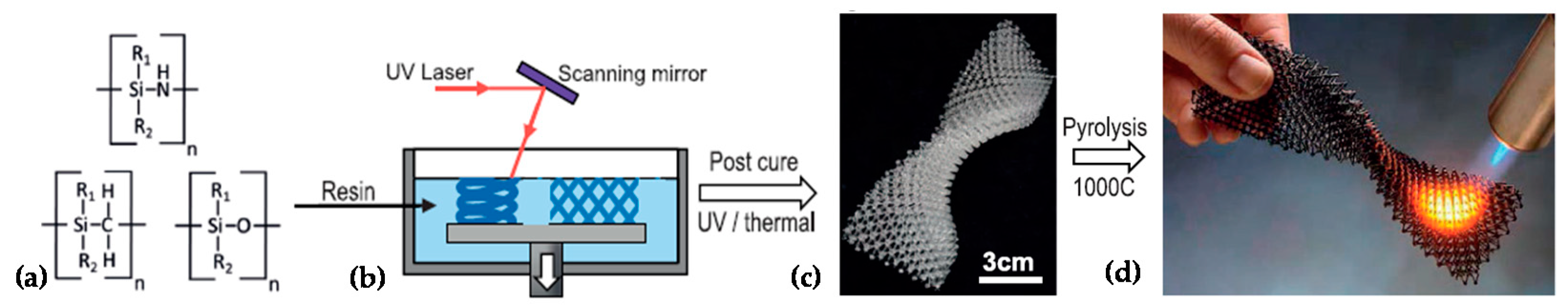
- Eckel, Z.C.; Zhou, C.; Martin, J.H.; Jacobsen, A.J.; Carter, W.B.; Schaedler, T.A. Additive manufacturing of polymer-derived ceramics. Science 2016, 351, 58–62. [Google Scholar] [CrossRef] [Green Version]
- Wolfs, R.; Bos, F.; Salet, T. Hardened properties of 3D printed concrete: The influence of process parameters on interlayer adhesion. Cem. Concr. Res. 2019, 119, 132–140. [Google Scholar] [CrossRef]
- Le, T.T.; Austin, S.A.; Lim, S.; Buswell, R.A.; Gibb, A.G.; Thorpe, T. Mix design and fresh properties for high-performance printing concrete. Mater. Struct. 2012, 45, 1221–1232. [Google Scholar] [CrossRef] [Green Version]
- Gosselin, C.; Duballet, R.; Roux, P.; Gaudillière, N.; Dirrenberger, J.; Morel, P. Large-scale 3D printing of ultra-high performance concrete–a new processing route for architects and builders. Mater. Des. 2016, 100, 102–109. [Google Scholar] [CrossRef] [Green Version]
- Paul, S.C.; Tay, Y.W.D.; Panda, B.; Tan, M.J. Fresh and hardened properties of 3D printable cementitious materials for building and construction. Arch. Civ. Mech. Eng. 2018, 18, 311–319. [Google Scholar] [CrossRef]
- Ryder, M.A.; Lados, D.A.; Iannacchione, G.S.; Peterson, A.M. Fabrication and properties of novel polymer-metal composites using fused deposition modeling. Compos. Sci. Technol. 2018, 158, 43–50. [Google Scholar] [CrossRef]
- Vaezi, M.; Chianrabutra, S.; Mellor, B.; Yang, S. Multiple material additive manufacturing–Part 1: A review: This review paper covers a decade of research on multiple material additive manufacturing technologies which can produce complex geometry parts with different materials. Virtual Phys. Prototyp. 2013, 8, 19–50. [Google Scholar] [CrossRef]
- Wang, X.; Jiang, M.; Zhou, Z.; Gou, J.; Hui, D. 3D printing of polymer matrix composites: A review and prospective. Compos. Part B Eng. 2017, 110, 442–458. [Google Scholar] [CrossRef]
- Kazemian, A.; Yuan, X.; Cochran, E.; Khoshnevis, B. Cementitious materials for construction-scale 3D printing: Laboratory testing of fresh printing mixture. Constr. Build. Mater. 2017, 145, 639–647. [Google Scholar] [CrossRef]
- Baudana, G.; Biamino, S.; Ugues, D.; Lombardi, M.; Fino, P.; Pavese, M.; Badini, C. Titanium aluminides for aerospace and automotive applications processed by Electron Beam Melting: Contribution of Politecnico di Torino. Met. Powder Rep. 2016, 71, 193–199. [Google Scholar] [CrossRef]
- Ameen, W.; Al-Ahmari, A.; Mohammed, M.K. Self-supporting overhang structures produced by additive manufacturing through electron beam melting. Int. J. Adv. Manuf. Technol. 2019, 104, 2215–2232. [Google Scholar] [CrossRef]
- Poyraz, Ö.; Yasa, E.; Akbulut, G.; Orhangul, A.; Pilatin, S. Investigation of support structures for direct metal laser sintering (DMLS) of IN625 parts. In Proceedings of the Solid Freeform Fabrication Symposium, Austin, TX, USA, 10–12 August 2015; pp. 560–574. [Google Scholar]
- Ameen, W.; Khan Mohammed, M.; Al-Ahmari, A. Evaluation of Support Structure Removability for Additively Manufactured Ti6Al4V Overhangs via Electron Beam Melting. Metals 2019, 9, 1211. [Google Scholar] [CrossRef] [Green Version]
- Strano, G.; Hao, L.; Everson, R.; Evans, K. A new approach to the design and optimisation of support structures in additive manufacturing. Int. J. Adv. Manuf. Technol. 2013, 66, 1247–1254. [Google Scholar] [CrossRef]
- Vanek, J.; Galicia, J.A.G.; Benes, B. Clever support: Efficient support structure generation for digital fabrication. Comput. Graph. Forum 2014, 33, 117–125. [Google Scholar] [CrossRef] [Green Version]
- Calignano, F. Design optimization of supports for overhanging structures in aluminum and titanium alloys by selective laser melting. Mater. Des. 2014, 64, 203–213. [Google Scholar] [CrossRef]
- Li, Z.; Zhang, D.Z.; Dong, P.; Kucukkoc, I. A lightweight and support-free design method for selective laser melting. Int. J. Adv. Manuf. Technol. 2017, 90, 2943–2953. [Google Scholar] [CrossRef] [Green Version]
- Leary, M.; Merli, L.; Torti, F.; Mazur, M.; Brandt, M. Optimal topology for additive manufacture: A method for enabling additive manufacture of support-free optimal structures. Mater. Des. 2014, 63, 678–690. [Google Scholar] [CrossRef]
- Zhang, Y.; Bernard, A.; Harik, R.; Karunakaran, K. Build orientation optimization for multi-part production in additive manufacturing. J. Intell. Manuf. 2017, 28, 1393–1407. [Google Scholar] [CrossRef]
- Canellidis, V.; Giannatsis, J.; Dedoussis, V. Genetic-algorithm-based multi-objective optimization of the build orientation in stereolithography. Int. J. Adv. Manuf. Technol. 2009, 45, 714–730. [Google Scholar] [CrossRef]
- Perrot, A. Impression 3D du Béton: État de L’art et Challenges de la Révolution de la Construction Digitale; ISTE Group: London, UK, 2019. [Google Scholar]
- Doubrovski, Z.; Verlinden, J.C.; Geraedts, J.M. Optimal design for additive manufacturing: Opportunities and challenges. In Proceedings of the ASME 2011 International Design Engineering Technical Conferences and Computers and Information in Engineering Conference, Washington, DC, USA, 28–31 August 2011; pp. 635–646. [Google Scholar]
- Bernotat, A. Cellular Loop: Ein Freischwinger, entwickelt nach dem Vorbild der Natur. Bautechnik 2013, 90, 777–782. [Google Scholar] [CrossRef]
- Salman, F.; Cui, Y.; Zafar, I.; Liu, F.; Wang, L.; Wu, W. A Wireless-controlled 3D printed Robotic Hand Motion System with Flex Force Sensors. Sens. Actuators A Phys. 2020, 309, 112004. [Google Scholar] [CrossRef]
- Jin, T. Development of Concentric Semi-Automated Manipulator for Assembly Process. Ph.D. Thesis, Universiti Putra Malaysia, Seri Kembangan, Selangor, Malaysia, 2018. [Google Scholar]
- Grzesiak, A.; Becker, R.; Verl, A. The bionic handling assistant: A success story of additive manufacturing. Assem. Autom. 2011, 1, 329–333. [Google Scholar] [CrossRef]
- Setaki, F.; Tenpierik, M.; Turrin, M.; van Timmeren, A. Acoustic absorbers by additive manufacturing. Build. Environ. 2014, 72, 188–200. [Google Scholar] [CrossRef]
- Choi, J.-W.; Yamashita, M.; Sakakibara, J.; Kaji, Y.; Oshika, T.; Wicker, R.B. Combined micro and macro additive manufacturing of a swirling flow coaxial phacoemulsifier sleeve with internal micro-vanes. Biomed. Microdevices 2010, 12, 875–886. [Google Scholar] [CrossRef]
- Altaf, K.; Rani, A.M.A.; Raghavan, V.R. Prototype production and experimental analysis for circular and profiled conformal cooling channels in aluminium filled epoxy injection mould tools. Rapid Prototyp. J. 2013, 19, 220–229. [Google Scholar] [CrossRef]
- Garcia, M.; Garcia-Pando, C.; Marto, C. Conformal cooling in moulds with special geometry. In Proceedings of the Innovative Developments in Virtual and Physical Prototyping, Leira, Portugal, 28 September–1 October 2011; pp. 409–412. [Google Scholar]
- Dapino, M.J. Smart structure integration through ultrasonic additive manufacturing. In Proceedings of the ASME 2014 Conference on Smart Materials, Adaptive Structures and Intelligent Systems, Newport, RI, USA, 8–10 September 2014. [Google Scholar]
- Hehr, A.; Dapino, M.J. Interfacial shear strength estimates of NiTi–Al matrix composites fabricated via ultrasonic additive manufacturing. Compos. Part B Eng. 2015, 77, 199–208. [Google Scholar] [CrossRef]
- Malone, E.; Rasa, K.; Cohen, D.; Isaacson, T.; Lashley, H.; Lipson, H. Freeform fabrication of zinc-air batteries and electromechanical assemblies. Rapid Prototyp. J. 2004, 10, 58–69. [Google Scholar] [CrossRef] [Green Version]
- Macdonald, E.; Salas, R.; Espalin, D.; Perez, M.; Aguilera, E.; Muse, D.; Wicker, R.B. 3D printing for the rapid prototyping of structural electronics. IEEE Access 2014, 2, 234–242. [Google Scholar] [CrossRef]
- Lopes, A.J.; MacDonald, E.; Wicker, R.B. Integrating stereolithography and direct print technologies for 3D structural electronics fabrication. Rapid Prototyp. J. 2012, 18, 129–143. [Google Scholar] [CrossRef]
- Maiwald, M.; Werner, C.; Zöllmer, V.; Busse, M. INKtelligent printing® for sensorial applications. Sens. Rev. 2010, 30, 19–23. [Google Scholar] [CrossRef]
- Khosravani, M.R.; Reinicke, T. 3D-printed sensors: Current progress and future challenges. Sens. Actuators A Phys. 2020, 305, 11191. [Google Scholar] [CrossRef]
- Peng, T.; Kellens, K.; Tang, R.; Chen, C.; Chen, G. Sustainability of additive manufacturing: An overview on its energy demand and environmental impact. Addit. Manuf. 2018, 21, 694–704. [Google Scholar] [CrossRef]
- Taddese, G.; Durieux, S.; Duc, E. Sustainability performance indicators for additive manufacturing: A literature review based on product life cycle studies. Int. J. Adv. Manuf. Technol. 2020, 107, 1–26. [Google Scholar] [CrossRef]
- Mehrpouya, M.; Dehghanghadikolaei, A.; Fotovvati, B.; Vosooghnia, A.; Emamian, S.S.; Gisario, A. The potential of additive manufacturing in the smart factory industrial 4.0: A review. Appl. Sci. 2019, 9, 3865. [Google Scholar] [CrossRef] [Green Version]
- Le Bourhis, F.; Kerbrat, O.; Hascoet, J.-Y.; Mognol, P. Sustainable manufacturing: Evaluation and modeling of environmental impacts in additive manufacturing. Int. J. Adv. Manuf. Technol. 2013, 69, 1927–1939. [Google Scholar] [CrossRef] [Green Version]
- Pahl, G.; Beitz, W. Engineering Design: A Systematic Approach; Springer Science & Business Media: Heidelberg, Germany, 2013. [Google Scholar]
- Dieter, G.E.; Schmidt, L.C. Engineering Design; McGraw-Hill Higher Education Boston: Boston, MA, USA, 2009. [Google Scholar]
- Manufacturing, S.D. Design for Additive Manufacturability: FDM Basics; Stratasys Direct Inc.: Valencia, CA, USA, 2016. [Google Scholar]
- Phatak, A.; Pande, S. Optimum strategies for hollowing and part orientation in additive manufacturing. Int. J. Precis. Technol. 2016, 6, 61–77. [Google Scholar] [CrossRef]
- Jiang, J.; Xu, X.; Stringer, J. Optimization of process planning for reducing material waste in extrusion based additive manufacturing. Robot. Comput. Integr. Manuf. 2019, 59, 317–325. [Google Scholar] [CrossRef]
- Baptista, R.; Pragana, J.; Bragança, I.; Silva, C.; Alves, L.; Martins, P. Joining aluminium profiles to composite sheets by additive manufacturing and forming. J. Mater. Process. Technol. 2020, 279, 116587. [Google Scholar] [CrossRef]
- Ameta, G.; Lipman, R.; Moylan, S.; Witherell, P. Investigating the role of geometric dimensioning and tolerancing in additive manufacturing. J. Mech. Des. 2015, 137, 111401–111410. [Google Scholar] [CrossRef] [Green Version]
- Abramovici, M.; Göbel, J.C.; Savarino, P.; Gebus, P. Towards smart product lifecycle management with an integrated reconfiguration management. In Proceedings of the IFIP International Conference on Product Lifecycle Management, Seville, Spain, 10–12 July 2017; pp. 489–498. [Google Scholar]
- Podshivalov, L.; Gomes, C.M.; Zocca, A.; Guenster, J.; Bar-Yoseph, P.; Fischer, A. Design, analysis and additive manufacturing of porous structures for biocompatible micro-scale scaffolds. Procedia CIRP 2013, 5, 247–252. [Google Scholar] [CrossRef] [Green Version]
- Tedia, S.; Williams, C.B. Manufacturability analysis tool for additive manufacturing using voxel-based geometric modeling. In Proceedings of the 27th Annual International Solid Freeform Fabrication (SFF) Symposium, Austin, TX, USA, 8–10 August 2016; pp. 3–22. [Google Scholar]
- Huang, J.; Chen, Q.; Jiang, H.; Zou, B.; Li, L.; Liu, J.; Yu, H. A survey of design methods for material extrusion polymer 3D printing. Virtual Phys. Prototyp. 2020, 15, 148–162. [Google Scholar] [CrossRef]
- Gu, G.X.; Wettermark, S.; Buehler, M.J. Algorithm-driven design of fracture resistant composite materials realized through additive manufacturing. Addit. Manuf. 2017, 17, 47–54. [Google Scholar] [CrossRef]
- Haleem, A.; Javaid, M. Polyether ether ketone (PEEK) and its manufacturing of customised 3D printed dentistry parts using additive manufacturing. Clin. Epidemiol. Glob. Health 2019, 7, 654–660. [Google Scholar] [CrossRef] [Green Version]
- Roschli, A.; Gaul, K.T.; Boulger, A.M.; Post, B.K.; Chesser, P.C.; Love, L.J.; Blue, F.; Borish, M. Designing for big area additive manufacturing. Addit. Manuf. 2019, 25, 275–285. [Google Scholar] [CrossRef]
- Di Angelo, L.; Di Stefano, P.; Dolatnezhadsomarin, A.; Guardiani, E.; Khorram, E. A reliable build orientation optimization method in additive manufacturing: The application to FDM technology. Int. J. Adv. Manuf. Technol. 2020, 108, 263–276. [Google Scholar] [CrossRef]
- Shen, H.; Ye, X.; Xu, G.; Zhang, L.; Qian, J.; Fu, J. 3D printing build orientation optimization for flexible support platform. Rapid Prototyp. J. 2020, 26, 59–72. [Google Scholar] [CrossRef]
- Cheng, L.; Liang, X.; Bai, J.; Chen, Q.; Lemon, J.; To, A. On utilizing topology optimization to design support structure to prevent residual stress induced build failure in laser powder bed metal additive manufacturing. Addit. Manuf. 2019, 27, 290–304. [Google Scholar] [CrossRef]
- Sharma, G.; Gurumoorthy, B. Modelling multiply connected heterogeneous objects using mixed-dimensional material reference features. J. Comput. Des. Eng. 2019, 6, 337–347. [Google Scholar] [CrossRef]


© 2020 by the authors. Licensee MDPI, Basel, Switzerland. This article is an open access article distributed under the terms and conditions of the Creative Commons Attribution (CC BY) license (http://creativecommons.org/licenses/by/4.0/).
Share and Cite
Alfaify, A.; Saleh, M.; Abdullah, F.M.; Al-Ahmari, A.M. Design for Additive Manufacturing: A Systematic Review. Sustainability 2020, 12, 7936. https://doi.org/10.3390/su12197936
Alfaify A, Saleh M, Abdullah FM, Al-Ahmari AM. Design for Additive Manufacturing: A Systematic Review. Sustainability. 2020; 12(19):7936. https://doi.org/10.3390/su12197936
Chicago/Turabian StyleAlfaify, Abdullah, Mustafa Saleh, Fawaz M. Abdullah, and Abdulrahman M. Al-Ahmari. 2020. "Design for Additive Manufacturing: A Systematic Review" Sustainability 12, no. 19: 7936. https://doi.org/10.3390/su12197936