1. Introduction
In recent years, to solve the increasing environmental and energy issues, distributed generation (DG) with renewable energy sources such as solar energy and wind energy has been greatly developed. To facilitate DG integration and to relieve DG’s direct strike to the main grid, microgrids are developed. Microgrids (MG), also named minigrids, are becoming popular for their flexibility and convenience in distributed control system [
1,
2].
However, when microgrids operate in islanded mode, due to the loss of stable voltage-support from the main grid, they are more likely to be affected by the fluctuation of loads and renewable energy sources. What is more, the high penetration of electronic devices like inverters/converters lower the system inertia, making the MGs much weaker than the traditional high voltage power system. Unstable conditions like harmonics [
3], resonances [
4], frequency and voltage instability, power fluctuations and inaccurate power sharing, and even severe failures are more likely to happen accordingly.
This paper focuses on issues of islanded MGs. We summarize the problems in the islanded MGs into two aspects. The first one is the stability problem. Since a large number of power electronic devices like inverters and converters are integrated in the microgrids, they have a very fast response speed and lack inertia support. Thus, they are very likely to have step responses to the disturbances [
5,
6]. Moreover, because of the lack of damping, it is easy to generate excessive overshoots during the transient response process, causing damage to the electronic devices and the load. Another major issue is the accuracy problem. Since the renewable energy generating microgrids mostly lie in the promote areas, the distances between DGs tend to be relatively large, so that it is easy to generate a large voltage drop in the transmission lines, making the voltage control inaccurate [
7]. In addition, for low-voltage networks, the resistances in transmission lines are often nonnegligible. Thus, the high R/X ratio will produce active and reactive coupling [
7,
8,
9]. If the lines are still taken as purely inductive, like in the traditional high-voltage power system, the problem of uneven power sharing will occur.
A lot of meaningful work has been carried out on the above two issues of the microgrid [
6,
10,
11,
12,
13,
14,
15,
16,
17,
18,
19,
20,
21]. On the one hand, for the stability problem of microgrids, a new control method virtual synchronous generator (VSG) is proposed [
11,
12,
13,
14,
15,
16]. In the VSG method, the system inertia is generated by mimicking the mechanical characteristic of the conventional synchronous generator (SG). Therefore, the frequency stability and dynamic performance of the system can be modified simultaneously [
13,
14]. What is more, to mimic conventional synchronous generators (SGs), inertia support and energy support in real systems must be considered. However, most research mainly focusses on modifying VSGs’ control loops to improve their dynamic response characteristics [
15,
16,
17], while ignoring their fundamental theoretical issues. For instance, the inherent relations between VSG and SG, the equivalent physical mechanism of VSG, the feasibility analysis of transforming the SG control method to VSG, etc., are all important to the research and application of VSGs.
In [
22], the authors equate the DC-side capacitor of the inverter with the rotor of SG. And the reasonability of equivalency is demonstrated from the perspective of their physical structures, characteristic parameters and mathematical models. However, the critical issue of VSG, that is the meaning of inertia support and energy transformation, is not discussed in this paper. In [
23], the electromagnetic power that is generated by the variation of SG rotor kinetic energy is deduced. Additionally, the request of SG primary frequency regulation characteristics is analyzed as well. However, a similar analysis for VSG is not given. In this paper, the SG rotor and VSG DC-side capacitor inertia support during the system transient processes are analyzed comparatively, and are of great significance to VSG modeling and parameter configuration.
On the other hand, for the problem of accurate voltage control and power sharing, a lot of methods have been proposed. Most of the methods are based on the reactive power-voltage (Q-V) droop relation [
7,
18,
19,
20,
21,
24,
25,
26,
27,
28]. In [
24,
25,
26,
27,
28], the power sharing errors caused by unmatched line impedance are inhibited by increasing the droop slope. However, this method would result in severe point of common coupling (PCC) voltage drop and therefore influence the system stability. In [
7,
18,
19,
20,
21], the authors adopt virtual impedance to revise the Q-V droop relation of the DGs in microgrids, making it reflect the reactive power and voltage relation accurately. In [
7,
18,
19], the reactive power sharing is implemented by employing virtual impedance controllers, which are based on the state estimator and local load measurement. In [
20], the output impedance of the inverter is modified by a virtual impedance loop, which is predominantly inductive. Thus the decoupling of the power flows will be effectively realized even for the high R/X ratio feeders. The authors of [
18] use an adaptive virtual impedance method to compensate the voltage drops on feeders.
However, all of the above distributed control methods are based on a Q-V droop relationship that cannot completely solve the problem of uneven power sharing. Because the reactive power and the voltage of each DG meet a droop-relation, which is determined by the DG’s characteristics. When the output voltage of the DG is maintained at the rated value, the value of the output reactive power is determined, thus unable to follow its reference value. As a result, optimal reactive power generation in the microgrid system cannot be realized. Nevertheless, we believe that optimizing the reactive power is of great economic significance because it can reduce the investment of reactive-load compensation equipment. The core idea of our method regards the voltage stability and accurate reactive power tracking as a multi-object control issue. To realize this, an imitation excitation control (IEC) strategy to realize the accurate voltage controlling and reactive sharing of DG units in islanded microgrids is first proposed. The novel method employs a central controller and communication bus to generate and dispatch the control commands. The voltage phasor diagram of VSGs is utilized to calculate and adjust the output voltage of the inverter, while the voltage drop on feeder impedance is taken into consideration and compensated. Meanwhile, the power can be output according to the demands and thus the circulating current is eliminated simultaneously.
This paper focuses on the voltage control and reactive power sharing of the islanded microgrid. The main contributions of this paper are:
Adoption of a VSG based control method, which can maintain the frequency stability of the system. On the basis of [
22], we prove the equivalence of SG and VSG from the aspect of equivalent mechanical characteristics and inertia support in transient processes.
Proposing a new method for voltage control and reactive power sharing by mimicking the excitation control of the traditional SG on the voltage control part. It can compensate a problem of the droop relation-based method, that the reactive power cannot follow the reference value.
Instead of treating the transmission lines as pure inductive, this paper takes the R/X ratio which leads to an inaccurate voltage value and power sharing into consideration. This problem is also solved by this IEC method.
The rest of this paper is organized as follows. In
Section 1, the basic microgrid configuration and essential assumptions are given. In
Section 2, the equivalent mechanical characteristics, inertia-support and the transient adjusting process of VSGs are discussed. In
Section 3, the principle and the mechanism of IEC for accurate voltage control and reactive power tracking method is illustrated, and the equivalence of the inverter with an inductance-capacitor-inductane (LCL) type filter and the salient-pole SG is proved. In
Section 4, power regulation and voltage adjustment is illustrated. The system steady-state stability analysis under the IEC method is conducted by small-signal analysis. VSG transient energy analysis is also organized in this section, which gives the capacity requirement of the DC-capacitor. In
Section 4, the MG simulation environment with two paralleled inverters is set up to verify the validity of the proposed method in this paper. Small signal stability of the studied system is also analyzed. Finally, there is the conclusion, pointing out the defections and prospective research of the novel method.
2. Configuration and Assumptions of the Studied Islanded Microgrid
The microgrids are usually comprised of distributed resources like photovoltaic (PV) panels and wind turbines, energy storage devices like battery and super-capacitors and local loads which include the critical loads and normal loads. Microgrids can operate in interconnected mode or islanded mode; in this paper, only the islanded mode system is discussed.
In microgrids, most of the primary sources of DG units are DC sources, like the PV generators and battery storage devices; that means the power electronic interfaces for DC–AC transformation are required; therefore, the inverter control is of great significance. In this paper, the VSG method is used for voltage, frequency and power control of each DG in microgrids.
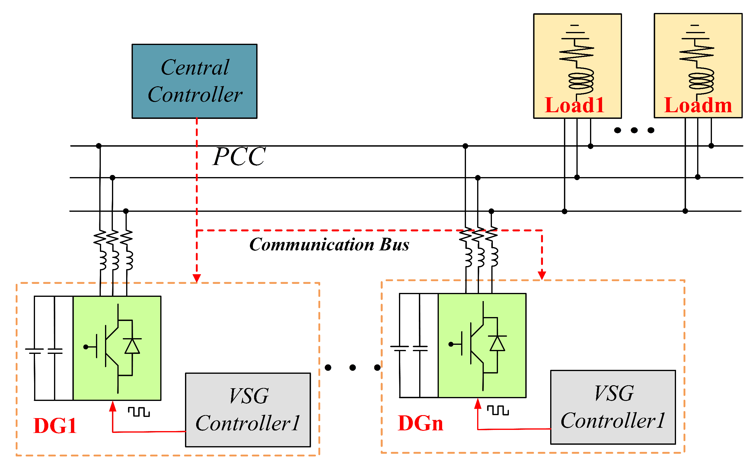
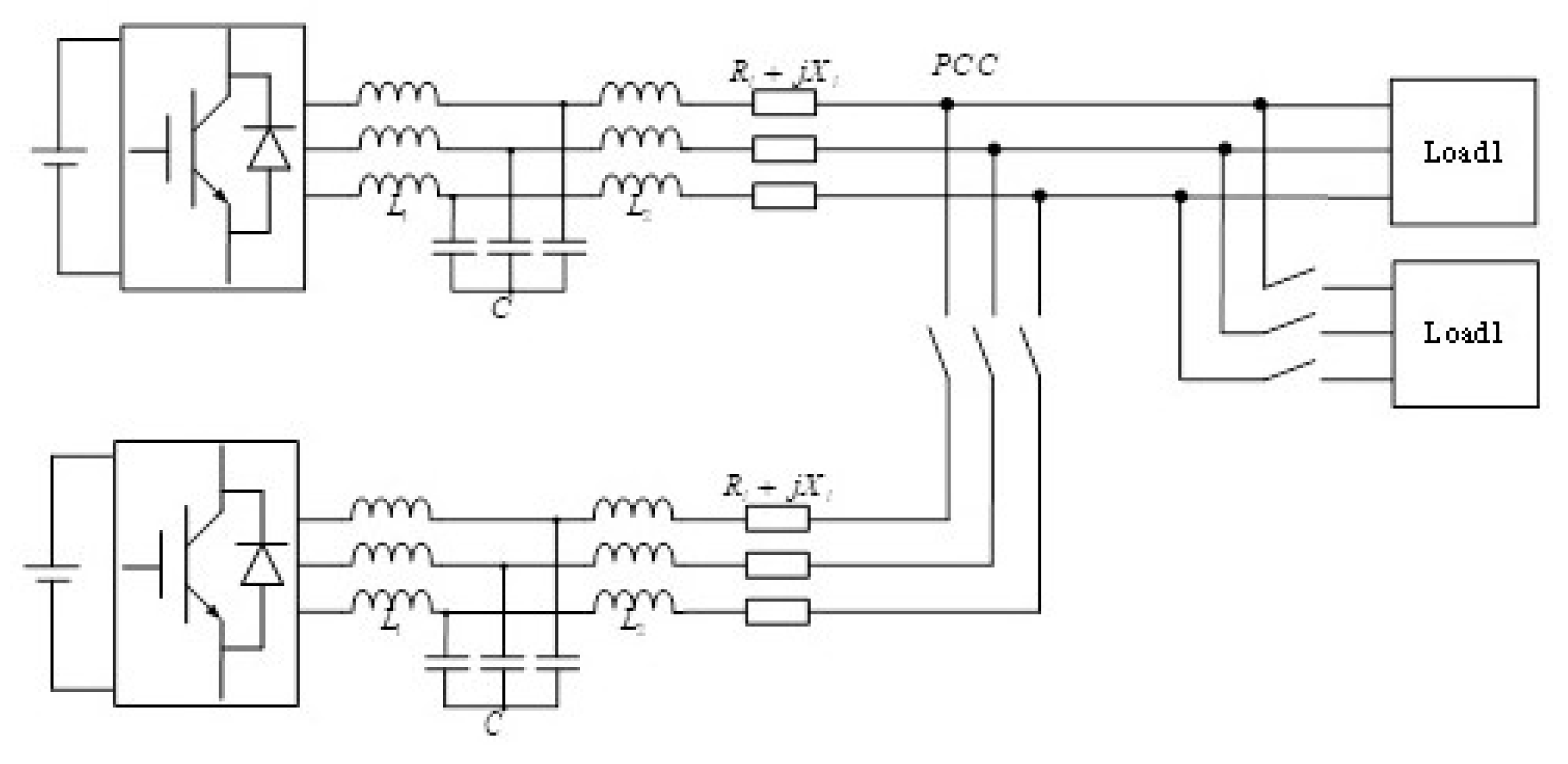
The islanded microgrid configuration discussed in this paper is shown in
Figure 1.
In order to implement the VSG control method that is proposed in this paper, some conditions and hypotheses about the microgrids need to be made. The voltage class of three-phase common bus in this microgrid is 380 V, and each DG unit is connected to the common bus through a feeder, whose impedance is acquirable and is supposed to be , where i refers to the ith DG. For the simplicity of the output power programme for DGs, all of the loads in the microgrid are lumped together as one; that means the local loads of each DG are not taken into consideration.
A central controller (CC) is equipped at the PCC; it is works for optimal power scheduling and can dispense reference active and reactive power for each DG. The voltage and current signals of the PCC bus are collected and sent to the CC, and the operation conditions of each DG are also sent to the CC through a low bandwidth communication bus. What should be illustrated is that the communication is only needed between the CC and DG units; the operating status of each load does not need to be sent to the CC. What is more, as a low voltage grid, the feeder resistance of the MG cannot be neglected, and the impedance of each feeder can be calculated by feeder specification parameters and distance.
3. VSG Equivalent Mechanical Characteristics Illustration
The inertia support of VSGs and their frequency stability will be analyzed in this part. Droop control is a conventional method for islanded mode microgrids. However, as analyzed in [
5], when comparing with VSG control, the droop control has a poor performance in both frequency response and small signal oscillation rejection. The droop control always suffers step frequency-change when it is disturbed by a small signal, whereas the frequency in VSG control can change slowly. That is because the VSG control model has a virtual inertia link in the equivalent swing equation, while the droop control has no inertia. As compared in [
22], the physical mechanism and characteristic parameters of SG and VSG share great correlations. In this part, the correspondence of an SG rotor and a VSG DC-side capacitor is analyzed, and a simpler equivalent method of capacitor voltage
and rotor angular speed
is proposed.
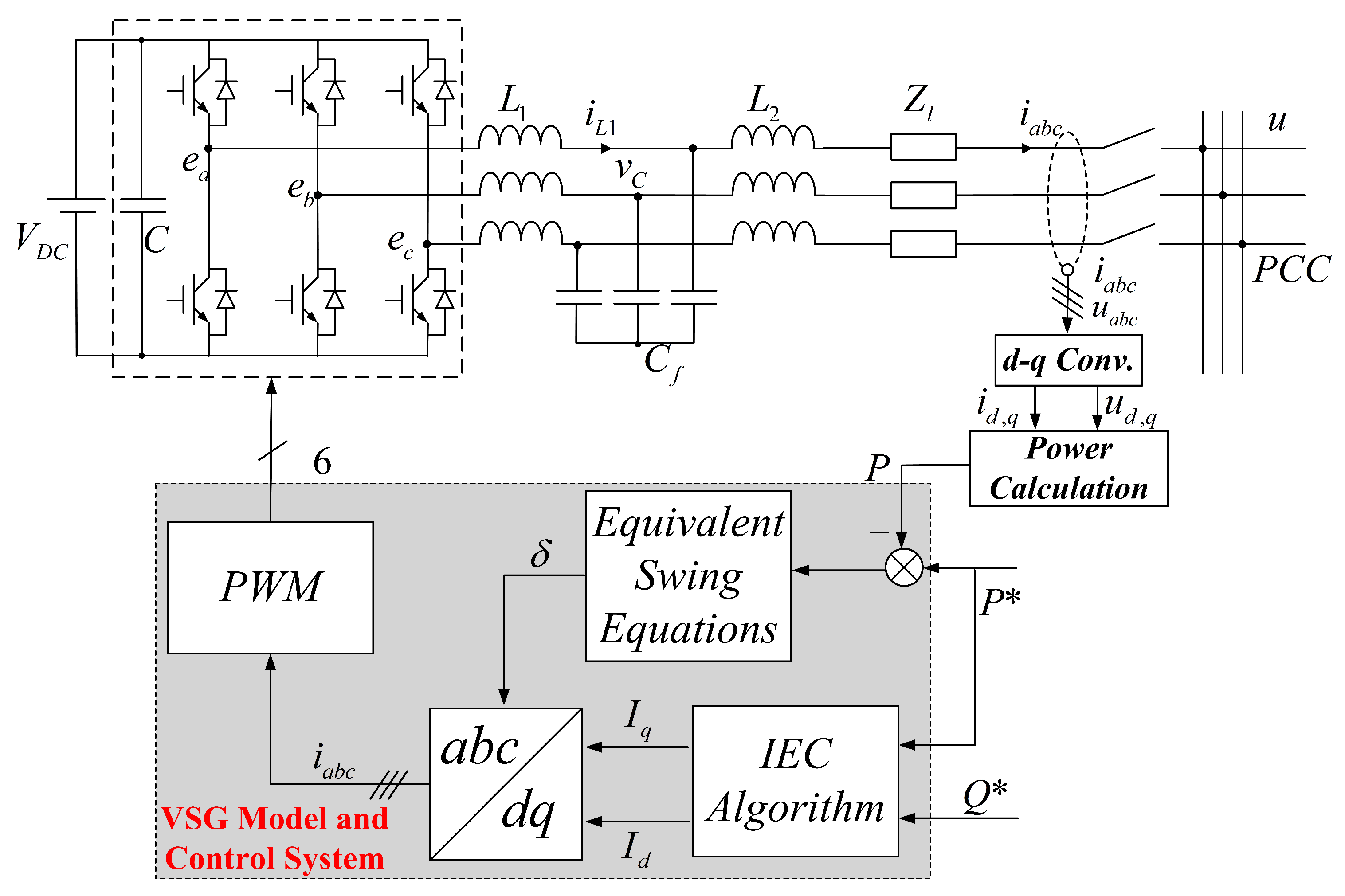
The three-phase inverter configuration with a VSG based control diagram is shown in
Figure 2. The three phase inverter legs operate under pulse width a modulation (PWM) command, which is determined by a VSG control loop.
is the terminal electromotive force (EMF) of the VSG, and is equivalent to the field EMF in SG; the voltage
after the LCL filter is the output voltage of the inverter, while
is the line current.
is the impedance of the transmission line between the inverter and the PCC. Proper control methodologies (like MPPT for photovoltaic and the wind turbine) are able to maintain DC voltage stability of each DG, and will not be discussed in this paper.
The DC-side capacitor of VSG and the rotor of SG have similar characteristics in energy transmission and dynamic character. For energy transmission, the SG transforms the mechanical energy of a prime motor to electrical energy through the rotor, which stores the kinetic energy in synchronous rotation; a similar energy transfer process of VSGs is realized by the charging and discharging process of a DC capacitor. The stored kinetic energy of an SG rotor at the synchronous angular speed
and the stored electrical energy of a VSG capacitor
are expressed as Equations (
1) and (2), respectively:
where
J is the rotor’s moment of inertia in SG and
is the synchronous mechanical angular velocity (rad/s) of the SG rotor. Assume that the number of pole-pair of the SG rotor is one, and there is one pair of poles on each phase of the stator. So that
equals the electrical angular velocity
.
C is the capacitance of the capacitor, and
is the rated voltage of it.
For synchronous generators, the mechanical part of the machine is governed by:
where
is the mechanical torque,
is the SG electromagnetic torque and
D is the damping coefficient.
For the rotor, the angular velocity and the rotating angle meet:
Multiplying
on both sides of Equation (
3), and taking
as the inertia time constant of SG,
is the rated mechanical power of SG; the rotor kinematic equation, which is also called the Swing equation, can be derived as:
where
and
are the mechanical power and electromagnetic power, respectively. The damping power
, which is proportional to electrical angular velocity
, is generated by damping winding. The main functions of damping winding are damping the system disturbances and eliminating the synchronous rotation speed difference of the SG rotor. The mechanical and electromagnetic torques meet:
Equations (
5) and (
6) describe the mechanical characteristics of SG, while similar characteristics also exist in the VSG. For the DC-side capacitor in
Figure 2, the capacitor current meets:
where
,
and
are the capacitor current, DC input current and DC output current, respectively.
is the chopper circuit current, which is utilized to restrict the DC voltage to a given region. Therefore, the chopper in the VSG is equivalent to damping winding in the SG. Comparing Equations (
6) and (
7), it can be learnt that
in the SG and capacitor current
in the VSG, and
in the SG and
in the VSG are counterparts, respectively, because each pair of them share the same dynamic character.
We define the equivalent inertia time constant of the VSG as:
(
7) can be rewritten as:
where
is the rated DC power,
is the inverter output power and
is the power consumed on discharge resistance
. The chopper circuit is activated when
exceeds the pre-defined bounds.
represents the per unit value of a specific variable. Therefore, the VSG equivalent swing equation can be constructed as:
Under the circumstance of DC voltage variation, the standard dynamical equation of the VSG capacitor can be obtained by linearizing
:
where
is an equivalent damping coefficient, which adds inertia to a system.
What should be noticed is that
cannot be equivalent to
directly, to compromise this, we multiply a coefficient to
:
Therefore, the following holds:
Therefore, Equations (
10) and (
13) together build the equivalent swing equation of VSGs.
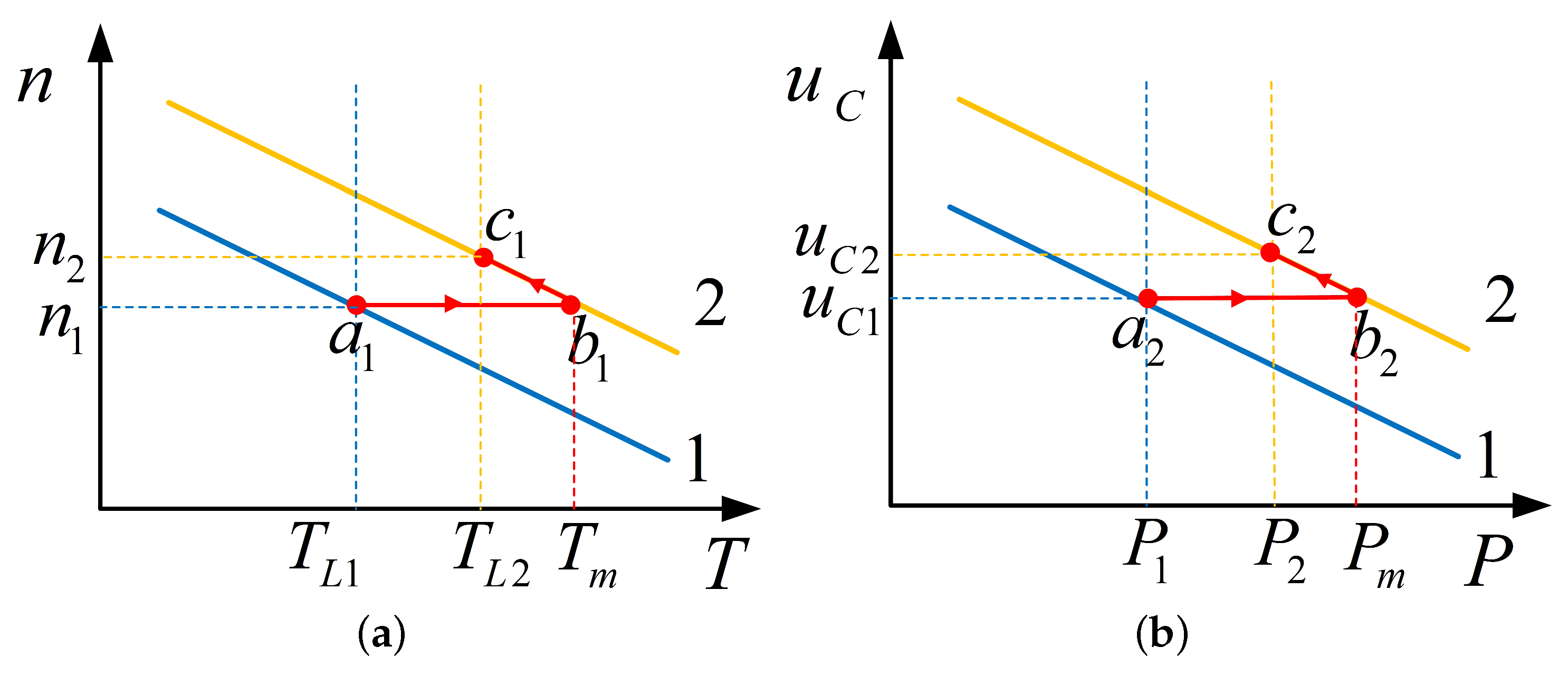
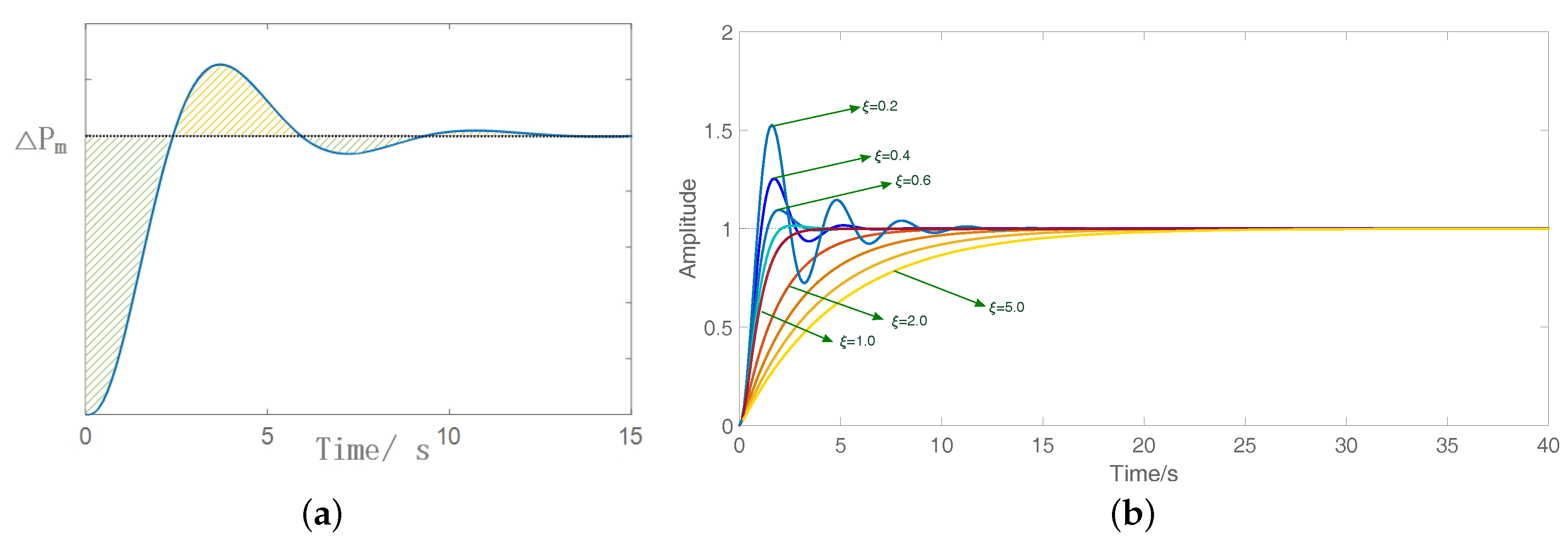
The equivalent mathematical model of an inverter’s DC-side capacitor is constructed to provide inertia and energy support to a VSG system. The process of operating status adjustment of a SG and VSG are shown in
Figure 3a,b, respectively. The mechanical characteristic curve of an SG can be approximated to a droop line of rotational speed and mechanical torque. Firstly, assume that, at the very beginning, the SG is operating at the static stable point
with the load torque
, while at time
t there is a drastic load variation from
to
, which triggers a power rescheduling; thus, the SG starts to operate along the new mechanical characteristic curve 2. Due to the effect of inertia, the rotational speed of the rotor cannot change instantaneously. Thereby, the operating status of the SG would jump to point
b at time
t and then increase its rotation speed along line 2. The transient process would not stop until the SG comes to another static stable point
. Similar transient process would occurs in VSG with the capacitor at DC-side works as energy storage devices. When the load of the DG changes, the appropriate adjustment of the operation status is made. Since the step change cannot be made to capacitor voltage, the energy of the inverter would not be released or increased instantaneously; therefore, the strike to the system can be relieved effectively.
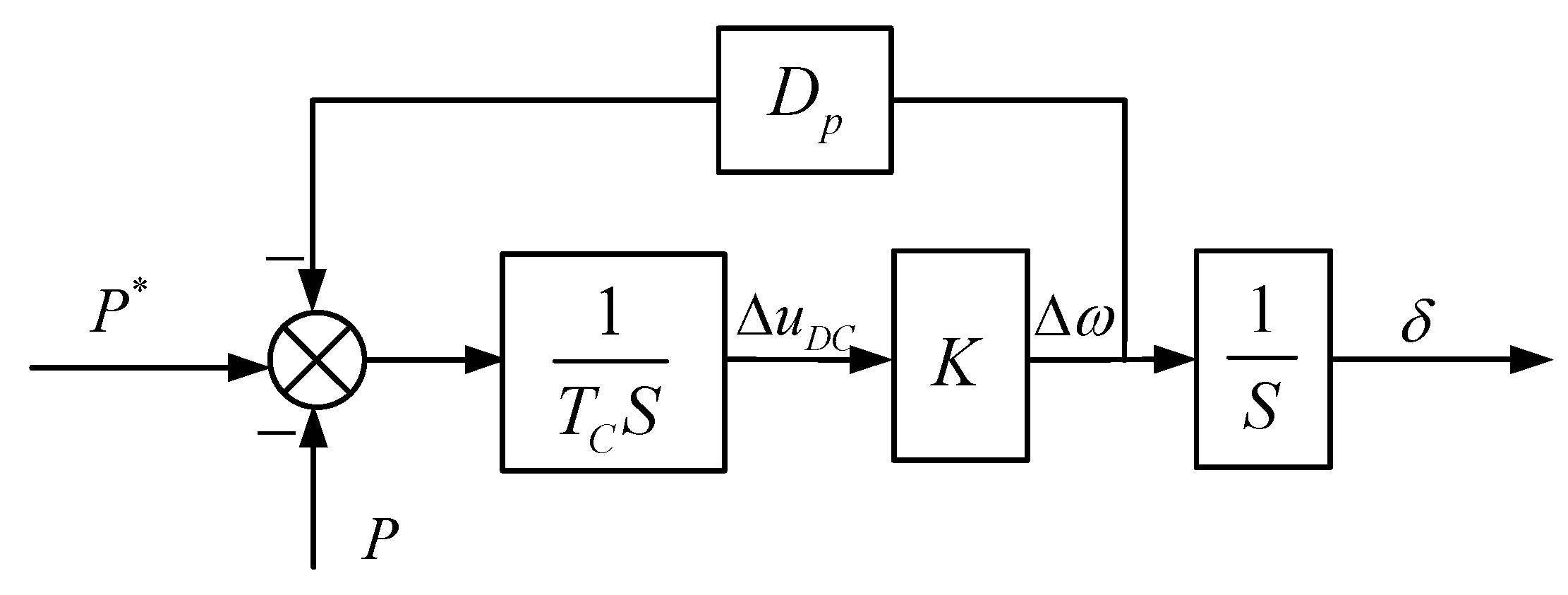
The dynamic model that is constructed in Equations (
10) and (
12) is shown in
Figure 4.
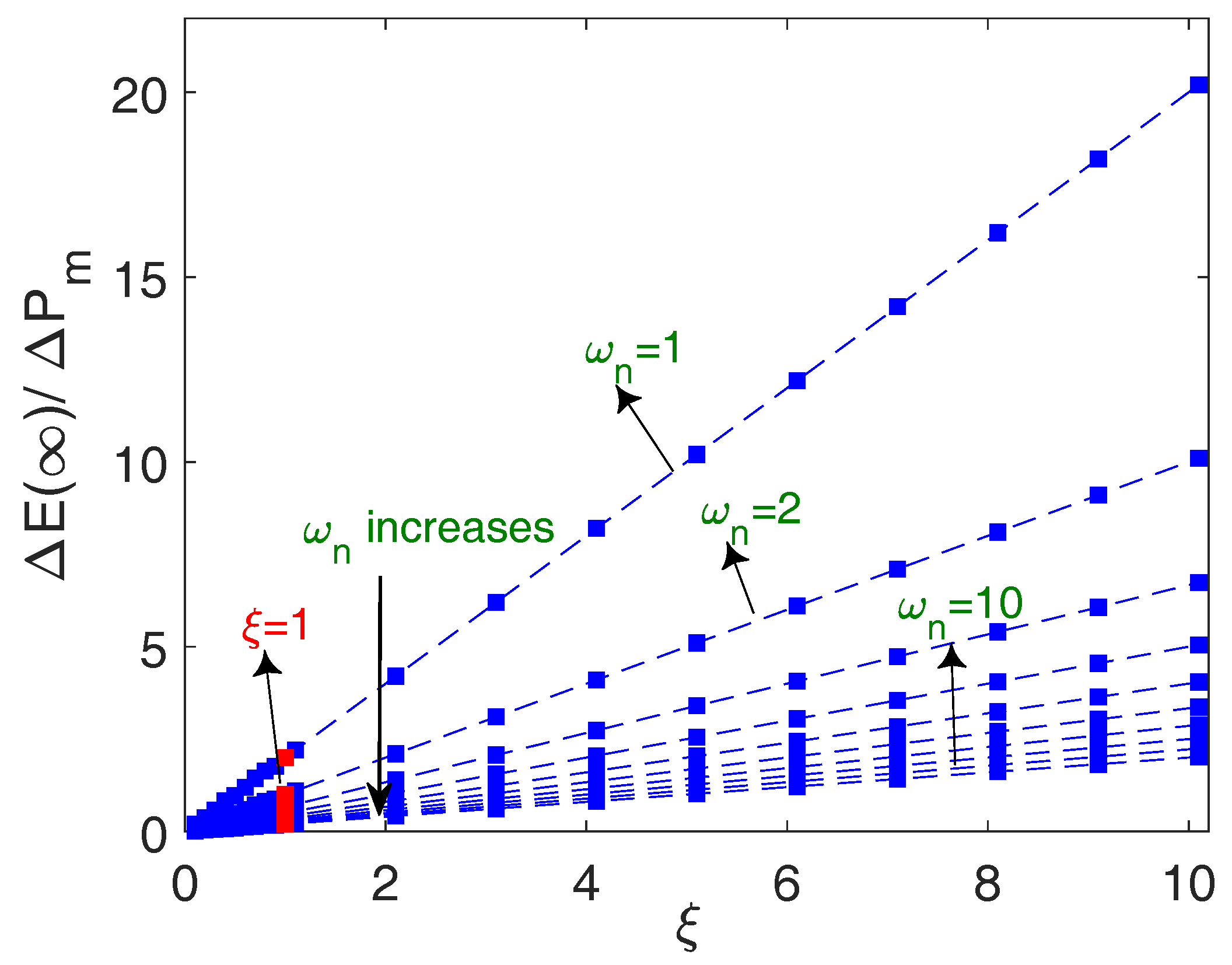
This model is a second-order system, and under the control of this system the frequency can be stabilized in finite time. The specific active power-frequency stability and energy issues of the DC-side capacitor will be analyzed in
Section 5.1 and
Section 5.2, respectively.
4. IEC Method for Voltage Stabilization and Accurate Reactive Power Tracking
In this section, a comprehensive equivalent strategy for stabilizing VSG voltage and achieving accurate reactive power tracking is proposed. The capacitor on the DC side of the inverter plays a critical role in the dynamic stability of the VSG. This DC capacitor is equivalent to the SG rotor, thus the equivalent swing equations that relate to the the frequency stability are derived from its dynamical characteristics. Moreover, later it will be proved that, when considering the R/X ratio of transmission line, both the active and reactive power will contribute to the VSG terminal voltage. Thus a comprehensive control strategy is proposed in this section, which is an imitation of the SG’s excitation control. The output active and reactive power of each DG will accurately track the set values, which are given by the central controller. Meanwhile, the PCC voltage can always remain at the rated value. Since the variation of load demands and the fluctuation of distributed generating resources happens frequently, it is necessary for DG units to adjust their output power to stabilize the PCC voltage of the islanded MG. In this part the imitation excitation control (IEC) method is first proposed, which focuses on outputting specific VSG power and maintaining the PCC voltage U constant.
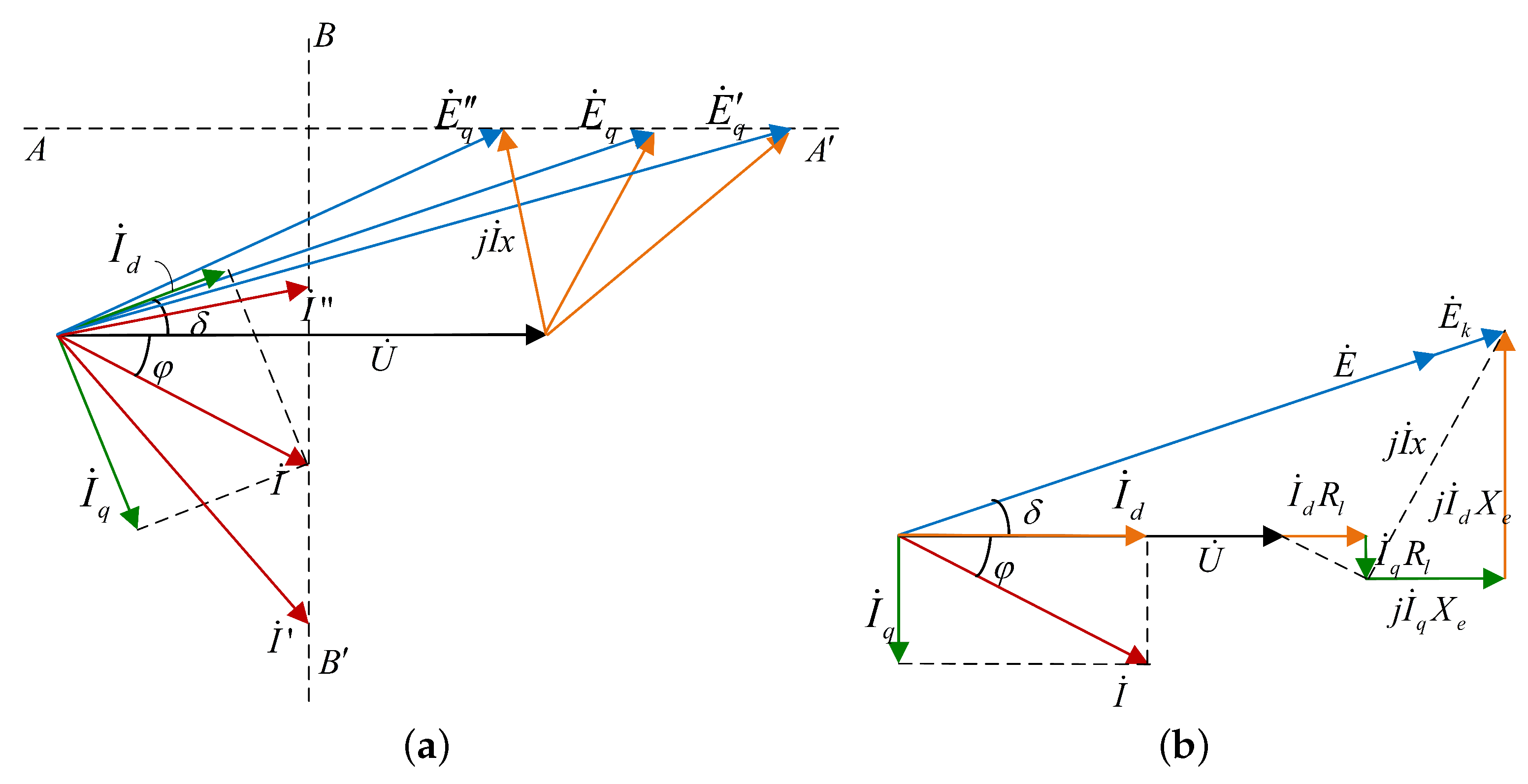
First of all, the equivalence of the VSG in series with the LCL filter and the SG is proven. For the conventional SG, since the output active power is immune to the value of the field current, it is feasible to adjust the reactive power with excitation control while keeping the active power constant; that is:
The equivalent phasor diagram of the excitation control for shaded-pole SGs is shown in
Figure 5a, from which it can be learnt that, with the variation of the field current, the induced electromotive force
of the SG changes along the line
, and the output current value
changes along the line
. Therefore, the variation of the field current can only adjust the reactive power and power angle
.
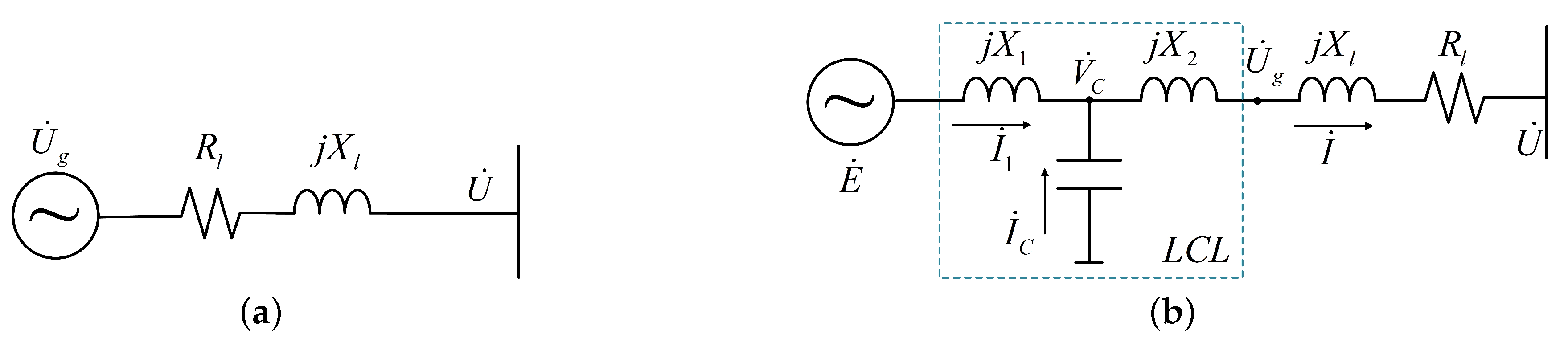
For the VSG, whose equivalent output circuit is shown as
Figure 6a, and the equivalent circuit of LCL filter (single phase) at its output ports is shown as
Figure 6b. As demonstrated in [
22], the VSG with L- and LCL-type filters corresponds to the shaded-pole and salient-pole SG, respectively. Therefore, the reactive power of a VSG can be controlled independently, like SGs. However, for the VSG with a low voltage feeder, whose R/X ratio usually is non-negligible, coupling between the active and reactive power makes this control scheme unrealizable. A proper method should be adopted to address this problem. In this part the imitation of the excitation control method will be proposed for the power sharing and voltage stable control of VSGs with non-negligible feeder resistance.
For the proposed method in this paper, the LCL filter is utilized. Moreover, together with the feeder impedance, it is equivalent to the stator of the SG, where the total impedance of the filter and line impedance corresponds to the armature reactance of the SG. As is shown in
Figure 6b, the phaser relation of currents and voltages of the equivalent stator yields:
It can be derived from the above equations that,
and
meet:
where
,
. Thus, the following can be derived:
Taking the d-axis alignments to
, the phasor diagram of the equivalent stator in the VSG is shown in
Figure 5b. It would simplify the calculation process, and its vector relations are equivalent to that in
Figure 5a. According to
Figure 5b, the VSG terminal EMF, output voltage and current meet:
where
. Moreover, taking the norm of the equivalent total impedance as
. Therefore, the active and reactive power without modulation are expressed as:
From Equation (
23), it can be learnt that, for the existence of line resistance, the active and reactive powers couple with each other, thus making them unable to adjust the reactive power independently. In consequence, a proper decoupling method should be utilized for the imitation excitation control (IEC) method. An orthogonal linear rotational transformation matrix
is used, which can transform active power
and reactive power
into ’modified’ powers
and
[
29]. Moreover, the good thing is that the information related to
and
are reserved completely.
where
,
. From
and
, the direct axis component and quadrature axis component of
can be acquired by:
To eliminate the system errors, the close-loop control system is constituted, which is shown as
Figure 2. In many studies, the VSG’s filter capacitor voltage, which is acquired by the PLL, is used as a feedback signal. Yet, for the voltage drop and power loss on the filter, it is unsuitable to use the capacitor voltage as the feedback signal to eliminate the EMF error. Fortunately, the information of the VSG output current is undistorted, thus the current-controlled inverter mode is used in this paper. According to the phasor diagram of the voltage and current in
Figure 5b and Equation (
21), the d-coordinate and q-coordinate components of current
,
can be calculated by:
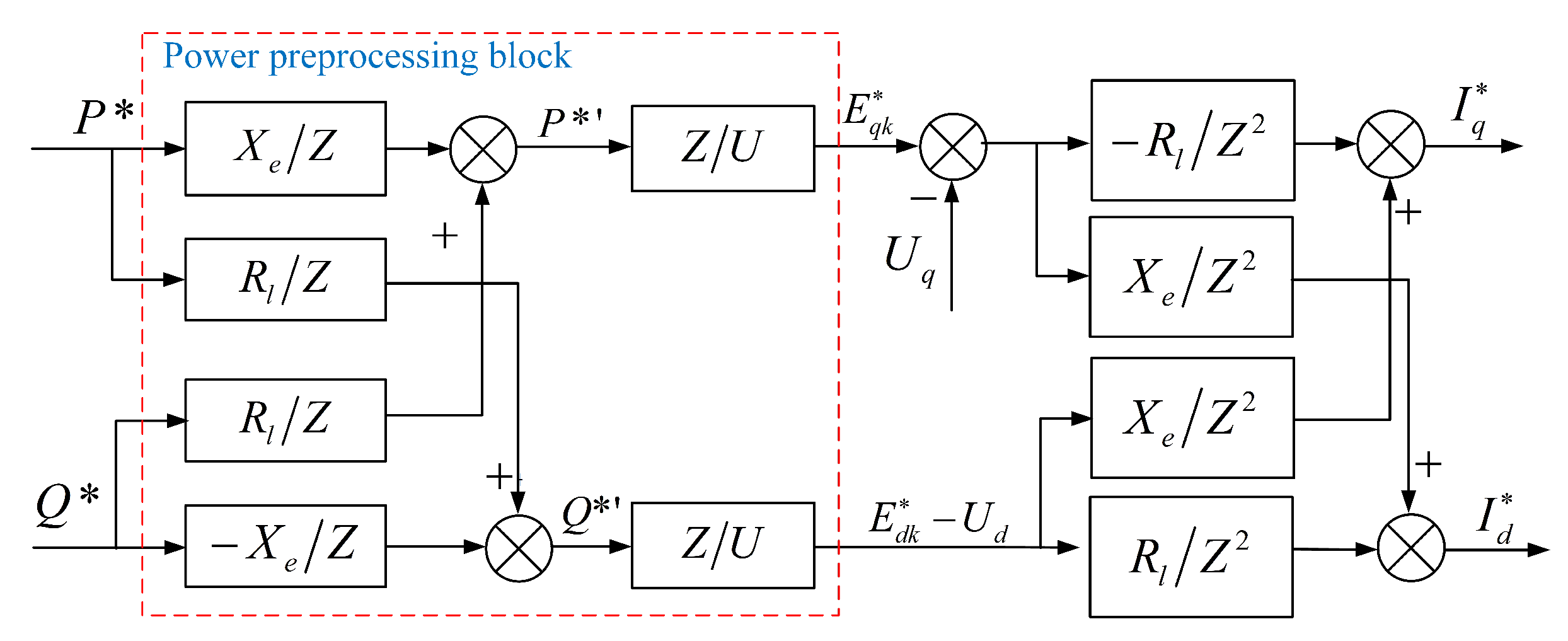
The block diagram of the equivalent power model of the VSG is shown in
Figure 7. It can be seen from Equation (
27) and
Figure 7 that both the control loops of the d-axis and q-axis have paths that cross the equivalent reactance
, which leads to coupling between active and reactive currents. Moreover, it may also cause a phase lag in the system transfer function, thereby causing instability in the system. To solve these problems, a feedforward decoupling method is utilized, in which a decoupling matrix
D is designed and meets:
Taking
, the unknown parameters are obtained as
,
, and the decoupled incidence matrix
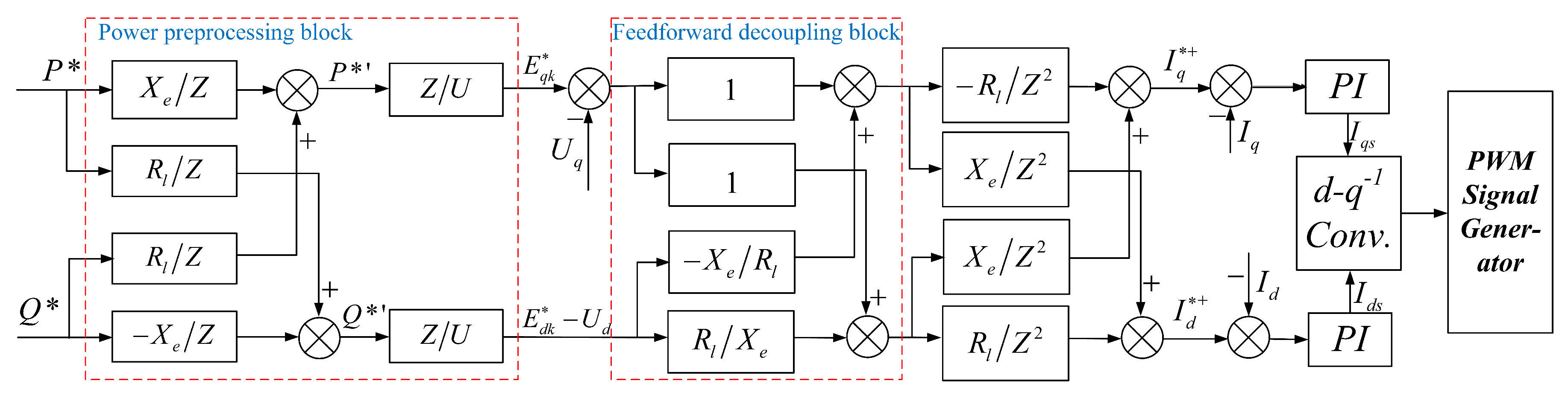
is converted to a diagonal matrix. The active and reactive power of the VSG that are under the control of the proposed IEC method are:
Equation (
28) shows that, under the control of the IEC method proposed in this paper, the active and reactive powers of the VSG that takes line resistance into consideration are equivalent to that of the conventional SG in form. However, the of VSG power leading the SG power for 90 electrical degrees due to the effect of the rotational transformation matrix
. Therefore, it is evident that VSGs with the line resistance correspond to SGs. The IEC control diagram with inverter output current feedback is shown in
Figure 8, in which the parameters with ∗ represent their reference value.
6. Case Study and Discussion
6.1. System Configuration and Parameters
To verify the validity of the proposed novel control method for VSGs in this paper, simulations are carried out in MATLAB/Simulink. The simulations are based on the microgrid configuration in
Figure 11, which operates in islanded mode. There are two inverters in a microgrid; they are connect in parallel, and are connected to the PCC with their feeders. For each inverter device, a super-capacitor is installed for energy adjustment and inertia support. Besides, there are two load groups in MG as a form of common load; thus, the two VSG units share the load. The detailed system parameters and control parameters of the proposed VSG control method are shown in
Table 1.
For the traditional droop control method, the influence of filters and resistances on feeders and the couplings between active and reactive power are omitted. Other physical parameters of inverters are the same as those in the proposed VSG method. Besides, the droop parameters of P-f and Q-V are and , respectively.
6.2. Time Domain Case Study
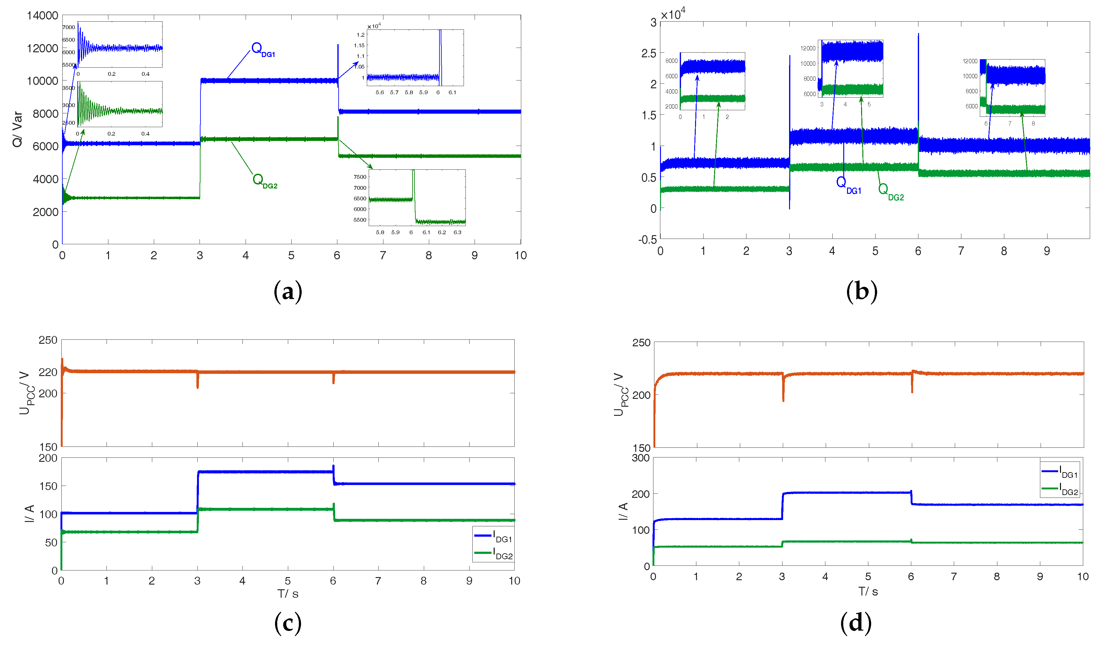
First of all, the time domain comparative simulations are conducted for the proposed IEC based VSG control method and the droop control method in the same scenarios: (1) The simulation starts at 0 s with the load capacity as kW, kVar. The power allocation is: kW, kVar for DG1, and kW, kVar for DG2. (2) At t = 3.0 s, there is a load increase to 175 kW, 16.5 kVar; accordingly, the power allocation for each DG is adjusted to: kW, kVar, and kW, kVar. (3) At t = 6.0 s, there are some loads quit from the microgrid, which makes the load demand decrease to 155 kW and 13.5 kVar. Thus the output of each DG should be adjusted in timely way: kW, kVar and kW, kVar.
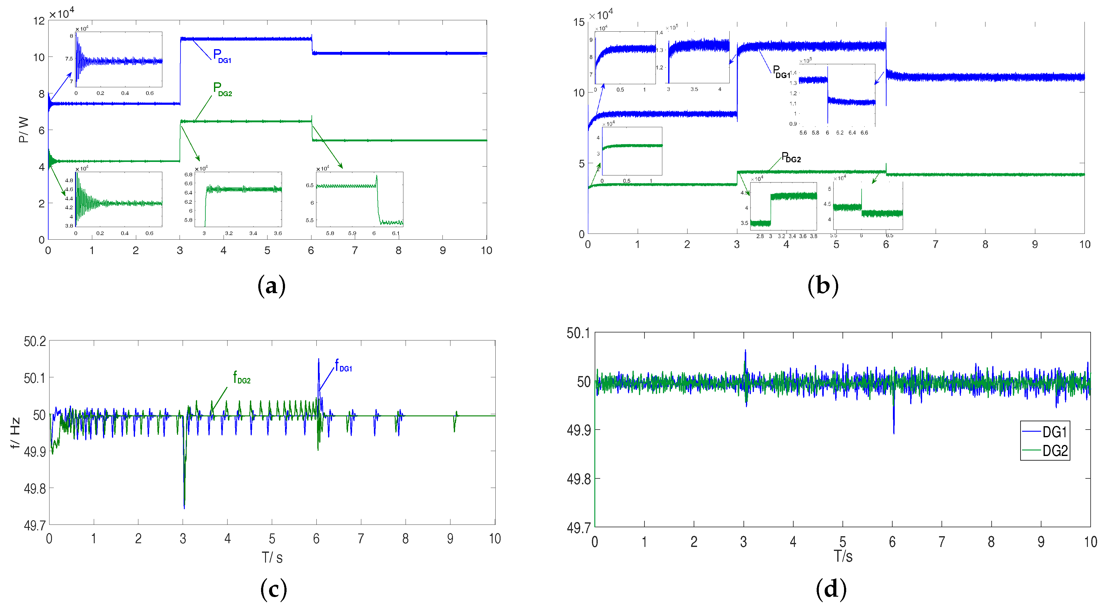
The simulation results are shown in
Figure 12 and
Figure 13. The specific simulation results analyses about the two methods are given as follows:
The active and reactive power responses of the two methods are shown in
Figure 12a,b and
Figure 13a,b. From which it can be learnt that the proposed method works better than the conventional droop control.
Firstly, for the proposed method, the two DGs can all accurately follow the set points of active and reactive power, with the power error under 5%. While the conventional droop control cannot output the specific power. For DG1, the steady state active power errors of droop control during the three periods are 13%, 20% and 11%, respectively; while the corresponding reactive power errors are 17%, 17% and 25%, respectively. Worse data is shown in DG2, with 22%, 32% and 23% active power negative offsets and 50%, 21% and 22% reactive power negative offsets.
Secondly, from
Figure 12a,b it can be learnt that, compared with the conventional droop control, the proposed method in this paper has faster response speed and shorter transient process time. Last but not least, the overshoots of output power under the proposed method are smaller than those of the droop control method during the transient process. The biggest overshoot of reactive power of droop control is even 1.3 times its rated value, while the overshoots of active and reactive power of the proposed method are within 10% and 20%, respectively. Moreover, it can be learnt from
Figure 12b and
Figure 13b that, under the droop control, there is still a large scale of power fluctuation span in the stable state, about 3% of the rated value.
Figure 12c,d illustrates the dynamic performance of frequency under the control of the two kinds of methods. From
Figure 12d, it can be learnt that the droop control has a better performance on the maximum frequency deviation, which is about 0.13 Hz, while the maximum frequency deviation of the proposed method is 0.26 Hz. That is because, in order to prevent the system breakdown, the P-f, Q-V droop coefficient must be set sufficiently small. The frequency performance in this paper, however, can also meet the demand of system stability. The steady state deviation can be maintained under 0.1% of the rated value, and the maximal deviation of the transient process is under 0.5% of the rated value. Furthermore, compared with the continuous random fluctuation in the droop control method, the fluctuation of frequency for the proposed method is smaller in degree. Moreover, approximative periodic fluctuation can be modified or even eliminated by adjusting the PI controller parameters or adding a resistance in the LCL filter.
The voltage Root Mean Square (RMS) value of PCC and output current RMS of the two DGs in the two methods are shown in
Figure 13c,d, respectively. It can be learnt that, although both the methods can realize the voltage stability of the PCC, the voltage and current of the proposed method outperform that of the droop control method, for the proposed method has faster system response velocity and shorter transient time. What is more, when there are operation modes switching in the system, the maximum voltage sag of the proposed method is much smaller than that under the droop control.
In conclusion, the proposed method is valid for the operation of a microgrid with drastic power variation. Moreover, it outperforms the conventional droop control.
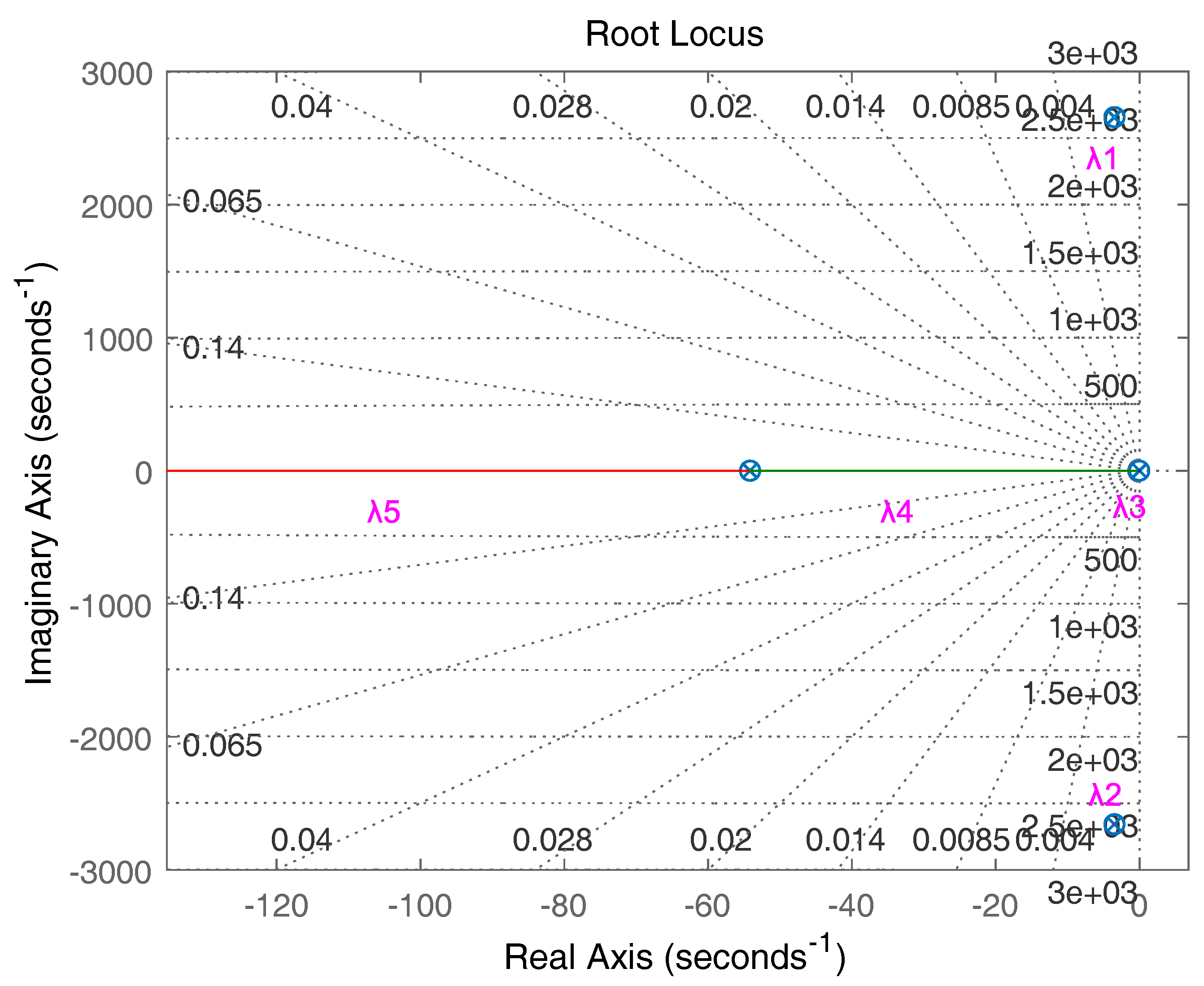
6.3. Small Signal Stability Verification
The static stability of the system under the proposed method is verified by the root loci diagram. The small signal model of the system is constructed based on the method in
Section 5.1. Taking the parameter values from
Table 1, and setting the R/X variation range as 0.01 to 100, the characteristic root loci of C(s) with the variable parameters
K and R/X in each feeder are shown in
Figure 14,
Figure 15 and
Figure 16 respectively.
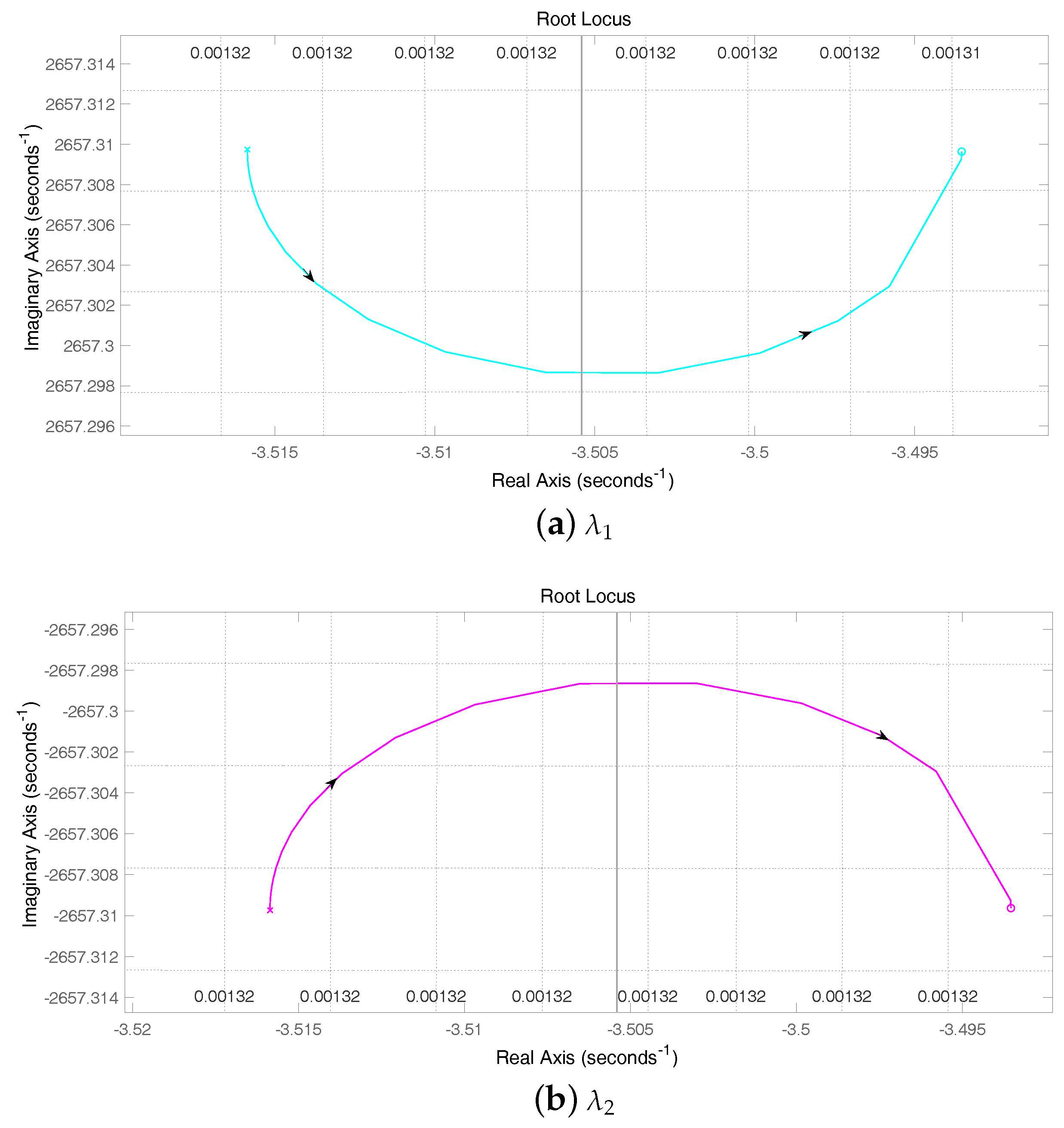
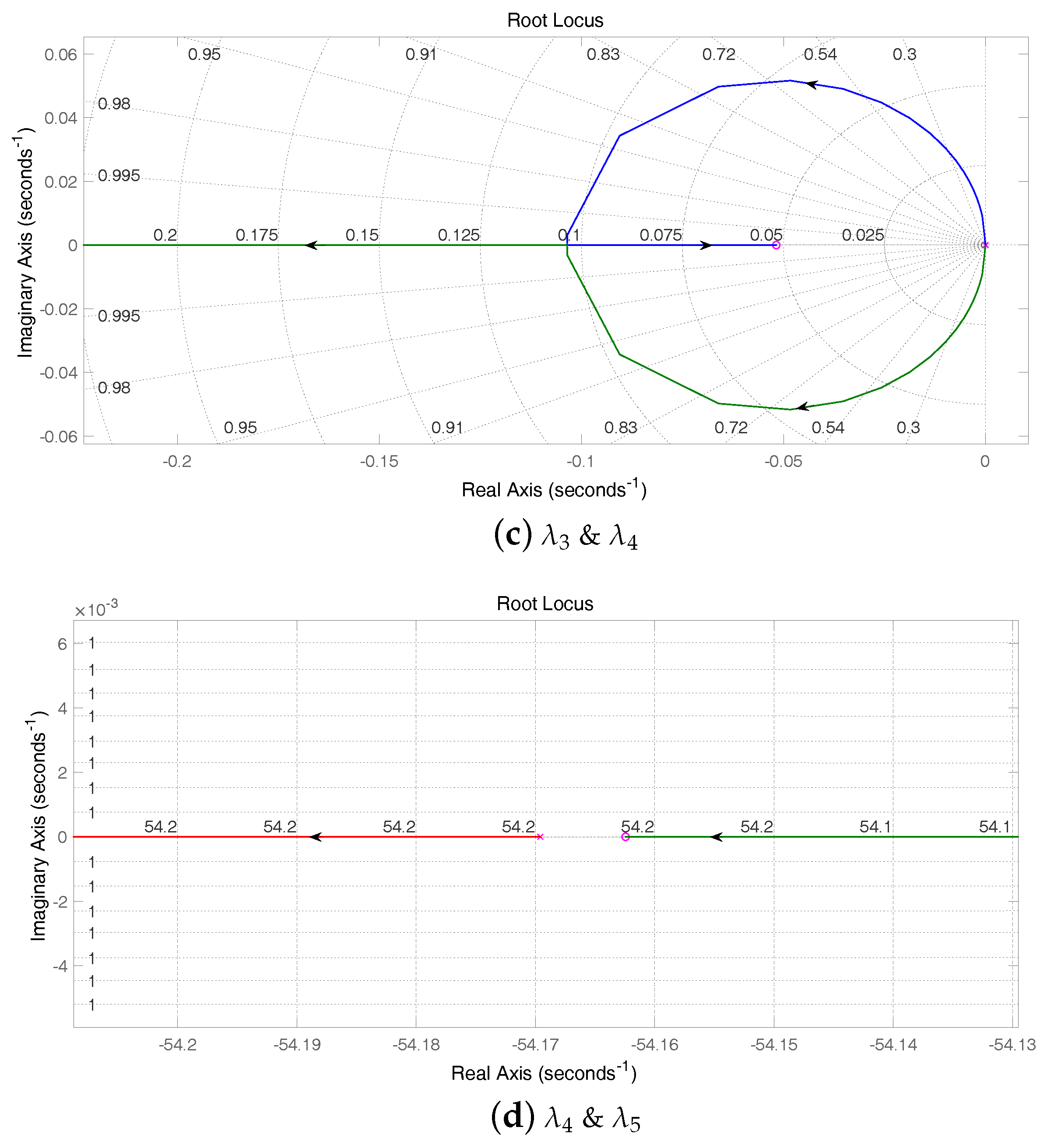
From the zoomed in diagram of root loci in
Figure 15a–d, it can be learnt that, under the control strategy proposed in this paper, the small signal model of VSG output power is statically stable, for its roots always relay in the negative plane.
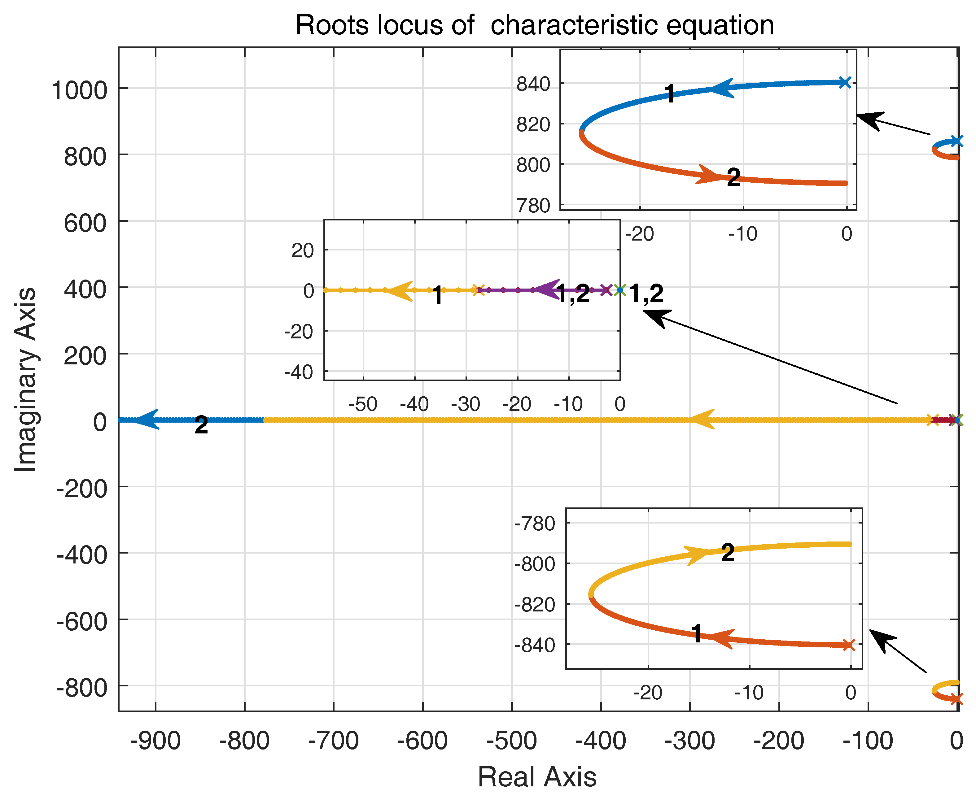
Figure 16 shows the variation tendency of characteristic roots while the R/X changes from 0.01 to 100. Since, with the changing of R/X, there are nonlinear variations of parameters, it is difficult to plot the root locus directly. Therefore, the R/X variation range is set as 0.01–100, and we believe that this range could involve most of the R/X cases of feeders’ impedance in real MGs. From the zoomed in views of
Figure 16, it can be learnt that, with the changing of R/X, the small signal model of VSG power is also stable, whereas with the increasing of R/X, the system is unstable; that is, the increasing of line resistance does influence the stability of DG power, so, to some extent, it proves reasonable for taking the influence of line resistance into consideration.


