1. Introduction
In recent years, with the rapid development of the economy and the advancement of urbanization, China’s bridge construction has reached its crescendo. Bridges play an important role in the transportation system by supporting economic and social development and are therefore regarded as one of the most important and indispensable infrastructures. According to the statistics, there are currently more than 800,000 road bridges in China, ranking first in the world [
1], which gives severe pressure to their maintenance. However, at the present stage in China, people still mainly focus on construction but not maintenance. During the long-time operation of the bridges, bridge structures suffer different levels of damages caused by loads and environmental effects, which then reduces the structures’ reliability and shortens their expected service life-time. For example, severe rust and breakage of the boom can result in bridge collapse, such as the destruction of the Yi Bin south gate bridge in China. There are also many similar cases of bridge defect or even destruction accidents, and the main cause is the lack of maintenance [
2,
3].
Bridge management system (BMS) is an integrated computer system to provide decision support throughout design, construction, operation, and maintenance phases. BMS can improve the efficiency of management and decrease redundant costs in dealing with infrastructure management issues [
4]. Many countries invested a great deal of resources and efforts to develop efficient BMSs, including Finland [
5], Denmark [
6], Germany [
7], and Japan [
8]. In China, Chinese Bridge Management System (CMBS) was developed by the Ministry of Transport of China (MOT) in 1993 and has been widely used in China after continuous improvement. The main functions of CBMS are to master the basic data of highway bridges, supervise the regular inspection, and provide technical support for maintenance [
9]. However, there are still many problems during the application of CBMS. Firstly, the information stored in the system is fragmented and isolated. Secondly, it is hard to realize visualization when the maintenance information is separated from the bridge model and makes it difficult to handle for users. Additionally, bridge engineers and managers find it difficult to collaborate with each other through the system.
In recent years, building information modeling (BIM) has become the most flourishing technology in the building industry, and it has been extended to infrastructure engineering [
10]. This technology is a new approach and can be used for design, construction, and facilities management of structures, wherein a digital representation of the building process is used to facilitate the exchange and the interoperability of information [
11]. The application of BIM brings about cost reduction, quality control, and efficiency improvement throughout the life cycle of the project. A survey by Stanford University in the United States pointed out that BIM can eliminate 40% of extra changes, reduce the contract price by 10% by discovering and resolving conflicts, and shorten the project duration by 7% [
12]. With these advantages, BIM has also been adopted by commercial software, such as Autodesk Revit, ArchiCAD, and Allplan [
13]. Furthermore, BIM has been successfully implemented in many bridges’ designs [
14,
15] and constructions [
16,
17,
18]. However, the application in the maintenance phase started relatively late. McGuire and Atadero [
19] utilized the BIM to manage the inspection and evaluate information. Abudayyeh and Al-Battaineh [
20] adopted the as-built bridge information model for maintenance and management. Some scholars [
21,
22,
23] also combined the BIM with the traditional management system to improve maintenance efficiency.
In China, however, the lifecycle bridge management system based on the BIM technology is still under development. This paper introduces the development of a BIM-based BMS, which integrates the geographic information system (GIS), develops the necessary Industry Foundation Classes (IFC) and International Framework for Dictionaries (IFD) standards, which are still in blank in China, implements the Web-BIM oriented management, and realizes the collaborative work among all related users. This BIM-based bridge management system is supposed to improve the efficiency of maintenance management in order to satisfy the keen demand of maintenance management from substantive bridges in China.
2. System Goal and Requirement
With the huge inventory of Chinese bridges, maintenance of these bridges becomes especially important and challenging. An informationalized management system is helpful and necessary. Many BMS have been developed, and fairly good practical results have been achieved, such as GIS-based BMS [
24], visual inspection data-based BMS [
25], and consecutive condition assessments-based BMS [
26]. In this paper, we introduce a BIM-based BMS. The main target is to increase the management efficiency, make it visualized and easy to use, and provide a collaborative management platform for all people involved in the projects. To realize it, the bridge management system should:
(1) Integrate the BIM with the GIS. As a node of the transportation network, geographic information is crucial to the bridge. Moreover, our management is not only focused on a single bridge but the bridges at a certain transportation line or a certain area. Information of the group of the bridges helps to grasp the overall condition of the transportation and gives us guidance in maintenance.
(2) Realize the Web operable BIM system. Confining the users to computers is no longer welcome. The system should be operable at the Web, reducing the dependency on heavy BIM software, and, most importantly, making the portable device based operation possible.
(3) Have a unified database. The database of the system should support different kinds of data. Information should have the same coding rule so that all data can be searched, retrieved, and analyzed. Interaction between systems can also be implemented.
(4) Realize the function of structural inspection and monitoring. Condition of the bridges reveals the safety of the bridges. Structural inspection, health monitoring, as well as the performance evaluation are therefore the most important in the management system.
(5) Realize the collaborative management. By collaborating, all people with different jobs work together; collaborative management is a key issue to increase the efficiency of the management.
(6) Achieve the multi-scale visualization during the management. Visualization is a significant advantage of the BIM-based management system. It makes the system easy to understand and easy to grasp for people.
As a popular informationalized method, the term BIM itself has several definitions, such as a product, a collaborative process, and a facility life cycle management requirement [
27]. It can also be regarded as a combination of the concepts of building information modeling and building information management. Three-dimensional representation, information integration, and digital models are the three significant features of BIM. The collaborative management system utilizes the advantages of BIM to provide better service for bridge maintenance, which makes up for deficiencies of the traditional management system. Considering the merit of the BIM technology, a BIM-based bridge management system is developed in this paper to improve the maintenance efficiency and release the management pressure of large numbers of existing bridges.
3. Key Points of the Proposed Bridge Management System
3.1. BIM Standard Extension
As mentioned earlier, some relevant standards are still incomplete or blank in the bridge industry in China. The lack of uniform BIM standards has become one of the main obstacles to the application and the development of BIM [
28]. Compared with other industries, civil engineering projects usually include many stages—planning, design, and construction—and involve many participants. Different types of BIM software are adopted in the process. Without a unified BIM standard, it is hard to achieve information sharing among different stages and software, which leads to a large number of repetitive works. It is necessary to establish information storage and exchange standard. Otherwise, the values of BIM are not realized fully.
3.1.1. IFC Standard Extension
The IFC standard is an open international standard for the expression and the exchange of building product data, supporting data exchange, and sharing throughout the life of a building project. The architecture of the IFC standard consists of four levels; from the bottom to the top, these are resource layer, core layer, interoperability layer, and domain layer.
At present, the IFC standard is incomplete, and it is hard to cover the whole life-cycle information of a bridge [
29]. Thus, it is necessary to make an extension by using EXPRESS language based on the existing IFC framework. The bridge member, such as beam and abutment, can directly refer to IfcBuildingElement in the existing IFC framework. However, structural defect, inspection, and evaluation information should be defined by extending the attribute set.
Table 1 defines the attribute set of bridge defect information and reinforcement information.
Table 2 and
Table 3 list the specific attribute name and the type of the attribute set.
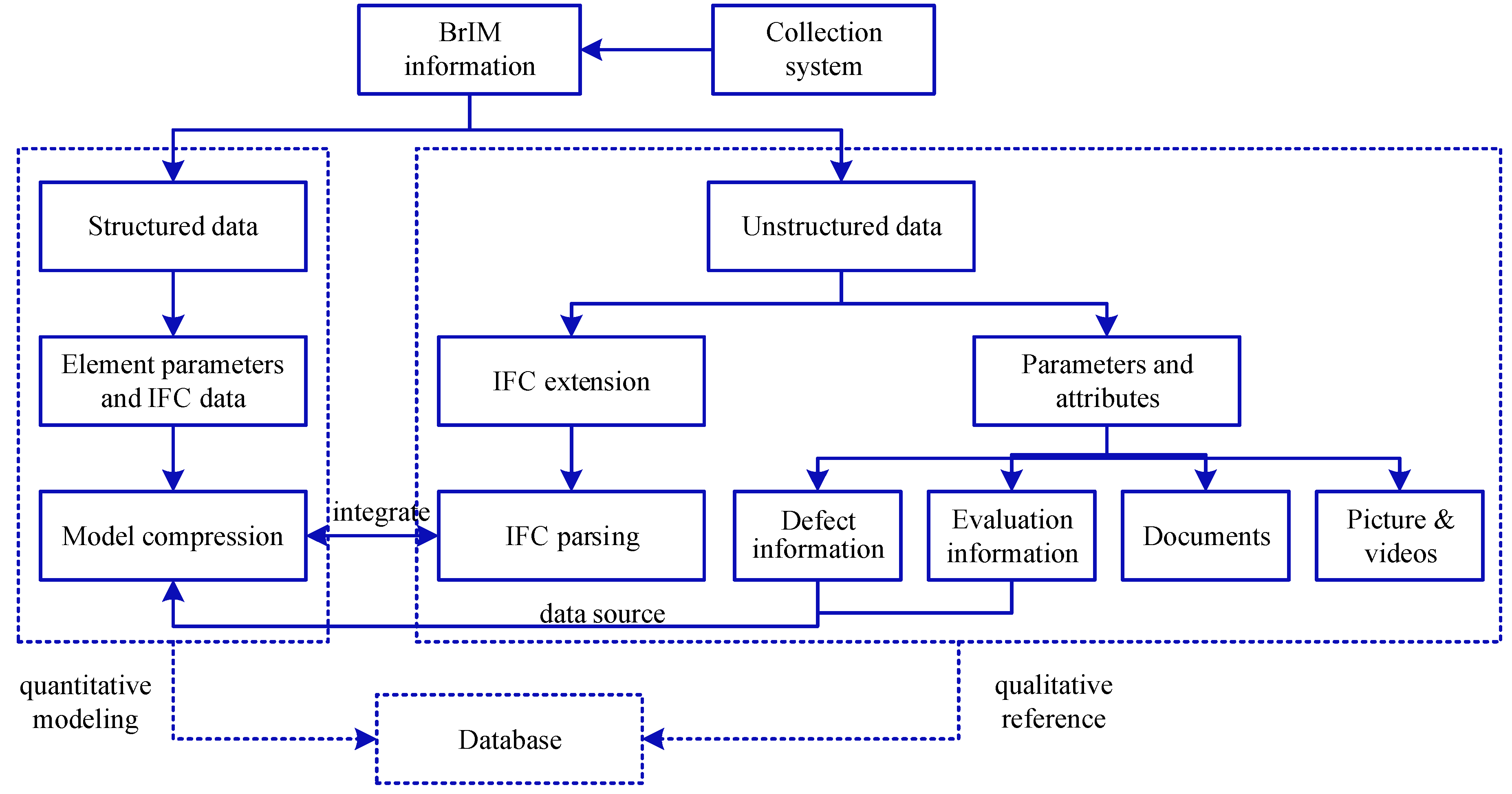
Table 4 lists the attribute definition of the concrete crack. Finally, the bridge maintenance information is attached to the bridge members through IFC relationship entity. In this way, the IFC framework targeting at bridge maintenance is built completely, which provides a uniform standard for information exchange and delivery. Bridge information models can be imported and exported by mainstream BIM software such as Autodesk, Bently, Dassault, etc. Since the unstructured data cannot be directly expressed in the existing IFC standard, it is necessary to extend to encoding the attribute information. Parameter and attribute information sets can be added to unstructured data, including disease information, assessment information, files, pictures, and videos. As shown in
Figure 1, the attribute information set combined with the structured information through data sources is compressed together and integrated with IFC parsing. Thus, the entity model of the IFC extension for bridge disease and evaluation is completed, and the structural defect extension rules are formed.
3.1.2. IFD Standard Extension
The descriptions of information are usually distinguished in different languages and under different situations, which makes information uncertain and inaccurate. The IFD defines a globally unique identifier for each conception. In China, IFD standards have been established in the field of architecture and railway industry [
30]. However, the IFD standards in the highway field are still blank in China. This paper proposes the IFD standard for Chinese high way industry and makes a supplement for the highway bridge maintenance.
International Standard Organization (ISO) provides the information classification framework (ISO 12006-2). This framework [
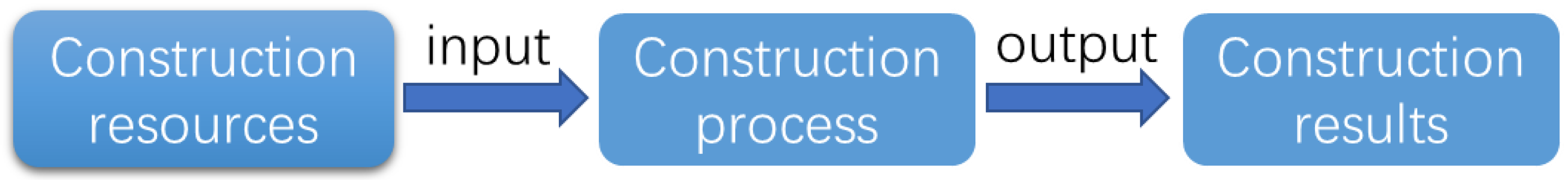
31] divides the building information into three categories: construction resources, construction processes, and construction results. Construction results are produced by applying construction resources to the construction process, as
Figure 2 shows. Among them, the primary construction resources include products, tools of production, roles of bridge engineers, roles of bridge engineering organizations, information, materials, attributes, etc. Meanwhile, the construction process includes the behavior of bridge engineering, the project phase of bridge engineering, the professional field, etc. The construction results consist of the structures classified by function, morphology, and so on. The classification and the encoding of the bridge maintenance information can refer to or extend from the existing IFD standards. For the cases where the current standards cannot satisfy the needs, information needs to be classified and encoded based on the ISO 12006-2 framework.
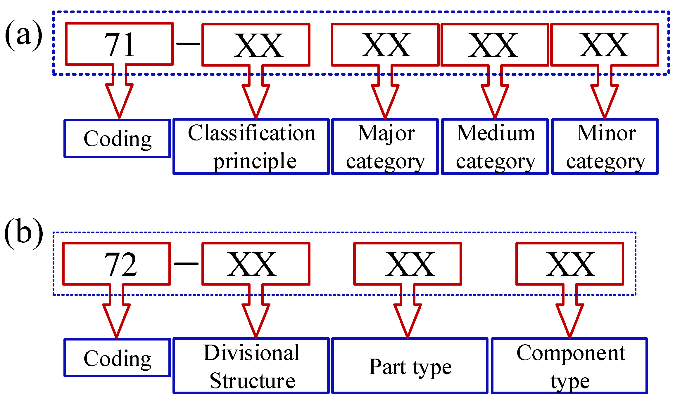
The numerical method is applied to encode the information. The coding consists of two parts: table name and coding of different levels (each two numbers represent one level), which are separated by a dividing line. A part of coding is to directly quote IFD standards in the field of construction, while another part is to extend the building standards. Coding should independently compile the information. Among them, codes with initial numbers 71, 72, 41, 74, and 78 indicate bridge type, bridge component, attribute, bridge behavior, and bridge characteristics, respectively. The coding principles of the bridge type and the bridge component are shown in
Figure 3. Because of the limitation of space,
Table 5 only lists a part of the engineering behavior information coding in the bridge maintenance phase.
Table 6 gives a part of the structural defect, evaluation, and reinforcement information coding of the bridge. Defect levels, associated maintenance, and repair priorities are defined as well.
3.2. Structural Modeling Method
In the bridge life-cycle planning, the information model is expected to be established during the design and the construction phases and then delivered to the maintenance phase. However, at present, most existing bridges did not apply the BIM technology in design and construction. Besides, some as-built information models make it hard to satisfy the needs of bridge maintenance due to the restriction of software. As a result, a bridge information model for maintenance needs to be rebuilt in most cases. This part introduces a structural modeling method by using Autodesk Inventor, taking the Grand Canal Bridge modeling process as an example. The background of Grand Canal Bridge is introduced later in
Section 5.
Autodesk Inventor is modeling software that has strong curve design capability, powerful assembly, and information integration functions, which gives it the ability to build the model of the Grand Canal Bridge. Since the workload of modeling is large, it is necessary to unify the basic information such as coordinate system, unit, and storage path before building the model. The specific modeling steps are as follows:
(1) Establish component models. The Grand Canal Bridge is divided by structural components such as bridge decks, abutments, pile foundations, etc., and each component is modeled separately by creating a “part” in the Autodesk Inventor. However, to build all the components one by one is inefficient. The software provides a parametric method, which can be used for building different types of components effectively.
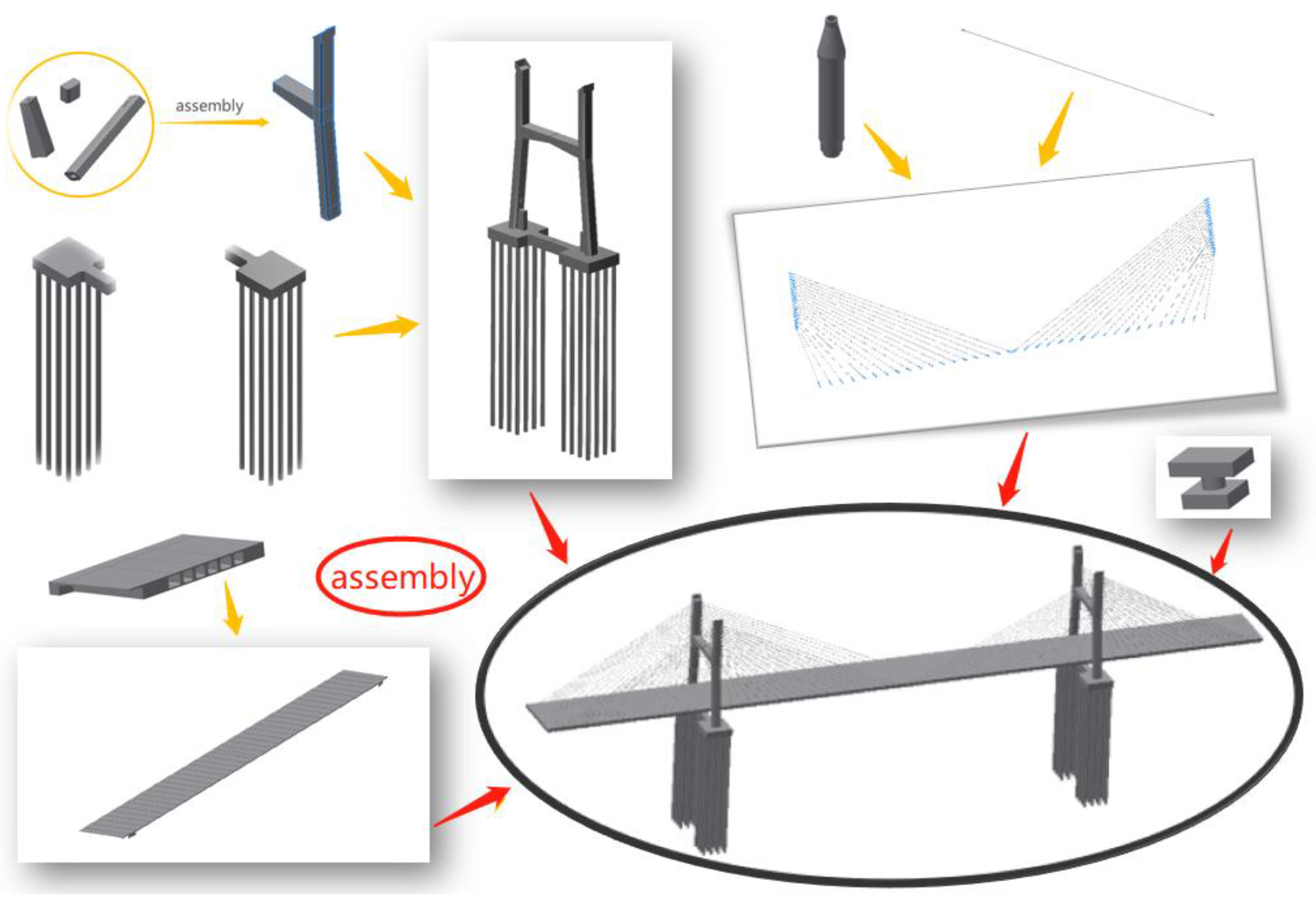
(2) Assembly of components. The separate components need to be assembled to form the bridge model. For components with geometric constraints, users can assemble them directly. For component types without direct constraint relationships, the reference surfaces and the reference points need to be created to help determine the location of the components. The assembly details can be seen in
Figure 4.
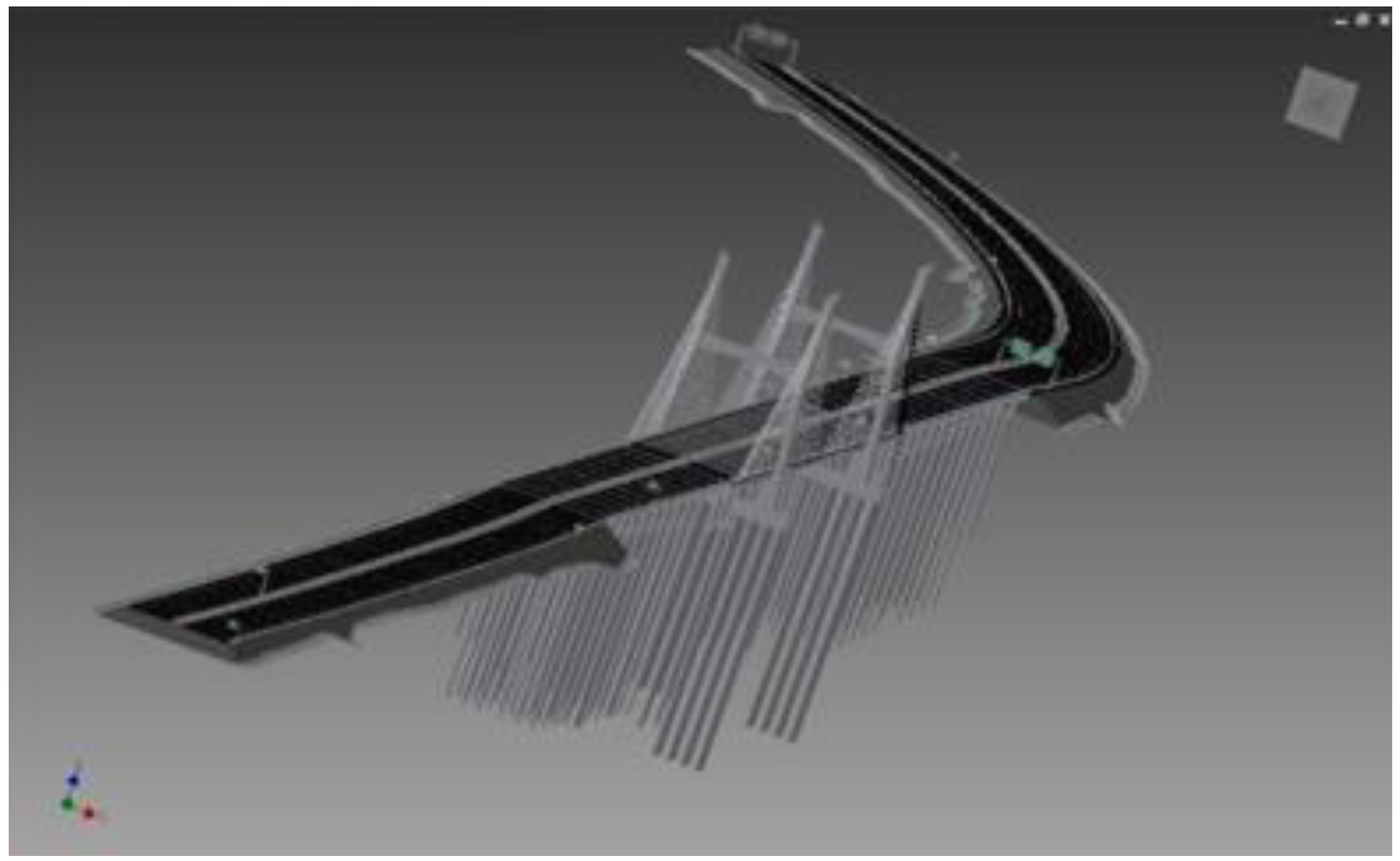
(3) Level adjustment. The requirements of the model for maintenance are somewhat different from design and construction. The model should have a hierarchical characteristic in the maintenance phase because the structural safety assessment is usually carried out upwards from the bottom layer to the top layer. Engineers could adopt the degrading function of the Autodesk Inventor to adjust the hierarchical relationship among the components. The final model of the Beijing-Hangzhou Grand Canal Bridge is shown in
Figure 5.
(4) Information integration. After completing the model building, the information of design and construction need to be attached to the bridge model. Autodesk Inventor provides common information addition. If the types of information are not provided, users also can make a customized expansion. The Bill of Material (BOM) table can be used for adding information in bulk.
3.3. Web-BIM Oriented Management
Traditional bridge management systems are usually based on computers. Users need to install all the software at computers and finish all the work in front of the computers. However, from another point of view, users are confined to those computers. Nowadays, portable devices, such as pads and cell phones, give significant convenience and flexibility to their management works. However, portable devices do not have powerful enough central processing units (CPU) or sufficient memory and cannot support heavy BIM software such as the Revit. Also, expensive BIM software needs to be installed at each user’s computer. Data such as inspection data and monitoring data usually need to be copied into some memory devices and then inputted into the system. All of these aspects make the management system expensive and inefficient. Web-BIM techniques have been developed and applied in the building management system but seldom in the bridge management system. Here, we propose the Web-BIM based management system with the lightweight techniques, thus the system can be operated at Web and could adapt to different users.
To develop the Web-BIM system, the structural model is required to be built using BIM software such as Revit, and then the model is exported and transferred to a certain file with OBJ format. Such OBJ files can then be uploaded to the server and used as a calling file to the webpage. By running the JavaScript software and calling the WebGL program, the structural model can then be transferred to a 3D web file and can be displayed on internet browsers.
For a bridge structure, especially the large-scale bridges, the converted structural model is often very huge and can hardly be displayed and operated smoothly. The lightweight model technique is necessary to reduce the data volume of the model. To realize that, a three-step lightweight approach is implemented as follows:
(1) Establish a hybrid space index. Separate the model into different scales and build the index. Trim the model to show only the information within the visual field.
(2) Establish the Levels of Detail (LOD) to the model data. Erase the information related to the unnoticeable details.
(3) Reduce the rendering batch numbers. Incorporate the objects with the same texture and render them together so that rendering efficiency can be significantly increased.
4. Design of BIM-Based Maintenance Management System
The development of the bridge management system requires the cooperation of different specialties. The system takes management as the basic requirement, information technology as the means, and bridge professional knowledge as the basis. This part introduces the detailed process of the system design.
4.1. Computer Network Design
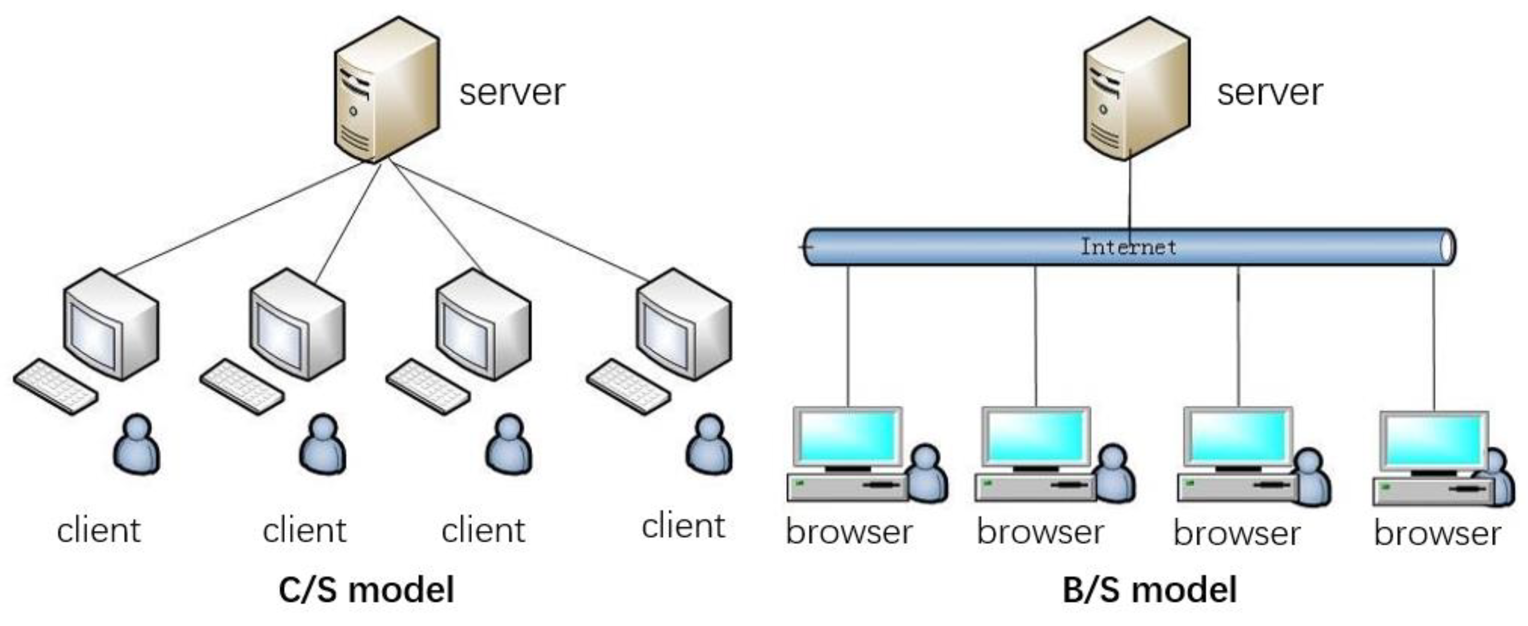
As
Figure 6 shows, C/S (client/server) models and B/S (browser/server) models are currently mainstream network structures. The C/S model belongs to a distributed application structure that can partition tasks or workloads between the providers of a resource or service, called servers, and service requesters are called clients. Often, there is communication between clients and servers over a computer network on separate hardware, but both the client and the server may reside in the same system. The device utilization is highly efficient, and the security can be ensured. However, this structure is less scalable and is generally limited to local networks. The cost for the system’s maintenance and upgrade is high. The B/S model developed along with the rise of the Internet. This model centralizes the core part of the system's functional implementation to the server, which greatly simplifies the client computer load and reduces the cost of system maintenance and up-gradation. Users only need a web browser to get access to the system without installing a client. B/S model’s security is relatively poor, which is why some measures such as permission control are needed.
In the bridge maintenance project, a large number of stakeholders are involved. The management system usually has many users, including investors, managers, and engineers. They are likely to get access to the system from different locations and with different access methods [such as a local area network (LAN), a wide area network (WAN), and Internet/Intranet]. Taking the convenience and the cost into consideration, the B/S structure is in accordance with the Web-BIM oriented management and therefore more applicable to the BIM-based management system.
4.2. System Framework
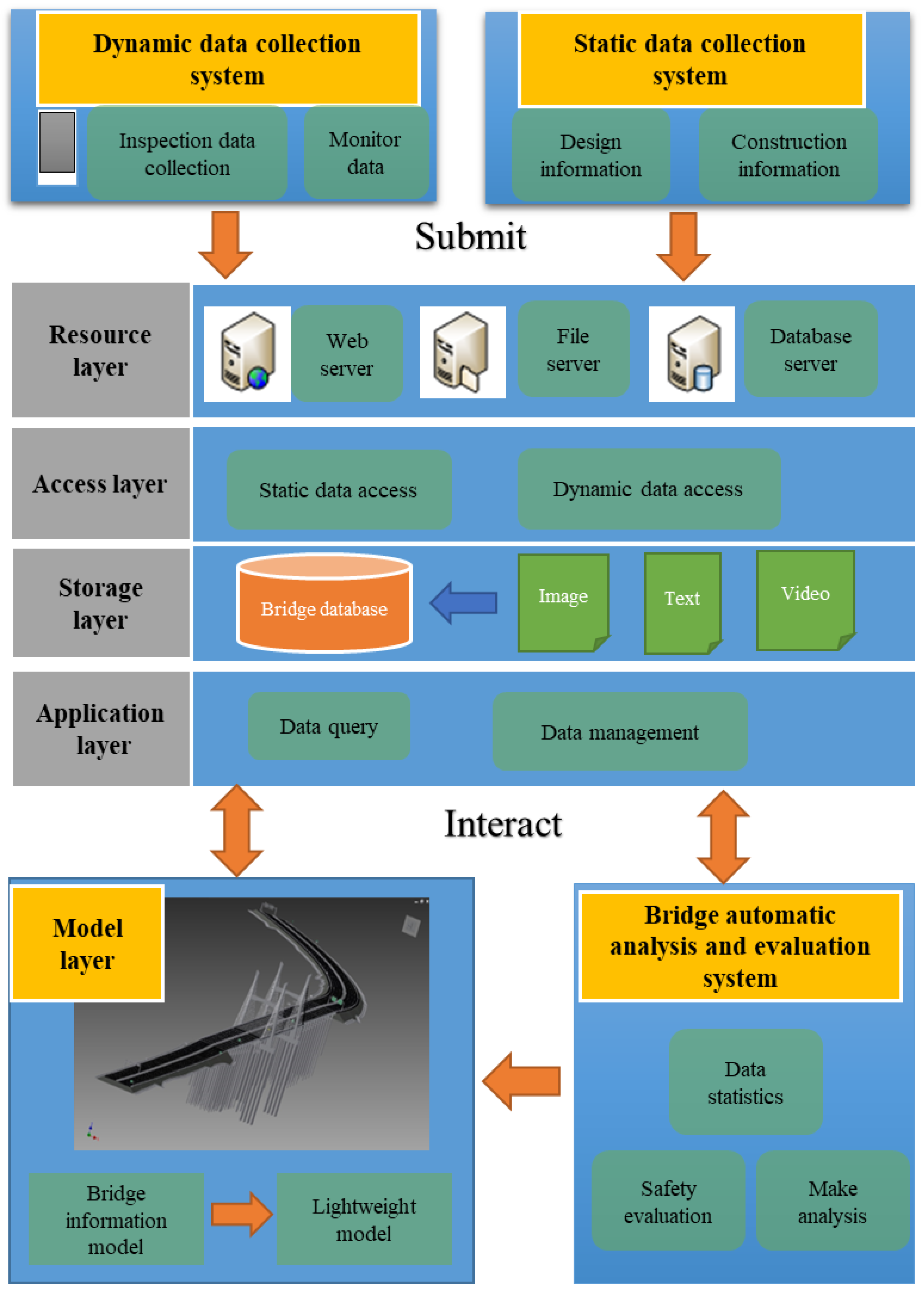
The BIM-based system mainly includes four parts: data collection system, data center, model layer, and evaluation system. The framework of the system is shown in
Figure 7, which displays the connections and the relationship between the different modules of the system.
The data center plays a significant role in the system, which consists of four layers: cloud resource layer, access layer, storage layer, and application layer. The cloud resource layer provides computing services by renting existing mature cloud computing resources for implementing various functions of the data center. The access layer provides a unified interface for the import of different types of data. The storage layer provides centralized storage of all bridge management-related data. The application layer includes the implementation of various user-oriented functions such as data query, data management, and database management tools.
The data center obtains static and dynamic data of bridges from scattered data resources through the data acquisition system of bridge maintenance. The dynamic data collection system includes two parts: the front-end collection program and the background management program. The front-end collection program is mainly the mobile APP software, which is responsible for real-time collection, input of maintenance data, and uploading information to the background management program. During the process, the background management program is responsible for managing the collected data and generating reports.
The bridge automatic analysis and evaluation system relies on the data center to obtain various types of data required for bridge condition assessment, bridge data statistics, and in-depth analysis. Through the calculation and the analysis of relevant models and algorithms, output evaluation, statistics, and analysis results are obtained and submitted to the data center. Also, the evaluation results would be presented in the bridge model.
The model layer is one of the important distinguishing points of the BIM-based bridge maintenance management system compared with the traditional systems. Because the system is based on the three-dimensional model for operations, it can make many maintenance services more intuitive and vivid. Considering that the size of the model is huge and takes up too much memory, the model is then transformed into a lightweight model to better display in the portable terminals. The model layer correlates the information such as inspection, evaluation, and maintenance reinforcement in the database with the component of the bridge, thus different information can be displayed through the model. Therefore, the model layer part effectively connects the data layer part and the functional layer part together and plays a central role in the whole system framework.
5. The application on the Grand Canal Bridge
5.1. Project Overview
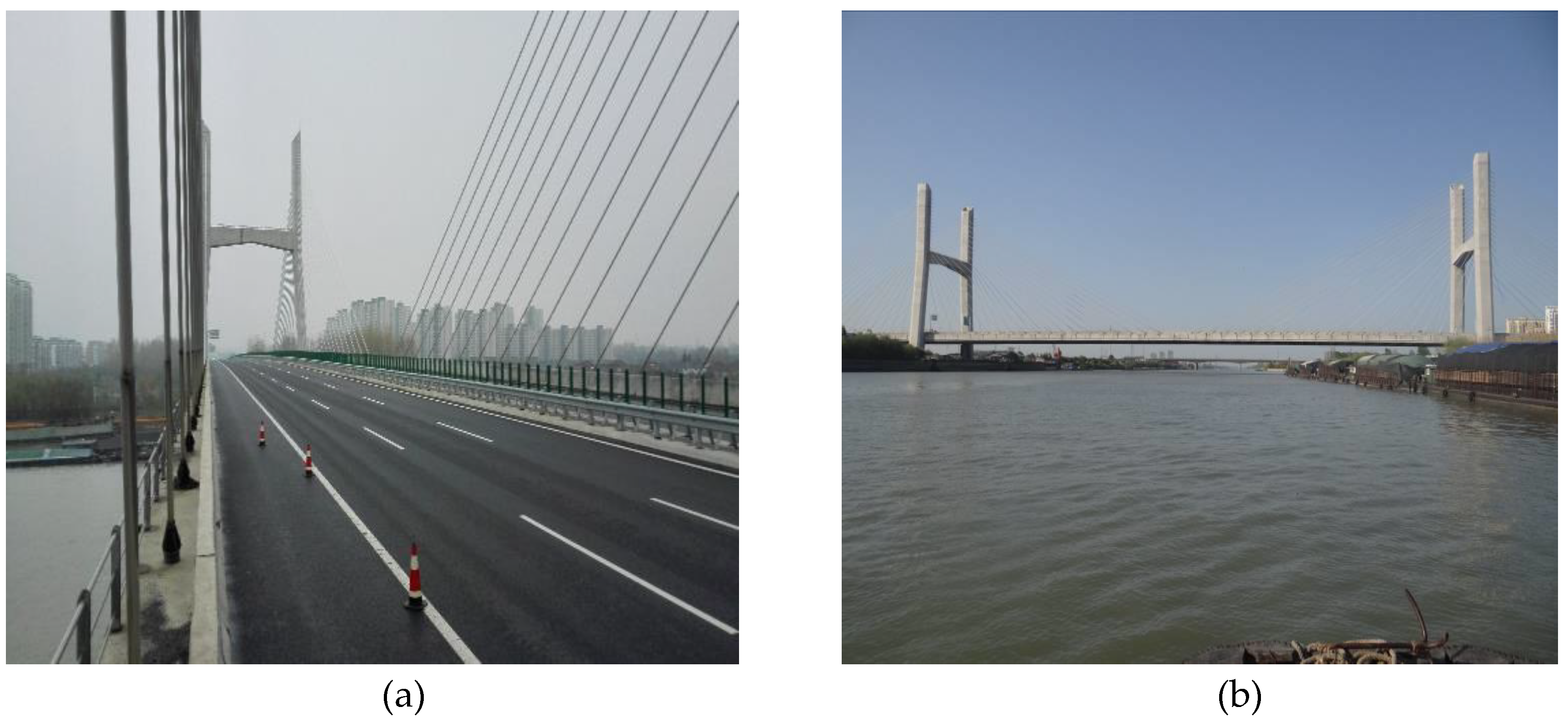
The Beijing–Hangzhou Grand Canal is the longest artificial river in the world, starting at Beijing, passing through Tianjin and provinces of Hebei, Shandong, Jiangsu, and Zhejiang, and finally arriving in the city of Hangzhou. The total length of the Grand Canal reaches 1776 kilometers. The Beijing-Hangzhou Grand Canal Bridge is located at the south of Yangzhou, Ning yang Expressway. As is shown in
Figure 8, the main bridge across the Grand Canal is a double-tower semi-floating system concrete cable-stayed bridge, the length of which is 464 meters (108 m + 248 m + 108 m). On each side of the main bridge is 11-span (6 × 30 m + 5 × 30 m) prefabricated, prestressed concrete approach bridge.
5.2. Implementation in Grand Canal Bridge
Beijing-Hangzhou Grand Canal Bridge is classified in the second level according to its present structural condition. Many shrinkage cracks have appeared on the cable-stayed bridge tower and the main beams of the bridge. Some protective covers of the cable anchorages have deformed severely. Moreover, there are a lot of longitudinal cracks on the box girder of the approach bridge and transverse cracks on the wet joints. Some of the laminated rubber bearings have been damaged.
In order to realize the effective management and maintenance of the Beijing-Hangzhou Grand Canal Bridge, the BIM-based management system was built. Firstly, the bridge model was established using Inventor, and a special lightweight processing that could significantly reduce the data volume was implemented to form the model layer. Then, the lightweight model was connected to the GIS system, which showed the geographic information of the bridge, as
Figure 9 shows. Also, it is associated with the bridge maintenance information database. The database is an important foundation for further evaluation and decision-making, which are the core parts of the function layer.
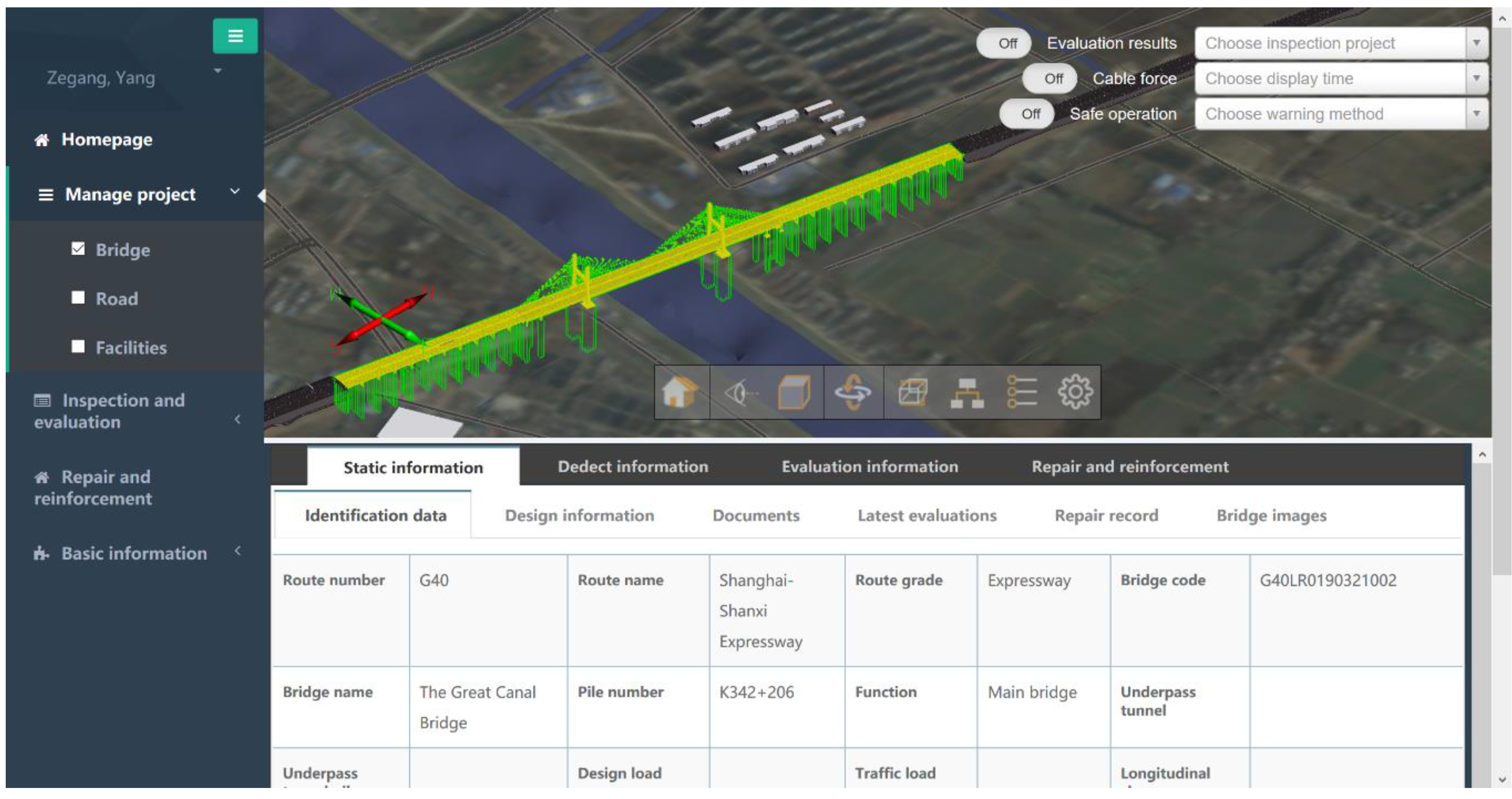
With the Web-BIM oriented approach, the stakeholders of the bridge can get access to the system through the Internet. The homepage of the system includes three parts: function modules, bridge model, and static information, as
Figure 9 shows.
5.2.1. Static Information Module
Static information management in this BMS platform was established and is shown in
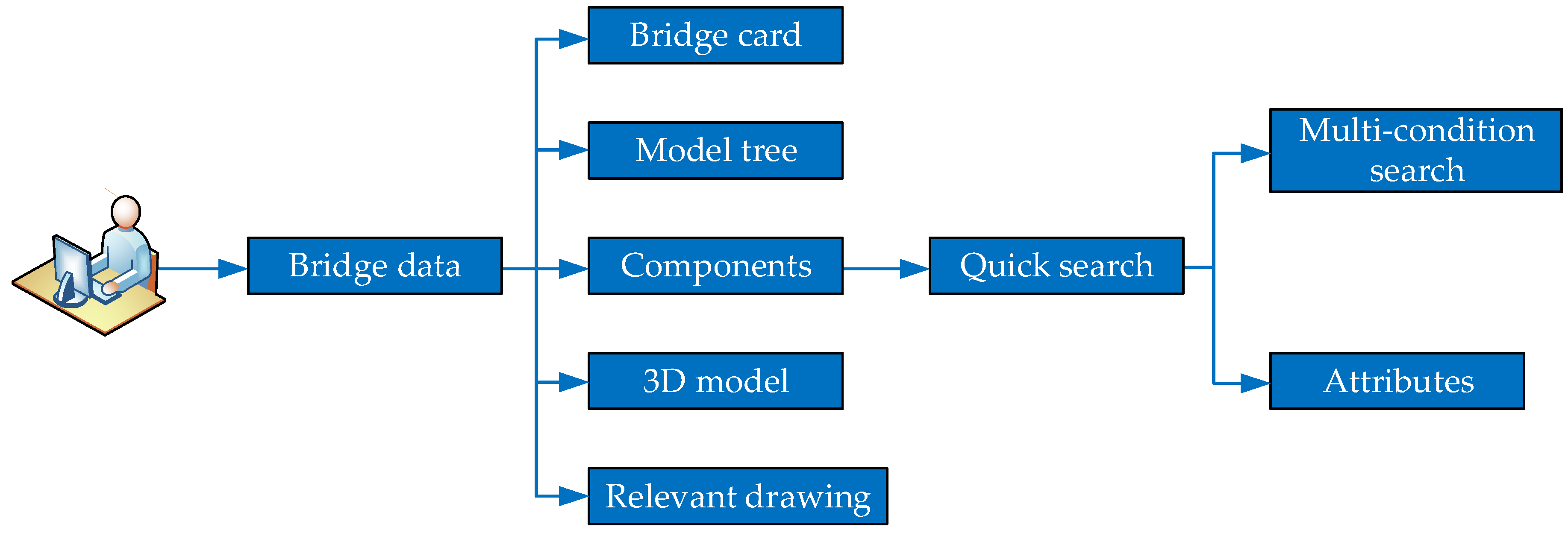
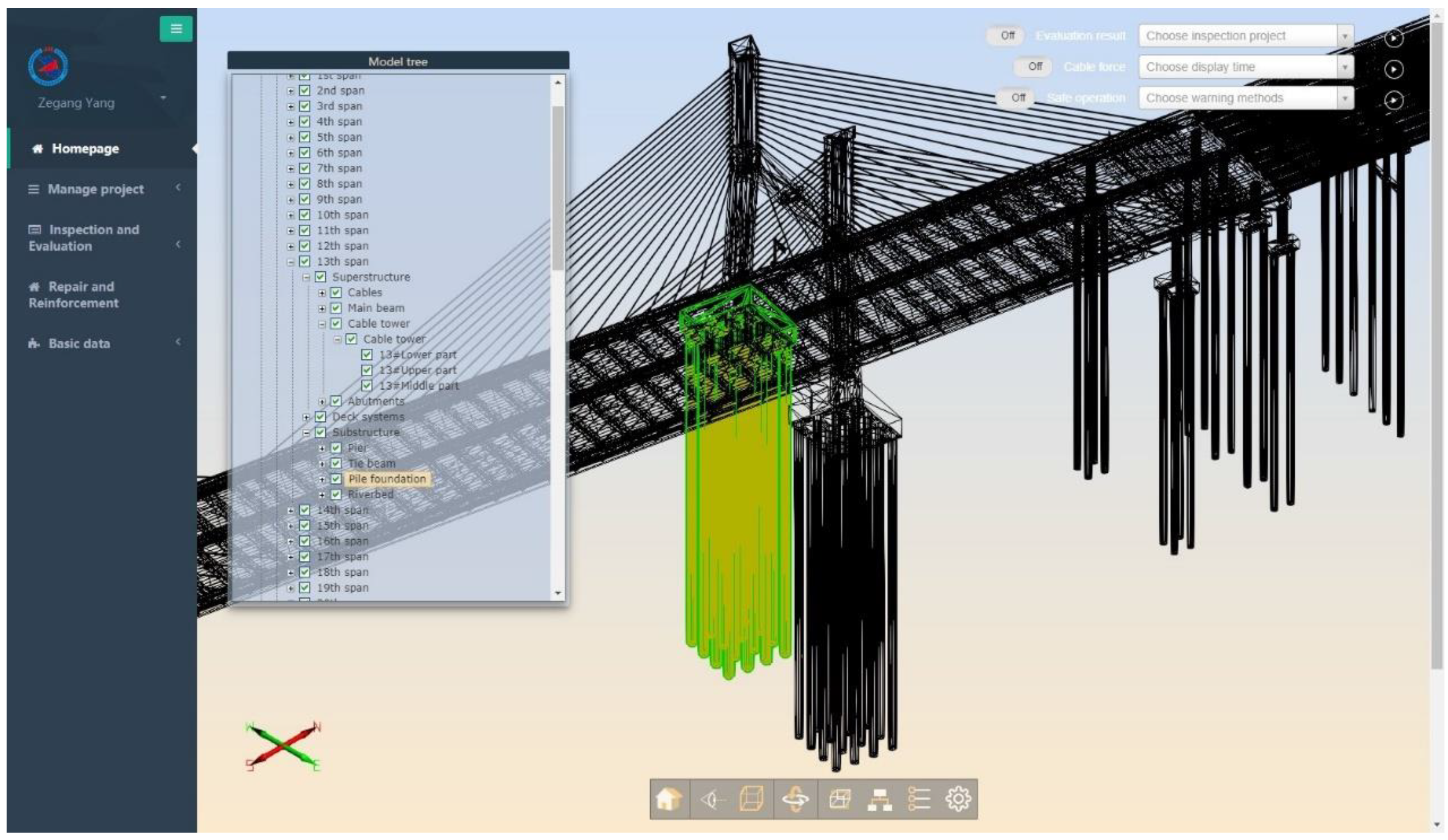
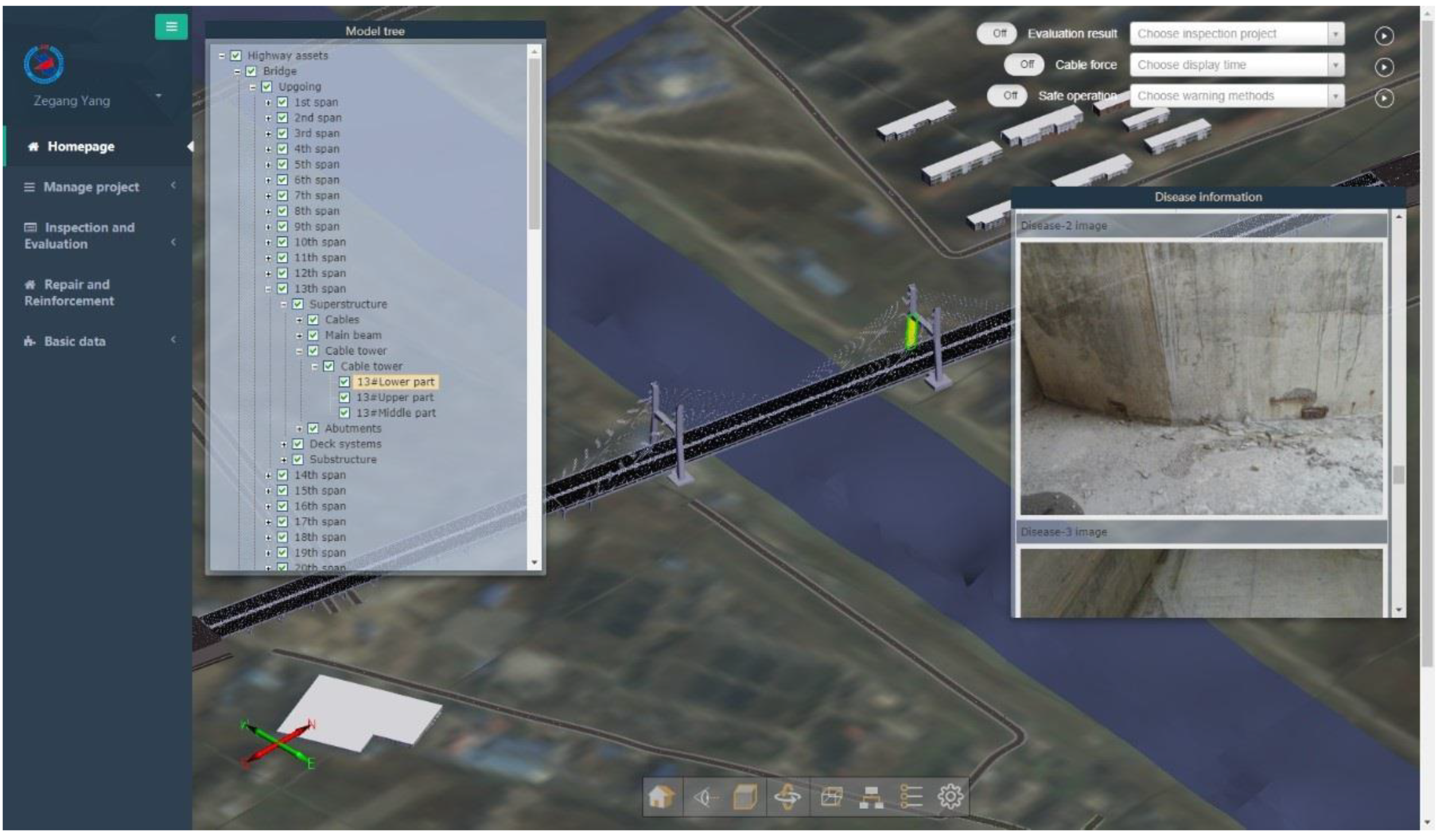
Figure 10. This system accumulates the scattered information in the design and the construction phases to formulate the “bridge life card”. The results indicate that users could choose the members in the bridge model to query corresponding static information such as design drawings, design parameters, material usage, etc. Moreover, the model tree is one type of dendrogram based on the hierarchy characteristic of the model, which is provided for accurate localization of members in the model. As
Figure 11 shows, users can unfold the dendrogram to click the pile foundation of thirteenth span, which was highlighted in the model automatically.
5.2.2. Inspection and Evaluation Module
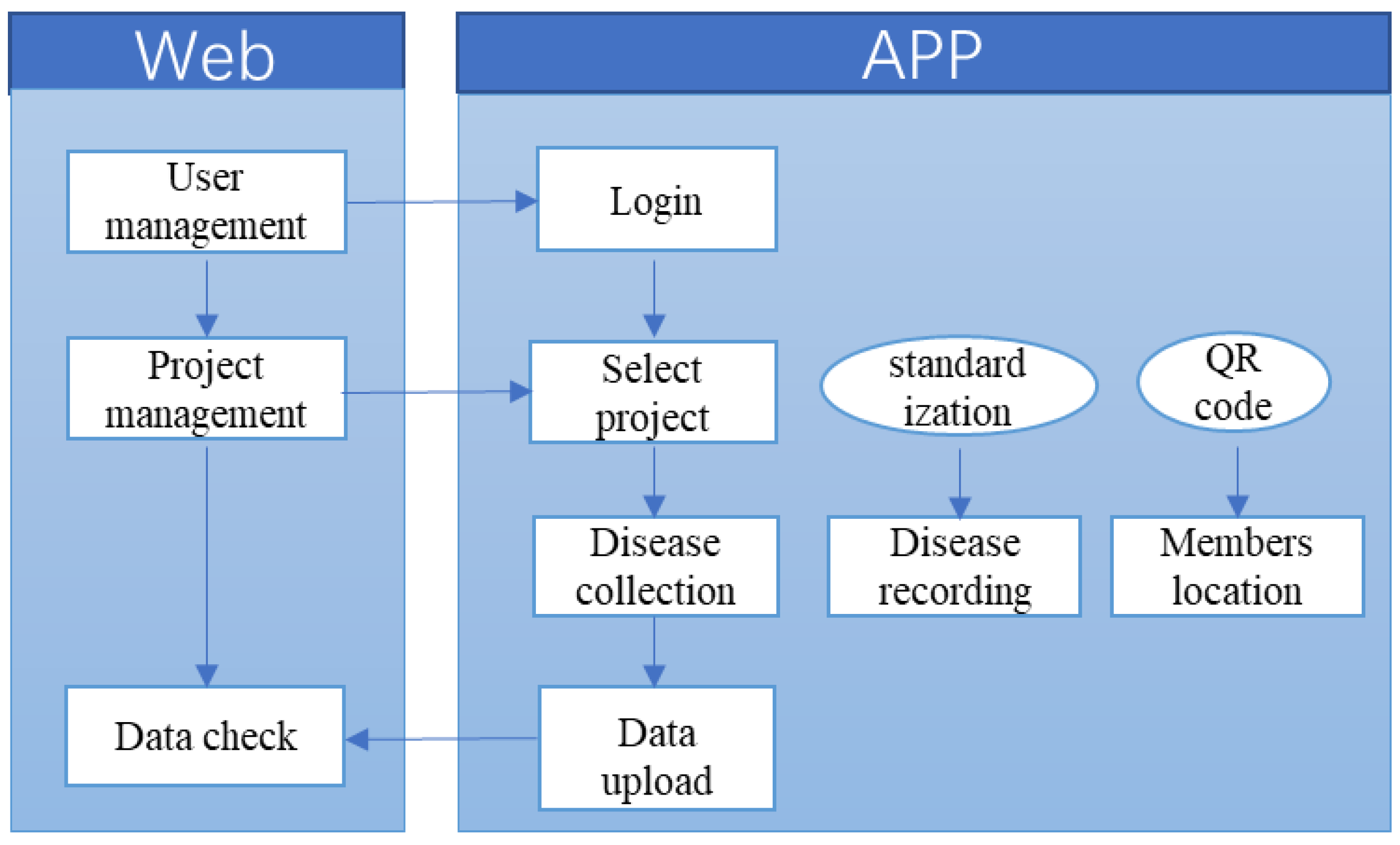
Inspection and evaluation have great significance for BMS. Based on this, we firstly designed an inspection workflow to show how the bridge managers create and manage the inspection projects on the website. As
Figure 12 shows, the inspectors could log into the system through a mobile application at the spots, collect all the structural defect information of the bridge, and then submit to the system. Large bridges have high numbers of members; inspectors can localize the member quickly by choosing it on the lightweight bridge model. In order to improve the accuracy of defect information description, the system provides a standardized template according to the statistics and the classification of common defects. After inspectors submit the defect information, managers can check it in the system, as
Figure 13 shows.
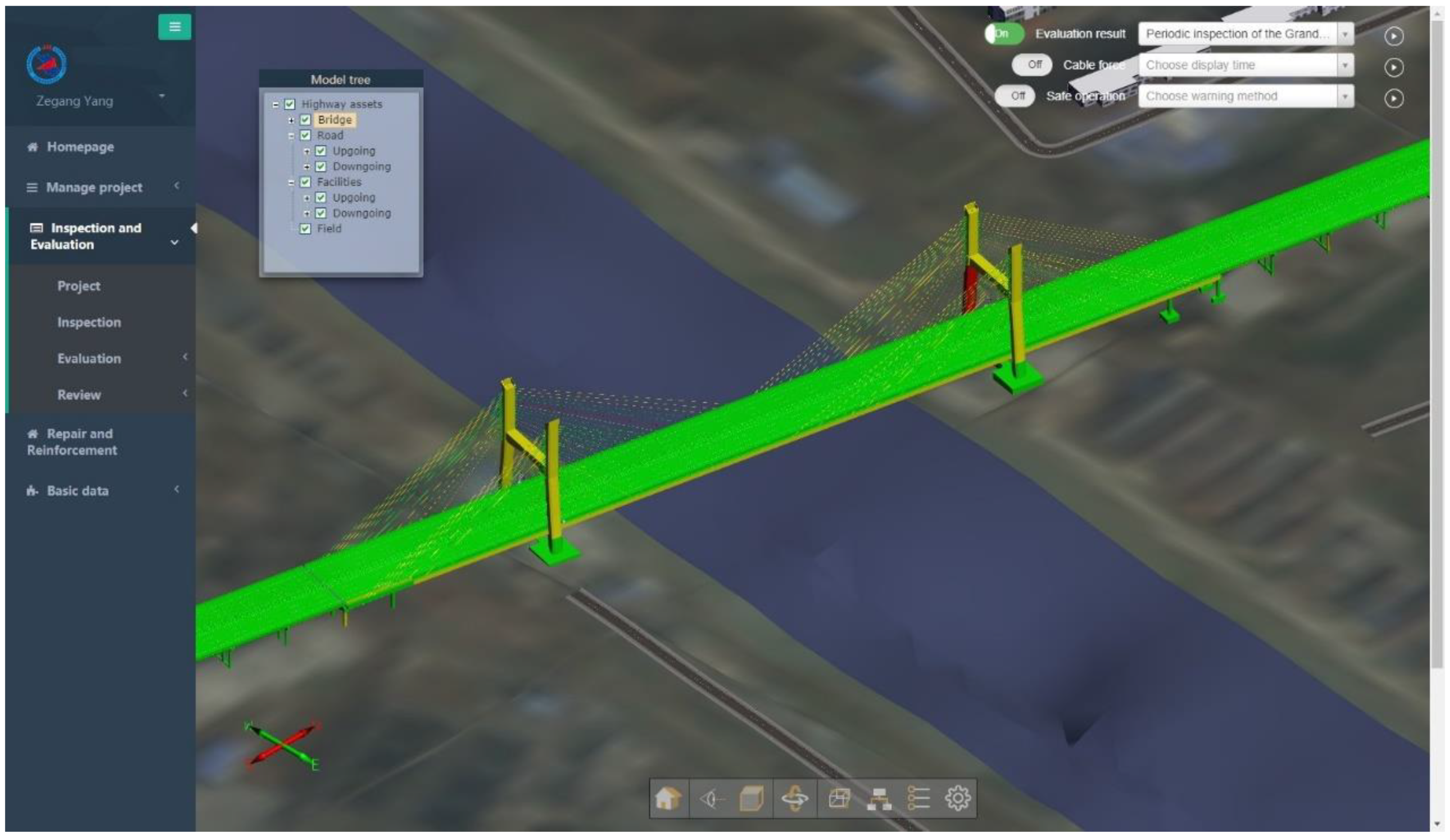
Based on the defect information collected by the mobile terminal, the evaluation system can make automatic analysis and calculate the scores of the members according to the bridge maintenance standard. Then, the bridge information model displays different colors on the members to intuitively describe the technical condition of different levels of the whole bridge.
Figure 14 shows the evaluation results of the Grand Canal Bridge. The members in green color stayed in a safe state, and the members in yellow suffered light damage. The red color means the members have been damaged severely, and corresponding measurement should be considered.
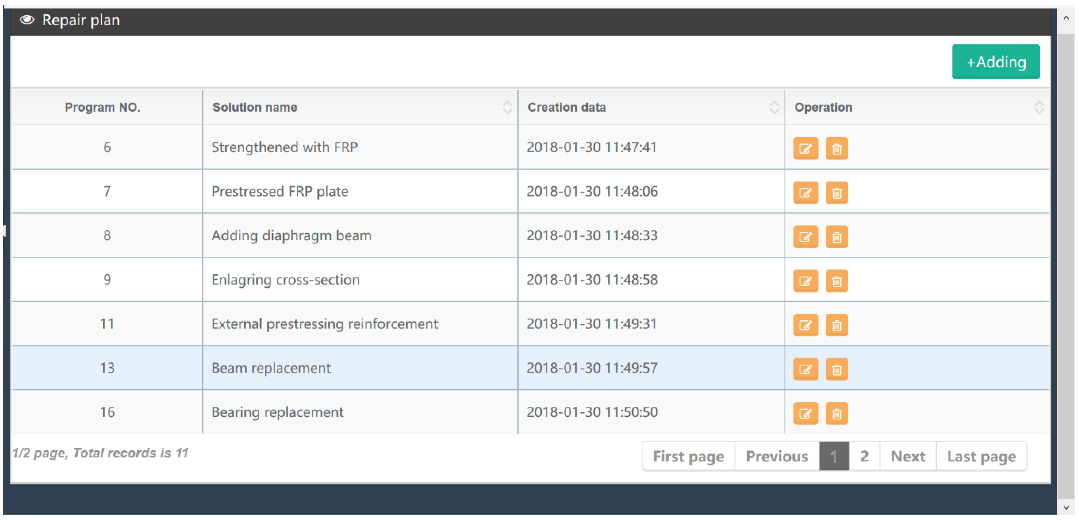
Repair and reinforcement information of the bridge is stored in the system and can be searched by users. The defects of the bridge, such as cracking, usually develop as the time grows. When the defect develops to a certain extent and threatens the structure safety, the system automatically sends text messages to bridge managers to remind them to create a repair and reinforcement project. Besides, the system regularly generates statistics, graphs, and tables according to inspection and monitoring information. Based on these functions, the BIM-based system helps to make auxiliary maintenance decisions. As shown in
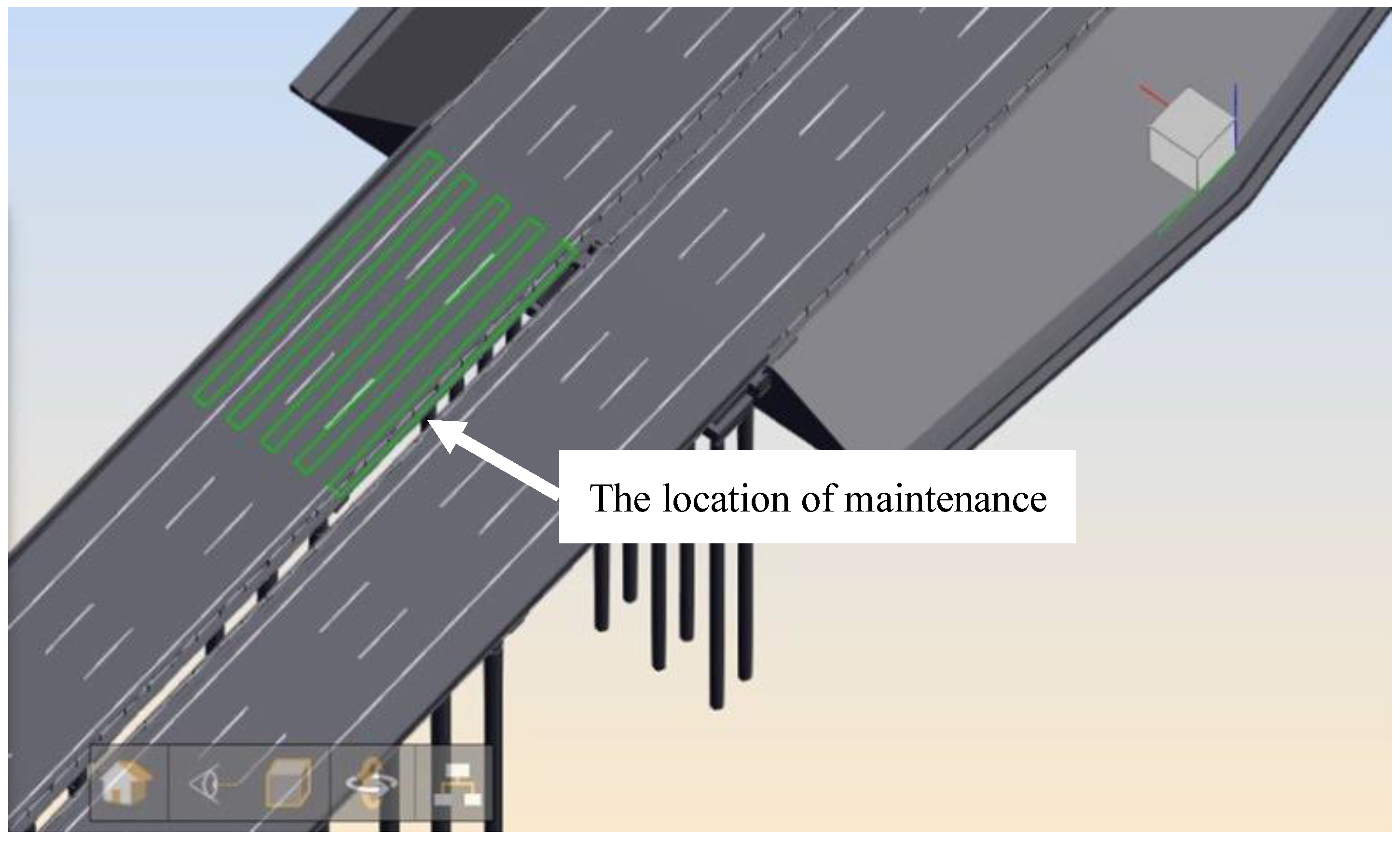
Figure 15, users can view the relevant information on the repair plan in this module. After this reinforcement and repair, one can determine whether the maintenance is qualified or not according to the actual situation. The maintenance can be displayed through the model, and the repair results can be check by the managers, as shown in
Figure 16. Based on this, the detailed information of the location and the effects of this reinforcement can be obtained.
5.3. Results and System Benefits
After this maintenance system was built, it was applied to the company in charge of the maintenance of the Grand Canal Bridge. Feedback was quite positive. Web-BIM oriented management mode allows all users easy access to the system. Portable devices have also been applied in the bridge inspection procedure. By scanning the tag at a component, the component can be identified, and related structural defects can be directly reported by text description, picture, or report via the portable device on site. The established BMS also provides a good platform upon which all users can collaboratively work together. Owners, engineers, economists, managers, and other related staff can share their data, release/receive tasks, track the progress, and even communicate with each other. Multi-scale visualization of the bridge model helps to understand the structural condition easily. Structural analysis and diagnosis algorithms can be embedded in the system and make the system smart. All of these make the maintenance activity very convenient and efficient. It will be helpful for the maintenance of many bridges in China, and its application is promising.
6. Conclusions
The number of bridges has increased significantly within the last three decades in China. The large number of the bridges, however, brings great pressure to the owners, the industry, and even the government for their maintenance. An effective and efficient bridge management system has become indispensable to meet the massive demand of bridge maintenance.
In this paper, a bridge management system based on the BIM technology was proposed, developed, and introduced. Necessary IFC and IFD standards were proposed as supplements according to the actual needs of bridge maintenance, filling the blank in BIM standards of the bridge industry of China. Web-BIM oriented management was proposed, and portable devices were introduced to the system as well as the maintenance activity. The bridge modeling method was developed to build the proper information model for bridges. Lightweight methods were also introduced to reduce the volume of the model and make the system run smoothly. The system framework and functions were designed. A BMS for a real long-span cable-stayed bridge was also built and established, which incorporates the GIS and satisfies the main maintenance functions, such as information management, bridge inspection, condition evaluation, repair and reinforcement, multi-scale visualization, and collaborative management.
The proposed BIM-based bridge management system could improve management efficiency and satisfy the need for maintenance of substantive bridges in China. The future of such a management system is promising. However, at present, the BIM model cannot be connected to the finite element model (FEM), which strongly limits the structural analysis ability. Also, data in the system are not mined deep enough. Integration of the BIM model and the FEM model as well as the deep mining of data using big data technology will make the system much more powerful and useful and could provide a better platform for efficient bridge management.
Author Contributions
Conceptualization, C.W. and Y.D.; methodology, C.W. and Y.D.; software, Z.X., Z.Y. and Y.X.; formal analysis, Z.Z. and S.L.; investigation, Z.Z. and S.L.; data collection, Z.X. and F.Y.; writing—original draft preparation, Z.Z. and S.L.; writing—review and editing, C.W. and Z.Z.; funding acquisition, C.W. and Y.D.; supervision, C.W.
Funding
The research was supported by the National Key Research and Development Program of China (2017YFC0806001), the National Natural Science Foundation of China (No. 51578140), the Postgraduate Research & Practice Innovation Program of Jiangsu Province (No. SJCX18_0027).
Conflicts of Interest
There is no conflict of interest.
References
- Zhang, L.; Zhou, G.; Han, Y.; Lin, H.; Wu, Y. Application of Internet of Things Technology and Convolutional Neural Network Model in Bridge Crack Detection. IEEE Access 2018, 6, 39442–39451. [Google Scholar] [CrossRef]
- Qi, J.; Issa, R.R.A.; Olbina, S.; Hinze, J. Use of Building Information Modeling in Design to Prevent Construction Worker Falls. J. Comput. Civ. Eng. 2014, 28, A4014008. [Google Scholar] [CrossRef]
- Gibb, A.; Haslam, R.; Gyi, D.; Hide, S.; Duff, R. What Causes Accidents? Institution of Civil Engineers: London, UK, 2006; Volume 159, pp. 46–50. [Google Scholar]
- Yin, Z.H.; Li, Y.F.; Guo, J.; Li, Y. Integration Research and Design of the Bridge Maintenance Management System. Procedia Eng. 2011, 15, 5429–5434. [Google Scholar] [CrossRef]
- Söderqvist, M.-K.; Veijola, M. The Finnish Bridge Management System. Struct. Eng. Int. 1998, 8, 315–319. [Google Scholar] [CrossRef]
- Lauridsen, J.; Bjerrum, J.; Andersen, N.H.; Lassen, B. Creating a Bridge Management System. Struct. Eng. Int. 1998, 8, 216–220. [Google Scholar] [CrossRef]
- Haardt, P. Development of a Bridge Management System for the German Highway Network. In Proceedings of the First International Conference on Bridge Maintenance, Safety and Management. IABMAS, Barcelona, Spain, 14–17 July 2002. [Google Scholar]
- Miyamoto, A.; Kawamura, K.; Nakamura, H. Bridge Management System and Maintenance Optimization for Existing Bridges. Comput. Civ. Infrastruct. Eng. 2000, 15, 45–55. [Google Scholar] [CrossRef]
- Dai, K.; Smith, B.H.; Chen, S.E.; Sun, L. Comparative study of bridge management programmes and practices in the USA and China. Struct. Infrastruct. Eng. 2014, 10, 577–588. [Google Scholar] [CrossRef]
- Costin, A.; Adibfar, A.; Hu, H.; Chen, S.S. Building Information Modeling (BIM) for transportation Infrastructure—Literature review, applications, challenges, and recommendations. Autom. Constr. 2018, 94, 257–281. [Google Scholar] [CrossRef]
- Eastman, C.; Teicholz, P.; Sacks, R.; Liston, K. BIM Handbook: A Guide to Building Information Modeling For Owners, Managers, Designers, Engineers and Contractors; Wiley: Hoboken, NJ, USA, 2011. [Google Scholar]
- Gao, J.; Fischer, M. Framework and Case Studies Comparing Implementations and Impacts of 3D/4D Modeling across Projects; Stanford University: Stanford, CA, USA, 2008. [Google Scholar]
- Martínez-Aires, M.D.; López-Alonso, M.; Martínez-Rojas, M. Building information modeling and safety management: A systematic review. Saf. Sci. 2018, 101, 11–18. [Google Scholar] [CrossRef]
- Shin, H.; Lee, H.; Oh, S.; Chen, J. Analysis and Design of Reinforced Concrete Bridge Column Based on BIM. Procedia Eng. 2011, 14, 2160–2163. [Google Scholar] [CrossRef] [Green Version]
- Liu, W.; Guo, H.; Li, H.; Li, Y. Retracted: Using BIM to Improve the Design and Construction of Bridge Projects: A Case Study of a Long-Span Steel-Box Arch Bridge Project. Int. J. Adv. Robot. Syst. 2014, 11, 125. [Google Scholar] [CrossRef]
- Lee, K.M.; Lee, Y.B.; Shim, C.S.; Park, K.L.; Shim, C. Bridge information models for construction of a concrete box-girder bridge. Struct. Infrastruct. Eng. 2012, 8, 687–703. [Google Scholar] [CrossRef]
- Shim, C.; Yun, N.; Song, H.; Shim, C. Application of 3D Bridge Information Modeling to Design and Construction of Bridges. Procedia Eng. 2011, 14, 95–99. [Google Scholar] [CrossRef] [Green Version]
- Fanning, B.; Clevenger, C.M.; Ozbek, M.E.; Mahmoud, H. Implementing BIM on infrastructure: Comparison of two bridge construction projects. Pract. Period. Struct. Des. Constr. 2014, 20, 04014044. [Google Scholar] [CrossRef]
- McGuire, B.; Atadero, R.; Clevenger, C.; Ozbek, M. Bridge Information Modeling for Inspection and Evaluation. J. Bridg. Eng. 2016, 21, 04015076. [Google Scholar] [CrossRef]
- Abudayyeh, O.; Al-Battaineh, H.T. As-Built Information Model for Bridge Maintenance. J. Comput. Civ. Eng. 2003, 17, 105–112. [Google Scholar] [CrossRef]
- Marzouk, M.M.; Hisham, M. Bridge Information Modeling in Sustainable bridge Management. In Proceedings of the Integrating Sustainability Practices in the Construction Industry, Kansas City, MI, USA, 23–25 March 2011; pp. 457–466. [Google Scholar]
- Okasha, N.M.; Frangopol, D.M. Computational platform for the integrated life-cycle management of highway bridges. Eng. Struct. 2011, 33, 2145–2153. [Google Scholar] [CrossRef]
- Shim, C.S.; Kang, H.R.; Dang, N.S.; Lee, D.K. Development of BIM-based bridge maintenance system for cable-stayed bridges. Smart Struct. Syst. 2017, 20, 697–708. [Google Scholar]
- She, T.H.; Sarshar, M. A Geographic Information System (GIS)-Based Bridge Management System. Comput. Civ. Infrastruct. Eng. 1999, 14, 417–427. [Google Scholar] [CrossRef]
- Estes, A.C.; Frangopol, D.M. Updating Bridge Reliability Based on Bridge Management Systems Visual Inspection Results. J. Bridg. Eng. 2003, 8, 374–382. [Google Scholar] [CrossRef] [Green Version]
- Roelfstra, G.; Hajdin, R.; Adey, B.; Brühwiler, E. Condition Evolution in Bridge Management Systems and Corrosion-Induced Deterioration. J. Bridg. Eng. 2004, 9, 268–277. [Google Scholar] [CrossRef]
- NIBS. United States National Building Information Modeling Standard Version 1—Part 1: Overview, Principles, and Methodologies, Final Report; National Institutes of Building Sciences: Washington, DC, USA, 2007. [Google Scholar]
- Ma, Z.L.; Wei, Z.H.; Wu, S.; Zhe, L. Application and extension of the IFC standard in construction cost estimating for tendering in China. Autom. Constr. 2011, 20, 196–204. [Google Scholar]
- Laakso, M.; Kiviniemi, A.O. The IFC standard: A review of history, development, and standardization, information technology. ITcon 2012, 17, 134–161. [Google Scholar]
- Li, Z.; Man, Q. Research Front and Review of BIM Based on China Knowledge Resource Integrated Database. In Proceedings of the International Conference on Construction and Real Estate Management, Kunming, China, 27–28 September 2014; pp. 911–921. [Google Scholar]
- ISO 120096-2. Building Construction-Organization of Information about Construction Works-Part2: Framework for Classification of Information. 2015. Available online: https://www.sis.se/api/document/preview/899471/ (accessed on 17 August 2019).
Figure 1.
Expression of attribute information using Industry Foundation Classes (IFC) extension.
Figure 1.
Expression of attribute information using Industry Foundation Classes (IFC) extension.
Figure 2.
Classification framework.
Figure 2.
Classification framework.
Figure 3.
Coding principles using International Framework for Dictionaries (IFD) standard extension: (a) bridge type, (b) bridge component.
Figure 3.
Coding principles using International Framework for Dictionaries (IFD) standard extension: (a) bridge type, (b) bridge component.
Figure 4.
Modeling process.
Figure 4.
Modeling process.
Figure 5.
The Grand Canal Bridge model.
Figure 5.
The Grand Canal Bridge model.
Figure 6.
Computer network.
Figure 6.
Computer network.
Figure 7.
System framework.
Figure 7.
System framework.
Figure 8.
The Grand Canal Bridge: (a) bridge deck; (b) whole bridge.
Figure 8.
The Grand Canal Bridge: (a) bridge deck; (b) whole bridge.
Figure 9.
System homepage.
Figure 9.
System homepage.
Figure 10.
Visualization management of static information.
Figure 10.
Visualization management of static information.
Figure 11.
Pile foundation of thirteenth span in the model tree.
Figure 11.
Pile foundation of thirteenth span in the model tree.
Figure 12.
Inspection workflow.
Figure 12.
Inspection workflow.
Figure 13.
Structural defect information in inspection module.
Figure 13.
Structural defect information in inspection module.
Figure 14.
Evaluation module.
Figure 14.
Evaluation module.
Figure 15.
The repair plan of bridge components.
Figure 15.
The repair plan of bridge components.
Figure 16.
The information of component maintenance in repair and reinforcement module.
Figure 16.
The information of component maintenance in repair and reinforcement module.
Table 1.
Attribute set definition of maintenance information.
Table 1.
Attribute set definition of maintenance information.
| Attribute Set Name | Applicable Entity | Applicable Type | Definition |
|---|
| Pset-diseasetype | IfcBuildingElement | UserDefined | Disease type |
| Pset-reinforcetype | IfcBuildingElement | UserDefined | Reinforcement method |
Table 2.
Attribute definition of structural defect information.
Table 2.
Attribute definition of structural defect information.
| Attribute Name | Attribute Type | Data Type | Definition |
|---|
| Crack | IfcPropertySingleValue | IfcBoolean | Concrete crack |
| HungrySpots | IfcPropertySingleValue | IfcBoolean | Voids and pits of concrete |
| Spalling | IfcPropertySingleValue | IfcBoolean | Concrete spalling |
| Corrosion | IfcPropertySingleValue | IfcBoolean | Corrosion of steel bar |
| Deformation | IfcPropertySingleValue | IfcBoolean | Excessive deformation |
Table 3.
Attribute definition of reinforcement information.
Table 3.
Attribute definition of reinforcement information.
| Attribute Name | Attribute Type | Data Type | Definition |
|---|
| ElargeSection | IfcPropertySingleValue | IfcBoolean | Elarging section |
| BondFRP | IfcPropertySingleValue | IfcBoolean | Bonding FRP |
| BondSteel | IfcPropertySingleValue | IfcBoolean | Bonding steel plate |
| ExternalPrestress | IfcPropertySingleValue | IfcBoolean | External prestressing |
Table 4.
Attribute definition of crack.
Table 4.
Attribute definition of crack.
| Attribute Name | Attribute Type | Data Type | Definition |
|---|
| CrackDirect | IfcPropertySingleValue | Ifclabel | Direction of crack |
| CrackLength | IfcPropertySingleValue | Ifcreal | Length of crack |
| CrackWidth | IfcPropertySingleValue | Ifcreal | Width of crack |
Table 5.
Engineering behavior information.
Table 5.
Engineering behavior information.
| Coding | First Level | Second Level | Third Level | Forth Level |
|---|
| 74-10 00 00 | Investment | | | |
| 74-20 00 00 | Design | | | |
| 74-30 00 00 | Construction | | | |
| 74-40 00 00 | Maintenance | | | |
| … | … | … | … | … |
| 74-40 10 00 | | Inspection | | |
| 74-40 10 10 | | | Daily Inspection | |
| 74-40 10 10 10 | | | | Day patrol |
| 74-40 10 10 20 | | | | Night patrol |
Table 6.
Bridge maintenance information.
Table 6.
Bridge maintenance information.
| Coding | First Level | Second Level | Third Level |
|---|
| 78-10 00 00 | Defect | | |
| 78-10 01 00 | | Crack | |
| 78-10 01 01 | | | Vertical crack |
| 78-10 01 02 | | | Horizontal crack |
| 78-10 01 03 | | | Longitudinal crack |
| … | … | … | … |
| 78-10 01 04 | | | Oblique crack |
| 78-10 01 05 | | | Bursting crack |
| 78-10 01 06 | | | Circumferential crack |
| 78-10 01 07 | | | Reticulate crack |
© 2019 by the authors. Licensee MDPI, Basel, Switzerland. This article is an open access article distributed under the terms and conditions of the Creative Commons Attribution (CC BY) license (http://creativecommons.org/licenses/by/4.0/).

 ,
, 


