Article

Secondary Development and Application of Bio-Inspired Isolation System

1
Department of Disaster Mitigation for Structures, Tongji University, Shanghai 200092, China
2
Shanghai RB Science & Technology Co., Ltd., Shanghai 201400, China
*
Author to whom correspondence should be addressed.
Sustainability 2019, 11(1), 278; https://doi.org/10.3390/su11010278
Submission received: 6 December 2018 / Revised: 3 January 2019 / Accepted: 4 January 2019 / Published: 8 January 2019

Abstract

:
Near-fault pulse motions will cause excessive and much larger base displacement in traditional isolated structures than common earthquake motions. The new isolation system inspired by the “sacrificial bonds and hidden length” biomechanics of an abalone shell can control the base displacement efficiently and reach almost the same vibration isolation efficiency as a semi-active control system. The current research is confined to the lumped mass model and cannot uncover the exact performance of isolators and structures in practical applications. A user subroutine is developed based on the interface of UEL in Abaqus. Subsequent verification has been done in both the lumped mass model and 3D complex model with Abaqus, Matlab/Simulink, and SAP2000. It can be revealed from the comparative results that the calculation accuracy of the secondary developed user subroutine can meet the demand of design and research.

1. Introduction

Earthquakes have caused an inestimable loss of life and property for human beings, both directly and indirectly. The urgent demand for minimizing losses in seismic events makes the technology of earthquake-resistance more popular than ever before. The current technique to reduce seismic action can be simply classified as vibration absorption and vibration isolation [1,2,3,4].
In vibration absorption, displacement-dependent dampers or velocity-dependent dampers are installed at the position where relatively large deformation occurs. The base isolation technique is an effective method to reduce earthquake action by adding an additional isolation layer [5,6,7,8,9]. This technology can isolate the earthquake energy and prevent it from propagating upwards, therefore degenerating the response of the superstructure. After adopting the base isolation technique, the superstructure can only suffer 1/2~1/3 of ground seismic action. In the present work, the adopted strategy is to elongate the fundamental period of the structure with respect to the fundamental period of the conventional fixed-base structure. The fundamental period of the isolated structure will be shifted from the dominant period of the earthquake ground motion. The modern vibration absorption and vibration base isolation technique dates back to 1891. Kawai Hiroshi, from Japan, came up with the idea of a “structure isolated from ground motion” for the first time. The device mainly consisted of logs which could roll in a horizontal direction or, in other words, release the degree of freedom in the horizontal direction.
An isolated structure performs well only in the common far-field earthquake. For structures located near the epicenter, it may suffer from the intense near-fault ground motions which may contain a long-period velocity pulse and displacement pulse [10,11,12,13,14]. This kind of intense near-fault ground motion will cause excessive horizontal shear deformation, which is much larger than the ultimate deformation capacity of the isolators, thus rendering them invalid. In general cases, damping devices, like a viscous damper or viscoelastic damper, are usually applied in the isolation layer in order to decrease the base displacement, but this method will lower the vibration isolation efficiency in the superstructure [15,16]. To resolve the contradiction between the dynamic response of the superstructure and isolation layer, researchers have proposed active control, semi-active control, and hybrid control.
The active control strategy employs an exterior control force to directly control the dynamic response by a rational optimized algorithm [17,18,19,20]. However, the active control strategy has its own shortcomings. Firstly, electric power cannot always be supplied, especially during an earthquake. Secondly, the control mechanism is too complex to keep working without any malfunction. Finally, it may take too many human and financial resources to maintain it. Considering all these factors, the active control system is seldom employed in practical projects. The semi-active control system changes the stiffness or damping by inputting a modest amount of energy to the feedback of the dynamic response of the structure and the external excitation [21,22,23,24]. Like the active control system, semi-active control fails to be extensively applied as a result of its sensitivity to the frequency band of excitation or other factors. The hybrid control system is a combination of the active control system and passive control system. This strategy can avoid the shortcomings of both individual systems, but still has its own inadaptation [25,26].
Henry T.Y. Yang proposed a new energy dissipation brace based on the biomechanism of “sacrificial bonds and hidden length” inspired from an abalone shell [27]. It was verified from numerical simulation and tests that the new energy dissipation brace can reach an efficiency equal to that of the semi-active control method. Xi Chen proposed a new isolation system based on the same biomechanism, and confirmed the practicability and superiority of the above-mentioned isolation system by shake table tests and numerical simulation of a lumped mass model by using the Simulink toolbox of Matlab [28]. Shan et al. investigated the dynamic response of an eight-story building benchmark model subjected to stochastic excitations. A small-scale preliminary prototype has also been conducted [29].
The restoring force model of biomechanism is very different from the frequently-used bilinear model. The hysteretic curve is only distributed in the second and forth quadrants, which means that the equivalent stiffness is counterintuitively negative. In the progress of elastic-plastic analysis, the negative stiffness of the bio-inspired isolation system may cause the global stiffness matrix to lose its positive definiteness, and hence goes against the convergence of dynamic analysis. In a word, it will be very difficult to simulate the negative stiffness isolator in 3D finite element software. That is the reason why relevant research is mostly focused on the lumped mass models. To propel the current research forward and study the property of the bio-inspired isolation system in the 3D model, it is indispensable to develop a user subroutine based on finite element software. Ansys and Abaqus both provide an available and operable interface for developers. Considering the two following advantages of Abaqus, the development and research work will be conducted in Abaqus: (1) Abaqus has a better performance in nonlinear analysis; and (2) there is a convenient transforming interface in Chinese universal structural design YJK for Abaqus.

2. Biomechanism of the New Isolation System
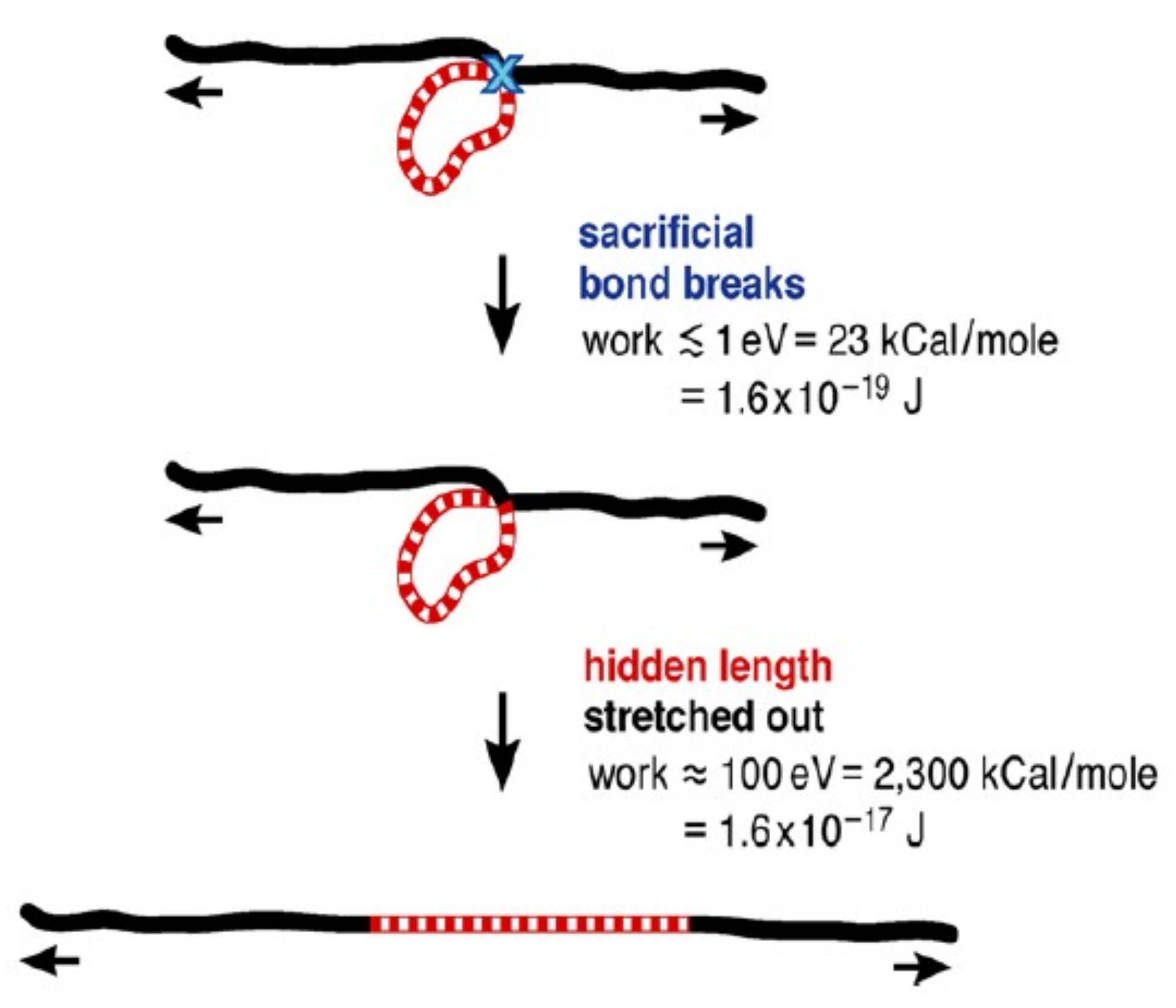
2.1. Biomechanism

The new isolation system is inspired by the biomechanism of an abalone shell. An abalone shell is mainly made up of Calcium carbonate and organic matter. The proportion of organic matter is less than 3%, but it makes a significant contribution to the macroscopic mechanism of an abalone shell [30,31]. The highly-ordered crystal composite is about 3000 times stronger than general Calcium carbonate crystal, due to the minor amount of organic matter in an abalone shell [32,33].
There exists a kind of special colloform containing a biomechanism named “sacrificial bonds and hidden length” in the organic matter of an abalone shell. The special colloform makes it possible for an abalone shell to maintain its excellent mechanical properties, and the colloform may be stretched from 1 nm to 100 nm or even more [31]. The mechanical principle is illustrated in Figure 1 [28].
It can be seen from Figure 1 that resistance entropy will come into being gradually when the molecule is stretched. The sacrificial bonds will be broken while the energy accumulates to about 1 eV, followed by the release of a hidden length (zebra stripes as Figure 1 shows). In the following progression of stretching, the solid black part and the zebra stripes part will work cooperatively until the dissipative energy reaches 100 eV or so. The key point of the mechanism is that the process is reversible and the “sacrificial bonds” can be rebuilt after the tension is released and work again in the next cycle. In the process of restoring, the molecule will reserve a “hidden length” and lock it to avoid the occurrence of internal force. In consideration of the excellent capability of dissipating energy, researchers have tried to apply it on vibration isolators to realize a superior effect.

2.2. Restoring Force Model

By simulating the biomechanism of “sacrificial bonds and hidden length” of an abalone shell, the new isolation system behaves in a way that the isolator only provides resistance B I O ( x , x ˙ ) while restoring it to the equilibrium position. The specific expression of B I O ( x , x ˙ ) is shown in Formula (2). The total restoring force of the bio-inspired isolator is shown in Formula (1).
f B I O = k b x + c b x ˙ + B I O ( x , x ˙ )
B I O ( x , x ˙ ) = { f max i f x 0 a n d x ˙ 0 f max i f x < 0 a n d x ˙ > 0 0 i f x x ˙ > 0
where x and x ˙ are the horizontal displacement and horizontal velocity of the isolator, respectively; k b is the stiffness; c b is the damping coefficient; and B I O ( x , x ˙ ) is the BIO force. The bio-inspired element consists of a linear spring element, a linear damping element, and a BIO element, all connected in parallel, as is illustrated in Figure 2. In the vertical direction, the mechanistic property can be simplified as a linear spring for which the axis stiffness is very large.
The BIO element dissipates energy only in the process of returning to the equilibrium position and makes no contribution to the process of vibrating away from the equilibrium position.

3. Development of User Subroutine

3.1. Secondary Development in Abaqus

Abaqus/Standard has an interface that allows users to implement linear and nonlinear finite elements. The interface makes it possible to define any element of arbitrary complexity. It is a versatile analysis tool with a large element library that allows analysis of the most complex structural problems. The advantages of implementing user elements in an analysis code such as Abaqus, instead of writing a complete analysis code, are obvious:
(1)
Abaqus offers a large selection of structural elements, analysis procedures, and modeling tools;
(2)
Abaqus offers preprocessing and postprocessing. Many third-party vendors offer preprocessing and postprocessors with interfaces for Abaqus;
(3)
Maintaining and porting subroutines is much easier than maintaining and porting a complete finite element program.
Secondary development of the bio-inspired isolation system is based on the UEL interface. A diagram of the bio-inspired isolation element is shown as Figure 3. This user subroutine consists of two nodes, for which each has 6 degrees of freedom. Three degrees need to be assigned proper parameters, while boundary conditions in the other three rotational degrees of freedom are assigned as fixed by default. The local coordinate system of the user subroutine is made up of axis 1, axis 2, and axis 3. Axis 1 represents the axial direction, and axis 2 and axis 3 represent two transverse directions of freedom.
The user must define rhs, amatrx, and svars in the UEL interface. The full name of rhs is the right-hand-side vector, which means the contribution to the global system of the user element. amatrx is an array containing the contribution of this element to the Jacobian(stiffness) or other matrix of the overall system of equations.
The matrix required at any time depends on the entries in the lflags array. The Jacobian should include all direct and indirect dependencies of flux and deformation at the node. A more accurately defined Jacobian can improve convergence in general steps. The Jacobian can be symmetric or nonsymmetric. All nonzero entries in amatrx should be defined, even if the matrix is symmetric. svars means an array containing the values of the solution-dependent state variables associated with this element. For the general nonlinear analysis step, the vector svars contains the value of variables in both the current step and last step. svars provides the theoretical basis of the auto incrementation direct integration method, and makes it capable of monitoring the convergence of the dynamic analysis step, adjusting the time incrementation correspondingly. The props array in the UEL interface consists of parameters of the real isolator which must be defined in the user subroutine, and works as the link between the user subroutine and the main program. The properties of the bio-inspired user subroutine are listed in Table 1. To simplify the analysis and be close to reality, the properties in both the transverse directions are defined in the same way.
The flow path of calling the user subroutine in Abaqus is shown as Figure 4. In each incrementation step of direct time history analysis, the main program passes the information of nodes (including displacement and velocity) to UEL, and calculates the internal forces based on the restoring force model defined by the user. Following this, the node forces are updated and the variables are stored, and the UEL subroutine then exits the current incrementation and the main program moves forward to the next incrementation.

3.2. Simulation in SAP2000

The bio-inspired mechanism can also be achieved by the combination of link elements in SAP2000. The hysteresis curve is shown in Figure 5c. It can be seen from Figure 5 that the first quadrant and the third quadrant of the Multi-Linear elastic link and the Plastic Wen link will counteract to zero, while the second quadrant and the forth quadrant double.

4. Verification of User Subroutine

The user subroutine can be applied to realistic research or design only after being rigorously verified. The lumped mass model or simplified 3D model is relatively well-executed and superior to the complex 3D model in computational precision verifying for introducing less uncertainty. Reference software is the commonly used analysis program SAP2000 and Simulink toolbox of Matlab.

4.1. Verification of Restoring Force Model

Elastic restoring force, damping force, and BIO force can be extracted from the lumped mass model subject to sinusoidal displacement excitation at the mass joint. It can be concluded from Figure 6 that the restoring force model is identical to that of the theoretical curve in the outline. More specified details should be verified further in delicate analysis.

4.2. Verification of Bio-Inspired Isolator User Subroutine in Lumped Mass Model

The bio-inspired isolation system is applied in a 2DOF lumped mass model in this chapter. The diagram of the structural model is exhibited in Figure 7. There are two mass points in the model, representing the isolation layer and the superstructure, respectively.
Structural mechanical parameters consist of isolator mass mb, stiffness of isolation layer kb, damping coefficient of isolation layer cb, BIO force of isolation layer fbio, mass of superstructure ms, stiffness of superstructure ks, and damping coefficient of superstructure cs. The concrete value of each parameter is shown in Figure 7. Kobe motion, of which the PGA has been tuned to 0.1 g, is applied to the model. The value of BIO force is determined by the differential evolution optimization algorithm and is finally set to 3096 kN. In practical design, BIO force can be simply set to 1~4% of the self-weight of the structure to avoid a complex and time-consuming calculation of optimizing. A comparison of user subroutines of Abaqus, SAP2000, and Matlab/Simulink is shown in Figure 8 and Table 2.
The unique restoring force model of the bio-inspired isolation system can also be pieced together by the parallel of the Plastic Wen link element and Multilinear elastic link element in SAP2000. The restoring force model of the above-motioned element can be shown in Figure 5. Figure 5a illustrates the restoring force model of the Multilinear elastic link and Figure 5b illustrates the restoring force model of the Plastic Wen link element. Figure 5c is the same shape as the theoretical BIO element.
The nonlinear direct integration method HHT is adopted in the simulation of SAP2000. The iteration control parameter is defined as the same as that of Abaqus. The comparison of the computational accuracy of dynamic analysis by Abaqus, SAP2000, and Matlab/Simulink is shown in Figure 8.
It can be inferred from Table 2 that the relative accuracy error in Abaqus can be controlled in the range of 3%, compared to the dynamic output in SAP2000 and Matlab/Simulink toolbox.

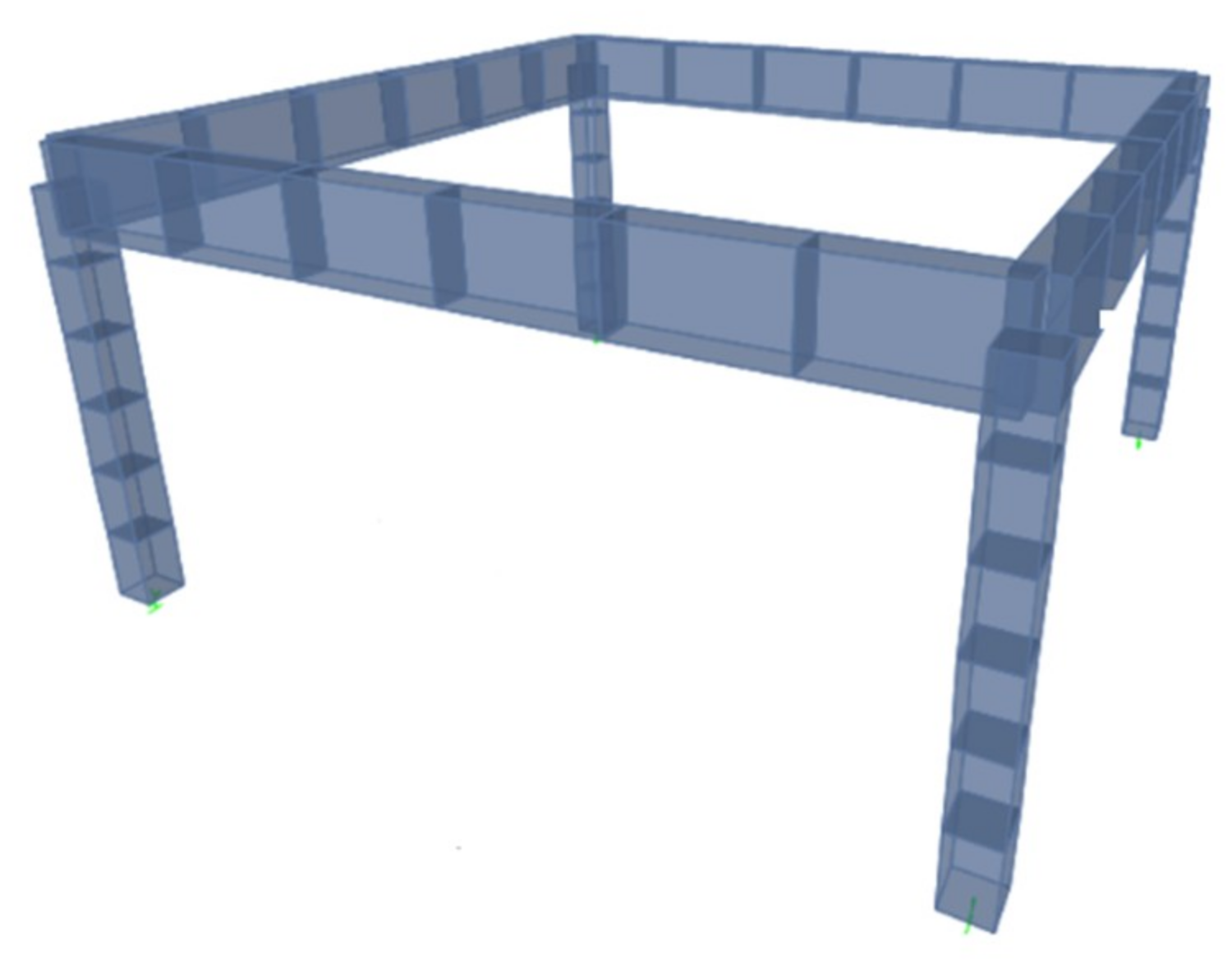
4.3. Verification of 3D Simple Model

Computational accuracy verification in a simple 3D model can be conducted in the following ways: (1) Set the numerical value of fbio to be equal to zero, degenerating the user subroutine to a regular spring and damper element; and (2) rebuild the structure in SAP2000 with the same parameters. The basic parameters are illustrated in Table 3. The 3D view of the model is shown in Figure 9. In Abaqus/Standard, the spring element and dashpot element of joints can be used to simulate the property of the linear spring and linear damper. The Connector library can also achieve the same result by defining the linear stiffness and linear damping coefficient. The UEL will degenerate to a regular linear isolator by assigning a value of zero to fbio. It can be noted from Figure 10 that the bio-inspired user subroutine can reach almost the same computational precision as the built-in elements in Abaqus.
The structural model was built in SAP2000 with the same materials and the same dimensions. The direct time history analysis was then run and the results obtained are shown as Figure 11. Detailed comparative results are shown in Table 4. It can be revealed from these results that the relative error between the UEL subroutine and SAP2000 is less than 2%, and the maximum relative error is only 1.5%.
It can be concluded from the above-mentioned development and verification that the UEL subroutine can satisfy the need of scientific calculation and structural design. What is more, the UEL can expand the research on the bio-inspired isolation system from the simplified lumped mass model to a real complicated 3D model, and can thus carry the study forward.

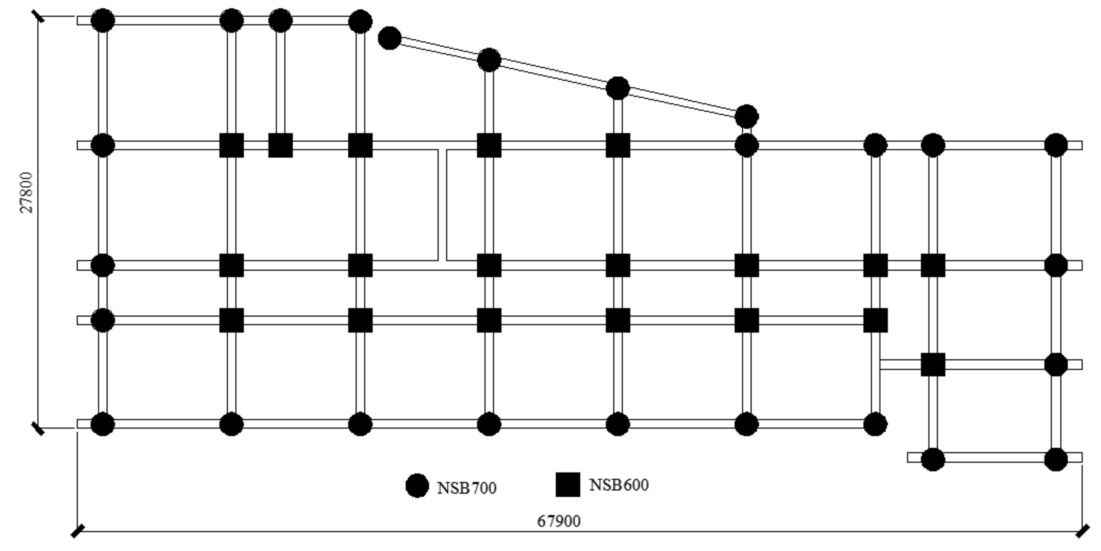
5. Verification of 3D Complex Structural Model

Control Algorithm

The UEL subroutine of the bio-inspired isolation system is used in the real 3D structural model to demonstrate the relative advantage compared to the traditional linear isolation system. Take a teaching building of a certain primary school as an example, where the linear vibration isolation system is applied in this model in contrast to the bio-inspired isolation system. To make it comparable, the stiffness and damping coefficient of the bio-inspire isolation system and linear isolation system should be kept the same.
The teaching building is a frame structure with a total of four floors and an altitude of 14.4 m. At the view of the plane figure, the structure is 64.4 m in the EW direction and 27.2 m in the NS direction. The 3D view is shown in Figure 12. The local seismic fortification intensity is 8 degrees, with a PGA of 0.2 g. The site classification for construction belongs to class II and the third group.
The selection of strong motion records for nonlinear dynamic analysis is not a straightforward process. Subjected to the excitation of near-fault long-periodic pulsed seismic motion, the displacement of the isolated layer of the structure is more likely to be much larger than the structure under regular seismic motion. Bio-inspired isolation bearing can simultaneously reduce the displacement of the isolation layer and the acceleration response of the superstructure. Twenty-eight near-fault seismic waves with the same PGA of 0.4 g are selected in this part to be applied to the teaching building to study its response under rare earthquakes.
The information of 28 seismic motions is shown in Table 5. All selected seismic waves are near-fault pulsed seismic waves with an epicenter distance of 10 km or less.
The parameters of the isolators are shown in Table 6. The traditional linear isolation system adopts the combination of LRB700 and LNR600, while the bio-inspired isolation system employs the combination of NSB700 and LNR600, of which NSB take the place of LRB700. The NSB isolator has one more parameter to express the BIO force than the LRB isolator. The total peak value of the BIO force in the isolation layer occupies approximately 1% of the self-weight of the upper structure. Each NSB700 isolator contributes a value of 37.9 KN.
The plane layout of isolation bearing is shown in Figure 13. NSB700 should always be arranged as close as possible to the edges of the structure to be conducive to the eccentricity and enhance the torsional capacity, since NSB can provide a larger restoring force than LNR like LRB.
A dynamic response of the bio-inspired isolation system and linear isolation system can be obtained by direct time history analysis. To evaluate the effect of the bio-inspired isolation system superior to the linear isolation system, a reducing rate is introduced. The reducing rate is defined as (RBIOR)/R, of which RBIO and R represent the response of the bio-inspired isolation system and linear isolation system, respectively. The reducing rate of base displacement, acceleration of the superstructure, and interlaminar shear force are shown as Figure 14, Figure 15 and Figure 16.
The displacement of the bio-inspired isolation layer is at most 44.5% and on average, 20.4% less than that of the linear isolation system under the excitation of the seismic wave in the X-direction.
In the Y direction, as a result of the larger height-width ratio of the building, the acceleration responses in the upper structure of the bio-inspired isolation system are larger than those of the linear isolation system.
Figure 15 shows the interlaminar shear force reducing ratio of the superstructure of the bio-inspired isolated system relative to the linear isolation system.
In the X direction, the maximum reduction ratios are 32.8%, 37.9%, 37.9%, and 38.4%, respectively, and the average reduction ratios are 12%, 13.8%, 16.5%, and 20%, respectively. In the Y direction, the shear forces of the bio-inspired isolation system in floor I and floor II are smaller than those of the linear isolation system and are much larger in floor III and floor IV. The possible reason for this is that the aspect ratio in the Y direction is relatively larger than that in the X direction. Shear forces in floor I and floor II are more liable to be controlled since the isolation layer is much closer to floor I and floor II. These results show that the bio-inspired isolation system may be sensitive to the aspect ratio. In the process of designing the system, it is necessary to take more consideration of the applicability.
According to the Seismic design code for Buildings in China, the shear force of the isolated model should be less than 40% of the shear force of the non-isolated model. As for the bio-inspired model in this case, the shear force ratio in the X and Y direction is 0.234 and 0.285, which means that the shear force is still acceptable.
The bio-inspired isolated structure performs much better than the traditional linear isolated structure in the acceleration of the superstructure in both the X direction and Y direction. In the X direction, base displacement of the bio-inspired isolated structure is, at most, 21.6% less than that of the traditional linear isolated structure under certain seismic waves. The mean reducing ratio reaches 5.1%. In the Y direction, base displacement of the bio-inspired isolated structure is, at most, 34.7% less and 7.1% on average.

6. Conclusions

Under the excitation of the near-fault pulsed seismic wave which contains a significant long-term displacement pulse or velocity pulse, the isolation layer may tend to be destroyed as a result of excessive base displacement and lead to the loss of protection of the superstructure. The new bio-inspired isolation system proposed by Dr X Chen seems to be a nice try at controlling the base displacement of the isolation layer and acceleration of superstructure simultaneously. By means of the open application program interface of Abaqus, this paper develops a new user subroutine to simulate the unique hysteresis property of the bio-inspired isolation system and extend the current study from the simplified lumped mass model to the real complex 3D structural model. In summary, it can be inferred that:
(1)
In the lumped mass model, the restoring force model of the user subroutine is verified by comparing it to the theoretical restoring force model under sinusoidal load;
(2)
It can be concluded from the comparison of the UEL subroutine in Abaqus and Matlab/Simulink or SAP2000 that the user subroutine can meet the demand of scientific research in the lumped mass model;
(3)
By comparing the response of the structure with the UEL subroutine, joint/connector, and SAP2000, the user subroutine can reach a satisfying computational accuracy in the 3D model;
(4)
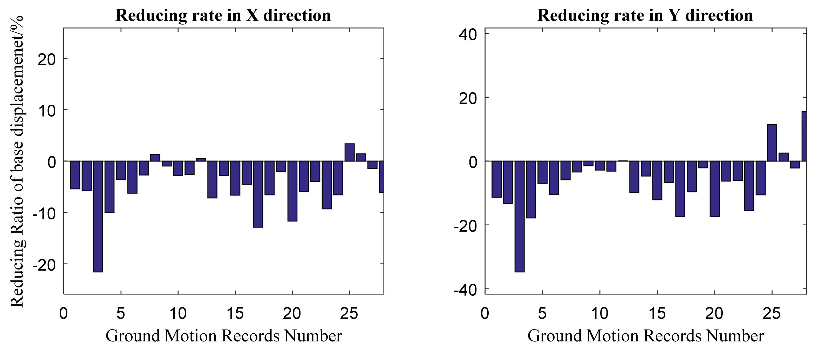
The user subroutine can be applied in the real complex 3D structural model to simulate the bio-inspired isolation system. In the case study, the bio-inspired isolation system performs much better in the X direction than the traditional isolated system. In the Y direction, compared to the response of the traditional isolated system, the base displacement and the shear force of floor I and floor II (response below floor II) are smaller, while the acceleration at the top story and shear force of floor III and floor IV (response above floor III) are larger. It can be concluded that the bio-inspired isolated system is sensitive to the aspect ratio of the structure and will perform differently in two directions. Despite this, the response of low floors will always benefit from the bio-inspired system. The response of the high floors may be larger than that of traditional isolated results, but is still acceptable.
By proper design, the new bio-inspired isolation system can reach better control among the displacement of the isolation layer, acceleration at the top story, and interlaminar shear force at the same time. It is also noted that the bio-inspired isolation system is much more sensitive to the aspect ratio, and more exact design and analysis should be done to apply it to real projects.

Author Contributions

Q.Z. carried out the numerical simulations and wrote the paper. W.S. and J.S. proposed the idea. J.S. and Z.S. provided valuable discussions and revised the paper.

Funding

National Natural Science Foundation of China: 51408435.

Acknowledgments

This project was supported as a project of the National Natural Science Foundation of China (Grant No. 51408435).

Conflicts of Interest

The authors declare no conflict of interest.

References

  1. Shi, W.; Wang, L.; Lu, Z. Study on self-adjustable tuned mass damper with variable mass. Struct. Control Health Monit. 2017, 25, e2114. [Google Scholar] [CrossRef]
  2. Shi, W.; Wang, L.; Lu, Z.; Gao, H. Study on adaptive-passive and semi-active eddy current tuned mass damper with variable damping. Sustainability 2018, 10, 99. [Google Scholar] [CrossRef]
  3. Shi, W.; Wang, L.; Lu, Z.; Zhang, Q. Application of an artificial fish swarm algorithm in an optimum tuned mass damper design for a pedestrian bridge. Appl. Sci. 2018, 8, 175. [Google Scholar] [CrossRef]
  4. Wang, L.; Shi, W.; Zhou, Y. Study on self-adjustable variable pendulum tuned mass damper. Struct. Des. Tall Spec. Build. 2018, e1561. [Google Scholar] [CrossRef]
  5. Cancellara, D.; De Angelis, F. Assessment and dynamic nonlinear analysis of different base isolation systems for a multi-storey RC building irregular in plan. Comput. Struct. 2017, 180, 74–88. [Google Scholar] [CrossRef]
  6. Lewandowski, R.; Łasecka-Plura, M. Design sensitivity analysis of structures with viscoelastic dampers. Comput. Struct. 2016, 164, 95–107. [Google Scholar] [CrossRef]
  7. Kvåle, K.; Sigbjörnsson, R.; Øiseth, O. Modelling the stochastic dynamic behavior of a pontoon bridge: A case study. Comput. Struct. 2016, 165, 123–135. [Google Scholar] [CrossRef]
  8. Lee, T.; Kawashima, K. Semi-active control of nonlinear isolated bridges with time delay. J. Struct. Eng. 2007, 133, 235–241. [Google Scholar] [CrossRef]
  9. Sayani, P.; Ryan, K. Comparative evaluation of base-isolated and fixed-base buildings using a comprehensive response index. J. Struct. Eng. 2009, 135, 698–707. [Google Scholar] [CrossRef]
  10. Hu, J. Response of Seismically Isolated Steel Frame Buildings with Sustainable Lead-Rubber Bearing (LRB) Isolator Devices Subjected to Near-Fault (NF) Ground Motions. Sustainability 2014, 7, 111–137. [Google Scholar] [CrossRef] [Green Version]
  11. Halldórsson, B.; Mavroeidis, G.; Papageorgiou, A. Near-fault and far-field strong ground-motion simulation for earthquake engineering applications using the specific barrier model. J. Struct. Eng. 2010, 137, 433–444. [Google Scholar] [CrossRef]
  12. Foti, D. Local ground effects in near-field and far-field areas on seismically protected buildings. Soil Dyn. Earthq. Eng. 2015, 74, 14–24. [Google Scholar] [CrossRef]
  13. Tirca, L.D.; Foti, D.; Diaferio, M. Response of middle-rise steel frames with and without passive dampers to near-field ground motions. Eng. Struct. 2003, 25, 169–179. [Google Scholar] [CrossRef]
  14. Foti, D. On the Seismic Response of Protected and Unprotected Middle-Rise Steel Frames in Far-Field and Near-Field Areas. Shock Vib. 2014, 2014, 393870. [Google Scholar] [CrossRef]
  15. Buratti, N.; Stafford, P.; Bommer, J. Earthquake accelerogram selection and scaling procedures for estimating the distribution of drift response. J. Struct. Eng. 2010, 137, 345–357. [Google Scholar] [CrossRef]
  16. Kalpakidis, I.; Constantinou, M.; Whittaker, A.S. Effects of large cumulative travel on the behavior of lead-rubber seismic isolation bearings. J. Struct. Eng. 2009, 136, 491–501. [Google Scholar] [CrossRef]
  17. Symans, M.; Constantinou, M. Semi-active control systems for seismic protection of structures: A state-of-the-art review. Eng. Struct. 1999, 21, 469–487. [Google Scholar] [CrossRef]
  18. Bitaraf, M.; Ozbulut, O.E.; Hurlebaus, S.; Barroso, L. Application of semi-active control strategies for seismic protection of buildings with MR dampers. Eng. Struct. 2010, 32, 3040–3047. [Google Scholar] [CrossRef]
  19. Kannan, S.; Uras, H.; Aktan, H. Active control of building seismic response by energy dissipation. Earthq. Eng. Struct. Dyn. 2010, 24, 747–759. [Google Scholar] [CrossRef]
  20. Rodellar, J.; Barbat, A. Active control of building structures under measured seismic loads. Eng. Comput. 2018, 2, 128–134. [Google Scholar] [CrossRef]
  21. Nguyen, X.B.; Komatsuzaki, T.; Iwata, Y.; Asanuma, H. Modeling and semi-active fuzzy control of magnetorheological elastomer-based isolator for seismic response reduction. Mech. Syst. Signal Process. 2018, 101, 449–466. [Google Scholar] [CrossRef]
  22. Zhao, D.; Li, Y.; Li, H.; Qian, H. Seismic reductions investigation of semi-active base-isolated structure based on multi-level fuzzy control. Shock Vib. 2016, 35, 78–84. [Google Scholar]
  23. Cha, Y.; Agrawal, A. Seismic retrofit of MRF buildings using decentralized semi-active control for multi-target performances. Earthq. Eng. Struct. Dyn. 2017, 46, 409–424. [Google Scholar] [CrossRef]
  24. Kappos, A.; Gkatzogias, K. Semi-Active Control Systems in Bridge Engineering: A Review of the Current State of Practice. Struct. Eng. Int. 2016, 26, 290–300. [Google Scholar] [Green Version]
  25. Yang, J.N.; Wu, J.C.; Kawashima, K.; Unjoh, S. Hybrid control of seismic-excited bridge structure. Earthq. Eng. Struct. Dyn. 2010, 24, 1437–1451. [Google Scholar] [CrossRef]
  26. Park, K.; Jung, H.; Lee, I. Hybrid control strategy for seismic protection of a benchmark cable-stayed bridge. Eng. Struct. 2003, 25, 405–417. [Google Scholar] [CrossRef]
  27. Yang, H.T.Y.; Lin C-Hung Bridges, D.; Randall, C.J.; Hansma, P.K. Bio-inspired passive actuator simulating an abalone shell mechanism for structural control. Smart Mater. Struct. 2010, 19, 105011. [Google Scholar] [CrossRef]
  28. Chen, X.; Yang, H.T.Y.; Shan, J.; Hansma, P.K.; Shi, W. Bio-Inspired Passive Optimized Base-Isolation System for Seismic Mitigation of Building Structures. J. Eng. Mech. 2015, 142, 04015061. [Google Scholar] [CrossRef]
  29. Shan, J.; Shi, Z.; Hu, F.; Yu, J.; Shi, W. Stochastic optimal design of novel nonlinear base isolation system for seismic-excited building structures. Struct. Control Health Monit. 2016, 25, e2168. [Google Scholar] [CrossRef]
  30. Thurner, P.J.; Erickson, B.; Jungmann, R.; Schriock, Z.; Weaver, J.C.; Fantner, G.E.; Schitter, G.; Morse, D.E.; Hansma, P.K. High-speed photography of compressed human trabecular bone correlates whitening to microscopic damage. Eng. Fract. Mech. 2007, 74, 1928–1941. [Google Scholar] [CrossRef]
  31. Hansma, P.K.; Fantner, G.E.; Kindt, J.H.; Thurner, P.J.; Schitter, G.; Turner, P.J.; Udwin, S.F.; Finch, M.M. Sacrificial bonds in the interfibrillar matrix of bone. J. Musculoskelet. Neuronal Interact. 2005, 5, 313. [Google Scholar] [PubMed]
  32. Fantner, G.E.; Oroudjev, E.; Schitter, G.; Golde, L.S.; Thurner, P.; Finch, M.M.; Turner, P.; Gutsmann, T.; Morse, D.E.; Hansma, H.; et al. Sacrificial bonds and hidden length: Unraveling molecular mesostructures in tough materials. Biophys. J. 2006, 90, 1411–1418. [Google Scholar] [CrossRef] [PubMed]
  33. Becker, N.; Oroudjev, E.; Mutz, S.; Cleveland, J.P.; Hansma, P.K.; Hayashi, C.Y.; Makarov, D.E.; Hansma, H.G. Molecular nanosprings in spider capture-silk threads. Nat. Mater. 2003, 2, 278–283. [Google Scholar] [CrossRef] [PubMed]
Figure 1. Mechanism of “sacrificial bonds and hidden length” [26].
Sustainability 11 00278 g001
Figure 2. The mechanical model of bio-inspired isolation system.
Sustainability 11 00278 g002
Figure 3. Restoring force curve of BIO isolation system.
Sustainability 11 00278 g003
Figure 4. The flow of secondary development of user subroutine.
Sustainability 11 00278 g004
Figure 5. The combination of restoring force of link elements in SAP2000.
Sustainability 11 00278 g005
Figure 6. Restoring force model of bio-inspired isolation system.
Sustainability 11 00278 g006
Figure 7. Diagram of 2DOF Model.
Sustainability 11 00278 g007
Figure 8. Response and restoring force of bio-inspired system. (a) Response of 2DOF model in Abaqus/SAP2000/Simulink; (b) Comparison of restoring force in SAP2000/Abaqus.
Sustainability 11 00278 g008
Figure 9. Diagram of 3D model.
Sustainability 11 00278 g009
Figure 10. The results of user subroutine and built-in elements in Abaqus.
Sustainability 11 00278 g010
Figure 11. Response and restoring force of bio-inspired element. (a) Response of bio-inspired isolation system; (b) Restoring force of BIO element.
Sustainability 11 00278 g011
Figure 12. 3D view of a teaching building.
Sustainability 11 00278 g012
Figure 13. Plane layout of isolation bearings.
Sustainability 11 00278 g013
Figure 14. Reducing rate of acceleration of superstructure in X and Y direction.
Sustainability 11 00278 g014
Figure 15. Reducing rate of interlaminar shear force in X and Y direction.
Sustainability 11 00278 g015
Figure 16. Reducing rate of base displacement in X and Y direction.
Sustainability 11 00278 g016
Table 1. The definition of parameters of bio-inspired isolation system.
UEL Parameters Variable NameMeaningUnits
props (1)KhHorizontal shear stiffnessN/m
props (2)KvVertical pression stiffnessN/m
props (3)ChHorizontal damping coefficientN/(m/s)
props (4)MMass of isolatorkg
props (5)FBIOHorizontal BIO forceN
Table 2. The comparison of computational accuracy of dynamic analysis of lumped mass model.
Evaluation IndexUnitAbaqusSimulink (Error)SAP2000 (Error)
dbmaxm0.02090.0213 (−1.9%)0.0216 (−3.2%)
asmaxm/s20.18480.1751 (5.5%)0.1883 (−1.9%)
FmaxN56325683 (−0.9%)5742 (−1.9%)
FbiomaxN30973096 (0%)3097 (0%)
FemaxN56485683 (−0.6%)5742 (−1.6%)
Table 3. Parameters of 3D model.
ParameterUnitValue
Material C30
Section of Beammm250 × 600
Section of Columnmm200 × 200
Spanm6
Heightm3
Table 4. The comparison of Abaqus and SAP2000.
Evaluation IndexUnitsAbaqusSAP2000Relative Error/%
dbmaxm0.13930.1395−0.1
asmaxm/s21.48701.5097−1.5
FmaxN37443779−0.9
FbiomaxN401.02400−0.3
FemaxN37703779−0.2
Table 5. Information of near-fault pulsed seismic wave.
NGA#WaveYearTypeR_jb [km]R_rup [km]
181H-E061401979Strike-Slip01.4
181H-E062301979Strike-Slip01.4
182H-E071401979Strike-Slip0.60.6
182H-E072301979Strike-Slip0.60.6
292A-STU0001980Normal6.810.8
292A-STU2701980Normal6.810.8
723B-PTS2251987Strike-Slip0.90.9
723B-PTS3151987Strike-Slip0.90.9
802STG0001989Reverse-Oblique7.68.5
802STG0901989Reverse-Oblique7.68.5
821ERZ-EW1992Strike-Slip04.4
821ERZ-NS1992Strike-Slip04.4
828PET0001992Reverse08.2
828PET0901992Reverse08.2
879LCN2601992Strike-Slip2.22.2
879LCN3451992Strike-Slip2.22.2
1063RRS2281994Reverse06.5
1063RRS3181994Reverse06.5
1086SYL0901994Reverse1.75.3
1086SYL3601994Reverse1.75.3
1165IZT0901999Strike-Slip3.67.2
1165IZT1801999Strike-Slip3.67.2
1503TCU065-E1999Reverse-Oblique0.60.6
1503TCU065-N1999Reverse-Oblique0.60.6
1529TCU102-E1999Reverse-Oblique1.51.5
1529TCU102-N1999Reverse-Oblique1.51.5
1605DZC1801999Strike-Slip06.6
1605DZC2701999Strike-Slip06.6
Table 6. Parameters of isolation layer.
ParametersUnitLRB700 (NSB700)LNR600
External diametermm700600
Vertical stiffnesskN/mm18581526
Equivalent stiffness (γ = 1)kN/mm2.2081.103
Equivalent damping index (γ = 1)--0.120
Equivalent damping coefficientkN/(m/s)1250
Number--2720

