
Design of a Robust Controller Based on Barrier Function for Vehicle Steer-by-Wire Systems

 ,
,  , , and
Abstract
:1. Introduction
- The development of the ISMC to ensure the minimization of tracking errors in the controlled VSbW system.
- Design of the ISMCbf, which allows the knowledge of lower limit of model uncertainty rather than its upper limit.
- A comparison was made between the proposed control approach and the ISMC strategy based on three main hard scenarios, represented by the slalom path, quick steering, and shock disturbance rejection.
- The control design was devoted to reduce the absolute error to its lower bound.
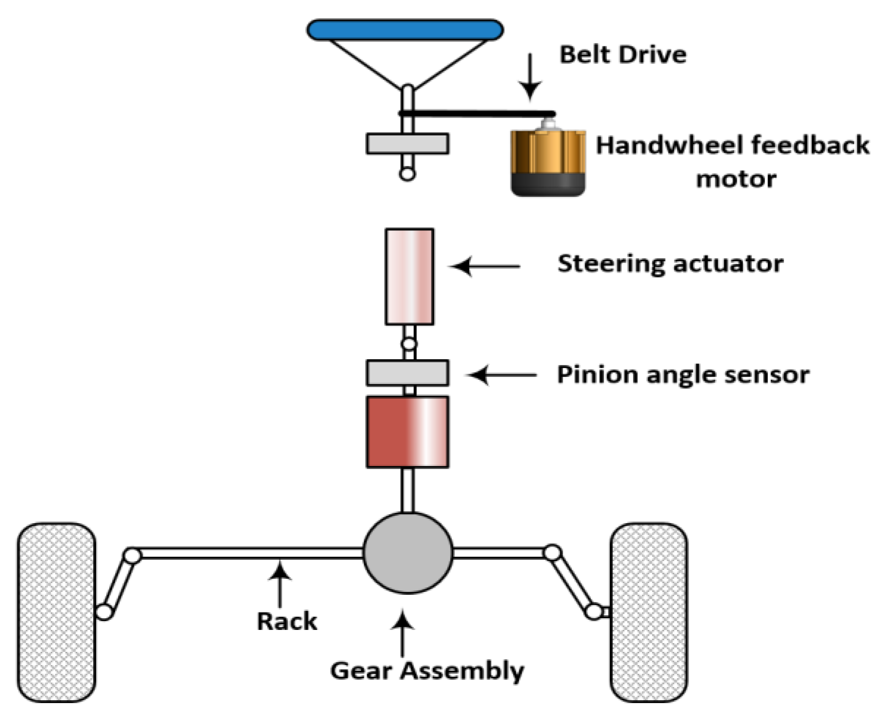
2. Dynamic Model
3. Control Design
3.1. Classical Integral Sliding Mode Control Design for VSbW
3.2. Integral Sliding Mode Controller Design Based on Barrier Function (ISMCbf) for VSbW
- .
- The function has a unique minimum value at zero, such that .
- Positive-definite BFs (PBFs):
- Positive semi-definite BFs (PSBFs):

4. Simulation Results and Discussion
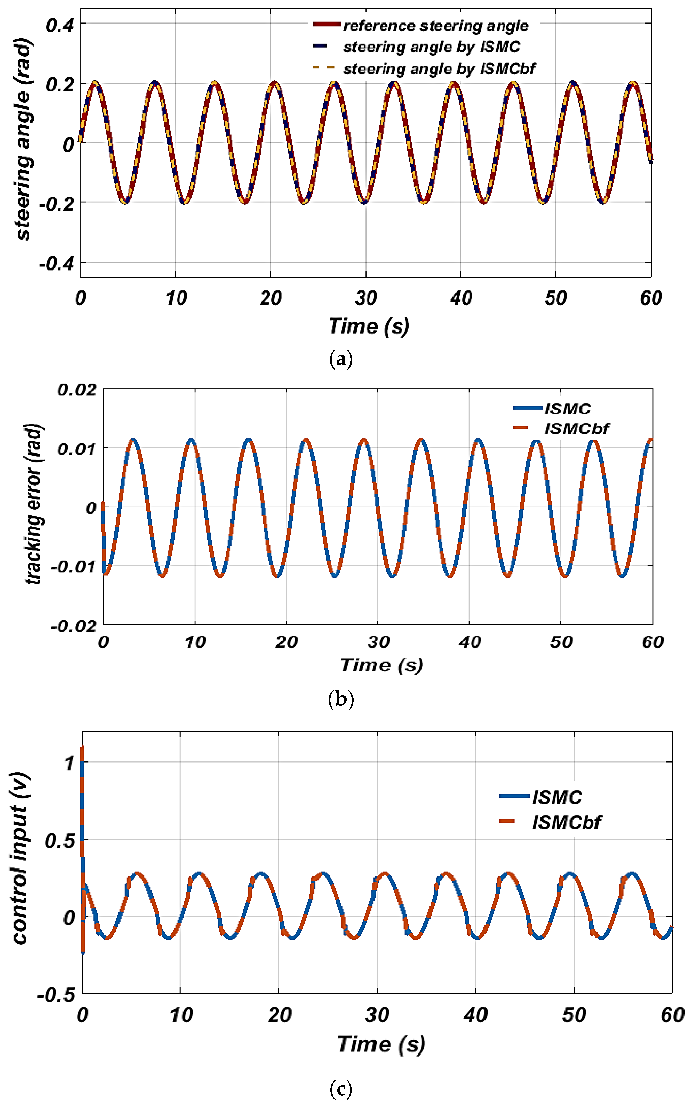
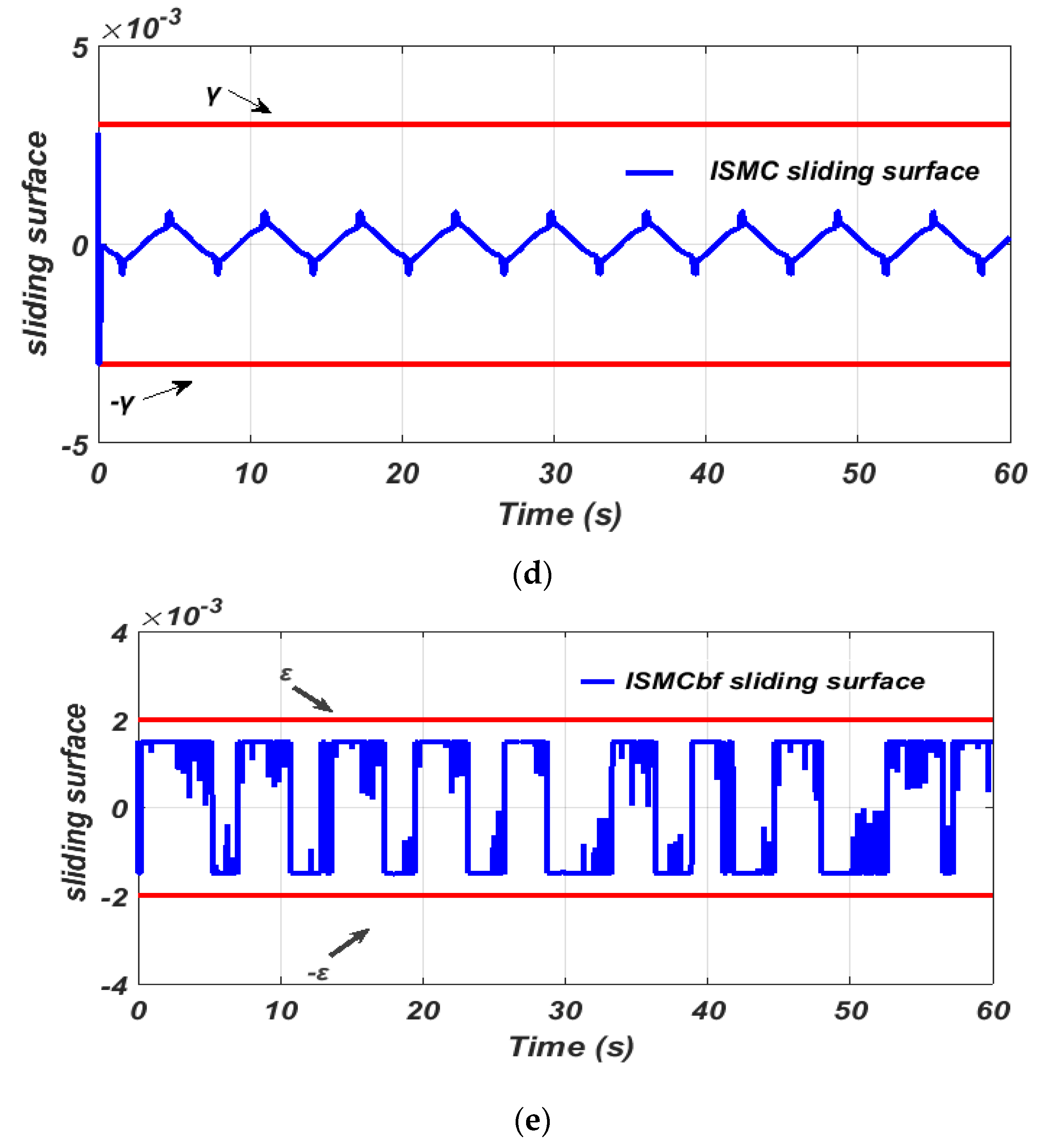
4.1. Slalom Path
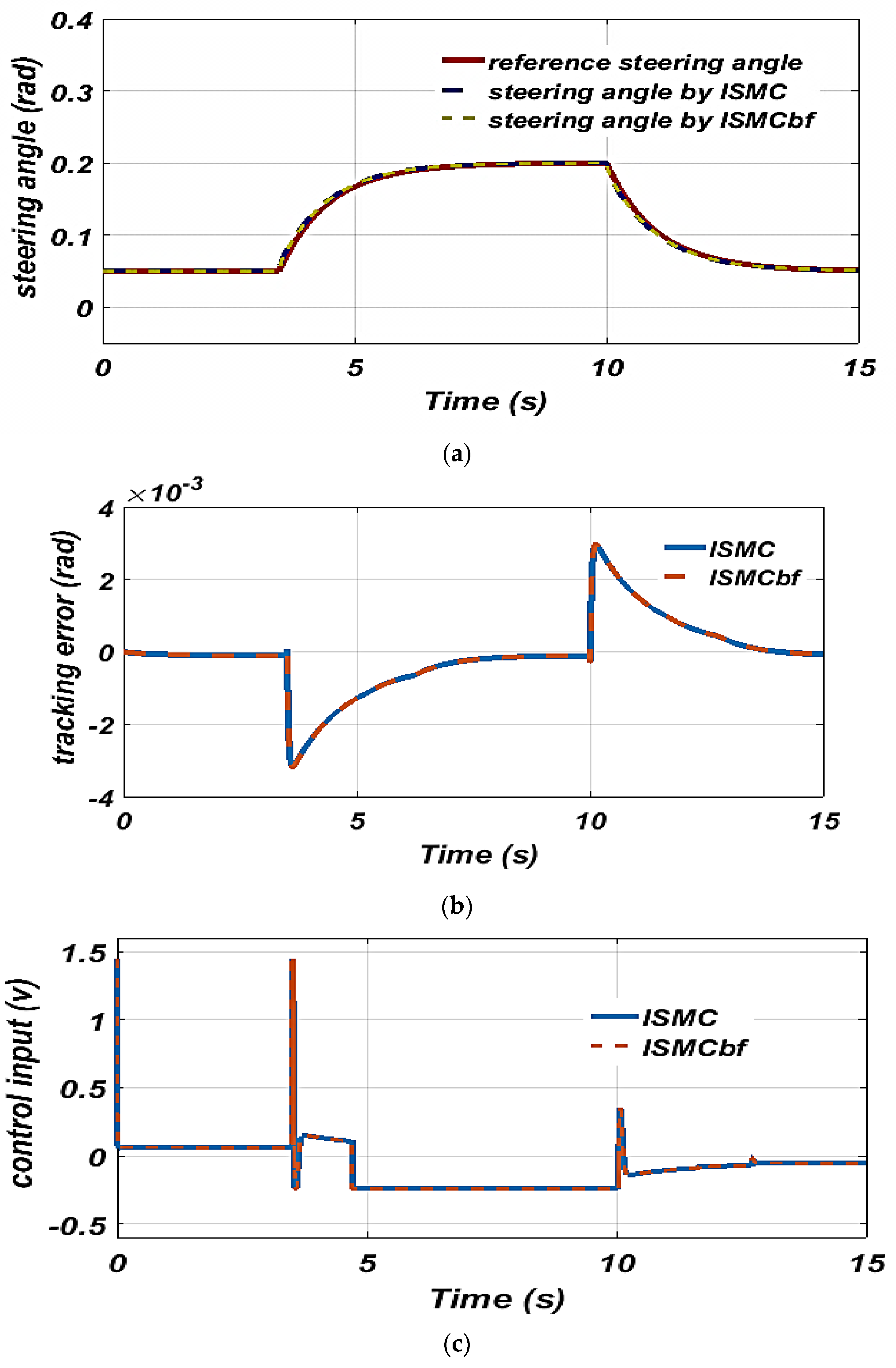
4.2. Quick Steering
4.3. Shock Disturbance Rejection
5. Conclusions
Author Contributions
Funding
Data Availability Statement
Conflicts of Interest
References
- Hoseinnezhad, R.; Bab-Hadiashar, A. Missing data compensation for safety-critical components in a drive-by-wire system. IEEE Trans. Veh. Technol. 2005, 54, 1304–1311. [Google Scholar] [CrossRef]
- Yih, P.; Gerdes, J.C. Modification of vehicle handling characteristics via steer-by-wire. IEEE Trans. Control Syst. Technol. 2005, 13, 965–976. [Google Scholar] [CrossRef]
- Gang, L.; Ning, L.; Guanyi, W.; Gaofeng, M. Study on design method of ideal steering ratios of vehicle steer-by-wire system. In Proceedings of the 2014 International Conference on Mechatronics and Control (ICMC), Jinzhou, China, 3–5 July 2014; pp. 128–131. [Google Scholar]
- Huh, K.; Kim, J. Active steering control based on the estimated tire forces. J. Dyn. Syst. Meas. Control 2001, 123, 505–511. [Google Scholar] [CrossRef]
- Yao, Y. Vehicle Steer-by-Wire System Control (No. 2006-01-1175); SAE Technical Paper; SAE International: Warrendale, PA, USA, 2006. [Google Scholar] [CrossRef]
- Baviskar, A.; Wagner, J.R.; Dawson, D.M.; Braganza, D.; Setlur, P. An adjustable steer-by-wire haptic-interface tracking controller for ground vehicles. IEEE Trans. Veh. Technol. 2008, 58, 546–554. [Google Scholar] [CrossRef]
- Kazemi, R.; Janbakhsh, A.A. Nonlinear adaptive sliding mode control for vehicle handling improvement via steer-by-wire. Int. J. Automot. Technol. 2010, 11, 345–354. [Google Scholar] [CrossRef]
- Qiu, X.Y.; Yu, M.J.; Zhang, Z.L.; Ruan, J.H. Research on steering control and simulation of vehicle Steer-by-Wire system. In Advanced Materials Research; Trans Tech Publications Ltd.: Wollerau, Switzerland, 2012; Volume 403, pp. 5076–5081. [Google Scholar] [CrossRef]
- Zhai, P.; Du, H.; Li, Z. Bilateral control of vehicle Steer-by-Wire system with variable gear-ratio. In Proceedings of the 2013 IEEE 8th Conference on Industrial Electronics and Applications (ICIEA), Melbourne, VIC, Australia, 19–21 June 2013; pp. 811–815. [Google Scholar]
- Sun, Z.; Zheng, J.; Man, Z.; Jin, J. Discrete-time iterative learning control for vehicle steer-by-wire systems. In Proceedings of the 2014 9th IEEE Conference on Industrial Electronics and Applications, Hangzhou, China, 9–11 June 2014; pp. 462–467. [Google Scholar]
- Do, M.T.; Man, Z.; Zhang, C.; Wang, H.; Tay, F.S. Robust sliding mode-based learning control for steer-by-wire systems in modern vehicles. IEEE Trans. Veh. Technol. 2013, 63, 580–590. [Google Scholar] [CrossRef]
- Wang, H.; Man, Z.; Shen, W.; Cao, Z.; Zheng, J.; Jin, J. Robust control for steer-by-wire systems with partially known dynamics. IEEE Trans. Ind. Inform. 2014, 10, 2003–2015. [Google Scholar] [CrossRef]
- Ali, M.; Hunaini, F.; Robandi, I.; Sutantra, N. Optimization of active steering control on vehicle with steer by wire system using Imperialist Competitive Algorithm (ICA). In Proceedings of the 2015 3rd International Conference on Information and Communication Technology (ICoICT), Nusa Dua, Bali, Indonesia, 27–29 May 2015; pp. 500–503. [Google Scholar]
- Sun, Z.; Zheng, J.; Man, Z.; Wang, H. Robust control of a vehicle steer-by-wire system using adaptive sliding mode. IEEE Trans. Ind. Electron. 2015, 63, 2251–2262. [Google Scholar] [CrossRef]
- Sun, Z.; Zheng, J.; Man, Z.; Wang, H.; Lu, R. Sliding mode-based active disturbance rejection control for vehicle steer-by-wire systems. IET Cyber-Phys. Syst. Theory Appl. 2018, 3, 1–10. [Google Scholar] [CrossRef]
- Wang, H.; Man, Z.; Kong, H.; Zhao, Y.; Yu, M.; Cao, Z.; Zheng, J.; Do, M.T. Design and implementation of adaptive terminal sliding-mode control on a steer-by-wire equipped road vehicle. IEEE Trans. Ind. Electron. 2016, 63, 5774–5785. [Google Scholar] [CrossRef]
- Tumari, M.M.; Nasir, M.M.; Saealal, M.S.; Aziz AW, A.; Saat, S.; Suid, M.H.; Ghazali, M.R. The control scheme of vehicle steer by wire system by using PD-PID controller. Proc. Mech. Eng. Res. Day 2017, 2017, 13–14. [Google Scholar]
- Tumari MZ, M.; Saealal, M.S.; Abd Rashid, W.N.; Saat, S.; Nasir MA, M. The vehicle steer by wire control system by implementing PID Controller. J. Telecommun. Electron. Comput. Eng. (JTEC) 2017, 9, 43–47. [Google Scholar]
- Kannan, P.; Natarajan, S.K.; Dash, S.S. Design and Implementation of Fuzzy Logic Controller for Online Computer Controlled Steering System for Navigation of a Teleoperated Agricultural Vehicle. Math. Probl. Eng. 2013, 2013, 590861. [Google Scholar] [CrossRef]
- Tumari MZ, M.; Nasir MA, M.; Saat, S.; Subki AS, R.A.; Rashid WN, A.; Suid, M.H.; Ghazali, M.R. The Control Schemes of Vehicle Steer by Wire System by using Fuzzy Logic and PID Controller. Res. J. Appl. Sci. 2018, 13, 137–145. [Google Scholar]
- Pugi, L.; Favilli, T.; Berzi, L.; Locorotondo, E.; Pierini, M. Brake blending and torque vectoring of road electric vehicles: A flexible approach based on smart torque allocation. Int. J. Electr. Hybrid Veh. (IJEHV) 2020, 12, 87–115. [Google Scholar] [CrossRef]
- Liang, J.; Lu, Y.; Wang, F.; Yin, G.; Zhu, X.; Li, Y. A Robust Dynamic Game-Based Control Framework for Integrated Torque Vectoring and Active Front-Wheel Steering System. IEEE Trans. Intell. Transp. Syst. 2023, 24, 7328–7341. [Google Scholar] [CrossRef]
- Husain, S.S.; MohammadRidha, T. Design of integral sliding mode control for siesmic effect regulation on buildings with unmatched disturbance. Math. Model. Eng. Probl. 2022, 9, 1123–1130. [Google Scholar] [CrossRef]
- Humaidi, A.J.; Hameed, A.H. PMLSM position control based on continuous projection adaptive sliding mode controller. Syst. Sci. Control Eng. 2018, 6, 242–252. [Google Scholar] [CrossRef]
- AL-Samarraie, S.A.; Fateh Midhat, B. Sliding Mode Controller Design for a Crane Container System. Iraqi J. Comput. Commun. Control. Syst. Eng. (IJCCCE) 2014, 14, 58–71. [Google Scholar]
- Pan, Y.; Yang, C.; Pan, L.; Yu, H. Integral sliding mode control: Performance, modification, and improvement. IEEE Trans. Ind. Inform. 2017, 14, 3087–3096. [Google Scholar] [CrossRef]
- Husain, S.S.; MohammadRidha, T. Integral Sliding mode controlled ATMD for buildings under seismic effect. Int. J. Saf. Secur. Eng. 2022, 12, 413–420. [Google Scholar] [CrossRef]
- F Abd, A.; A Al-Samarraie, S. Integral sliding mode control based on barrier function for servo actuator with friction. Eng. Technol. J. 2021, 39, 248–259. [Google Scholar] [CrossRef]
- Husain, S.S.; Kadhim, M.Q.; Al-Obaidi AS, M.; Hasan, A.F.; Humaidi, A.J.; Al Husaeni, D.N. Design of Robust Control for Vehicle Steer-by-Wire System. Indones. J. Sci. Technol. 2023, 8, 197–216. [Google Scholar] [CrossRef]
- Incremona, G.P.; Mirkin, L.; Colaneri, P. Integral Sliding-Mode Control With Internal Model: A Separation. IEEE Control Syst. Lett. 2022, 6, 446–451. [Google Scholar] [CrossRef]
- Hamayun, M.T.; Edwards, C.; Alwi, H. Design and Analysis of an Integral Sliding Mode Fault-Tolerant Control Scheme. IEEE Trans. Autom. Control 2012, 57, 1783–1789. [Google Scholar] [CrossRef]
- Huang, C.; Naghdy, F.; Du, H.; Huang, H. Fault tolerant steer-by-wire systems: An overview. Annu. Rev. Control 2019, 47, 98–111. [Google Scholar] [CrossRef]
- Mortazavizadeh, S.A.; Ghaderi, A.; Ebrahimi, M.; Hajian, M. Recent developments in the vehicle steer-by-wire system. IEEE Trans. Transp. Electrif. 2020, 6, 1226–1235. [Google Scholar] [CrossRef]
- Rasheed, L.T. Performance of the Adaptive Sliding Mode Control Scheme for Output Voltage Control of the DC/DC Buck Converter System. IOP Conf. Ser. Mater. Sci. Eng. 2020, 881, 012118. [Google Scholar] [CrossRef]
- Shanan, D.S.; Kadhim, S.K. Comparative Analysis of Airflow Regulation in Ventilator Systems Using Various Control Strategies. J. Eur. Syst. Autom. 2023, 56, 811–821. [Google Scholar] [CrossRef]
- Utkin, V.; Poznyak, A.; Orlov, Y.V.; Polyakov, A. Road Map for Sliding Mode Control Design; Springer International Publishing: Berlin/Heidelberg, Germany, 2020. [Google Scholar]
- Fridman, L.; Poznyak, A.; Bejarano, F.J. Robust LQ Output Control: Integral Sliding Mode Approach; Springer International Publishing: Berlin/Heidelberg, Germany, 2013. [Google Scholar]
- MohammadRidha, T.; Kadhim, M.Q. A Barrier Function-Based Variable Structure Control for Maglev System. J. Eur. Des Syst. Autom. 2022, 55, 633–639. [Google Scholar] [CrossRef]
- Al-Samarraie, S.A.; Gorial, I.I.; Mshari, M.H. An integral sliding mode control for the magnetic levitation system based on backstepping approach. IOP Conf. Ser. Mater. Sci. Eng. 2020, 881, 012136. [Google Scholar] [CrossRef]
- Obeid, H.; Fridman, L.M.; Laghrouche, S.; Harmouche, M. Barrier function-based adaptive sliding mode control. Automatica 2018, 93, 540–544. [Google Scholar] [CrossRef]
- Armghan, A.; Hassan, M.; Armghan, H.; Yang, M.; Alenezi, F.; Azeem, M.K.; Ali, N. Barrier Function Based Adaptive Sliding Mode Controller for a Hybrid AC/DC Microgrid Involving Multiple Renewables. Appl. Sci. 2021, 11, 8672. [Google Scholar] [CrossRef]
- Abbas, A.; Ahmad, I.; Ahmed, S. Barrier function-based adaptive terminal sliding mode control of plug-in hybrid electric vehicle with saturated control actions. J. Energy Storage 2023, 65, 107254. [Google Scholar] [CrossRef]
- Obeid, H.; Fridman, L.; Laghrouche, S.; Harmouche, M. Barrier Function-Based Adaptive Integral Sliding Mode Control. In Proceedings of the 2018 IEEE Conference on Decision and Control (CDC), Miami, FL, USA, 17–19 December 2018; pp. 5946–5950. [Google Scholar] [CrossRef]
- Yang, P.; Liu, P.; Geng, H.; Jiang, B.; Wen, C. Barrier Function Based Adaptive Global Sliding Mode Fault-tolerant Control of Quad-rotor UAV. Int. J. Control Autom. Syst. 2023, 21, 800–809. [Google Scholar] [CrossRef]
- Humaidi, A.J.; Abdulkareem, A.I. Design of Augmented Nonlinear PD Controller of Delta/Par4-Like Robot. J. Control Sci. Eng. 2019, 2019, 7689673. [Google Scholar] [CrossRef]
- Ahmed, A.S.; Kadhim, S.K. Non-Leaner Control on the Pneumatic Artificial Muscles: A Comparative Study between Adaptive Backstepping and Conventional Backstepping Algorithms. Math. Model. Eng. Probl. 2023, 10, 653–662. [Google Scholar] [CrossRef]
- Humaidi, A.J.; Hameed, A.H. Robustness Enhancement of MRAC Using Modification Techniques for Speed Control of Three Phase Induction Motor. J. Electr. Syst. 2017, 13, 723–741. [Google Scholar]
- Humaidi, A.J.; Kadhim, S.K.; Gataa, A.S. Optimal Adaptive Magnetic Suspension Control of Rotary Impeller for Artificial Heart Pump. Cybern. Syst. 2022, 53, 141–167. [Google Scholar] [CrossRef]
- Liu, W.; He, C.; Ji, Y.; Hou, X.; Zhang, J. Active Disturbance Rejection Control of Path Following Control for Autonomous Ground Vehicles. In Proceedings of the 2020 Chinese Automation Congress (CAC), Shanghai, China, 6–8 November 2020; 2020; pp. 6839–6844. [Google Scholar] [CrossRef]
- Al-Dujaili, A.Q.; Humaidi, A.J.; Allawi, Z.T.; Sadiq, M.E. Earthquake Hazard Mitigation for Uncertain Building Systems Based on Adaptive Synergetic Control. Appl. Syst. Innov. 2023, 6, 34. [Google Scholar] [CrossRef]
- Al-Wais, S.; Al-Samarraie, S.A.; Abdi, H.; Nahavandi, S. Integral Sliding Mode Controller for Trajectory Tracking of A Phantom Omni Robot. In Proceedings of the 2016 International Conference on Cybernetics, Robotics and Control, Hong Kong, China, 19–21 August 2016. [Google Scholar]
- Al-Samarraie, S.A.; Hamzah, M.N.; Al-Nadawi, Y.K. Vehicle ABS control system design via integral sliding mode. Int. J. Autom. Control 2016, 10, 356–374. [Google Scholar] [CrossRef]
- Salman, M.A.; Kadhim, S.K. Optimal backstepping controller design for prosthetic knee joint. J. Eur. Syst. Autom. 2022, 55, 49. [Google Scholar] [CrossRef]
- Ahmed, A.S.; Kadhim, S.K. A Comparative Study Between Convolution and Optimal Backstepping Controller for Single Arm Pneumatic Artificial Muscles. J. Robot. Control 2022, 3, 769–778. [Google Scholar] [CrossRef]
- Rasheed, L.T. An Optimal Modified Elman—PID Neural Controller Design for DC/DC Boost Converter Model. J. Eng. Sci. Technol. 2023, 18, 880–901. [Google Scholar]
- Yousif, N.Q.; Hasan, A.F.; Shallal, A.H.; Humaidi, A.J.; Rasheed, L.T. Performance Improvement of Nonlinear Differentiator Based on Optimization Algorithms. J. Eng. Sci. Technol. 2023, 18, 1696–1712. [Google Scholar]
- Kasim, M.Q.; Hassan, R.F. Active voltage balancing strategy of asymmetric stacked multilevel inverter. Indones. J. Electr. Eng. Comput. Sci. 2021, 23, 665–674. [Google Scholar]
- Mohammed, A.J.; Hassan, R.F. Comparison of Conventional and Modified Direct Torque Control of Three-Phase Induction Motor Using Three-Level Flying Capacitor Inverter. Int. J. Electr. Electron. Eng. Telecommun. 2021, 10, 431–438. [Google Scholar] [CrossRef]
- Hussein, M.A.; Hamza, E.K. Secure Mechanism Applied to Big Data for IIoT by Using Security Event and Information Management System (SIEM). Int. J. Intell. Eng. Syst. 2022, 15, 667–681. [Google Scholar]
- Msallam, M.M.; Samet, R. An Advanced Rivest Cipher 4 Algorithm to Transfer Fast and Secure Data Using Li-Fi Technology. In Proceedings of the 2023 IEEE 13th International Conference on System Engineering and Technology (ICSET), Shah Alam, Malaysia, 2 October 2023; pp. 194–199. [Google Scholar] [CrossRef]


| Parameter | Value |
|---|---|
| [16] | , and 4.2 |
| [16] | 275 |
| [16] | 9, 22, and 0.4 |
| 0.002 | |
| 0.001 | |
| 0.003 |
| Scenario I: Slalom Trajectory | ||
|---|---|---|
| Control Method | Max Tracking Error (Rad) | Max Control Signal (v) |
| ISMC | 0.012 | 1.1 |
| SMC | 0.055 | 1.2 |
| PDADRC | 0.029 | 1.5 |
| ASMC | 0.028 | 1.4 |
| ISMCbf | 0.012 | 1.1 |
| Scenario II: Quick steering | ||
| ISMC | 0.0075 | 1.45 |
| SMC | 0.041 | 1.5 |
| PDADRC | 0.032 | 1.7 |
| ASMC | 0.05 | 1 |
| ISMCbf | 0.0075 | 1.45 |
| Scenario III: Shock disturbance rejection | ||
| ISMC | 0.0022 | 1.45 |
| SMC | 0.082 | 1.5 |
| PDADRC | 0.022 | 1.3 |
| ASMC | - | - |
| ISMCbf | 0.0022 | 1.45 |
Disclaimer/Publisher’s Note: The statements, opinions and data contained in all publications are solely those of the individual author(s) and contributor(s) and not of MDPI and/or the editor(s). MDPI and/or the editor(s) disclaim responsibility for any injury to people or property resulting from any ideas, methods, instructions or products referred to in the content. |
© 2024 by the authors. Licensee MDPI, Basel, Switzerland. This article is an open access article distributed under the terms and conditions of the Creative Commons Attribution (CC BY) license (https://creativecommons.org/licenses/by/4.0/).
Share and Cite
Husain, S.S.; Al-Dujaili, A.Q.; Jaber, A.A.; Humaidi, A.J.; Al-Azzawi, R.S. Design of a Robust Controller Based on Barrier Function for Vehicle Steer-by-Wire Systems. World Electr. Veh. J. 2024, 15, 17. https://doi.org/10.3390/wevj15010017
Husain SS, Al-Dujaili AQ, Jaber AA, Humaidi AJ, Al-Azzawi RS. Design of a Robust Controller Based on Barrier Function for Vehicle Steer-by-Wire Systems. World Electric Vehicle Journal. 2024; 15(1):17. https://doi.org/10.3390/wevj15010017
Chicago/Turabian StyleHusain, Suha S., Ayad Q. Al-Dujaili, Alaa Abdulhady Jaber, Amjad J. Humaidi, and Raaed S. Al-Azzawi. 2024. "Design of a Robust Controller Based on Barrier Function for Vehicle Steer-by-Wire Systems" World Electric Vehicle Journal 15, no. 1: 17. https://doi.org/10.3390/wevj15010017