Article

Research into the Peculiarities of the Individual Traction Drive Nonlinear System Oscillatory Processes

by
Alexander V. Klimov
1,2,
Baurzhan K. Ospanbekov
1,2,
Andrey V. Keller
1,3,
Sergey S. Shadrin
1,3,
Daria A. Makarova
1,3 and
Yury M. Furletov
1,*
1
Advanced Engineering School of Electric Transport, Moscow Polytechnic University, Bolshaya Semyonovskaya Street, 38, 107023 Moscow, Russia
2
LLC KAMAZ Innovation Center, Skolkovo Innovation Center, Western Administrative District, Mozhaisky District Bolshoi Boulevard, 62, 121205 Moscow, Russia
3
Sociocenter, Tverskoy Boulevard, 13, Str. 1, 123104 Moscow, Russia
*
Author to whom correspondence should be addressed.
World Electr. Veh. J. 2023, 14(11), 316; https://doi.org/10.3390/wevj14110316
Submission received: 18 October 2023 / Revised: 8 November 2023 / Accepted: 14 November 2023 / Published: 20 November 2023
(This article belongs to the Topic Advanced Electric Vehicle Technology)

Abstract

:
Auto-oscillations may occur in moving vehicles in the area where the tire interacts with the support base. The parameters of such oscillations depend on the sliding velocity in the contact patch. As they negatively affect the processes occurring in the electric drive and the mechanical transmission, reducing their energy efficiency, such processes can cause failures in various elements. This paper aims to conduct a theoretical study into the peculiarities of oscillatory processes in the nonlinear system and an experimental study of the auto-oscillation modes of an individual traction drive. It presents the theoretical basis used to analyze the peculiarities of oscillation processes, including their onset and course, the results of simulation mathematical modeling and the experimental studies into the oscillation phenomena in the movement of the vehicle towards the supporting base. The practical value of this study lies in the possibility to use the results in the development of algorithms for the exclusion of auto-oscillation phenomena in the development of vehicle control systems, as well as to use the auto-oscillation processes onset and course analysis methodology to design the electric drive of the driving wheels.

1. Introduction

Electric vehicles, including large class passenger busses are increasingly being used in transportation. These vehicles are equipped with a rechargeable electric energy storage system (traction battery) and a traction electric drive of the driving wheels. Maximizing the energy efficiency of these vehicles is matter of particular importance as consumers are constantly and rigorously raising their requirements in this respect. This aspect also includes the increased single-charge travel range for the rechargeable electric energy storage system. The operators’ and consumers’ requests in terms of such a range are increasing. Therefore, the developers’ first priority is a reduction in energy losses in powertrains, drives and other auxiliary systems. Significant losses are observed in the traction electric drive of the driving wheels. Therefore, the developers constantly face the problem of increasing the driving range, both through using the components and systems with lower energy losses, and control algorithms for the most efficient operation of the latter [1,2].
The biggest energy losses in the electric vehicle energy transmission and transformation chain occur in traction electric drive, the electromechanical converter and the autonomous voltage inverter. The electromechanical converter is an electric motor that converts electrical energy into mechanical energy, the kinetic energy of the rotor shaft rotation. A large share of losses in this chain is due to energy conversion losses in the electric motor. Sustainable and efficient operation is influenced by the nature of the processes occurring in the zone where the wheel contacts the supporting base. The contact interaction of two bodies is, in a few cases, associated with auto-oscillation or relaxation oscillations, which are oscillations of the parts of bodies relative to each other [3,4].
The most common types of auto-oscillations are oscillations caused by friction. The study of processes occurring in the zone of interaction between an elastic tire and a solid support base are of particular interest, since these processes directly affect the wheeled vehicles safety [5,6,7,8]. The auto-oscillating mode emerging in the interaction zone can serve as a useful diagnostic sign of the wheel starting to lose its grip with the support base. The preventive recognition of this process onset is of particular interest, as it allows the active safety systems (e.g., dynamic stabilization systems) to react at an early stage and to prevent the loss of stability or minimize its consequences, at the very least [9,10,11,12,13,14,15].
In this paper, the auto-oscillation processes for electric vehicles are investigated.
This paper is organized as follows. In Section 2, theoretical studies of the auto-oscillation process are given, the criterion for the occurrence of the auto-oscillatory mode is considered, and mathematical models of the frictional interaction between an elastic wheel and a solid support base are given. Also, in Section 2, the analysis of the occurrence of the auto-oscillation mode for the traction and driven modes of rolling of the wheel on a solid support base and for the wheel braking mode is given. Section 3 describes the conducted study of the mode of occurrence of auto-oscillation in individual traction electric drive by the simulation modeling method and determination of the frequency of auto-oscillation in traction electric drive. The description and results of the experimental study of the occurrence and modes of auto-oscillations in the individual traction electric drive of an electric bus are given. In the final part, conclusions are drawn on the results of this study and directions for further work are outlined.
The practical value of this study lies in the fact that it is possible to avoid the occurrence of auto-oscillations on the drives of an electric vehicle at the algorithmic level in the motor control system.
Theoretical research is carried out on the basis of fundamental provisions of the theory of vehicle motion, theoretical mechanics, electrical engineering, the theory of mathematical analysis, the theory of experiment, methods of computer modeling, the theory of automated control, methods of synthesis of control systems and means of communication.

2. Methods and Materials

2.1. Criterion for the Occurrence of the Auto-Oscillating Mode

To identify the conditions for the emergence of the auto-oscillatory mode in a region U R 2 , where the behavior of the object is described by a system of differential equations with a nonlinear right-hand side
y ˙ 1 = f 1 y 1 ,   y 2 , ,   y n , y ˙ 2 = f 2 y 1 ,   y 2 , ,   y n ,
let us use Bendixson’s criterion [14], according to which, for our conditions, if the expression:
Q = i = 1 2 f i y i
does not change sign and does not turn identically to zero, in this region, system (1) cannot have limit cycles and closed phase trajectories (i.e., oscillation modes cannot arise).
There are different cases of “hard” and “soft” auto-oscillation excitation. In the first case, an oscillatory mode appears only with certain combinations of initial conditions. In the second case, stable auto-oscillations arise under almost any initial motion conditions. The sign of the expression [14] for system (1) with one degree of freedom can serve as a criterion L for attributing the oscillating system to the first or the second case of the type of auto-oscillations (as will be shown below, at the occurrence of the auto-oscillatory mode in the zone of interaction between the tire and the supporting base (hereinafter—in the interaction zone), only one of the differential equations of system (1) has a non-zero derivative of the right part).
L = 1 16 3 f y 3 + 1 16 ω 2 f y 2
where ω > 0 is the frequency of steady-state auto-oscillations.
If L < 0 indicates the occurrence of the “soft” auto-oscillation mode, L > 0 stands for the “hard” mode.

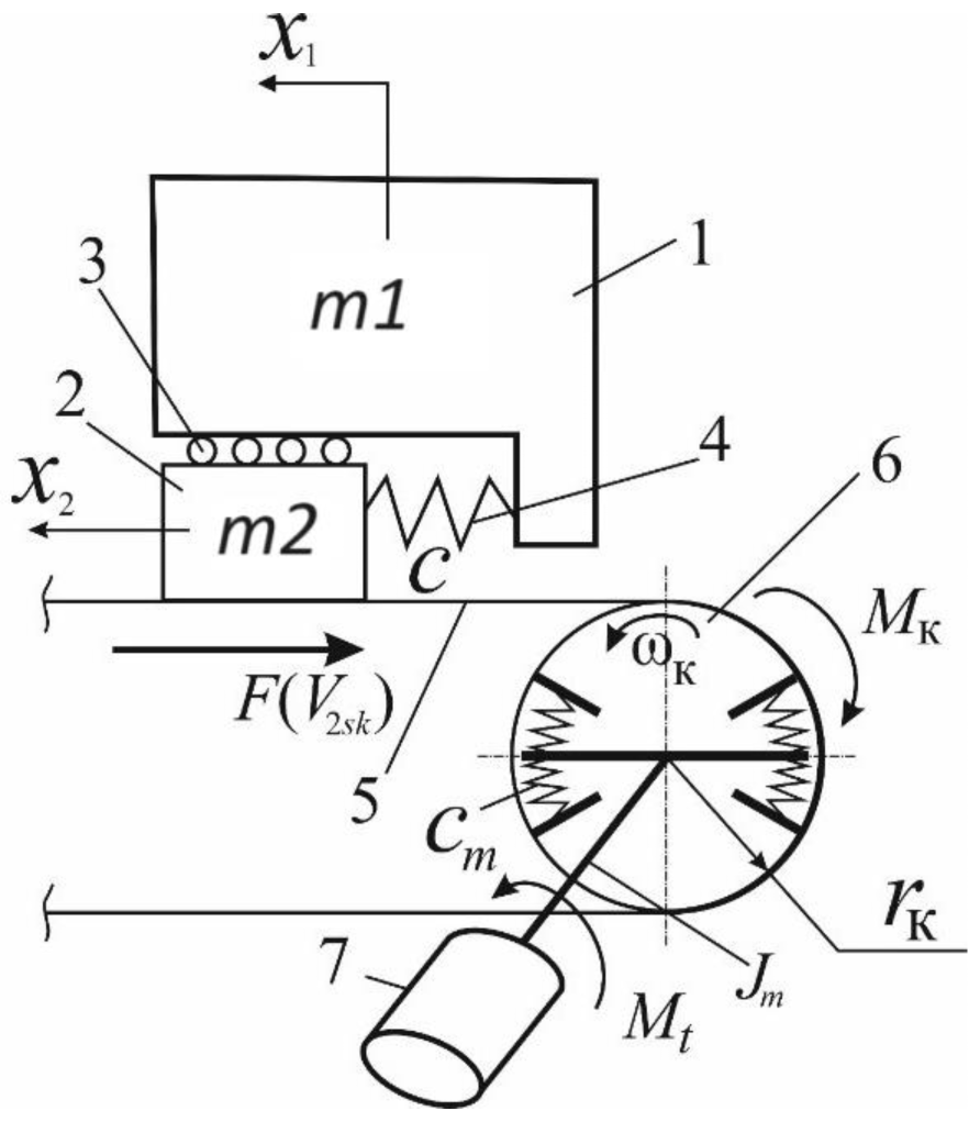
2.2. The Mathematical Model of Frictional Interaction of an Elastic Wheel with a Solid Support Base

The theory of nonlinear differential equations is used to study the dynamics of friction systems. Hence, the study of frictional oscillations in complex systems, especially those with several degrees of freedom, is a complex and often unsolvable problem if the analytical methods are used. Thus, it is reasonable to start the study of frictional oscillations in systems with three degrees of freedom.
Figure 1 presents the calculation scheme of an elastic wheel interaction with a solid support base.
Let us consider two bodies, one of which 1 has mass M and represents the mass of the sprung parts of the car, attributable to the wheel. The second body 2 of mass m plays the role of a sliding wheel. Bodies 1 and 2 are connected with an elastic element 4 having the stiffness c, which characterizes the pliability of the tire in the longitudinal direction. The wheel 2 slips relative to the support base 5, whereby the friction force F V 2 s k   depending on the velocity V 2 s k of the wheel sliding relative to the support base acts on it. The body 1 can slip by means of rollers 3 relative to the body 2 without friction within the action of the elastic force developed by a spring of stiffness c. The support base 5 is represented as a non-stretchable and weightless belt. Impacted by the traction motor 7 the rotation of the wheel 6 with angular velocity ω к causes the movement of the support base 5 with linear velocity ω к r к , i.e., the interaction of the wheel 6 and the tape of the support base 5 occurs without relative sliding. Then, the velocity V 2 s k = V 2 ω к r к , where V 2 is the linear velocity of body 2 in the stationary coordinate system.
In Figure 1  x 1 ,   x 2 —longitudinal displacements of masses 1 and 2, respectively;   F V 2 s k —friction force depending on the velocity V 2 s k of the wheel sliding relative to the support base; ω к —angular speed of wheel rotation; r к —distance from the wheel center to the support base; M t —torque or braking moment developed by traction electric motor; c m —angular “electromagnetic stiffness” of traction synchronous electric motor with permanent magnets, as c m   is the reduced stiffness of all elements from the rotor shaft to the wheel. As will be determined during the control process, M k is the torque on the wheel. J m —moment of inertia of rotating parts of electric motor, reduced to the rotor.
The motion of bodies 1 and 2 is translational in character. Let us introduce the coordinates for the displacement of the bodies. Consider that x 1 —displacement of body 1 in the stationary coordinate system, and x 2 —displacement of body 2 in the stationary coordinate system. We will assume that at x 1 = x 2 = 0 , the spring is undeformed and there is no slippage of mass 2 relative to the supporting base 5, thus F V 2 s k = 0 .
The developed calculation scheme of an elastic wheel interaction with a solid support base allows studying the processes occurring in the interaction zone in different wheel rolling modes, i.e., in the traction, driven, and braking modes.

2.3. The Mathematical Model of Elastic Wheel Friction against a Solid Support Base

The Coulomb dry friction model is the most common. It features the rest friction force that exceeds the sliding friction force (Figure 2a). Such friction models have no derivatives at zero sliding velocity, which causes the appearance of stagnation zones, and the loss of unique solutions due to the variable structure of the right parts of the differential equations. A model of interaction between tires and the supporting base, called the “magic formula” of Pacejka [15] is often used to describe the wheeled machine dynamics—Figure 2b. From a mathematical point of view, the use of such friction laws increases analytical study complexity. Consequently, numerical methods are used to study the dynamics of the systems with nonlinear friction [14].
Two different friction models are used in this problem: one for the case of partial sliding in the interaction zone and another one for the case of complete sliding in the interaction zone.
In the case of partial sliding, we will use a model similar to Pacejka’s “magic formula”, but in a form that is more convenient for analytical study [16]. The friction force F in the interaction zone is defined by the formula:
F V 2 s k = μ s F z
where   μ —coefficient of adhesion; s—slip; F z —vertical reaction in the interaction zone.
The slip s is calculated:
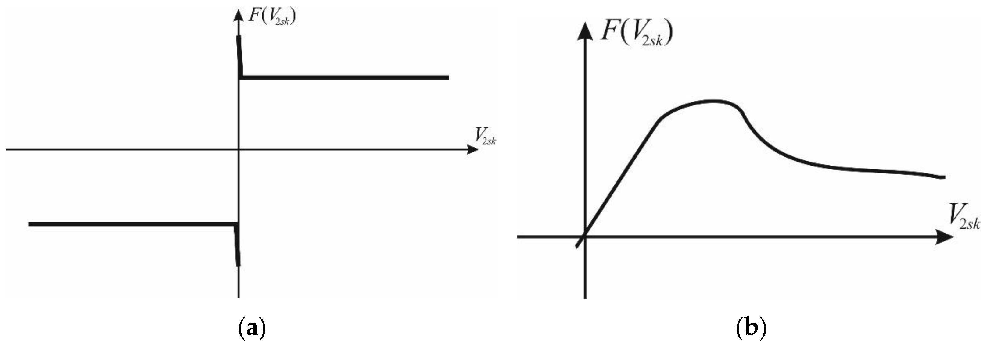
  • − for the wheel rolling braking mode:
s = V 2 ω к r к V 2
  • − for the wheel rolling traction and driven modes:
s = V 2 ω к r к ω к r к
The adhesion coefficient will be determined as follows [16]:
μ s = 2 μ p s p s s p 2 + s 2
where μ p ,   s p are some positive constants. The numerical value of μ p ,   s p is not so important. As will be shown later when analyzing the system of differential equations, the sign of the resulting expression is important.
For the case of complete sliding, we will use the Coulomb friction model (Figure 3), which depends on the relative velocity V 2 s k as a polynomial of degree five [1], which, taking into account the principle of Stribeck, has 3 friction zones: a zone of dry friction, a zone of boundary friction V 21 < V < V 22 and a zone of viscous friction V 22 < V .
F V 2 s k = k V 2 s k 1 g 1 V 2 s k 2 + g 2 V 2 s k 4
where k ,   g 1 ,   g 2 are some constant positive coefficients.
Let us assume the following condition:
g 1 = V 21 2 + V 22 2 V 21 2 V 22 2 .   g 2 = 1 5 V 21 2 V 22 2 ,   V 22 > V 21 > 0
Then, the function F V 2 s k in the region of positive values of the argument has a local maximum at point V 21 and a local minimum at point V 22 and is decreasing on the interval ( V 21 ,   V 22 ) . Suppose that F V 2 s k > 0   when   V 2 s k > 0 . This condition will be satisfied if its local minimum at point V 22   exceeds zero, which will be true if the inequality condition is fulfilled:
15 V 21 2 V 22 2 5 V 21 2 + V 22 2 V 22 2 + 3 V 22 4 > 0 5 V 21 2 > V 22 2   o r   g 1 2 4 g 2 < 0
In the following, we will assume that the function F V 2 s k meets the conditions (9) and (10).
This friction model is used because it is the simplest approximation of the Coulomb friction model when the rest friction force exceeds the sliding friction force. The use of this friction model, as will be shown in the following, will allow an analytical study of occurrence of auto-oscillation.
We shall investigate the peculiarities of the flow modes and conditions for the origin of oscillation processes in an individual traction electric drive based on a synchronous motor with permanent magnet by analyzing the nonlinear oscillations in the zone where an elastic tire interacts with the solid support base irregularities, suggested in [17].

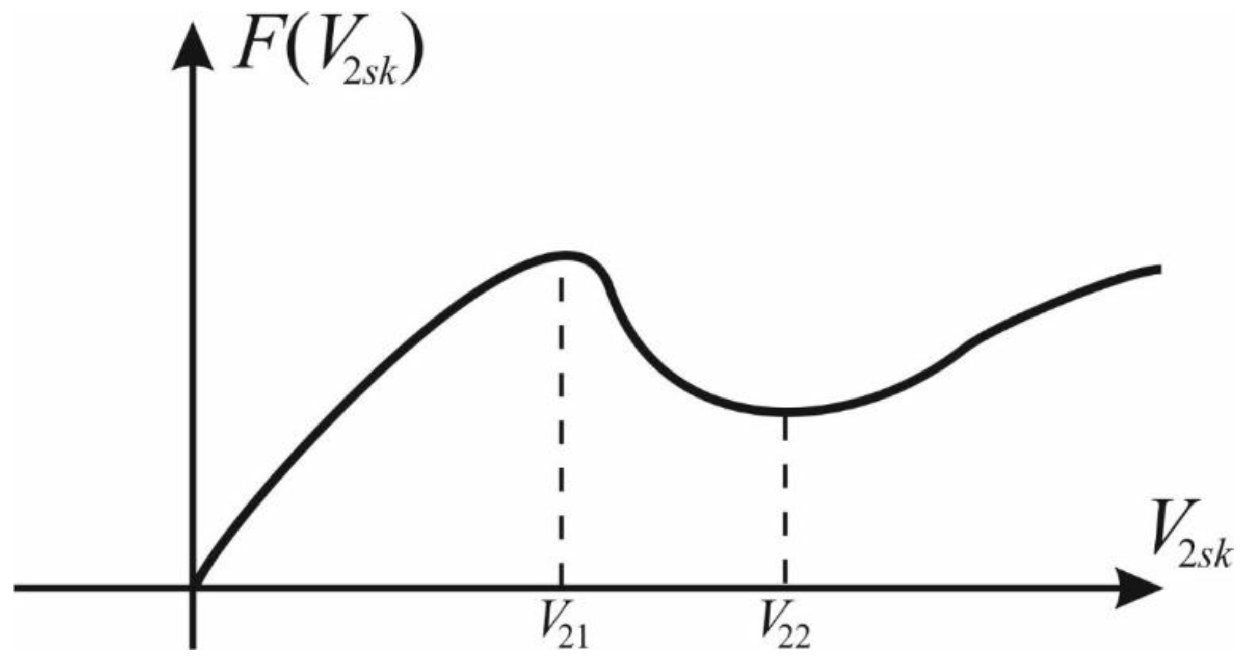
2.4. Analysis of the Occurrence of the Auto-Oscillation Mode for the Traction and Slave Modes of Wheel Rolling on a Solid Support Base

For the calculation scheme shown in Figure 1, let us consider the traction and driven wheel rolling modes.
At partial sliding of the wheel in the driving and driven modes, on the basis of the theorems on conservation of the motion quantity and the motion quantity momentum, let us write down the following differential equations (maintaining the generality, for simplification of further analysis, we assume that the gear ratio of the wheel reducer is equal to one):
x ˙ 1 = V 1 V ˙ 1 = c M x 1 x 2 x ˙ 2 = V 2 V ˙ 2 = 1 m F c x 1 + c x 2 φ ˙ к = ω к ω ˙ к = 1 J к c m φ m φ к F r к φ ˙ m = ω m ω ˙ m = 1 J m c m φ m φ к + M t
where J к ,   J m —the moments of inertia of the wheel and the moment of inertia of the wheel motor-reducer reduced to the rotor of the traction motor, respectively, relative to the axis of their rotation, φ m —traction motor rotor shaft rotation angle, and φ к —wheel angle.
Friction force F is determined by Formula (4), the coefficient of adhesion μ s —by Formula (7), slip s is calculated by Formula (6).
Let us consider the possibility of the occurrence of auto-oscillation in the considered wheel rolling mode with the help of Bendixson’s criterion. For the translational displacement of body 1 (Figure 1):
Q = f 1 x 1 + f 2 V 1 0
Identical equality to zero of the function Q means the possibility of the occurrence of auto-oscillation of the body 1 translational displacement. The same conclusion can be made regarding the rotation of the rotor of the traction synchronous electric motor with permanent magnets.
We obtain Q > 0 as for the translational motion of body 2, and for the rotational motion of the wheel, i.e., the function is sign-constant and in zero identically does not turn. Consequently, we can conclude that in the traction and driven wheel rolling modes at its partial sliding in the interaction zone, the autopoietic processes cannot arise.
At full sliding of the wheel in the driving and driven modes for the system of Equation (11), the friction force F will be determined by Formulas (8)–(10). Then, for the translational displacement of body 1 (Figure 1), we again obtain the expression (12) for the function Q, which also means the possibility of the occurrence of body 1 translational displacement auto-oscillation. Again, this conclusion can be extended to cover the traction motor rotor rotation.
For the translational displacement of body 2 (Figure 1):
f 1 x 2 = 0 ; f 2 V 2 = k m 1 3 g 1 V 2 s k 2 + 5 g 2 V 2 s k 4
In order to decide if the Q function is variable, let us examine the roots of the equation.
5 g 2 V 2 s k 4 3 g 1 V 2 s k 2 + 1 = 0
Let us introduce the substitution of variables z = V 2 s k 2 . Then, Equation (14) will take the form:
5 g 2 z 2 3 g 1 z + 1 = 0
Let us find the discriminant D of Equation (15).
D = 9 g 1 2 20 g 2
If D > 0, then Equation (15) will have two real roots and the function Q will be sign-variable. If D = 0, then Equation (15) will have one real root, and the function Q will be sign-variable. If D < 0, then Equation (15) will have no real roots, and the function Q will be sign-constant.
Based on the expression (16), taking into account (9) and (10), one can conclude that:
D = V 21 V 22 2 > 0
Consequently, the function Q is a sign-variable, which indicates the occurrence of auto-oscillations for translational movement of the wheel center in the traction and driven wheel rolling modes at its full sliding.
Let us investigate the occurrence of the auto-oscillation mode according to criterion (3) for the translational displacement of the wheel center L < 0.
Thus, in the traction and driven modes, we have the occurrence of a “soft” mode of auto-oscillation for the translational wheel center movement. In this case, the conditions for the occurrence of the “soft” excitation of auto-oscillations arise in the vehicle motion, when the sliding speed of the wheels falls into the region characterized by an increasing friction force with a decreasing sliding speed, i.e., when V 21 < V 2 < V 22 (Figure 3). Thereafter, when the sliding velocity decreases, the auto-oscillations disappear.
For the rotational motion of the wheel:
f 1 φ к = 0 ;
f 2 ω к = k r к 2 J к 1 3 g 1 V 2 s k 2 + 5 g 2 V 2 s k 4
Further calculations (14)–(17), and the conclusion about the occurrence of oscillations for the rotational motion of the wheel in the traction and driven full-sliding wheel rolling modes, fully correspond to the previous case.
Let us investigate the occurrence of the auto-oscillation mode according to criterion (3) for the rotational motion of the wheel L < 0, which indicates the occurrence of a “soft” mode of auto-oscillation.

2.5. Analysis of the Occurrence of Auto-Oscillation for the Braking Mode of the Wheel Rolling on a Solid Support Base

For the calculation scheme shown in Figure 1, let us consider the braking mode of the wheel rolling under the regenerative braking for partial sliding wheel case (no blocking).
Based on the motion and momentum conservation theorems, let us write down the following differential equations:
x ˙ 1 = V 1 V ˙ 1 = c M x 1 + x 2 x ˙ 2 = V 2 V ˙ 2 = 1 m F + c x 1 c x 2 φ ˙ к = ω к ω ˙ к = 1 J к c m φ m φ к + F r к M к φ ˙ m = ω m ω ˙ m = 1 J m c m φ m φ к M t
where M к —is the braking torque developed by the wheel brake mechanism.
For wheel braking mechanisms using the analogy with the friction model (8)–(10) for the tire, let us write down an approximation of the dependence of the braking torque M к , developed by the wheel braking mechanism, on the angular velocity ω к of the wheel rotation:
M к ω к = k ω к 1 g 3 ω к 2 + g 4 ω к 4
where k ,   g 3 ,   g 4 are some constant positive coefficients.
Friction force F is determined by Formula (4), the coefficient of adhesion μ s —by Formula (7), the slip s is calculated by Formula (6). At regenerative braking the braking torque M к = 0 .
Let us again consider the possibility of the occurrence of auto-oscillation in the considered wheel rolling mode with the help of Bendixson’s criterion.
For the translational displacement of body 1 (Figure 1), we obtain the expression (12) for the function Q, which also stands for the possibility of the occurrence of body 1 translational displacement auto-oscillation. The same conclusion can be extended to the rotation of the traction motor rotor.
For the translational displacement of the body 2 (Figure 1):
f 1 x 2 = 0 ;   f 2 V 2 > 0
For the rotational motion of the wheel:
f 1 φ к = 0 ;   f 2 ω к = < 0
In the last two cases, the function Q is sign-constant and does not convert to zero identically. Consequently, we can conclude that in the braking wheel rolling mode at the partial sliding in the interaction zone, oscillation processes cannot occur.
For the complex braking mode (with the help of mechanical braking mechanisms plus regenerative braking at the expense of traction electric motor), let us consider the case of rolling when both regenerative M t and braking M к moments are applied to the wheel. Let us consider the rotational motion of the wheel.
f 1 φ к = 0
f 2 ω к = 2 J к r к 2 V 1 F z s p μ p 1 s p 2 1 V 1 ω к 2 + V 1 2 ω к 3 k + 3 k g 3 ω к 2 5 k g 4 ω к 4
In this case, the function Q = f 1 φ к + f 2 ω к is a sign-variable, which indicates the possibility of the occurrence of auto-oscillation L < 0 .
We have a “soft” mode of auto-oscillation excitation. This mode of transmission loading is dangerous, because intensive braking causes a sharp increase in the auto-oscillation amplitudes [18,19,20,21,22,23,24,25], which can lead to the car “jerking” longitudinally, and transmission unit teeth, cardan shaft, joint and semi-axle breakdown. Therefore, to avoid breakdowns during the intensive braking at high initial speeds, it is necessary to reduce the total braking torque, for example, by reducing the regenerative torque of the traction motor.
At full sliding of the wheel, in case of its blocking, on the basis of the theorems on conservation of the quantity of motion and momentum, we write down the following differential equations:
x ˙ 1 = V 1 V ˙ 1 = c M x 1 + x 2 x ˙ 2 = V 2 V ˙ 2 = 1 m F + c x 1 c x 2
For the system of Equation (11), the friction force F will be determined by Formulas (8)–(10). Then, again we come to system (13) with the conclusion that the function Q is a sign-variable, which indicates the occurrence of auto-oscillations for the translational displacement of the body 2 (Figure 1) in the zone of interaction of the elastic wheel with a solid support base in the braking mode of rolling of the wheel at its blocking.
Let us investigate the occurrence of the auto-oscillation mode according to criterion (3) for translational displacement of body 2 L > 0 .
Thus, in the braking mode, we have the occurrence of the “rigid” auto-oscillation mode in the interaction zone. In this case, the conditions for the occurrence of “rigid” auto-oscillation excitation arise during the car braking, when the sliding speed of the locked wheels falls into the region characterized by a decrease in the friction force when the sliding speed decreases, i.e., when 0 < V 2 < V 21 (Figure 3).

3. Results

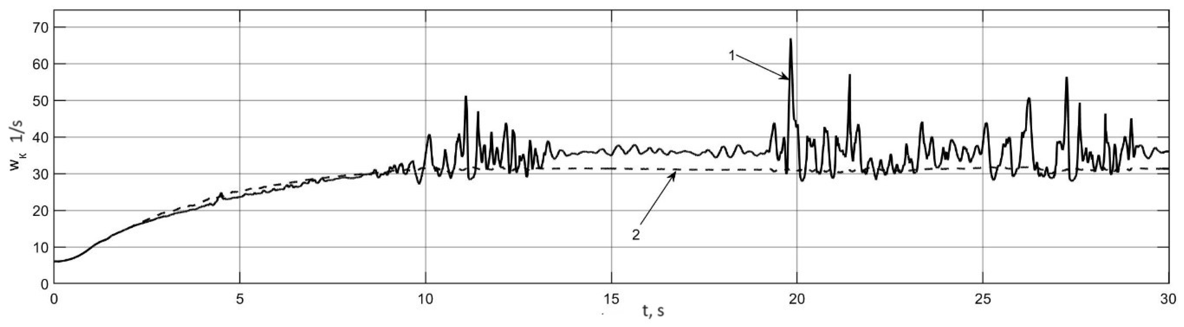
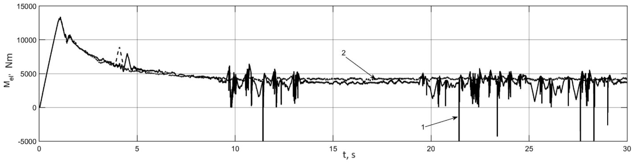
3.1. Research of the Occurrence of the Auto-Oscillation Mode in Individual Traction Electric Drive by Simulation Mathematical Modeling

Auto-oscillation onset and development in the interaction zone were researched by the theoretical studies into the motion of an electric bus with a total mass of 18,000 kg conducted with the help of Matlab Simulink simulation mathematical modeling. The features of the motion mathematical model are outlined in [26,27,28,29,30,31,32]. The term “support base” means only a hard-uneven non-deformable support surface, which can be characterized as an “asphalt–concrete highway”. The parameters of the traffic modes modeled are shown in Table 1.
Figure 4 and Figure 5 illustrate the mode of motion in simulation mathematical modeling. Figure 4 shows the trajectory of the vehicle in a turn on dry asphalt. Figure 5 shows the process of movement speed change in time, and Figure 6 presents the angular velocities of the driving wheels rolling in the driving mode. Figure 7 shows the process of time variation in the torques on the drive wheels.
The analysis of Figure 6 and Figure 7 shows that in the process of acceleration in a turn on dry asphalt, oscillation processes occur synchronously both on torques and angular velocity oscillograms. This occurs at the inner leading wheel as related to the rotation direction (left when turning to the left), which is unloaded vertically due to the impact of centrifugal forces during rotation. The leading wheel of the opposite side, which, on the contrary, is additionally vertically loaded, which increases the grip with the supporting base, has no auto-oscillations. It should also be noted that the intensity and frequency of angular velocity oscillations are different, which is related to the previously mentioned character (soft or hard) of their excitation. The intensity of auto-oscillations of torques brought to the wheel is quite high and can reach the 500 Nm lever (with peak values up to −5000 Nm), which can cause wheel reducer teeth and traction motor bearing breakdown.
Figure 8 shows the trajectory of the vehicle in a turn on snowy ice. Figure 9 shows the movement speed change over time, Figure 10 shows the angular velocities of the driving wheels rolling in the driving mode, and Figure 11 shows the process of time variation in torques on the driving wheels.
The analysis of Figure 8, Figure 9, Figure 10 and Figure 11 shows that during the acceleration in a turn on ice, there was a skidding of the rear axle and there were intensive auto-oscillations of both angular velocity and torque of both the driving wheels. In this case, the amplitudes of torques can reach 6000 Nm per wheel, which can lead to the destruction of wheel gear teeth and traction motor bearings.
Figure 12 shows the trajectory of the electric bus when braking in a turn on snowy ice, Figure 13 shows the speed of movement, Figure 14 shows the angular velocities of the driving wheels, and Figure 15 shows the regenerative moments transmitted to the driving wheels.
The analysis of graphs in Figure 13, Figure 14 and Figure 15 shows that when an electric bus was breaking in a turn on snowy ice, the skidding of the rear axle occurred and the inner (as related to the rotation direction) leading wheel was blocked earlier than that of the outer one. No auto-oscillation of the angular velocities of the wheels during braking was observed, and the oscillograms of regenerative torques on the driving wheels clearly showed the areas where the auto-oscillations occurred.

3.2. Determination of the Auto-Oscillation Frequency in a Traction Electric Drive

As shown in [33], depending on the sliding velocity V 2 s k , the period of auto-oscillations in the nonlinear system, the calculation scheme of which is shown in Figure 1, will vary depending on the period T c T = 2 π c m J m of the natural stationary oscillations of the conservative system up to the value τ = π c m J m + 2 R 1 R 2 c m ω к at nonstationary oscillations (here R 1 ,   R 2 —rest friction force and motion friction force, respectively). Thus, it can be concluded that when autocolevations occur in an individual traction electric drive, their frequency will vary depending on the amount of the wheel sliding relative to the supporting base.
However, in the considered case, as it was shown earlier, the oscillations in the system are excited by the forces of interaction between the elastic tire and the supporting base. The oscillation of the process of the traction motor rotor rotation is additionally imparted to the vertical oscillations of the wheel due to the elastic nature of its interaction with the uneven road. These oscillations, in turn, lead to the oscillatory character of the vertical reaction in the interaction zone and, as a consequence, to the longitudinal reaction.
To investigate the synchronism in the frequency of traction motor torque oscillations, the angular rotation velocity of the driving wheel and the radial tire deformation, we simulate the straight—on acceleration of an electric bus on dry asphalt. Figure 16 shows fragments of the traction motor torque, the driving wheel rotation angular velocity and the radial tire deformation, where the auto-oscillations were observed. Figure 17 shows the spectral energy densities of the same processes.
As Figure 17 shows, the natural oscillation frequencies of all three processes coincide. This allows for the conclusion that the frequencies of the autocolevation processes of the traction motor torque and the angular velocity of the driving wheel rotation were caused by the vertical oscillations frequency of the elastic wheel when moving over the unevenness of the supporting base.

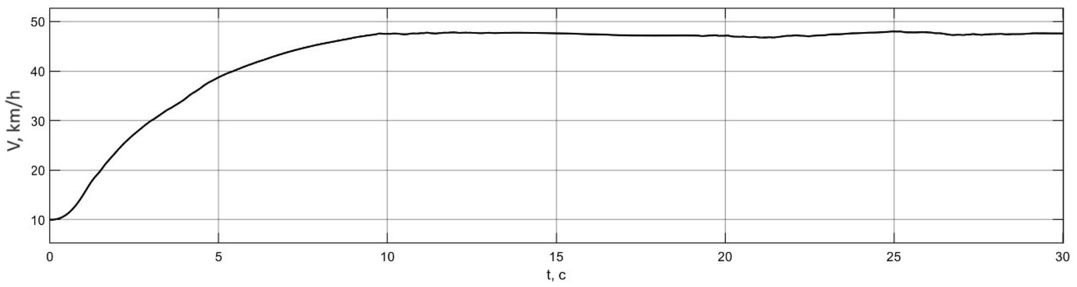
3.3. Experimental Investigation of the Occurrence of the Auto-Oscillation Modes in an Individual Traction Electric Drive

The conclusions regarding the flow modes and the conditions for the auto-vibration processes origin in an individual traction electric drive were verified using the tests on the electric bus. Table 2 presents its characteristics, while Figure 18 shows the general view and scheme of the individual electric drive.
The tests featured the electric bus moving along a straight road section with variable speed. The following values were recorded: the electric torque of the rear left driving wheel, reduced to the wheel, Nm; the angular velocity of rotation of the rear left driving wheel, 1/s.
Figure 19 shows a characteristic fragment of the traction electric torque realization obtained during the tests. Figure 20 shows the same obtained as a result of simulation of the electric bus motion under the same conditions. Figure 21 shows the spectral energy density of the traction motor torque energy for the realization obtained experimentally (Figure 19).
The analysis of Figure 19 and Figure 20 shows that the character of the torque realizations obtained experimentally and with a simulation are identical, both realizations show auto-oscillatory processes due to the wheels vertical oscillations. The energy spectral density of the experimentally obtained torque variation process (Figure 21) is completely identical to the same characteristic (Figure 17a) for the process obtained by simulation. The auto-oscillation frequency for the theoretical and experimental processes is 6–7 Hz, which indicates the high reliability of the electric bus mathematical model.
Figure 22, Figure 23 and Figure 24 show similar plots for the angular velocity of the wheel.
The analysis of Figure 22 and Figure 23 shows that the character of the wheel angular velocity realizations obtained experimentally and by simulation are identical. Both realizations show auto-oscillatory processes due to vertical wheel oscillations. The energy spectral density of the experimentally obtained wheel angular velocity variation process (Figure 24) is completely identical to that (Figure 17b) of the simulated process. The auto-oscillation frequency for the theoretical and the experimental processes is 6–7 Hz, which indicates the high reliability of the electric bus mathematical model.
For the increased reliability of conclusions regarding the modes of flow and conditions for the origin of autocoletive processes in the individual traction electric drive, additional running tests of the electric bus (Figure 18a) were conducted on a straight section of an asphalt highway with constant pressure on the accelerator pedal. At that, the following values were recorded (Figure 25): accelerator pedal position, %; electric torque of the rear left driving wheel reduced to the wheel, Nm; angular velocity of rotation of the rotor of the rear left electric motor, rpm.
Figure 25 shows that even at a strictly constant accelerator pedal pressure, the realizations of torque and rotor angular velocity clearly show auto-oscillations due to radial deformation of the elastic tire. Figure 26 and Figure 27 show the spectral energy densities for torque and rotor angular velocity.
As in the previous case, the experimental spectral densities (Figure 27 and Figure 28) are completely identical to the theoretical ones. The frequency of auto-oscillation for the theoretical and experimental processes is 6–7 Hz, which indicates the high reliability of the mathematical model of the electric bus.

3.4. Investigation of Auto-Oscillation Modes in the Actual Traction Electric Drive of an Electric Bus

The occurrence of the auto-oscillation modes in the traction electric drive of an electric bus were studied under various real operational conditions. Figure 28 shows the results of the electric bus acceleration up to 20 km/h with subsequent complex (regenerative and mechanical brakes) braking. Figure 28 clearly illustrates that as soon as the regenerative torque (negative current) appeared on the traction motors, the graphs of change in the motor torque and angular velocities of the wheels and rotors clearly show the beginning of auto-oscillations, which fully corresponds to the obtained analytical conclusions for complex braking. Figure 29 shows the results of acceleration of the electric bus with fully depressed accelerator pedal to the maximum speed and with increased wheel slippage.
Figure 29 clearly shows that as the speed of motion increases, there is an increase in the amplitudes of oscillation processes, which is explained by the increase in the slip of the wheels on the support base.
Figure 30 shows the dependences of torques and currents of electric motors on time at driving wheel slippage (the graphs also show that the traction control system is activated). It can be seen that the slippage is accompanied by the auto-oscillations onset.
These graphs (Figure 29 and Figure 30) also confirm the analytical conclusions about the occurrence of auto-oscillation processes in the traction mode when the driving wheels slip.
Figure 31 shows a fragment of torque realization in urban driving. This graph shows that auto-oscillations in traction electric drive with permanent magnet synchronous motors are always present. However, the auto-oscillation amplitude increases significantly with the abrupt torques change, which is always accompanied by the increased slippage of the driving wheels.
The auto-oscillation processes during the sharp change in torques on the driving wheels of an electric bus during acceleration and braking are especially dangerous, as they can cause wheel reducer teeth breakdown.

4. Conclusions

An engineering technique to analyze the conditions for the occurrence of auto-oscillating processes in traction electric drive has been developed. The technique revealed the most dangerous loading of nodes and units of the electric drive of the driving wheels, as well as the setting torque modes at the design stage, and helps to develop recommendations on how to reduce their dynamic loading.
The conditions for the occurrence of oscillation processes in the zone of interaction of an elastic tire with a solid support base in three rolling modes are considered, i.e., traction, driven, and braking. The analytical research established that in the traction, driven and braking wheel rolling modes at partial sliding in the zone of interaction of elastic tires with a solid support base, no oscillation processes of angular velocity arise. In the traction and driven modes, the occurrence of a “soft” mode of the angular wheel rotation velocity auto-oscillations, the wheel sliding velocity is characterized by an increase in the friction force and the sliding velocity decreases. In the complex braking mode (with the help of mechanical braking mechanisms plus regenerative braking with a traction electric motor), there is a “soft” auto-oscillation excitation mode. This mode of transmission loading is dangerous, because the intensive braking features a sharp increase in the amplitudes of auto-oscillations, which can lead to longitudinal “jerking” of the car, transmission unit teeth, cardan shaft, joint, half-axle breakdown, etc. Therefore, intensive braking at high initial speeds requires reducing the total braking torque, for example, by reducing the regenerative torque of the traction motor to prevent any breakdowns. The braking mode features the occurrence of a “rigid” auto-oscillation mode in the translational motion of the wheel center when the sliding velocity of the blocked wheels is characterized by the friction force and the sliding velocity reduction. As auto-oscillations occur in the individual traction electric drive, their frequency will vary depending on the value of the wheel sliding relative to the supporting base.
Simulation modeling of electric bus motion established that in the process of acceleration in a turn on a support base with high adhesion properties, auto-oscillation processes occur synchronously both on torque and angular velocity oscillograms. This occurs in relation to the rotation direction at the inner drive wheel, which is vertically unloaded due to the action of the centrifugal forces during rotation. In the case of the drive wheel of the opposite side, which, on the contrary, is additionally vertically loaded, increasing the grip with the supporting base, no auto-oscillations occur. It should also be noted that the intensity and frequency of angular velocity oscillations are different, which is related to the previously mentioned character (soft or hard) of their excitation. The auto-oscillations of torques reduced to the wheel are quite intense and can reach the level of approximately 500 Nm (with peak values up to −5000 Nm), which can destroy the teeth of the wheel reducer and the bearings of the traction motor.
Simulation modeling of an electric bus motion established that the process of acceleration in a turn on a support base with low adhesion properties is associated with the possible skidding of the rear axle skidding. Thus, there were intensive autocolevations of both angular velocity and torque of the unloaded driving wheel. In this case, the amplitudes of torques can reach 4000 Nm on the wheel, which can destroy the teeth of the wheel gearbox and the bearings of the traction motor.
Simulation modeling established that the braking of an electric bus in a turn on dry asphalt is associated with the earlier blocking of the inner leading wheel compared to the outer one. No auto-oscillation process of the angular velocities of the wheels during braking is observed, and the oscillograms of the regenerative torques on the driving wheels clearly show zones where the auto-oscillations occurred.
The frequencies of auto-oscillation processes of the traction motor torque and angular speed of driving wheel rotation are caused by the frequency of elastic wheel vertical oscillations associated with moving over irregularities of the supporting base.
Thus, the following main results of this study can be emphasized:
  • The developed mathematical model describing the process of auto-oscillations of an electric vehicle of high reliability (confirmed by test results).
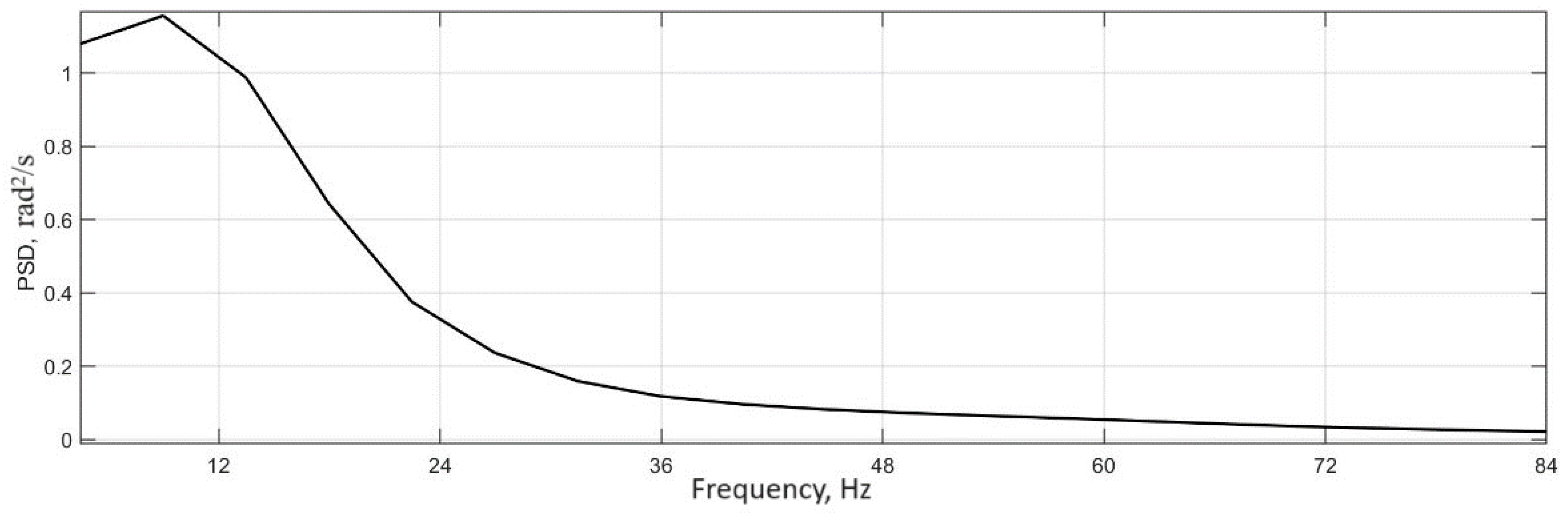
  • Based on the results of simulation modeling, the frequencies of tire oscillations are determined, which are 6–7 Hz and coincide with the frequency of auto-oscillations to realize the frequency of rotation of the electric motor shaft.
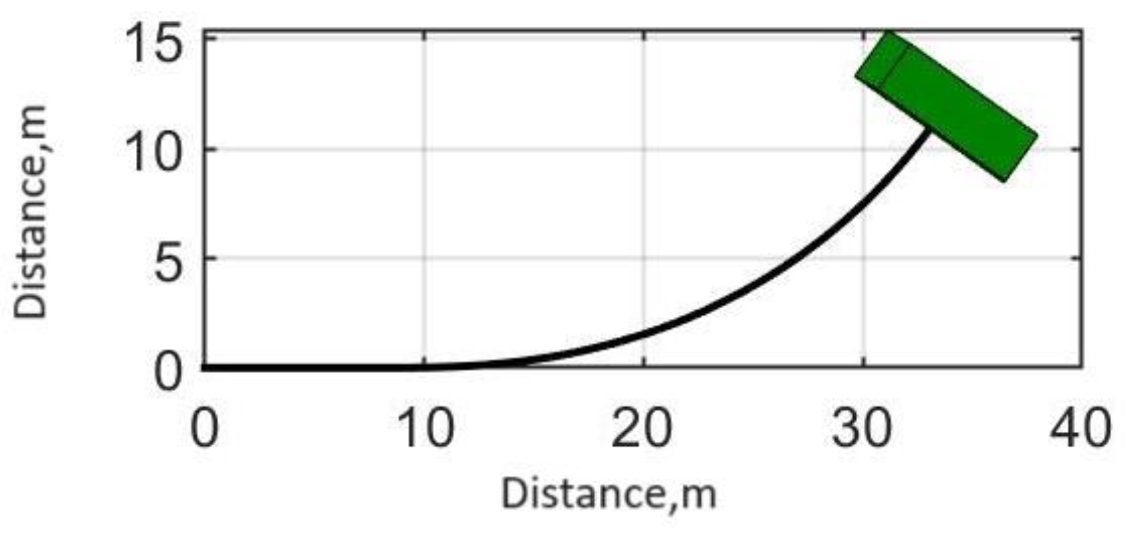
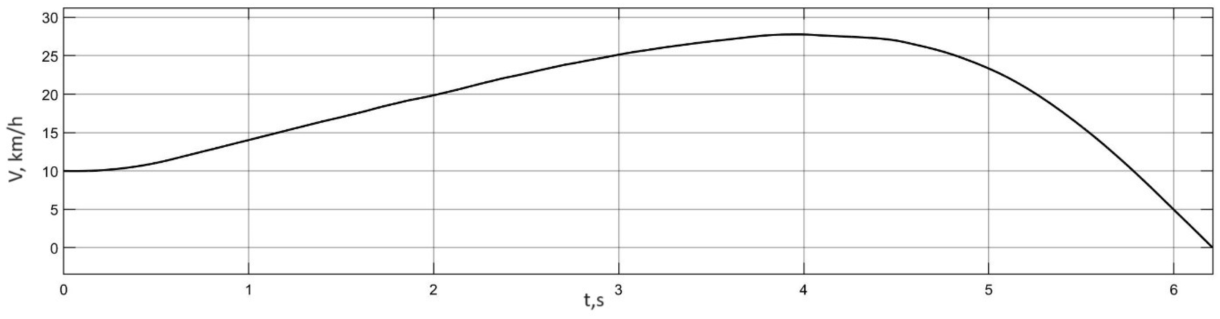
  • Correctness of the results of theoretical research and the results of simulation modeling are confirmed by experimental studies of the process of the occurrence of auto-vibration phenomena in the movement of the vehicle to the support base.
The practical value of this study lies in the possibility of using the results of this study in the development of algorithms for the exclusion of auto-vibration phenomena in the development of vehicle control systems, as well as the application of the method of analyzing the origin and flow of auto-vibration processes in the design of the drive wheels of the vehicle.

Author Contributions

Formal analysis, investigation, and resources, A.V.K. (Alexander V. Klimov), B.K.O. and Y.M.F.; writing—original draft preparation and writing—review and editing, D.A.M.; supervision and project administration, S.S.S.; funding acquisition, A.V.K. (Andrey V. Keller). All authors have read and agreed to the published version of the manuscript.

Funding

The research was carried out with the financial support of the Ministry of Science and Higher Education of the Russian Federation within the framework of the project “Development of a mathematical model of chassis operation (transmission, chassis and control mechanisms) in static and dynamic states and creation of a digital twin of a passenger car platform on its basis” (code: FZRR-2023-0007).

Data Availability Statement

Data are contained within the article.

Conflicts of Interest

Alexander V. Klimov and Baurzhan K. Ospanbekov are employees of LLC KAMAZ Innovation Center. The paper reflects the views of the scientists, and not the company.

References

  1. Vilke, V.G.; Shapovalov, I.L. Auto Oscillations in the Process of Car Braking; Series 1: Mathematics. Mechanics; Bulletin of Moscow University: Moscow, Russia, 2015; pp. 33–39. [Google Scholar]
  2. Svetlitsky, V.A. Random Vibrations of Mechanical Systems; Mashinostroenie: Moscow, Russia, 1976; 216p. [Google Scholar]
  3. Kruchinin, P.A.; Magomedov, M.K.; Novozhilov, I.V. Mathematical Model of an Automobile Wheel on Antiblock Motion Modes; MTT Series; Izvestiya RAN: Moscow, Russia, 2001; pp. 63–69. [Google Scholar]
  4. Awrejcewicz, J.; Dzyubak, L.; Grebogi, C. Estimation of Chaotic and Regular (Stick–Slip and Slip–Slip) Oscillations Exhibited by Coupled Oscillators with Dry Friction. Nonlinear Dyn. 2015, 42, 383–394. [Google Scholar] [CrossRef]
  5. Pascal, M. Dynamics and Stability of a Two Degree of Freedom Oscillator with an Elastic Stop. J. Comput. Nonlinear Dyn. 2006, 1, 94–102. [Google Scholar] [CrossRef]
  6. Shin, K.; Brennan, M.J.; Oh, J.E.; Harris, C.J. Analysis of disc brake noise using a two-degree-of-freedom model. J. Sound Vib. 2002, 254, 837–848. [Google Scholar] [CrossRef]
  7. Kotiev, G.O.; Padalkin, B.V.; Kartashov, A.B.; Dyakov, A.S. Designs and development of Russian scientific schools in the field of cross-country ground vehicles building. ARPN J. Eng. Appl. Sci. 2017, 12, 1064–1071. [Google Scholar]
  8. Ergin, A.A.; Kolomejtseva, M.B.; Kotiev, G.O. Antiblocking control system of the brake drive of automobile wheel. Prib. Sist. Upr. 2004, 9, 11–13. [Google Scholar]
  9. Moaaz, A.O.; Ali, A.S.; Ghazaly, N.M. Investigation of Anti-Lock Braking System Performance Using Different Control Systems. Int. J. Control Autom. 2020, 13, 137–153. [Google Scholar]
  10. Sun, C.; Pei, X. Development of ABS ECU with Hardware-in-the-Loop Simulation Based on Labcar System. SAE Int. J. Passeng. Cars-Electron. Electr. Syst. 2014, 8, 14–21. [Google Scholar] [CrossRef]
  11. Sabbioni, E.; Cheli, F.; D’alessandro, V. Analysis of ABS/ESP Control Logics Using a HIL Test Bench; SAE International: Warrendale, PA, USA, 2011. [Google Scholar] [CrossRef]
  12. Hart, P.M. Review of Heavy Vehicle Braking Systems Requirements (PBS Requirements); Draft Report. Available online: https://trid.trb.org/View/1407753 (accessed on 24 April 2003).
  13. Marshek, K.M.; Cuderman, J.F.; Johnson, M.J. Performance of Anti-Lock Braking System Equipped Passenger Vehicles Part I: Braking as a Function of Brake Pedal Application Force. In Proceedings of the SAE 2002 World Congress, Detroit, MI, USA, 4–7 March 2002. [Google Scholar]
  14. Kuznetsov, A.P.; Kuznetsov, S.P.; Ryskin, N.M. Nonlinear Oscillations; Fizmatlit: Moscow, Russia, 2002; 292p. [Google Scholar]
  15. Pacejka, H.B. Tyre and Vehicle Dynamics, 2nd ed.; Butterworth Heinemann: Oxford, UK, 2006; 672p. [Google Scholar]
  16. Wellstead, P.E.; Pettit, N.B. Analysis and Redesign of an Antilock Brake System Controller. IEE Proc. Control Theory Appl. 1997, 144, 413–426. [Google Scholar] [CrossRef]
  17. Zhileikin, M.M. Investigation of Autocoletive Processes in the Zone of Interaction of an Elastic Tire with a Solid Support Base. Izvestiya vysshee obrazovaniya vysshee obrazovaniya. Mashinostroenie 2021, 10, 3–15. [Google Scholar] [CrossRef]
  18. Chelomey, V.N. Vibrations in Engineering; Volume 2: Fluctuations of Nonlinear Mechanical Systems; Blekhman, I.I., Ed.; Mashinostroenie: Moscow, Russia, 1979; 351p. [Google Scholar]
  19. Kryukov, B.I. Forced Vibrations of Essentially Nonlinear Systems; Mashinostroenie: Moscow, Russia, 1984; 216p. [Google Scholar]
  20. Nekorkin, V.I. Lectures on the Fundamentals of Vibration Theory: Textbook; Nizhny Novgorod University: Nizhny Novgorod, Russia, 2011; 233p. [Google Scholar]
  21. Babakov, I.M. Theory of Vibrations, 4th ed.; Drofa: Moscow, Russia, 2004; 591p. [Google Scholar]
  22. Strelkov, S.P. Introduction to the Theory of Vibrations; Nauka: Moscow, Russia, 1964; 438p. [Google Scholar]
  23. Yablonsky, A.A.; Noreiko, S.S. Course of the Theory of Vibrations; Lan: Moscow, Russia, 2003; 256p. [Google Scholar]
  24. Moiseev, N.N. Asymptotic Methods of Nonlinear Mechanics; Izd. “Nauka”, Main Editorial Office of Physical and Mathematical Literature: Moscow, Russia, 1969; 380p. [Google Scholar]
  25. Bogolyubov, N.N.; Mitropolsky, Y.A. Asymptotic Methods in the Theory of Nonlinear Oscillations; Nauka: Moscow, Russia, 2005; Volume 3, 605p. [Google Scholar]
  26. Gorelov, V.A.; Komissarov, A.I.; Miroshnichenko, A.V. 8 × 8 wheeled vehicle modeling in a multibody dynamics simulation software. Procedia Eng. 2015, 129, 300–307. [Google Scholar] [CrossRef]
  27. Keller, A.V.; Gorelov, V.A.; Anchukov, V.V. Modeling truck driveline dynamic loads at differential locking unit engagement. Procedia Eng. 2015, 129, 280–287. [Google Scholar] [CrossRef]
  28. Volskaya, V.N.; Zhileykin, M.M.; Zakharov, A.Y. Mathematical model of rolling an elastic wheel over deformable support base. IOP Conf. Ser. Mater. Sci. Eng. 2018, 315, 012028. [Google Scholar] [CrossRef]
  29. Belousov, B.; Ksenevich, T.; Vantsevich, V.; Komissarov, D. 8 × 8 Platform for Studing Terrain Mobility and Traction Performance of Unmanned Articulated Ground Vehicles with Steered Wheels. SAE Tech. Pap. 2013, 9. [Google Scholar] [CrossRef]
  30. Belousov, B.; Shelomkov, S.; Ksenevich, T.; Kupreyanov, A. Experimental verification of a mathematical model of the wheel-supporting surface interaction during nonstationary rolling motion. J. Mach. Manuf. Reliab. 2009, 38, 501–505. [Google Scholar]
  31. Wong, J.Y. Theory of Ground Vehicles; Wiley: New York, NY, USA, 2001; 560p. [Google Scholar]
  32. Antonyan, A.; Zhileykin, M.; Eranosyan, A. The algorithm of diagnosing the development of a skid when driving a two-axle vehicle. In Proceedings of the Design Technologies for Wheeled and Tracked Vehicles (MMBC) 2019, Moscow, Russia, 1–2 October 2019; Volume 820. [Google Scholar] [CrossRef]
  33. Polungyan, A.A.; Fominykh, A.B.; Staroverov, N.N. Dynamics of Wheeled Machines; Polungyan, A.A.A., Ed.; Bauman Moscow State Technical University Publishing House: Moscow, Russia, 2013; 118p, ISBN 978-5-7038-3706-1. [Google Scholar]
Figure 1. Calculation scheme of interaction of an elastic wheel with a solid support base: 1—mass m1 of sprung parts of the car falling on the wheel; 2—mass m2 of the wheel; 3—rollers; 4—elastic element characterizing the pliability of the tire in the longitudinal direction; 5—support base; 6—rotating wheel; 7—traction motor; c—spring stiffness.
Wevj 14 00316 g001
Figure 2. Dependence of friction force F on relative sliding velocity V 2 s k for the Coulomb dry friction model (a) and for Paseika’s “magic formula” (b).
Wevj 14 00316 g002
Figure 3. Dependence of friction force F on relative sliding velocity V2sk for model (8).
Wevj 14 00316 g003
Figure 4. Trajectory in a corner on dry asphalt.
Wevj 14 00316 g004
Figure 5. Process of time variation in speed in a turn on dry asphalt.
Wevj 14 00316 g005
Figure 6. Angular velocities of the driving wheels in a turn on dry asphalt: 1—left rear wheel; 2—right rear wheel.
Wevj 14 00316 g006
Figure 7. Process of time variation in torques on the driving wheels in a turn on dry asphalt: 1—left rear wheel; 2—right rear wheel.
Wevj 14 00316 g007
Figure 8. Trajectory of movement in a turn on ice with snow.
Wevj 14 00316 g008
Figure 9. Process of time variation in speed in a turn on snow-covered ice.
Wevj 14 00316 g009
Figure 10. Angular velocities of the driving wheels in a turn on ice with snow: 1—left rear wheel; 2—right rear wheel.
Wevj 14 00316 g010
Figure 11. Process of change in time of torques on the driving wheels in a turn on ice with snow: 1—left rear wheel; 2—right rear wheel.
Wevj 14 00316 g011
Figure 12. Trajectory of motion during braking in a turn on ice with snow.
Wevj 14 00316 g012
Figure 13. Process of change in time of movement speed during braking in a turn on ice with snow.
Wevj 14 00316 g013
Figure 14. The process of change in time of regenerative moments given to the driving wheels of an electric bus during braking in a turn on ice with snow: 1—left rear wheel; 2—right rear wheel.
Wevj 14 00316 g014
Figure 15. Process of change in time of angular velocities of the driving wheels during braking in a turn on ice with snow: 1—left rear wheel; 2—right rear wheel.
Wevj 14 00316 g015
Figure 16. Fragments of the traction motor torque (a), the driving wheel rotation angular velocity (b) and the radial tire deformation (c) observed during the electric bus straight-on acceleration on dry asphalt.
Wevj 14 00316 g016
Figure 17. Spectral energy densities of traction motor torque (a), angular velocity of the driving wheel rotation (b) and radial tire deformation (c) during the straight-on acceleration of an electric bus on dry asphalt.
Wevj 14 00316 g017
Figure 18. General view of the tested vehicle (a); traction electric drive scheme (b).
Wevj 14 00316 g018
Figure 19. Characteristic fragment of the realization of traction electric torque, obtained during testing of the electric bus.
Wevj 14 00316 g019
Figure 20. Characteristic fragment of the realization of traction electric torque, obtained as a result of modeling of electric bus motion.
Wevj 14 00316 g020
Figure 21. Spectral energy density of the traction motor torque energy for the realization obtained experimentally.
Wevj 14 00316 g021
Figure 22. A characteristic fragment of the wheel angular velocity obtained during the electric bus tests.
Wevj 14 00316 g022
Figure 23. A characteristic fragment of the wheel angular velocity, obtained as a result the electric bus motion modeling.
Wevj 14 00316 g023
Figure 24. Energy spectral density of the angular velocity of the wheel obtained experimentally.
Wevj 14 00316 g024
Figure 25. Realizations of the position of the travel pedal (a), electric torque of the rear left driving wheel, reduced to the wheel (b); angular speed of rotation of the rotor of the rear left electric motor (c).
Wevj 14 00316 g025
Figure 26. Spectral energy density for torque realization of Figure 25b.
Wevj 14 00316 g026
Figure 27. Spectral energy density for realization of angular speed of rotor rotation of Figure 25c.
Wevj 14 00316 g027
Figure 28. Variation in torques on the shaft of electric motors, angular velocities of wheels and rotors, as well as motor currents in time during the acceleration up to 20 km/h and subsequent complex braking.
Wevj 14 00316 g028
Figure 29. Variation in traction motor torques, angular velocities of wheels and rotors, and motor currents in time during the acceleration to maximum speed with increased wheel slippage.
Wevj 14 00316 g029
Figure 30. Dependences of torques and currents of traction motors on time at slippage of the driving wheels.
Wevj 14 00316 g030
Figure 31. Fragment of torque realization of traction electric motors when driving on an urban route.
Wevj 14 00316 g031
Table 1. Travel modes.
Character of MovementWheel Rolling ModesTraction Properties of the Supporting SurfaceInitial Speed, km/h
1Acceleration in a left turn with fully depressed accelerator pedalTractionDry asphalt,
μ s x m a x = μ s x m a x = 0.8
10
2Acceleration in a left turn with fully depressed accelerator pedalTractionIce with snow,
μ s x m a x = μ s x m a x = 0.35
10
3Regenerative braking in a left turnBrakingIce with snow,
μ s x m a x = μ s x m a x = 0.35
70
Table 2. The characteristics of the investigated vehicle.
FeatureSignificance
GVW of electric bus, kg18,000
GVW distribution by axles, kg6400/11,600
Dimensions D × W × H, mm12,350 × 2550 × 2770
Wheelbase, mm6170
Front track, mm2120
Rear track, mm1845
Tires275/70 R22.5
Front suspensionindependent, pneumatic
Rear suspensiondependent, pneumatic
Disclaimer/Publisher’s Note: The statements, opinions and data contained in all publications are solely those of the individual author(s) and contributor(s) and not of MDPI and/or the editor(s). MDPI and/or the editor(s) disclaim responsibility for any injury to people or property resulting from any ideas, methods, instructions or products referred to in the content.

