Article

Using Driving-Cycle Data to Retrofit and Electrify Sub-Saharan Africa’s Existing Minibus Taxis for a Circular Economy

by
Stephan Lacock
1,
Armand André du Plessis
1 and
Marthinus Johannes Booysen
2,*
1
Department of E&E Engineering, Stellenbosch University, Stellenbosch 7600, South Africa
2
Faculty of Engineering, Stellenbosch University, Stellenbosch 7600, South Africa
*
Author to whom correspondence should be addressed.
World Electr. Veh. J. 2023, 14(10), 296; https://doi.org/10.3390/wevj14100296
Submission received: 11 September 2023 / Revised: 29 September 2023 / Accepted: 11 October 2023 / Published: 16 October 2023
(This article belongs to the Topic Electric Vehicles Energy Management)

Abstract

:
The nascent electrification of transport has heralded a new chapter in the driving force of mobility. Developing regions such as sub-Saharan Africa already lag in this transformative transport transition. A potential transitional step towards full-scale electric mobility is the retrofitting of the existing fleet of internal combustion-based vehicles. This paper proposes a novel approach to the design of a retrofit electric drivetrain for an internal combustion engine vehicle. Specifically, a minibus taxi, which dominates the region’s informal paratransit industry, is electrified. This retrofit is the first formal research presented with a focus on sub-Saharan Africa and its unique challenges. A generic methodology is presented to systematically specify and select drivetrain components and assess the suitability and characteristics of those components. Unique about the presented methodology is the application of driving-cycle data of internal combustion engine vehicles, which provides quantitative insights into the performance and characteristics of the selected components for a retrofit. Finally, a real-world use case is presented to provide a tangible example and to validate the feasibility of the presented approach.

1. Introduction

“The vehicle capital cost is considered a key barrier to uptake [of electric vehicles in sub-Saharan Africa]. Therefore, affordable vehicles must be designed and manufactured to lower vehicle capital costs. This could be achieved through local manufacturing of SSA-specific EVs.” and “Alternatively, retrofitting vehicles to be electric could lower prices even further and be a more widely achievable option.”
—Collett et al. in Energy Strategy Reviews [1].
The global shift towards new energy vehicles as part of sustainable and carbon-neutral mobility has never been more pronounced. The EU’s ban on the sale and registration of new internal combustion engine vehicles by 2035 means that all new vehicles purchased in the European Union from that year will be carbon neutral, employing various propulsion sources distinct from fossil fuel-based systems [2,3].
South Africa supplies a substantial amount of internal combustion engine vehicles. Approximately 63% of the 555,889 vehicles manufactured in 2022 were exported. Europe was the destination for 70% of these vehicles [4,5,6], contributing 4.3% to the GDP and supporting an estimated 500,000 jobs either directly or indirectly.
Therefore, the shift to new-energy vehicles has critical implications for the country’s manufacturing and export sector [7,8]. However, progress remains slow compared to other parts of the world. In 2022, out of the 7.3 million battery electric vehicles sold worldwide, only 500 were sold in South Africa, accounting for 0.09% of total new vehicles sold in South Africa in 2022 [9,10]. While this number is increasing, it highlights that South Africa, like other developing countries in sub-Saharan Africa, lags behind in fully embracing electric mobility.
Several factors have contributed to the region’s slow transition, including South Africa’s ongoing energy crisis, which fosters scepticism about electric mobility as a viable solution for the local market. However, it is vital to recognise that the world is gravitating towards greener mobility options and failing to adapt puts the country at risk of losing significant revenue from the export industry.
Notwithstanding, the transition to electric vehicles is crucial for decarbonising transportation, developing required local skills, and addressing the slow progress of electrification in the region [11].
Unlike developed countries with well-structured public transportation systems, sub-Saharan Africa heavily depends on informal transportation systems to facilitate movement within the region. From Toyota-manufactured Hiace Ses’fikile minibuses in South Africa to electric bicycles in Kenya [12], the region relies on a variety of modes of transport. Remarkably, up to 72% of daily commuters in African cities such as Johannesburg, Dar es Salaam, Kampala, and Lagos utilise minibus taxis as their primary mode of transport.
Given its prominent role in regional mobility, this article focuses on a retrofit solution for converting a Toyota Hiace Ses’fikile, the preferred mode of transport in the informal paratransit industry of sub-Saharan Africa, into a battery electric vehicle. Figure 1 shows the converted vehicle.

1.1. Introduction to Retrofit Contextualisation

In this section, a comprehensive context is provided for the proposed retrofit solution by reviewing prior works, particularly in the context of retrofit projects and previous research conducted on retrofit applications. This establishes a foundation for the proposed methodology to ensure the transition of electric vehicles in sub-Saharan Africa and worldwide.
Previous retrofit projects have made significant contributions to the field. Tara et al. [14] addressed the sizing of battery storage in a retrofitted plug-in hybrid electric vehicle, employing driving-cycle data for their analysis. Several other studies have examined factors such as potential customer needs, business model implications, and techno-economic analysis associated with retrofitting solutions [15,16].
However, while addressing specific aspects of component selection, these prior works have not presented a comprehensive road map covering all necessary components, such as the electric propulsion unit, power electronics, and battery system. Additionally, these studies lack a use case to provide empirical evidence for their methodologies.
Santis et al. [17] utilised a methodology similar to the one proposed in this paper. However, they employed driving-cycle data from different vehicle models and routes to establish the design requirements for an electric powertrain. This approach was not implemented in a real-world use case but instead was simulated in MATLAB. Other literature has similarly used the kinetic vehicle model to simulate and size the electric drivetrain and its components [18,19]. In contrast to the work of Santis et al., the methodology proposed in this paper employs specific vehicle driving-cycle data of an internal combustion engine (ICE) vehicle to evaluate and establish the design requirements for actual industry components, thus offering a more practical and industry-oriented approach while still using theoretical simulations and driving-cycle data to set the design requirements and assist with component selection for the retrofit process.

1.2. Contribution

This paper proposes a novel approach to the design of a retrofit electric drivetrain. The method replicates the driving behaviour and mobility patterns of an internal combustion engine version of the same vehicle. To achieve this, the method uses high-frequency GPS driving-cycle data.
A comprehensive overview of the process involved in designing the electric drivetrain and selecting and integrating its components is presented.
Geographical significance and regional needs and constraints are key aspects of this methodology. It recognises the unique challenges faced in developing regions like sub-Saharan Africa, where the production of new electric vehicles is either non-existent or limited.
Although the focus is on the paratransit industry in sub-Saharan Africa and the initial phase of retrofitting the internal combustion engine of a minibus taxi, the principles and method are universal and applicable to any retrofit project.
By understanding the specific electrification needs of these taxis and exploring electric conversion possibilities, this research aims to pave the way for sustainable mobility, promote the adoption of EVs, and build essential electric vehicle skills and infrastructure while making use of the substantial existing fleet of vehicles.

2. Retrofit Considerations

2.1. Vehicle Modification Requirements and Regulations

Before embarking on a retrofit project, the local regulations and road safety requirements that govern vehicle modifications must be identified and carefully considered. These regulations may encompass specific rules and standards that a retrofitted vehicle must adhere to obtain certification for road use. Complying with these regulations will directly influence the design requirements for the retrofit project.
In the case of the proposed minibus retrofit discussed in this article, South Africa’s National Regulator for Compulsory Specifications (NRCS) plays a crucial role in setting standards. For instance, the NRCS stipulates strict weight and manufacturing requirements, specifying that the modified vehicle must not exceed the original registered gross vehicle mass. This limitation directly impacts the size of the components that can be installed in the minibus, especially the heavy battery pack. Additionally, the NRCS prohibits any permanent modifications to the vehicle’s chassis, including manufacturing techniques such as drilling, cutting, and welding. Instead, all newly assembled parts must be attached using existing drilled holes or fitted brackets.
To ensure the legality of the retrofit vehicle for use on public roads in South Africa, a letter of authority must be obtained from the NRCS [20]. By adhering to local regulations and prioritising vehicle and passenger safety, the proposed method follows a golden rule for retrofitting projects: Strive to maintain the vehicle as close as possible to its original physical condition and behaviour. Keeping the vehicle close to its original physical condition and power capability also helps maintain its performance, stability, and handling characteristics, which are crucial for safe and reliable operation on public roads. It ensures the retrofit project enhances the vehicle’s sustainability without compromising its structural and functional aspects.

2.2. Weight of Vehicle before Removal

The vehicle has to be weighed before any modification to the vehicle or the removal of ICE components. The two key measurements are the tare weight and the gross vehicle mass (GVM):
  • Tare weight: The tare weight refers to the vehicle’s weight when it is empty, without any cargo or passengers, and includes the weight of all fluids such as fuel, oil, and coolant.
  • GVM: The GVM represents the maximum permissible weight of the vehicle, including the tare weight, passengers, cargo, and any additional equipment or load.
Before starting the component removal, accurate measurements of the tare weight and GVM should be taken. This weighing process should also involve measuring the exact mass on both the rear and front axles to ensure that the weight distribution remains balanced at the end of the retrofit.
To maintain safety and adhere to the original design requirements of the chassis components, it is crucial to consider that there may be differences in the weight distribution. The battery pack must be distributed to keep the horizontal gravity point more or less at the same position to ensure that the weight on the front and rear axles is the same as that of the original vehicle. Additionally, one can effectively lower the vertical central gravity point by placing the battery pack lower to the ground, thereby enhancing the traction and manoeuvrability of the electrified vehicle and promoting a safer driving experience.

2.3. Removal of Combustion-Related Components

The first manipulative step in the retrofitting process is the removal of the components from the ICE vehicle not needed for the electric drivetrain. The main components to be removed are as follows:
  • Internal Combustion Engine: The entire engine and its specific functioning components can be detached. However, the harness connections connected to the engine should only be disconnected at this point since some sensors may be reused in the new vehicle’s electronic control unit (ECU).
  • Fuel system: The fuel tank and all its related components, such as the fuel lines, fuel pump, and fuel injectors, can be removed.
  • Radiator system: The main radiator responsible for cooling the engine coolant is no longer needed. Thus, all the related piping and pumps can also be removed. Depending on the design and component selection, a different cooling system will be installed for the electric drivetrain.
  • Exhaust system: The exhaust module containing the catalytic converter and the muffler can be removed.
  • Starter motor: The combustion engine’s starter motor is not required and can be removed.
  • Alternator: As the low-voltage system will be operated on a different low-voltage circuit, the alternator is no longer necessary and can be removed. The 12 V battery will be reused for the electric drivetrain’s low-voltage (<48 V) system.
Another component not included in the list is the transmission of the ICE vehicle. Retrofitting a vehicle with its original transmission is possible. Conventional manual transmissions offer improved performance and efficiency potential but come with mechanical inefficiency and operational costs. On the other hand, automatic transmissions use a torque converter, which can introduce complexities and high inefficiency at low electric motor speeds [21]. Therefore, cautious evaluation is essential when considering the use of these components.
For the use case in this paper, the transmission is removed, and a single-speed reduction gearbox is used to take advantage of the wide speed range of an electric motor, thus efficiently providing the required power.
Figure 2 shows the empty engine compartment in the minibus after all the combustion-related components were removed.

2.4. Weight of Vehicle after Removal

After all the components are removed, the vehicle must be weighed again to establish the weight of the stripped vehicle. This weight is subtracted from the tare weight to determine the max powertrain weight that may be added to the vehicle, as expressed by Equation (1). This calculated weight will act as a weight restriction for the design and build of the electric powertrain to ensure the vehicle meets safety regulations.
m powertrain = m tareweight m stripped

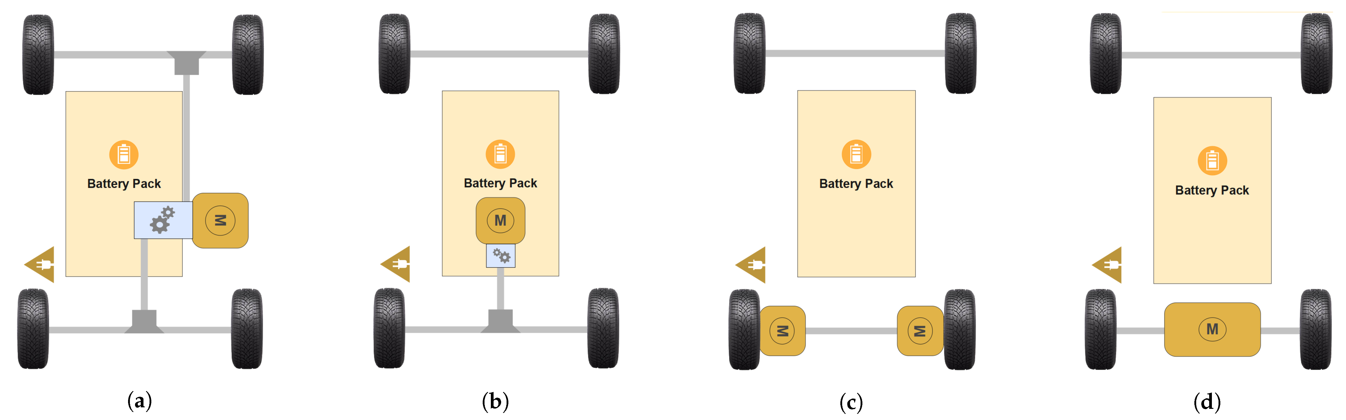
2.5. Different Types of Electric Drivetrain Typologies

There are four common electric drivetrain typologies for electric vehicles: full battery EV, hybrid EV plug-in hybrid EV, and fuel cell EV. The choice of typology depends on the user’s specific requirements and the original behaviour of the vehicle. It is crucial to consider both the complexity of the implementation and the suitability of each drivetrain typology for the user’s particular vehicle use case. Factors such as range, component accessibility, and infrastructure requirements are important in this decision-making process. One can determine the most suitable electric drivetrain typology by carefully assessing these aspects. Due to the lack of electric vehicle infrastructure in sub-Saharan Africa and the complexity of retrofitting a minibus taxi, the method proposed in this article consists of a battery EV drivetrain typology.
A battery EV drivetrain consists of one or multiple electric motors and possibly single- or multi-speed transmissions powered by a single large battery pack. The drivetrain does not include any ICE or onboard charging sources. The battery pack is charged using an external power source. Figure 3 shows the most common drivetrain typologies for a retrofit.
One option for retrofitting when the original ICE vehicle is a four-wheel-drive vehicle is shown in Figure 3a. Here, the electric motor and a proposed reduction gearbox can be connected to the transfer case to maintain the four-wheel-drive capability. On the other hand, Figure 3b shows a more familiar and straightforward retrofit typology. It involves a single electric motor with a reduction gearbox connected to the rear axle differential using a custom prop shaft. This method is widely used due to its simplicity and ease of implementation, as it mimics the behaviour of an ICE vehicle’s drivetrain [22,23].
An alternative drivetrain configuration is shown in Figure 3c, which features two in-wheel hub motors. These motors are highly efficient; however, their high cost, customisation requirements, and the need for additional bodywork make them complex and less desirable for retrofit scenarios [24]. However, they allow precise torque control over each wheel compared to the lack of wheel-torque control in the other typologies.
Figure 3d shows a complete axle motor, replacing the entire rear axle of the ICE vehicles and directly connecting to the two rear wheels of the vehicle with two shafts. A similar motor can be used for front-wheel-drive vehicles. These motors commonly include an internal reduction gearbox, simplifying the implementation process. However, they require more modifications, additional bodywork, and the replacement of the entire rear axle, which increases the homologation complexity of retrofits.

2.6. Battery Electric Vehicle Component List

As mentioned, the chosen drivetrain typology for the presented use case utilises a single electric motor with a reduction gearbox connected to the rear differential gearbox, as illustrated in Figure 3b. Several compelling reasons support this drivetrain selection. In addition to being a cost-effective solution compared to other drivetrain typologies, two additional considerations support this choice. First, it offers ease of implementation, as it involves a straightforward connection between the electric propulsion unit and the existing differential gearbox. A propeller shaft is required because it is impossible to connect the electric motor and reduction gearbox to the differential by just bolting it on. The motor should also not move with the rear axle; therefore, a propeller shaft is used to adapt to the rear-axle vibrations. Second, this typology eliminates the need for body modifications, as the existing mounting brackets and holes underneath the vehicle can be utilised. Given these advantages, the single motor with a reduction gearbox configuration is the most suitable option for establishing a battery EV drivetrain for the specific use case presented in this study.
To design and select components for the proposed battery EV drivetrain, the following components need to be investigated:
  • Electric motor: The electric motor replaces the ICE of the original vehicle.
  • Reduction gearbox: For safety reasons, it is crucial that the new electric propulsion unit replicates the original rpm (revolutions per minute) and torque ranges produced by the transmission and ICE due to the components from the differential gearbox to the wheels being unchanged. The reduction gearbox ensures that the high rpm speeds generated by the electric motor do not exceed dangerous limits that the original vehicle’s components are not designed to handle. Additionally, the reduction gearbox substantially increases the torque that can be produced by the electric motor, enabling the vehicle to maintain adequate performance and provability similar to the original ICE configuration.
  • Inverter: The inverter acts as the motor controller by converting the DC input power from the battery pack to the desired AC or DC output power, depending on the motor specification and desired operation.
  • Battery pack: The battery pack of the electric vehicle is a combination of battery cells, often lithium ion, combined in specific configurations (series and parallel) to achieve a predetermined energy capacity in kWh and the desired voltage for the chosen inverter. Battery packs include battery management systems (BMS) to ensure that each cell is monitored and balanced to maximise usability and lifespan.
  • Charging system: The charging system consists of an onboard charging port and charger. The system allows the battery pack to be charged from an external power source.
  • Cooling systems: Two central cooling systems can be implemented in a retrofit vehicle. There is one cooling system for the battery pack to keep the battery cells operating at the most efficient temperature. Similarly, there is a cooling system for the electric motor.
  • DC-DC Converter: The converter must supply (12 V to 48 V) to the low-voltage system in the vehicle from the high-voltage battery pack. The low-voltage system will power all the 12 V systems in the vehicle, such as the headlights, windscreen wipers, indicators, and various vehicle electronics.
  • Vehicle control unit (VCU): The VCU acts as the central communication hub for the various components and electronic control units (ECUs).
  • Electric throttle control: If the original ICE vehicle uses a manual throttle cable, it will need to be replaced with an electronic control throttle that connects to the VCU for acceleration control.
  • Electric servo pumps: If the original ICE vehicle contained an engine-powered assisted hydraulic pump for the power steering and brakes, one or two electric servo pumps need to be implemented in the retrofit to assist with power steering and the hydraulic pressure for the brakes.
  • High-voltage safety components: Specific high-voltage (60 V to 800 V) safety components are required for the battery EV high-voltage system, such as high-voltage wiring, fuses, and safety disconnects.

3. Methodology

This section describes the retrofit design process, which includes the sizing and selection of the main components described in Section 2.6 for a specific ICE vehicle. These components include the electric motor, reduction gearbox, battery pack, inverter, and VCU. The design and selection process follows the golden rule of maintaining the original specifications of the ICE vehicle, including the weight restriction calculated in Section 2.4.

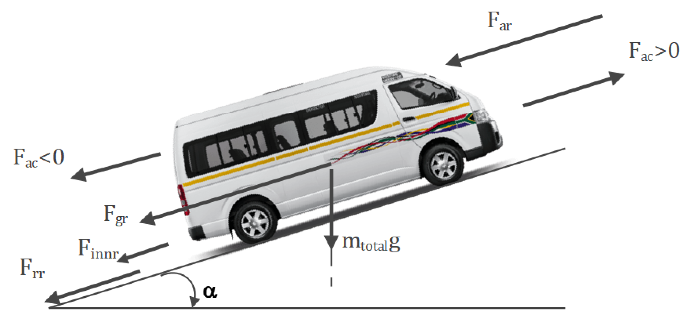
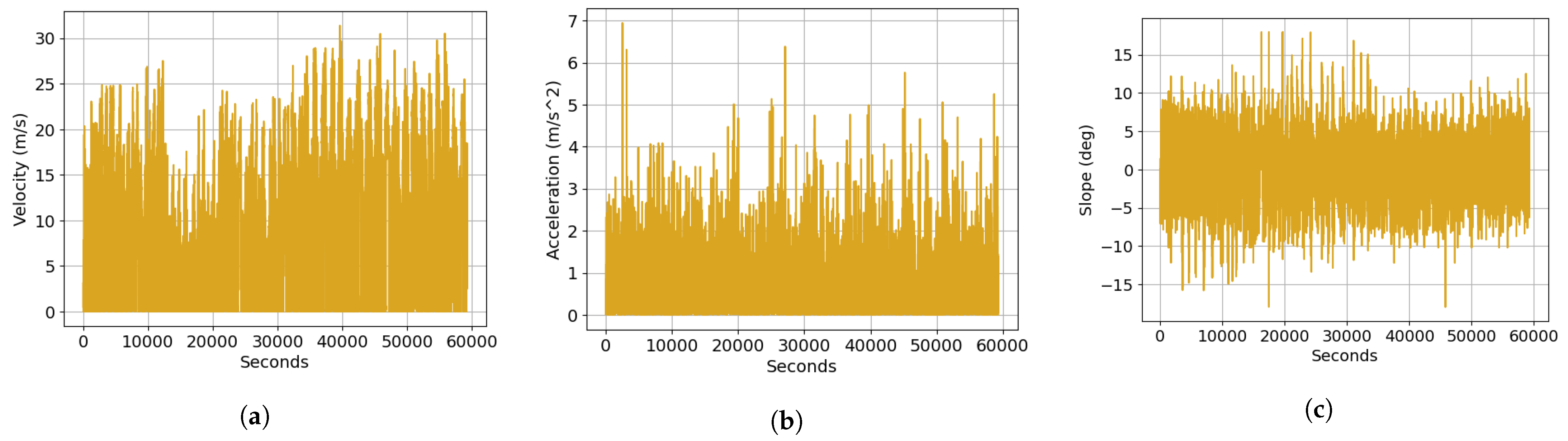
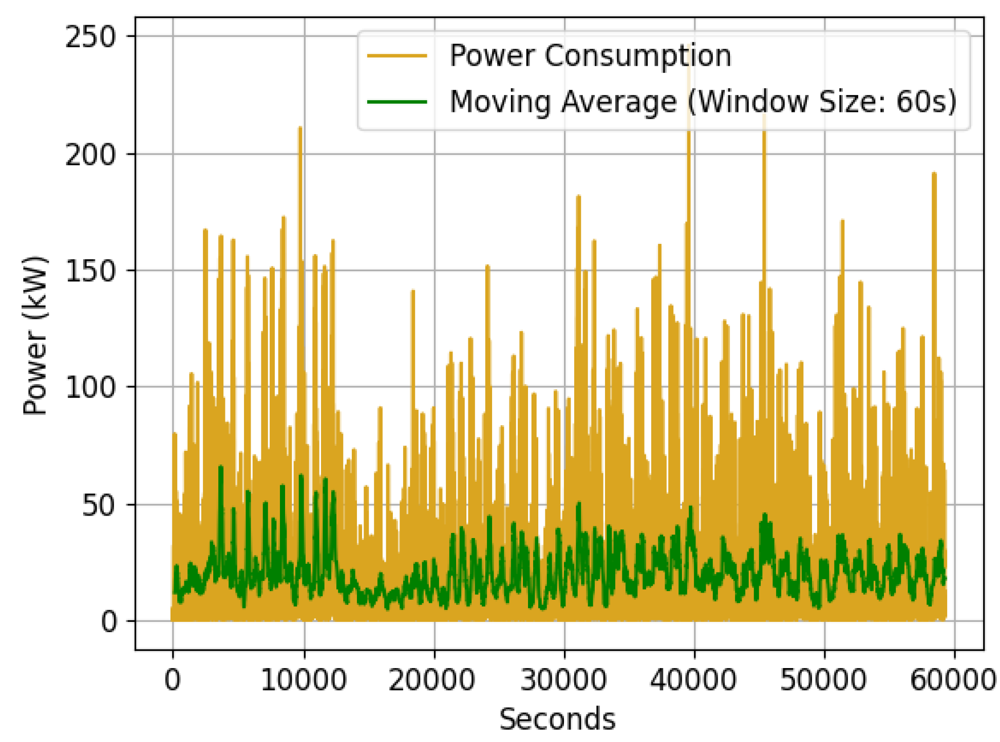
3.1. Vehicle Driving-Cycle Power Requirements

To understand and establish the original vehicle requirements and specifications, driving-cycle measurements can be used. These driving-cycle measurements are typically obtained using GPS data from the ICE vehicle. However, while tracking data usually consist of low-frequency (one-minute) or origin-and-destination data, the drive-cycle data need to include measurements of location, speed, and acceleration. Moreover, they must be captured at a high-enough frequency to adequately represent the energy transitions apparent in mobility [25]. A micro-mobility simulator can be used to interpolate low-frequency or origin-and-destination data, but care is required to ensure a representative simulation setup [12].
The high-frequency driving-cycle data (1 sample per second) consist of GPS data collected from six tracking devices to analyse the micro-mobility behaviour of Toyota Hiace Ses’fikile minibus taxis, recording information such as the velocity and elevation, with the elevation data sourced externally. The devices also calculated the displacement and slope angle. Data were collected on three route types (urban, hilly, inter-city) and at three times of the day (morning, afternoon, and evening) for 62 trips over the three different routes located in Stellenbosch, South Africa.
The high-frequency driving-cycle data can be used to determine the torque and speed requirements for the specific use case based on the ICE vehicle’s mobility. Separately, after the design, this drive-cycle data are eventually used to simulate the electric drivetrain using a vehicle kinetic model [19].
In the absence of driving-cycle data, a crude approximation can be made in which a constant vehicle cruising velocity and an acceleration rate to reach that velocity within 25 s, as well as an average incline road slope of 10 degrees, are assumed. Table 1 presents the constant values that can be used for a vehicle cruising velocity of 16.6 m / s .
To determine the maximum power required for the vehicle’s drivetrain to propel the vehicle forward, a kinetic model of the vehicle is employed to calculate the total tractive power [25,26]. Figure 4 shows an external kinetic force diagram. This analysis was performed using a specific drivetrain efficiecny methodology designed for this purpose. This approach enables an accurate assessment of the power demands of the vehicle’s drivetrain and ensures that the electric propulsion unit provides sufficient power to meet the vehicle’s performance requirements.
The total tractive force, F tr , for every data point shown, n, acting on the vehicle, as shown in Figure 5, is determined using Equation (2).
F tr [ n ] = F ac [ n ] + F rr [ n ] + F ar [ n ] + F gr [ n ] + F innr [ n ]
where F ac is the acceleration force, F rr is the rolling resistance, F ar is the aerodynamic resistance, F gr is the gradient resistance, and F innr is the inertia resistance of the axle and propeller shaft. These values are calculated using Equations (3)–(7):
F ac [ n ] = m total a [ n ]
F rr [ n ] = C r m total g cos ( α [ n ] )
F ar [ n ] = 1 2 ρ air A C d ( v [ n ] ) 2
F gr [ n ] = m total g sin ( α [ n ] )
F innr [ n ] = 1 r w 2 J axle ω ˙ w [ n ] + 4 J w ω ˙ w [ n ]
The vehicle with a weight of m total , uses dynamic variables such as the vehicle acceleration, a ; vehicle velocity, v; angular acceleration of the wheel, ω ˙ ; and rode slope, α , which are specific to the driving cycle of the vehicle.
The use case presented in this paper uses driving-cycle data recorded for a Hiace Ses’fikile taxi in Stellenbosch, South Africa [25]. Table 2 lists the parameters of the Toyota Hiace Ses’fikile minibus used as the use case in this paper.
The driving cycle is employed due to the inherent trade-off between the vehicle velocity, acceleration, and slope. Using solely the maximum values of each variable to calculate the maximum power would lead to an overestimation and oversizing of the electric motor.
Figure 6 displays the percentages associated with each force component of the total force over the entire driving cycle acting on the minibus, calculated using Equation (2). The graph illustrates that due to the minibus operating at a lower speed, the primary force that must be overcome during the driving cycle is rolling resistance.
Figure 5 shows the velocity, acceleration, and slope recorded in the tracked driving-cycle data.
To establish the power required to maintain the dynamics of the vehicle, we use Equation (8) to calculate the required power, P req [ n ] , of the vehicle for every tracking data point shown in Figure 5.
P req [ n ] = F tr [ n ] × v [ n ] 1000
The power for every second and the moving average power curve for every minute are shown in Figure 7.
Once the vehicle’s power requirements are determined, we proceed to compute the necessary torque and speed requirements, T prop [ n ] and n prop [ n ] , respectively, that the electric propulsion unit (comprising the electric motor and reduction gearbox) must deliver using Equations (9) and (10).
T prop [ n ] = r w ( F tr [ n ] ) ( i dt × μ dt )
n prop [ n ] = 60 × v [ n ] × i dt × μ dt 2 π ( r w )
The gear ratio of the drivetrain, denoted as i dt , encompasses the gear ratio of the differential gearbox, along with any other potential gear ratios within the original drivetrain. The efficiency of the drivetrain, μ dt , must also be considered in the equations. These equations are used to plot Figure 8 for every driving-cycle data point, using the values shown in Table 3. The gear ratio of the drivetrain is the gear ratio of the original differential gearbox of the ICE vehicle.
By analysing the information presented above and considering that the recorded high-fidelity tracking data reflect behaviour similar to that of an internal combustion engine and not that of an electric vehicle, a detailed examination of the moving averages of the power consumption, as shown in Figure 7, and the torque, as shown in Figure 8a, can be used to establish the propulsion unit design requirements. The GPS data, recorded at one-hertz intervals, can exhibit irregularities owing to the unique driving characteristics inherent to internal combustion engine (ICE) and gearbox-driven vehicles. In these cases, sudden and pronounced changes in acceleration, commonly found in ICE vehicles, result in high levels of jerk in the 1 Hz data. To address this, we apply a low-pass filter, which effectively smooths these abrupt changes in driving behaviour while preserving the overall energy profile. This ensures that the power requirements are based on a more representative and smoother driving pattern, which is comparable to what would be expected in an electric vehicle (EV). Taking this into account and evaluating the aforementioned figures, we establish the design requirements for the propulsion unit, which are outlined in Table 4.
Table 4 shows that the maximum values required for the electric motor are lower than certain maximum values found in the tracking data, as depicted in Figure 8. This discrepancy can be attributed to the ability to confidently eliminate outliers in the data, given its high tracking rate of 1 s per data point. This resulted in scenarios of instantaneous high power and torque demands, which fall significantly below the maximum outliers when averaged out. As a result, the selection of maximum design values is a balanced approach, incorporating an assessment of the moving average to ensure that the electric motor can consistently provide power and torque demands over extended time frames.

3.2. Propulsion Unit Selection and Sizing Model

The propulsion unit for the proposed electric drivetrain can consist of either a single electric motor or a combination of an electric motor and a single-speed reduction gearbox.
When comparing electric motor types for electric vehicle applications, various technical concerns, as discussed in [30], contribute to the superiority of permanent magnet synchronous motors in specific criteria compared to direct current motors, induction motors, and switched reluctance motors [31,32]. A comprehensive comparison of each motor, considering the technical attributes outlined in [33,34] is provided in Table 5. The motors are assessed in relation to one another using a ranking system from 1 to 4, where 1 signifies the most favourable performance and 4 indicates the least favourable. The motor with the lowest cumulative ranking is considered superior in this context.
Regarding the information in Table 5, the permanent magnet synchronous motor emerges as the most suitable choice for the retrofit case, primarily due to its power density and efficiency characteristics. These attributes are critical in a retrofit case to meet the golden rule requirements.

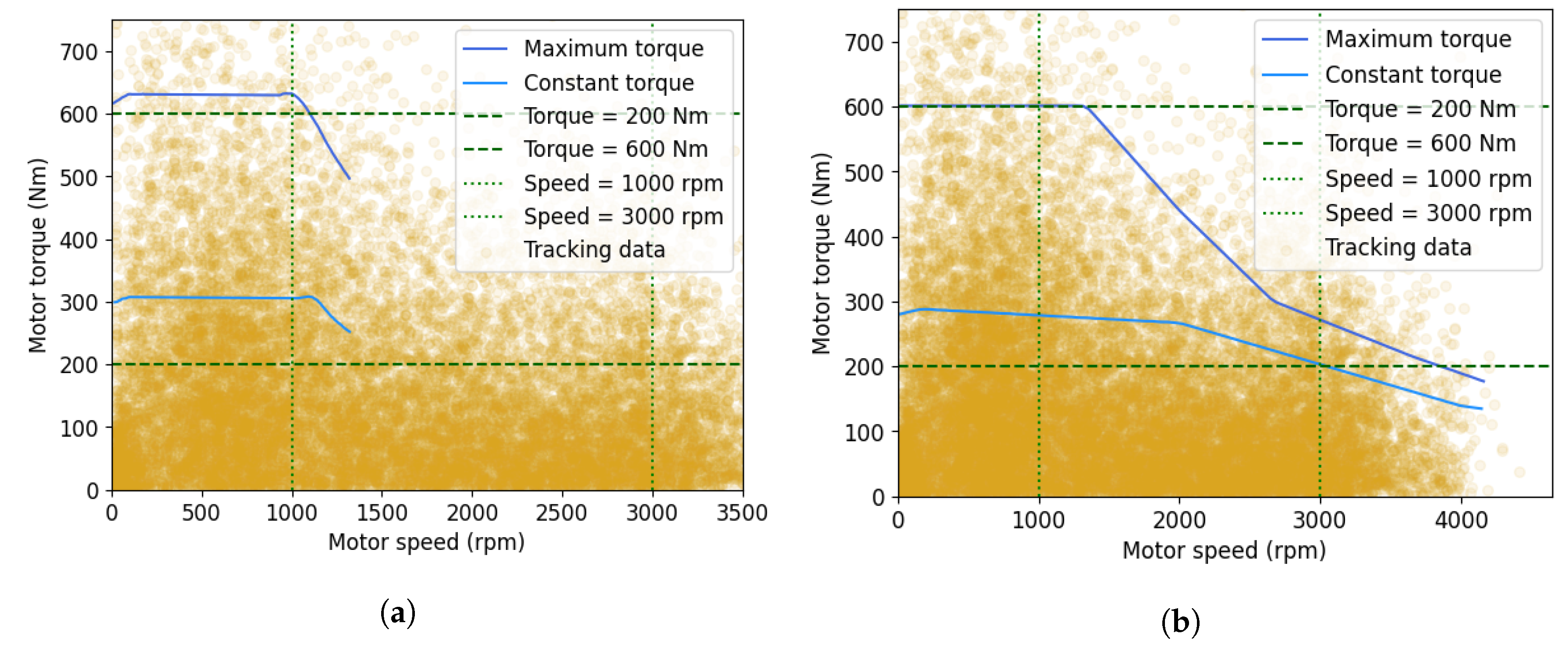
3.2.1. Propulsion Unit Torque-Speed Analysis

The selection of a propulsion unit, whether a singular electric motor or a combination of a reduction gearbox and electric motor, necessitates a comparison of the torque-speed characteristic curves of potential electric motors to the data tracked on the internal combustion engine vehicle, as shown in Figure 9. This analysis is crucial for a direct comparison against the design requirements specified in Table 4 and presented in Figure 9a using vertical and horizontal lines.
In Figure 9a, we can pinpoint potential permanent magnet synchronous motors aligning with torque and speed requirements. Within this article, we introduce three viable options for the minibus. The objective of these choices is to demonstrate the utilisation of a sole electric motor for propulsion and how appending a reduction gearbox can result in a smaller motor while fulfilling speed and torque needs. The chosen three motors’ distinctive design characteristics are outlined in Table 6.
As evident in Table 6, these permanent magnet synchronous motors largely satisfy the design requirements in terms of power and motor speed. Nevertheless, a brief evaluation of the parameters listed in Table 6 against the established requirements allows for an initial motor screening. A more thorough analysis of the torque-speed characteristic curve for each motor is essential. Consequently, the speed-torque characteristic curve for each motor should be compared against the designated design criteria in Figure 9a.
When considering the torque and speed, it is evident that the Cascadia motor’s torque-speed characteristic curve, as shown in Figure 9d, is the only curve that aligns with the designated torque-speed criteria. Nevertheless, an assessment of the torque-speed curve highlights the motor’s specific design for high-torque applications at low speeds, featuring a substantial initial torque that sharply diminishes with increasing vehicle rpm. Given the stipulated nominal speed of 1000 rpm, extended operation beyond this base speed, within the field-weakening region, should be avoided. Operating in this region necessitates elevated phase currents to reduce the torque while maintaining constant power, leading to thermal efficiency and physical implications [38]. The motor’s cost is nearly four times that of the other motors, necessitating careful consideration, despite its streamlined implementation, which eliminates the need for additional components to fulfil the propulsion unit requirements.
Figure 9 shows the torque-speed characteristics without a reduction gearbox. When assessing the Emrax motor (Figure 9b), it is evident that it meets the speed requirement but not the torque requirement. The Emrax motor maintains steady torque across rpm, an advantage over other motors that require field weakening. The Bosch motor has a wider rpm range but it falls short in terms of torque. A reduction gearbox with an optimal ratio is introduced for both motors to solve this issue. The results are presented in Figure 10.
Figure 10a indicates that the Emrax motor meets the torque requirement with a reduction gearbox but the rpm range decreases significantly, rendering the combination inadequate for the propulsion unit. In contrast, the Bosch motor, in conjunction with the reduction gearbox, satisfies the torque-speed requirements. Hence, considering torque-speed characteristics, the Bosch propulsion unit best suits the Hiace Ses’fikile drivetrain proposal.

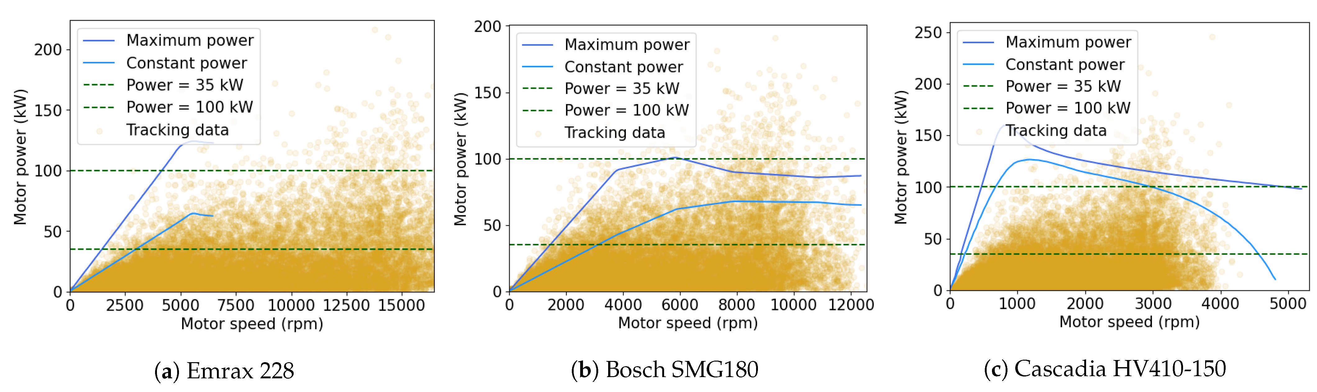
3.2.2. Propulsion Unit Power Analysis

Another pivotal aspect to consider in sizing an appropriate propulsion unit is the power characteristics of the motors. Power is the rate at which the energy/work is transferred from the propulsion unit to the wheels. To facilitate this analysis, consider that the power generated by the propulsion unit equals the product of its torque and angular velocity produced, as expressed by Equation (8). Notably, the gear ratios in the drivetrain do not impact power, as changes in the gear ratios lead to proportional torque and rpm adjustments, maintaining consistent power output. Therefore, to assess whether the proposed three propulsion units satisfy the calculated vehicle power requirements, we evaluate each motor in tandem with its respective reduction gearbox and without the reduction gearbox in the case of the Cascadia motor. Consequently, the power versus speed requirements of the vehicle, calculated using Equation (8), are graphed and imposed onto the power curves of each motor in Figure 11. The horizontal lines indicate the design power requirements for the propulsion unit in Table 4.
Figure 11a illustrates that even with the utilisation of the gear ratio in conjunction with the motor, the Emrax motor fails to meet the rpm requirements and cannot generate the necessary power. Conversely, the Bosch assembly depicted in Figure 11b adequately meets the power demands and is capable of delivering both the maximum and nominal power required by the vehicle over the range of rpms.
On the other hand, as illustrated in Figure 11c, the Cascadia motor exhibits an oversize for the intended application, displaying nominal power and significantly surpassing the maximum power requirement. Exceeding the motor’s power output beyond the required levels can accelerate battery drain due to the higher current drawn to generate adequate power at lower rpms.

3.2.3. Propulsion Unit Selection

Considering the preceding analysis, the Bosch SMG180 motor coupled with the electric single-speed reduction transmission, Bosch EDT180 [39], emerges as the optimal choice for the intended use case. The single-speed transmission has a weight of 17 kg, resulting in a total propulsion unit weight of 47 kg. This is much lighter than that of the original propulsion unit of the minibus, which had a combined weight of 235 kg for the petrol engine and five-speed manual transmission.
In combination with motor selection, the appropriate inverter must be chosen. This component governs the power exchange between the battery pack and the motor. The inverter transforms the direct current generated by the high-voltage battery pack into an alternating current, facilitating motor operation. Moreover, it regulates the current frequency, enabling torque and speed control of the electric motor. Communication between the inverter and the VCU is established through a vehicle communication protocol called a controller area network (CAN) connection. Most commercial off-the-shelf electric motors are sold as a set, with an inverter designed for the specific unit. For the Bosch SMG180 motor, the Bosch Generation 4 inverter [40] is the recommended choice. However, when a motor-specific inverter is absent, the parameters listed in Table 7 should be assessed to match an inverter with the motor to ensure compatible voltages, currents, and power.
Since the power input to the motor is the product of the voltage and the current, the power input to the motor can be adjusted by manipulating the voltage and current supplied to the motor by the inverter. Consequently, increasing one of these parameters can lead to higher power output within certain limits, as discussed in Section 3.3. One approach involves expanding the battery pack size to increase the voltage. This strategy has the added benefit of reduced current draw from the battery pack. Avoiding higher current draw minimises issues like increased heat generation, I 2 R - power losses, and the necessity for higher-rated wiring.

3.3. Battery Size and Range Determination

The vehicle’s battery pack design is dependent on several critical parameters. These encompass the battery pack output voltage and the anticipated capacity. The voltage specification is contingent upon the input voltage range dictated by the chosen propulsion unit inverter. The battery pack’s capacity and voltage are determined by a combination of multiple battery cells in series and parallel.

3.3.1. Battery Technology and Cell Selection

The initial phase involves the selection of appropriate battery cells for composing the battery packs. The chosen battery cell’s chemistry assumes significance, given the energy density (Wh/kg) and lifecycle attributes. The lifecycle indicates the number of complete charging cycles at a specific discharge depth that a battery can undergo before its depletion (80% depth of discharge). The main battery chemistries evaluated in the literature include nickel metal hydrate (NiMh), lead acid (Pb-PbO2), sodium nickel chloride (NaNiCl), nickel cadmium (NiCd), zinc bromide (ZnBr2), various lithium-ion chemistries, sodium sulphur (NaS), and solid state [41,42].
The current literature highlights the energy density and lifecycle characteristics behind the use of lithium-ion batteries in the majority of electric vehicles. In terms of retrofitting, lithium batteries offer notable advantages, such as a reduced battery pack weight due to their superior energy density and an extended battery life. Incorporating these factors alongside cost considerations explains why lithium-ion batteries are the prevailing choice in electric vehicles [43]. Solid-state batteries, a relatively recent technology, present challenges in terms of high manufacturing complexity and cost. Consequently, the deployment of electric vehicles equipped with such batteries is anticipated to begin only after 2025 [44].
Presently, there are five primary types of lithium-ion battery configurations: lithium nickel cobalt aluminium (NCA), lithium nickel manganese cobalt (NMC), lithium manganese oxide (LMO), lithium titanate oxide (LTO), and lithium iron phosphate (LFP) [45]. NCA and NMC compositions are favoured primarily due to their elevated energy density and extended life cycle. NCA offers higher energy densities, which lead to longer-range options for vehicles but are more susceptible to thermal runaway compared to NMC. Meanwhile, LFP boasts superior overall safety compared to NCA and NMC, with a marginal performance reduction [45]. For the proposed use case, an LFP cell by Contemporary Amperex Technology Co. Limited (CATL) is adopted, featuring the characteristics outlined in Table 8 [46].

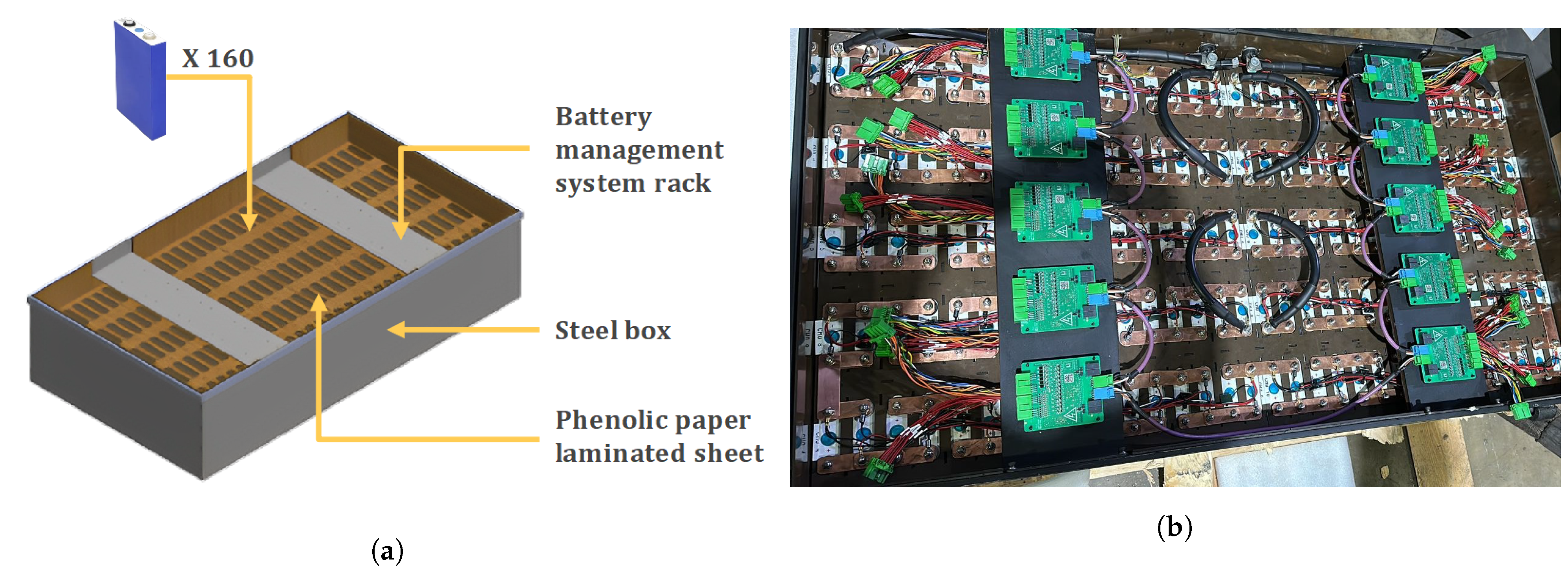
3.3.2. Battery Pack Design

Based on the chosen cells, we can proceed with designing and assembling the battery pack for the retrofit vehicle. The initial step involves defining three vital design prerequisites for the battery pack.
Firstly, we establish the estimated weight of the battery pack, including the frame, wiring, and all associated components. This can be estimated using the equation and process outlined in Equation (1). Notably, the estimated weight of the components extracted from the minibus amounts to approximately 450 kg. The weight of all components within the designed retrofit powertrain, excluding the battery pack, is approximately 80 kg. As a result, there is a remaining weight allowance of approximately 370 kg to conform to weight constraints.
Moreover, the minibus is required to attain a minimum range of 100 km on a single full charge. This range design requirement is dictated by cost considerations and the fact that this is a proposed prototype minibus. However, in future iterations, larger ranges can be designed. Drawing from data on present light electric vehicles on the road, their efficiencies span from 0.1 kWh/km to 0.9 kWh/km [47,48].
The efficiency of retrofit vehicles tends to be lower than newly constructed vehicles. The reason for this is twofold: retrofit vehicles tend to be older and not designed to reduce drag, and they tend to have unnecessary legacy components—predominantly mechanical—that contribute to inefficiencies.
For the minibus taxi scenario, we assume an efficiency of 0.51 kWh/km [25]. Utilising Equation (11), this yields an estimated battery pack capacity of 51 kWh.
Capacity = range × energy efficiency
Lastly, the battery pack’s voltage is designed to align with the input voltage range stipulated in Table 7. This design choice aims to maximise the voltage to limit the current, thereby mitigating the risk of thermal runaway. For the specific use case, the voltage is set between 200 and 400 V.
Multiple cells connected in series form a single module, which can then be connected in parallel with other modules to create a battery pack that meets the above-mentioned requirements.
Capacity = nominal voltage × electric charge × number of cells
Applying Equation (12) at an operating temperature of 30 degrees Celsius, with a battery pack capacity of 51 kWh, a nominal voltage of 3.2 V, and an electric charge of 105 Ah, we find that 152 cells would be required. In this specific use case, 160 cells are utilised. However, connecting all 160 cells in series would result in a voltage of 512 V, which exceeds the motor’s specification. To mitigate this, the 160 battery cells are divided into 80 pairs. Each pair is connected in parallel to form a 3.2 V, 210 Ah pair cell. Connecting all 80 pairs in series yields a combined nominal voltage of 256 V. The merging of these two modules in parallel yields the battery pack parameters shown in Table 9.
Notably, during the design of battery boxes, it is important to consider that the box can be segmented into various combinations of series and parallel connections. This flexibility is crucial for fitting the box into different locations within the vehicle based on its specific layout requirements.
To ensure safety and compliance with additional component requirements, the battery pack must be enclosed within a protective box. The design of this enclosure is shown in Figure 12.
Of particular significance is the inclusion of phenolic paper laminated sheets, which are strategically positioned over all the battery cells to provide insulation and an additional layer of safety against potential short circuits. These sheets are also inserted between each battery cell, adding an extra level of protection to the arrangement.

3.3.3. Battery Pack Additional Components

To complete the assembly of a fully functioning battery pack, the following list of components should be included to ensure safe and efficient operation:
  • Battery cells: As explained in Section 3.3.1, the battery cell selection is critical for the performance and safety of the battery pack.
  • Battery Management System (BMS): The battery management system encompasses several crucial functions such as monitoring, protection, charging and discharging management, communication, diagnostics, and data management. The BMS plays a pivotal role in maintaining the balance of the battery pack and controlling voltage levels [49]. This system is divided into two key sub-components: the BMS master and the BMS slaves. The BMS master handles back-end operations and is situated within the vehicle’s electronic control unit. Conversely, the BMS slaves are microcircuits linked to the front-end connections of the battery cells [50]. Each BMS slave can be linked to multiple battery cells and carries out essential tasks such as signal acquisition, filtering, and more.
  • Cooling management system: The majority of battery packs require a cooling management system to maintain batteries within an optimal temperature operating range. In this use case, a battery pack cooling system was not implemented. This may lead to operational temperatures that exceed optimal cell temperatures, which can result in inefficient battery operation. To ensure safe temperature ranges, the charging and discharging rates were limited operationally in accordance with manufacturer specifications.
  • CAN communication system: For effective communication between the VCU and the battery pack, it is crucial for the battery pack to feature CAN outputs. These outputs enable seamless communication between the VCU and the BMS slaves.
  • High-voltage wiring: The battery pack is connected to the inverter via HV wiring, which should be able to withstand the expected maximum current. This is determined by the motor’s power and the battery pack’s voltage. In the proposed battery pack, the wire should be able to withstand currents of up to 300 A.
  • Busbars and connectors: Busbars are reliable metallic strips used to connect the different cells, and various other standard electric connectors can be used to connect to the input and output plugs.
  • Fuses: Fuses are added in between the battery packs to prevent current-overload and short-circuit scenarios. The fuses added to the battery pack are rated at 300 Amp and 400 V DC.
  • Isolation contactors: An isolation contactor functions as an electrical switch connecting the battery pack to the remainder of the vehicle. This mechanism enhances safety during maintenance activities and safeguards against potential emergencies. The VCU of the vehicle controls the contactor.
  • Manual disconnect: The manual disconnect is a manual switch that disconnects the main power connection from the battery box. This is used to isolate power in the case of emergencies or maintenance operations.

3.4. Vehicle Electric and Electronic Systems

The process of retrofitting a vehicle involves the integration and interconnection of various electronic components, including the VCU, BMS, charger controller, and original vehicle harness. These are then combined with electric powertrain components like the electric motor, inverter, charger units, and battery pack. For the provided use case, a connection schematic of the retrofitted minibus is illustrated in Figure 13.

3.4.1. Vehicle Control Unit

The VCU’s main role is to facilitate communication between all the components within the electric powertrain through controller area network (CAN) bus connections. The CAN bus system was developed to ensure fast and dependable communication between the various components in a vehicle’s powertrain. This system has stood as the industry standard in automotive technology. The VCU communicates with the powertrain components using the CAN bus. In the specified use case, the VCU uses a DSEM640 programmable controller [51].
The controller has Ethernet, USB, CAN, and configurable I/O connections. In the context of the original harness, the appropriate connections should be routed to the correct inputs of the ECU. Additionally, all new components should also be properly linked to the controller.
The controller consists of flexible user programming via the CODESYS 3.5 software development environment.

3.4.2. High-Voltage Source

The high-voltage (HV) source stems from the 256 V battery pack, functioning as the vehicle’s power supply. The voltage lines are designed to manage up to 300 A of current flow. To ensure the safety of the components, 300 A/400 V fuses are integrated between the battery pack and other HV lines, limiting the current beyond the designated limits. This HV supply energises the electric motor/generator through the powertrain’s inverter.
The Bosch Generation 4 inverter comprises two primary converters. The DC-to-AC converter transforms the input DC voltage from the battery pack into AC voltage to drive the electric motor. Conversely, this inverter converts AC back to DC when the motor operates in generation mode during recuperation. Furthermore, the inverter is equipped with an integrated DC-to-DC converter, which is responsible for transforming the HV supplied by the battery into power for the 12 V low-voltage systems.
The charger controller interfaces with a 230 VAC input charging port, capable of accommodating a charging power of up to 22 kW. The received AC voltage from the charging port is also converted to DC voltage via the powertrain’s charging controller.
To address safety concerns, an HV rack is implemented to aggregate and centralise all electric and communication connections for the various HV components. Each connection within this HV rack is safeguarded by a 12 V contactor, which is linked to the VCU and powered by the low-voltage system. These contractors switch and disconnect the HV line and are controlled via CAN signals from the VCU. In the minibus case, the BMS-master is also connected to the HV rack due to space convenience but can also be connected to the LV rack if space permits it.

3.4.3. Low-Voltage Rack

The low-voltage (LV) rack serves as a central hub for connecting all low-voltage power lines and their corresponding communication lines. Keeping in mind the golden rule for retrofitting, most of the original vehicle’s LV connections are reused, excluding those directly linked to the engine. This strategy guarantees that all vehicle functionalities, including the vacuum pump, water pump, indicators, headlights, sensors, and other low-voltage subsystems, remain operational as they originally were. Additionally, the LV rack facilitates the addition of new low-voltage lines required for new LV components added to the electric powertrain.
The LV rack is powered by a lead–acid battery. This design ensures that the LV components continue to function, even if the primary battery power source is cut off, as with a combustion engine power source. Power is supplied from the inverter, connected via the LV rack, to charge the 12 V battery.
The LV rack works in conjunction with the VCU, providing the necessary 12 V power supply to all the LV components within the vehicle. Ensuring the use of appropriate fuses throughout the LV rack is pivotal for ensuring the safety of the components. For instance, a 1 Amp fuse can be employed for the ignition, whereas a 3 Amp fuse can be utilised for the power line leading to the vehicle’s VCU.
The LV rack comprises four distinct relays, enabling power control between the VCU and the LV components. These four relays control the reverse operation, servo pump, vacuum pump, and water pump. This enables the VCU to activate and deactivate these components as required based on driver inputs. The servo pump is a unique addition to the electric powertrain and is introduced to assist with power steering. The vacuum pump is for the brakes discussed in Section 4. The water pump is used to deliver coolant to the electric motor and forms part of the thermal system.
The 12 V system powers the following components: ECU power, reverse relay, water pump, servo pump, vacuum pump, dashboard screen, speed sensor, inclination sensor, gear switch unit, and coolant level sensor.

4. Braking System and Regenerative Braking

The retrofitted minibus employs a vacuum-based brake system for braking in conjunction with regenerative braking [52]. A key feature of this system is the utilisation of an electric vacuum pump, which generates a vacuum within the brake booster to enhance braking efficiency. As mentioned earlier, the vacuum pump is integrated into the LV system of the vehicle. The lead–acid battery serves the purpose of storing power for the LV system, ensuring that the brakes remain operational, even if the HV battery is depleted. In the unlikely scenario where the vacuum pump is non-operational, the brakes can still function normally without assistance, although they might need more force from the driver to generate adequate braking force.
In parallel with the vacuum-based brake system, the vehicle also incorporates regenerative braking, also known as recuperation. Regenerative braking operates by leveraging the momentum of the vehicle when the motor is not propelling it, causing the electric motor to transition into an electric generator [53]. The reverse torque exerted by the motor slows down the vehicle. Meanwhile, the inverter harnesses this generated power to recharge the battery. The degree of regeneration can be fine-tuned using the VCU of the vehicle, which is directly correlated to the vehicle deceleration and is even capable of bringing the vehicle to a complete stop at a specific torque rate.
The mechanical hand brake continues to function as it did originally in the minibus. A critical safety aspect involves the VCU of the vehicle monitoring both the vacuum pump and the regenerative braking system. This vigilance ensures that essential safety indicators and functions are duly activated in case of vacuum or regeneration system failures. However, as previously mentioned, the brakes remain functional even without the vacuum pump, and the hand brake retains its normal operation.

5. Conclusions

This paper outlines a scientific roadmap for the transformation of internal combustion engine vehicles into electric vehicles (EVs). The delineated process encompasses intricate steps, including the systematic disassembly of internal combustion engine vehicles, meticulous adherence to homologation requirements and regulatory standards, and the methodical selection and design of crucial components. These components encompass the entire spectrum, ranging from the propulsion unit and battery pack to the intricate electrical and electronic systems, culminating in a vital braking system.
One of the pivotal results achieved in this study is the establishment of precise power, torque, and speed requirements derived from high-fidelity driving-cycle data. These specifications serve as the cornerstone for the retrofitting process, ensuring that the converted EV aligns closely with the performance characteristics of its internal combustion engine predecessor.
Furthermore, a clear and systematic component selection process was meticulously presented. Every selected component underwent rigorous validation through the development of a real-life prototype. This tangible validation not only underscores the viability of the proposed methodology but also highlights its applicability in practical scenarios.
A tangible and illustrative use case is presented using a Toyota-manufactured Hiace Ses’fikile taxi, a cornerstone of the southern African paratransit industry. This case not only serves as validation of the proposed approach but also highlights the practicality and importance of converting internal combustion engine vehicles into EVs. This endeavour plays a pivotal role in equipping southern Africa with the skills and knowledge needed to embrace the transition towards electric mobility.
Looking ahead, future research endeavours will further refine and optimise the conversion process. This may involve enhancing the methodologies for component selection and exploring cutting-edge technologies to bolster efficiency and performance, with special attention given to areas such as the cooling system in retrofit vehicles. These developments are pivotal in advancing the field of EV retrofitting and aligning sub-Saharan Africa with the evolving landscape of sustainable transportation.

Author Contributions

S.L.: Methodology, software, formal analysis, investigation, writing—original draft preparation, data curation and visualization. A.A.d.P.: Formal analysis, validation, writing—review and editing and supervision. M.J.B.: Conceptualization, formal analysis, validation, writing—review and editing, supervision and funding acquisition. All authors have read and agreed to the published version of the manuscript.

Funding

This research was funded by the South African National Energy Development Institute (SANEDI) and Golden Arrow Bus Services (GABS).

Data Availability Statement

Data available on request.

Acknowledgments

The authors would like to extend their gratitude to the South African National Energy Development Institute (SANEDI) for its substantial financial support of the retrofit project and Rham Equipment for providing the opportunity to actively participate in the retrofitting project and contributing to the realisation of the vehicle that served as the foundation for the road map outlined in this article. Additionally, Stephan Lacock would like to acknowledge the generous support of Golden Arrow Bus Services for funding his studies.

Conflicts of Interest

The authors declare no conflict of interest.

Abbreviations

The following abbreviations are used in this manuscript:
ACAlternating Current
BMSBattery Management System
CANControl Area Network
CATLContemporary Amperex Technology Co. Limited
DCDirect Current
ECUElectronic Control Unit
EVElectric Vehicle
GPSGlobal Positioning System
GVMGross Vehicle Mass
HVHigh Voltage
ICEInternal Combustion Engine
LFPLithium Iron Phosphate
LVLow Voltage
LMOLithium Manganese Oxide
LTOLithium Titanate Oxide
NCANickel Cobalt Aluminium
NMCNickel Manganese Cobalt
NRCSNational Regulator for Compulsory Specifications
VCUVehicle Control Unit

References

  1. Collett, K.A.; Hirmer, S.A.; Dalkmann, H.; Crozier, C.; Mulugetta, Y.; McCulloch, M.D. Can electric vehicles be good for Sub-Saharan Africa? Energy Strategy Rev. 2021, 38, 100722. [Google Scholar] [CrossRef]
  2. Boudway, I. Europe Needs 65 Million Electric Vehicle Chargers by 2035. 2022. Bloomberg. 8 February 2022. Available online: https://www.bloomberg.com/news/articles/2022-02-08/europe-will-need-65-million-electric-vehicle-chargers-by-2035(accessed on 10 October 2023).
  3. BMUV. EU Member States Pave Way for Zero-Emission Cars from 2035; BMUV: Berlin, Germany, 2023. [Google Scholar]
  4. Vollgraaff, R. South African Car Exports Seen Beating Local Sales This Year. 2023. Bloomberg. February 2023. Available online: https://www.bloomberg.com/news/articles/2023-02-21/south-african-car-exports-seen-beating-local-sales-this-year?in_source=embedded-checkout-banner(accessed on 10 October 2023).
  5. BusinessTech. South Africa Needs to Kick-Start Electric Vehicle Production–Or Risk Losing Billions in Exports. Bloomberg, 8 February 2022. Available online: https://businesstech.co.za/news/motoring/602960/south-africa-needs-to-kick-start-electric-vehicle-production-or-risk-losing-billions-in-exports/(accessed on 10 October 2023).
  6. CEIC. South Africa Motor Vehicle Production, 1997–2021; CEIC Data: Singapore, 2022. [Google Scholar]
  7. BusinessTechSA. Good News for South Africa’s Motor Industry. Businesstech, October 2022. Available online: https://businesstech.co.za/news/motoring/630803/good-news-for-south-africas-motor-industry/(accessed on 10 October 2023).
  8. Gaylor, C.; Anthony, D.; Moshikaro, L. Department of Trade, Industry and Competition; National Association of Automobile Manufacturers of South Africa: Harnessing Electric Vehicles for Industrial Development in South Africa Prepared by Sustainable Growth. 2020. Available online: www.tips.org.za (accessed on 10 October 2023).
  9. IEA. Global EV Data Explorer—Data Tools; IEA: Paris, France, 2023. [Google Scholar]
  10. NAAMSA. December 2022 New Vehicle Stats; NAAMSA: Pretoria, South Africa, 2023; pp. 1–5. [Google Scholar]
  11. Booysen, M.J.; Abraham, C.J.; Rix, A.J.; Giliomee, J.H. Electrification of minibus taxis in the shadow of load shedding and energy scarcity. S. Afr. J. Sci. 2022, 118, 1–5. [Google Scholar] [CrossRef] [PubMed]
  12. Giliomee, J.; Hull, C.; Collett, K.A.; McCulloch, M.; Booysen, M. Simulating mobility to plan for electric minibus taxis in Sub-Saharan Africa’s paratransit. Transp. Res. Part D Transp. Environ. 2023, 118, 103728. [Google Scholar] [CrossRef]
  13. Basson, A. SU and partners retrofit first minibus taxi in SA to run on electricity, 2023. Energy Sustain. Dev. 2023. Available online: https://www.eng.sun.ac.za/su-partners-retrofit-first-minibus-taxi-in-sa-to-run-on-electricity/ (accessed on 10 October 2023).
  14. Tara, E.; Shahidinejad, S.; Filizadeh, S.; Bibeau, E. Battery Storage Sizing in a Retrofitted Plug-in Hybrid Electric Vehicle. IEEE Trans. Veh. Technol. 2010, 59, 2786–2794. [Google Scholar] [CrossRef]
  15. Hoeft, F. Internal combustion engine to electric vehicle retrofitting: Potential customer’s needs, public perception and business model implications. Transp. Res. Interdiscip. Perspect. 2021, 9, 100330. [Google Scholar] [CrossRef]
  16. Anosike, A.; Loomes, H.; Udokporo, C.K.; Garza-Reyes, J.A. Exploring the challenges of electric vehicle adoption in final mile parcel delivery. Int. J. Logist. Res. Appl. 2021, 26, 683–707. [Google Scholar] [CrossRef]
  17. Santis, M.D.; Regis, F. Modeling, simulation, and techno-economic analysis of a retrofitted electric vehicle. In Proceedings of the 2021 IEEE International Conference on Environment and Electrical Engineering and 2021 IEEE Industrial and Commercial Power Systems Europe (EEEIC/I&CPS Europe), Bari, Italy, 7–10 September 2021; pp. 1–6. [Google Scholar] [CrossRef]
  18. Nemeth, T.; Bubert, A.; Becker, J.N.; De Doncker, R.W.; Sauer, D.U. A Simulation Platform for Optimization of Electric Vehicles With Modular Drivetrain Topologies. IEEE Trans. Transp. Electrif. 2018, 4, 888–900. [Google Scholar] [CrossRef]
  19. Sehab, R.; Barbedette, B.; Chauvin, M. Electric vehicle drivetrain: Sizing and validation using general and particular mission profiles. In Proceedings of the 2011 IEEE International Conference on Mechatronics, Istanbul, Turkey, 13–15 April 2011; pp. 77–83. [Google Scholar] [CrossRef]
  20. National Regulator for Compulsory Specifications. AUTOMOTIVE—Homologation of Vehicles; NRCS: Pretoria, South Africa, 2019. [Google Scholar]
  21. Machado, F.A.; Kollmeyer, P.J.; Barroso, D.G.; Emadi, A. Multi-Speed Gearboxes for Battery Electric Vehicles: Current Status and Future Trends. IEEE Open J. Veh. Technol. 2021, 2, 419–435. [Google Scholar] [CrossRef]
  22. Keoun, B. Designing an electric vehicle conversion. In Proceedings of the Southcon ’95, Fort Lauderdale, FL, USA, 7–9 March 1995; pp. 303–308. [Google Scholar] [CrossRef]
  23. Gunji, D.; Fujimoto, H. Efficiency analysis of powertrain with toroidal continuously variable transmission for Electric Vehicles. In Proceedings of the IECON 2013—39th Annual Conference of the IEEE Industrial Electronics Society, Vienna, Austria, 10–13 November 2013; pp. 6614–6619. [Google Scholar] [CrossRef]
  24. Jian, L. Research Status and Development Prospect of Electric Vehicles Based on Hub Motor. In Proceedings of the 2018 China International Conference on Electricity Distribution (CICED), Tianjin, China, 17–19 September 2018; pp. 126–129. [Google Scholar] [CrossRef]
  25. Hull, C.; Giliomee, J.; Collett, K.A.; McCulloch, M.; Booysen, M. Using High Resolution Gps Data to Plan the Electrification of Paratransit: A Case Study in South Africa. Sciencedirect 2022. Available online: https://www.sciencedirect.com/science/article/pii/S1361920923000925?via%3Dihub (accessed on 10 October 2023).
  26. Tavares, A.A.; Fornasa, I.; Cutipa-Luque, J.C.; Ernesto Ponce Saldias, C.; Bianchi Carbonera, L.F.; Elias Bretas de Carvalho, B. Power Losses Analysis and Efficiency Evaluation of an Electric Vehicle Conversion. In Proceedings of the 2018 IEEE International Conference on Electrical Systems for Aircraft, Railway, Ship Propulsion and Road Vehicles&International Transportation Electrification Conference (ESARS-ITEC), Nottingham, UK, 7–9 November 2018; pp. 1–6. [Google Scholar] [CrossRef]
  27. Toyota. Toyota Hiace Ses’fikile Technical Specifications Leaflet. 2013. Available online: https://freewaytoyota.co.za/site/wp-content/uploads/2021/01/Sesfikile_Leaflet.pdf (accessed on 18 January 2023).
  28. Hofman, T.; Dai, C. Energy efficiency analysis and comparison of transmission technologies for an electric vehicle. In Proceedings of the 2010 IEEE Vehicle Power and Propulsion Conference, Lille, France, 1–3 September 2010; pp. 1–6. [Google Scholar] [CrossRef]
  29. Budynas, R.G.; Nisbett, J.K.; Shigley, J.E. Shigley’s Mechanical Engineering Design; Mcgraw-Hill Education: New York, NY, USA, 2020. [Google Scholar]
  30. Jape, S.R.; Thosar, A. Comparison of electric motors for electric vehicle application. Int. J. Res. Eng. Technol. 2017, 6, 12–17. [Google Scholar] [CrossRef]
  31. Andrada, P.; Torrent, M.; Blanqué, B.; Perat, J. Switched Reluctance Drives for Electric Vehicle Applications. Renew. Energy Power Qual. J. 2005, 16, 311–317. [Google Scholar] [CrossRef]
  32. De Santiago, J.; Bernhoff, H.; Ekergård, B.; Eriksson, S.; Ferhatovic, S.; Waters, R.; Leijon, M. Electrical Motor Drivelines in Commercial All-Electric Vehicles: A Review. IEEE Trans. Veh. Technol. 2012, 61, 475–484. [Google Scholar] [CrossRef]
  33. Bhatt, P.; Mehar, H.; Sahajwani, M. Electrical Motors for Electric Vehicle—A Comparative Study. 2019. Available online: https://papers.ssrn.com/sol3/papers.cfm?abstract_id=3364887 (accessed on 20 February 2023).
  34. Zeraoulia, M.; Benbouzid, M.E.H.; Diallo, D. Electric Motor Drive Selection Issues for HEV Propulsion Systems: A Comparative Study. IEEE Trans. Veh. Technol. 2006, 55, 1756–1764. [Google Scholar] [CrossRef]
  35. Emrax. EMRAX 228 Is a Compact Axial Flux Permanent Magnet Synchronous Electric Motor with High Power/Torque Density; Emrax: Kamnik, Slovenia, 2023. [Google Scholar]
  36. BOSCH. Separate Motor-Generator for Off-Highway Applications; BOSCH: Gerlingen, Germany, 2023. [Google Scholar]
  37. Cascadia. HVH410 Series Motors Datasheet, Packaging Model, Drawing and Application Manual; Cascadia: Wilsonville, OR, USA, 2023. [Google Scholar]
  38. Hughes, A.; Drury, B. Chapter 9—Synchronous, permanent magnet and reluctance motors and drives. In Electric Motors and Drives, 5th ed.; Hughes, A., Drury, B., Eds.; Newnes: Oxford, UK, 2019; pp. 365–370. [Google Scholar] [CrossRef]
  39. BOSCH. Gearboxes for Electric Drive Systems EDT180; BOSCH: Gerlingen, Germany, 2023. [Google Scholar]
  40. BOSCH. Inverter Generation 4; BOSCH: Gerlingen, Germany, 2023. [Google Scholar]
  41. Sanguesa, J.A.; Torres-Sanz, V.; Garrido, P.; Martinez, F.J.; Marquez-Barja, J.M. A Review on Electric Vehicles: Technologies and Challenges. Smart Cities 2021, 4, 372–404. [Google Scholar] [CrossRef]
  42. Crawford, M. Safer and Powerful Solid-State Batteries for Electric Vehicles; ASME: New York, NY, USA, 2022. [Google Scholar]
  43. Mohammadi, F.; Saif, M. A comprehensive overview of electric vehicle batteries market. e-Prime-Adv. Electr. Eng. Electron. Energy 2023, 3, 100127. [Google Scholar] [CrossRef]
  44. Ramey, J. Here’s Exactly When Toyota Promises Solid-State Batteries. 2023. Available online: https://news.yahoo.com/exactly-toyota-promises-solid-state-162200561.html (accessed on 20 September 2023).
  45. Miao, Y.; Liu, L.; Zhang, Y.; Tan, Q.; Li, J. An overview of global power lithium-ion batteries and associated critical metal recycling. J. Hazard. Mater. 2022, 425, 127900. [Google Scholar] [CrossRef] [PubMed]
  46. EV Lithium. 3.2V 105ah LF105 Prismatic LiFePO4 Battery Cell; EV Lithium: Hong Kong, China, 2023. [Google Scholar]
  47. Weiss, M.; Cloos, K.C.; Helmers, E. Energy efficiency trade-offs in small to large electric vehicles. Environ. Sci. Eur. 2020, 32, 46. [Google Scholar] [CrossRef]
  48. Shahan, Z. The Most Efficient Electric Cars: Comparing Real-World Energy Efficiency. 2021. Available online: https://cleantechnica.com/2021/12/06/most-efficient-electric-cars/ (accessed on 10 June 2023).
  49. Lelie, M.; Braun, T.; Knips, M.; Nordmann, H.; Ringbeck, F.; Zappen, H.; Sauer, D.U. Battery Management System Hardware Concepts: An Overview. Appl. Sci. 2018, 8, 534. [Google Scholar] [CrossRef]
  50. Gabbar, H.A.; Othman, A.M.; Abdussami, M.R. Review of Battery Management Systems (BMS) Development and Industrial Standards. Technologies 2021, 9, 28. [Google Scholar] [CrossRef]
  51. DSE. DSEM640|Vehicle and Off-Highway Machinery Control Systems (M-Series)|DSEControl|Deep Sea Electronics. 2023. Available online: https://www.deepseaelectronics.com/control/vehicle-off-highway-machinery-control-systems-m-series/dsem640 (accessed on 1 September 2023).
  52. Wu, J.; Zhang, H.; He, R.; Chen, P.; Chen, H. A Mechatronic Brake Booster for Electric Vehicles: Design, Control, and Experiment. IEEE Trans. Veh. Technol. 2020, 69, 7040–7053. [Google Scholar] [CrossRef]
  53. Zhang, L.; Yu, L.; Wang, Z.; Zuo, L.; Song, J. All-Wheel Braking Force Allocation During a Braking-in-Turn Maneuver for Vehicles With the Brake-by-Wire System Considering Braking Efficiency and Stability. IEEE Trans. Veh. Technol. 2016, 65, 4752–4767. [Google Scholar] [CrossRef]
Figure 1. The electric retrofitted Toyota Quantum taxi (original model from 2009) [13]. (a) Completed retrofitted taxi. (b) Retrofitted electric vehicle’s electronic dashboard and controls (D, N, R).
Wevj 14 00296 g001
Figure 2. Vehicle with combustion-related components removed. (a) Front view of the stripped vehicle. (b) Empty engine compartment. (c) Bottom view of stripped vehicle before electric motor and prop-shaft installation. (d) Electric motor with prop shaft (protective cover not shown). (e) Radiator for the electric motor coolant.
Wevj 14 00296 g002
Figure 3. Different typologies of a proposed battery electric vehicle drivetrain: (a) Four-wheel-drive transfer case connection typology; (b) Two-wheel-drive differential connection typology; (c) In-wheel motor-drive typology; (d) Rear-axle motor-drive typology.
Wevj 14 00296 g003
Figure 4. Kinetic force diagram for all external forces, including the acceleration force, F ac , depending on whether it is positive or negative; the rolling resistance, F rr ; the aerodynamic resistance, F ar ; and the gradient resistance, F gr at the slope angle, α .
Wevj 14 00296 g004
Figure 5. (a) Velocity, (b) Acceleration, and (c) Slope: plotted for every data point in the tracking data [25].
Wevj 14 00296 g005
Figure 6. (a) Net force components averaged per sample over all the trips; (b) Acceleration and gradient forces disaggregated into their positive and negative constituent components.
Wevj 14 00296 g006
Figure 7. Power in kW calculated for every data point, indicating the moving average for every minute of tracking data.
Wevj 14 00296 g007
Figure 8. The required propulsion unit speed and torque for every data point (n) for the ICE vehicle driving cycle.
Wevj 14 00296 g008
Figure 9. Torque-speed characteristic curve for each permanent magnet synchronous motor overlaid with the design requirements for the propulsion unit.
Wevj 14 00296 g009
Figure 10. Torque-speed characteristics of Emrax and Bosch motors combined with a single-speed reduction gearbox with an optimal gear ratio. (a) Emrax and gear ratio of 4.9; (b) Bosch and gear ratio of 3.0.
Wevj 14 00296 g010
Figure 11. Power characteristic curves for each motor overlaid with the design power requirements for each motor.
Wevj 14 00296 g011
Figure 12. (a) CAD 3D design; (b) The assembled battery box showing the battery cell slots, battery management system rack, steel box, and insulator filament.
Wevj 14 00296 g012
Figure 13. Connection diagram of electric powertrain’s components.
Wevj 14 00296 g013
Table 1. Vehicle’s dynamic variable inputs if tracking data are not available.
ParameterSymbolValueUnit
Vehicle acceleration a a p p r o x 0.664 m / s 2
Vehicle velocity v a p p r o x 16.6 m / s
Road slope α a p p r o x 0.175 rad
Table 2. Parameters for a kinetic model of the minibus.
ParameterSymbolValueRef.
Gravitational accelerationg 9.81 m / s 2 [25]
Density of air at 25 C ρ a i r 1.184 kg / m 3 [25]
Minibus weight (GVM) m total 3150 kg [25]
Drag coefficient C d 0.36[25]
Rolling resistance coefficient C r 0.02[25]
Vehicle’s front surface areaA 4 m 2  [27]
Moment of inertia of wheel J w 0.388 kg / m 2  [28]
Moment of inertia of axle shaft J axle 0.0144 kg / m 2  [28]
Wheel rolling radius r w 0.28 m Measured
Table 3. Torque model input parameters.
DescriptionSymbolValueRef
Gear ratio of drivetrain i dt 3.727 [27]
Drivetrain efficiency μ dt 0.96 [29]
Table 4. Design requirements for retrofit vehicle propulsion unit.
RequirementMinimum ValueMaximum ValueUnit
Power ( P req )35100kW
Torque ( T prop )200600Nm
Speed ( n prop )10003000rpm
Table 5. Comparison of electric motor types for electric vehicle applications.
CriteriaDCInductionSwitched ReluctancePermanent
Magnet
Synchronous
Power Density (kW/kg)4321
Energy Efficiency (%)4321
Reliability (%)4312
Cost1243
Total131197
Table 6. Three viable industry-selected motors and their specific design characteristics.
Parameters/MotorsEmrax
228 [35]
Bosch
SMG180 [36]
Cascadia
HV410-150 [37]
Voltage (V)520400700
Maximum/Nominal power (kW)124/7590/60135/120
Maximum/Nominal Torque (Nm)230/135200/952000/550
Maximum Speed (rpm)650012,8004500
Base Speed (rpm)51004800800
Energy Efficiency (%)92–9894–9690–95
Weight (kg)12.9–13.530140
Cost (USD)4500300017,000
Table 7. Inverter parameters of the Bosch Generation 4 inverter [40].
ParameterMinimum ValueMaximum ValueUnit
DC input voltage range210470V
AC output voltage range0460 V r m s
Current range320900 A r m s
Maximum output power range70250kW
Nominal output power range42150kW
Table 8. CATL LFP battery cell characteristics.
DescriptionValueUnit
Capacity169.7Wh/kg
Electric charge105Ah
Nominal voltage3.2V
Discharge cut-off voltage2.5 (T > 0 °C)V
Standard charging and discharging current52.5A
Charging temperature0–65 °C
Discharging temperature 35 –65 °C
Cycle life>4000discharge cycles
Weight1.98 ± 0.06kg
Dimensions130.3 × 36.35 × 200.5mm
Table 9. Combined battery pack parameters.
DescriptionValueUnit
Capacity53.760kWh
Electric charge210Ah
Nominal voltage256V
Weight304 ± 16kg
Dimensions685 × 298 × 1248mm
Disclaimer/Publisher’s Note: The statements, opinions and data contained in all publications are solely those of the individual author(s) and contributor(s) and not of MDPI and/or the editor(s). MDPI and/or the editor(s) disclaim responsibility for any injury to people or property resulting from any ideas, methods, instructions or products referred to in the content.

