Article

Dual-Source Bidirectional Quasi-Z-Source Inverter Development for Off-Road Electric Vehicles

1
e-TESC Lab, University of Sherbrooke, Sherbrooke, QC J1K 2R1, Canada
2
Canada Research Chair in Efficient Electric Vehicles with Hybridized Energy Storage Systems, University of Sherbrooke, Sherbrooke, QC J1K 2R1, Canada
3
Polytechnic of Coimbra (IPC-ISEC), R. Pedro Nunes, 3030-199 Coimbra, Portugal
4
INESC Coimbra, DEEC, University of Coimbra, Polo II, 3030-290 Coimbra, Portugal
*
Author to whom correspondence should be addressed.
World Electr. Veh. J. 2022, 13(9), 174; https://doi.org/10.3390/wevj13090174
Submission received: 8 July 2022 / Revised: 20 August 2022 / Accepted: 12 September 2022 / Published: 17 September 2022
(This article belongs to the Special Issue On-Board and Off-Board Power Electronics for EVs)

Abstract

:
In this paper, a battery pack and a supercapacitor bank hybrid energy storage system (HESS) with a new control configuration is proposed for electric vehicles (EVs). A bidirectional quasi-Z-source inverter (Bq-ZSI) and a bidirectional DC-DC converter are used in the powertrain of the EV. The scheme of the control for the proposed HESS Bq-ZSI using finite control set model predictive control (FCS-MPC) is first deduced to enhance the dynamic performance. With the idea of managing battery degradation mitigation, the fractional-order PI (FOPI) controller is then applied and associated with a filtering technique. The Opal-RT-based real-time simulation is next executed to verify the performance and effectiveness of the proposed HESS control strategy. As a result, the proposed HESS Bq-ZSI with this control scheme provides a quick response to the mechanical load and stable DC link voltage under the studied driving cycle. Moreover, the comparative results also show that the proposed HESS Bq-ZSI equipped with the new control configuration enables the reduction of the root-mean-square value, the mean value, and the standard deviation by 57%, 59%, and 27%, respectively, of the battery current compared to the battery-based inverter. Thus, the proposed HESS Bq-ZSI using these types of controllers can help to improve the EV system performance.

1. Introduction

Electric vehicles (EV) are becoming an increasingly important part of the automotive landscape due to concerns about environmental pollution, rapidly rising fuel costs, and the depletion of fossil fuel reserves. In the last decades, there has been growing interest in EV research. Several combinations of energy storage systems (ESSs) for EVs such as full EV, hybrid EV, and EV plug-in have been developed. The hybrid energy storage system (HESS) combining the battery (BAT) and the supercapacitor (SC) is widely used [1,2,3]. It constitutes an attractive solution for the EV energy storage system. The HESS exhibits good characteristics in terms of the power and energy density to extend the EV driving range while enhancing its dynamic performance [4,5]. The battery is generally capable of delivering high energy density, while the supercapacitor has an advantage of higher power density. Various configurations for the design of the HESS have been proposed in the literature [1]. These configurations can be classified into the passive or active types. In the passive type, the battery and the supercapacitor are directly connected via the DC input of the inverter. This topology has an advantage in terms of cost and power density; however, its lack of control negatively affects the system performance, which might have a negative impact on the battery lifetime. In this respect, the usage mode of the battery highly affects its lifetime [6]. Variations of large and frequent currents greatly stress the battery [7]. The cycle life of the battery deteriorates over time as it is affected by cycling conditions and multiple degradation mechanisms [8]. Moreover, the control method of the battery current and its behavior can seriously impact the long-term performance of the battery. In [9], the aging index of the battery was used to evaluate the performance of fractional-order PI control using the ant colony optimization Nelder–Mead algorithm. In the active type, DC-DC converters are commonly used to couple the DC-link with the ESSs [10,11]. The rates of charge and discharge control of the two sources are achieved through the DC-DC converters. This leads to increasing the lifetime of the battery and improving the system efficiency. Consequently, this kind of HESS configuration can provide better performance over the passive one. However, the use of DC-DC converters in traction drive systems is generally limited due to their large volume, extra weight, high cost, and complexity of control [4,10].
In order to solve the aforementioned problems, utilizing single-stage converters based on the Z-Source inverter (ZSI) and quasi-ZSI (qZSI) has come under attention to replace the conventional two-stage inverters. Their superiorities compared to the conventional ones have been shown by Peng [12,13], who showed that these topologies present a unique buck-boost capability characteristic, allowing them to have a wide range of voltage variations. To promote their application to the EV power electronics system, numerous studies have been implemented. The dynamic operation of the qZSI system has been investigated using the small-signal analyses and mathematical models in the literature [14]. The ZSI and the qZSI are widely used with different ESSs due to their advantages. Z-source network (ZSN) configuration based on the qZSI using a fuel cell has been shown in [15]. A comparison between the ZSI and the conventional two-stage inverter in fuel cell vehicles has been presented in [16]. As pointed out, using the ZSI results in improved system efficiency and reduced system size and volume for this vehicle. However, the adoption of the ZSI in the EV system is still under restriction since the ZSI experiences discontinuous input/high inrush currents, resulting in a reduction in the lifetime of the ESS. Recently, the SC/BAT HESS ZSI has been studied for the EV in [17]. This converter integrates the BAT into its ZSN without adding an extra dc-dc converter. That enables the obtention of a lower cost and better performance compared to the conventional two-stage inverter. Nonetheless, this integration could lead to the damaging of the BAT because of its rush discharging/charging currents exiting in a short time, which might be beyond its controller’s bandwidth. Moreover, the BAT’s lifetime is strongly influenced by these rush currents. In this paper, the dual-source Bq-ZSI is used in the EV powertrain to overcome these issues mentioned above. This impedance source inverter is obtained by coupling the BAT with the ZSN of the Bq-ZSI through a bidirectional dc-dc converter.
The HESS Bq-ZSI is considered as a non-minimum phase system with right-half plane (RHP) zeros. This results in restraints in the controller’s bandwidth and the system’s slow dynamic response for the dc-link controller. It is well understood that the RHP zero results in an undershoot as well as an overshoot in the transient response. Moreover, the Field Oriented Control (FOC) of motor drives with PI controllers also has limitations in fast and smooth performances over a broad range of motor speeds. Thus, to enhance the dynamic performance of the HESS Bq-ZSI, designing an effective control strategy is extremely important to deal with rapid input and load changes. Various control schemes have recently been studied to manage the power distribution for stand-alone renewable energy power systems, wind power systems, and EV applications [18,19,20,21,22,23,24]. Among these schemes, the finite control set model predictive control (FCS-MPC) has been found to be a promising control scheme in power electronics [25]. This controller examines only a finite set of possible switching states of power converters, solves the cost function for each of them, and chooses a switching state that minimizes the cost function. Thus, it possesses a simple nature, nonlinearities in the control design, an easy implementation, and a fast dynamic response in tracking the reference values of the controlled variables [26,27,28,29]. As a result, this controller is used in this study for improving the dynamic performance of the proposed HESS Bq-ZSI. For conducting experiments more safely and decreasing the development cycle and costs, the control schemes of the EV power electronics converters can first be carried out by offline simulation tools, such as MATLAB/Simulink, PSIM, PSCAD, etc. However, the goal of these tools is to attain simulation results quickly, and their computing time can be shorter or longer than the response time of the real system. Furthermore, they may struggle to interface with real hardware and controllers. This makes them not suitable for controlling the industrial complex powertrains. By contrast, the real-time simulation in which the computing time is shorter than the time-step is a considerable platform for tackling these issues, owing to its extremely high security and repeatability. Therefore, it is applied in this study to implement more precisely for EV power electronics systems.
A literature survey reveals that there is a lack of studies on control methods to enhance the dynamic performance of EV systems based on the HESS ZSI topology. To fill this gap, this paper presents the control enhancement of the dual-source Bq-ZSI for an off-road EV. In this respect, the FCS-MPC controller is used for the Bq-ZSI deployment, while the fractional-order PI (FOPI) controller is integrated with a filtering technique to mitigate the degradation of the battery. Compared to the traditional PI controller, the FOPI controller provides greater flexibility in improving system performance due to the presence of fractional integrator gain. This additional tuning parameter gives the FOPI controllers more features, such as robustness regarding plant uncertainties, flexibility regarding the system stability, high-frequency noise rejection, and reduced sensitivity to load disturbances [30]. Thus, the main contributions of the paper are as follows:
  • It provides a novel control configuration of SC/BAT HESS Bq-ZSI for EV systems.
  • It improves the SC/BAT HESS EV in terms of the dynamic performance and the battery lifetime.
To verify the proposed control method, an Opal-RT-based real-time simulation is used to evaluate the dynamic performance of the SC/BAT HESS Bq-ZSI. This paper is organized as follows. Section 2 introduces the configuration of the HESS. In Section 3, the design of the proposed HESS control using FCS-MPC and its effectiveness are discussed. The real-time simulation results and the comparison of different architectures and control methods in terms of the aging performance indexes of the battery are presented in Section 4. A conclusion is drawn in Section 5.

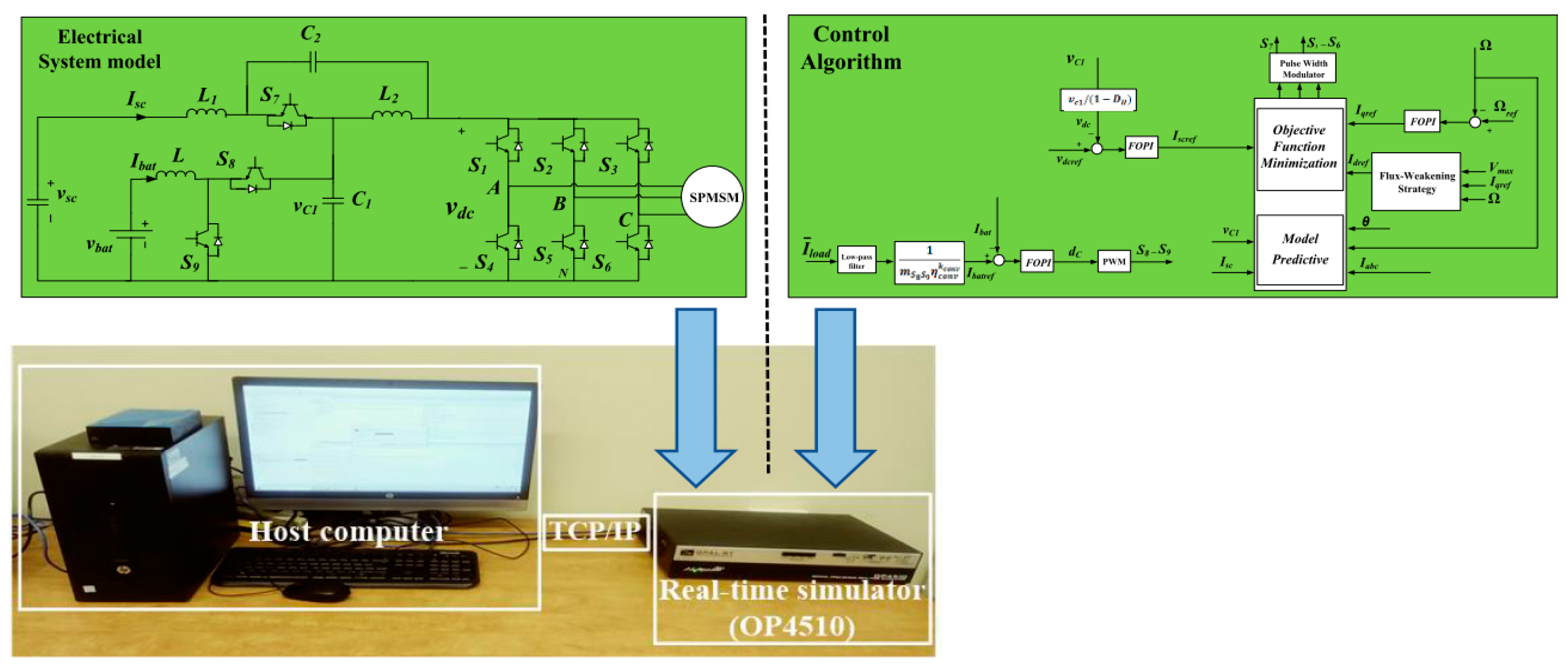
2. Hybrid Energy Storage System Configuration and Modeling

Figure 1 shows the configuration of the proposed HESS Bq-ZSI. This configuration is based on the ZSN of the Bq-ZSI composed of capacitors ( C 1 ,   C 2 ) and inductors ( L 1 , L 2 ) and the bidirectional DC-DC converter. This DC-DC converter is composed of C 1 , which represents its output capacitor, the inductor L , and the switches ( S 8 , S 9 ) . Since the shoot-through state of the Bq-ZSI could solely be altered in a zero state, its practical boost factor is commonly restricted. This may limit its applications in the EV, where the high-voltage gain is required for the ESS. To tackle this issue, the higher voltage of the battery is necessary for the Bq-ZSI; however, it might increase the EV cost, the system size, and the volume. Thus, in this study, the battery is connected to the bidirectional DC-DC converter to supply the required power for the electric motor, while the supercapacitor coupled to the qZSI network is used as backup energy storage to provide/absorb transient power during acceleration/braking operations. Moreover, the battery-absorbed and -released power are controlled in bidirectional power flows by the DC-DC converter through its switches S 7 and S 8 .
The Bq-ZSI operating principles have been largely examined in [31]. The relationship between the capacitor voltages and the supercapacitor terminal voltages during the steady state can be deduced with the shoot-through duty cycle D H by:
{ v c 1 = 1 D H 1 2 D H v s c v c 2 = D H 1 2 D H v s c    
The DC-link peak voltage v ^ d c can be derived from the sum of two capacitor voltages, v c 1 and v c 2 , by:
v ^ d c = v c 1 + v c 2 = 1 1 2 D H v s c = B v s c  
where B ≥ 1 is the boost factor resulting from the shoot-through period. Regarding the AC side of the Bq-ZSI, the peak phase voltage can be written as follows:
v ^ o = m H v ^ d c 2 = m H 1 2 D H . v s c 2 = G H v s c 2    
in which m H and G H denote the inverter modulation index and the total voltage gain of the Bq-ZSI, respectively.
The battery power exchange is controlled by the DC-DC converter, which can operate in two states, as shown in [31]. The relationship between the capacitor C 1 and the battery voltage can be expressed as:
v c 1 = 1 1 d C v b a t
where d C is the duty cycle of the DC-DC converter.
In general, the proposed HESS operation modes can be categorized into low-power, high-power [32,33], and supercapacitor energy recovery modes. In traction or regenerative operation, each of these power modes can be used. In the low-power traction/regenerative mode, the battery pack only offers the total motor power demand. In this case, there is no power exchange for the supercapacitor with the battery and the motor. Additionally, the EV traction motor receives/stores energy in the battery through modes 1 and 2, as shown in Table 1.
In the high-power traction/regenerative mode, the supercapacitor power can be discharged or charged. Its power is used to assist the battery pack to afford the motor power demand. During acceleration, the supercapacitor helps the battery to sustain the maximum traction power via mode 3 (Table 1). This enhances the response time of the EV for a request of acceleration. The major part of the regenerative power is stored in the supercapacitor during braking or deceleration through mode 8 (Table 1). This will help to extend the lifetime of the battery due to operation within a safe operating point.
The supercapacitor is charged in the supercapacitor energy recovery mode after releasing the power to maintain the energy storage level via mode 4 or 7 (Table 1).
The complete modes of HESS operation are listed in Table 1, where positive and negative denote releasing and absorbing the energy, respectively. Null indicates that the supercapacitor is bypassed. Figure 2 presents the power flow between the motor and the energy storage device in the HESS high-power traction/regenerative mode.

3. Finite Control Set Model Predictive Controller

In this study, a surface permanent magnet synchronous machine (SPMSM) is used as a traction electric motor. Its state space representation can be described as presented in [31]. The FCS-MPC and FOPI controllers are designed to improve the dynamic performance for the speed control and disturbance rejection. The FCS-MPC is an optimal control technique which provides the easy handling of constraints and fast dynamic performance [34]. In this respect, the cost function of the FCS-MPC is used for the enhanced performance, considering some parameters of the system. The FCS-MPC control technique is adopted based on the model of SPMSM. From the SPMSM side, the feedback signals are the rotor speed and the three-phase stator currents i a b c . The i d and i q currents are obtained from the measured and converted three-phase stator currents of the SPMSM. The FOPI controller is designed to achieve the speed control. It also allows for the determination of the reference current i q r e f . With the idea of ensuring correct operation with the maximum available torque within current and voltage limits at any speed, the flux weakening (FW) strategy is applied. This strategy is realized by taking into consideration the motor’s maximum allowable phase voltage and phase current. The available maximum phase voltage and maximum phase current constraints can be deduced as follows:
i d 2 + i q 2 i m a x 2  
v d 2 + v q 2 v m a x 2
where v m a x and i m a x denote the voltage and current limitations, respectively. In the constant torque region, where the motor speed is smaller than the base speed ( Ω Ω b a s e ), the i d r e f is set as zero. When the motor speed is greater than the base speed (   Ω > Ω b a s e ), the FW strategy allows for the obtention of the negative current reference i d r e f in the FW region. The i d r e f is determined from the following expression [35].
I d = ψ f L d ( Ω b a s e Ω 1 )    
where L d is the phase d inductance of the SPMSM, ψ f represents the equivalent magnetic flux linkage of the SPMSM, and Ω and Ω b a s e are the motor speed and the base speed, respectively.
According to the discrete time model obtained with the backward Euler method, as shown in [36], the state variables i s c ( k + 1 ) , v c 1 ( k + 1 ) , v c 2 ( k + 1 ) , i d ( k + 1 ) and i q ( k + 1 ) are predicted for the (k + 1)th time instant. They are also used to evaluate the predetermined cost function. The cost functions are established with the aim of minimizing the tracking error between the measured currents and the reference currents. The cost function g 1 for the SPMSM control system can be given as:
g 1 = ( i d r e f ( k + 1 ) i d ( k + 1 ) ) 2 + ( i q r e f ( k + 1 ) i q ( k + 1 ) ) 2 + f l i m with f l i m = {   i f     | i d ( k + 1 ) |   o r   | i q ( k + 1 ) | i m a x   0   i f   | i d ( k + 1 ) |   o r   | i q ( k + 1 ) | i m a x  
From the Bq-ZSI side, the cost function g 2 can be expressed as:
g 2 = ( i s c r e f ( k + 1 ) i s c ( k + 1 ) ) 2 + λ ( v c 1 ( k + 1 ) v c 2 ( k + 1 ) ) 2
where λ is the weighting factor adjusted according to the desired performance. It is used for the DC-link capacitor voltages balancing control. f l i m is a hard constraint function which limits the current output magnitude and represents a safety future. The optimal switching state associated with the minimum values of g 1 and g 2 is selected and applied to the qZSI and the SPMSM at the beginning of the next sampling time.
The inductor currents of the DC-DC converter and DC-link voltage are controlled using the FOPI controller. The bidirectional power flow is operated by the switch S7 of the Bq-ZSI. The pulse width modulation (PWM) technique is used to control the switch S7. It has a signal that is complementary with the shoot-through signal of the inverter. Figure 3 shows the control scheme of the proposed HESS. As shown in the control scheme, the low-pass filter (LPF) allows for the filtering of the average current. The filtering strategy is used to distribute the power. This strategy is formulated based on the different frequency characteristics of energy storages [37]. The low pass filter (LPF) ensures that the battery supports a low frequency power to reduce the current stress and extend the battery lifetime [38]. The filtering strategy can be achieved by using the following expression:
I b a t r e f = 1 m S 8 S 9 η c o n v k c o n v ( 1 τ L P F s + 1 ) I l o a d
where I l o a d denotes the load current. A fraction of the load average current filtered amount represented by 1 m S 8 S 9 η c o n v k c o n v is used as the battery reference current I b a t r e f , where m S 8 S 9 , η c o n v k c o n v , and k c o n v   indicate the modulation index, the efficiency, and the coefficient which depend on the DC-DC converter power direction, respectively. τ L P F represents the time constant of the LPF and is deduced by τ L P F = 1 2 π f L P F , where f L P F   is the cut-off frequency. The average current is combined with the filter to reduce the very high frequency ripple and the noise that is caused by the switching operation. The buck and boost operation of the battery are controlled through this current that is used in the bidirectional DC-DC converter. The control of this current must achieve suitable charging and discharging currents of the battery with better stability in response to the transient power variation.

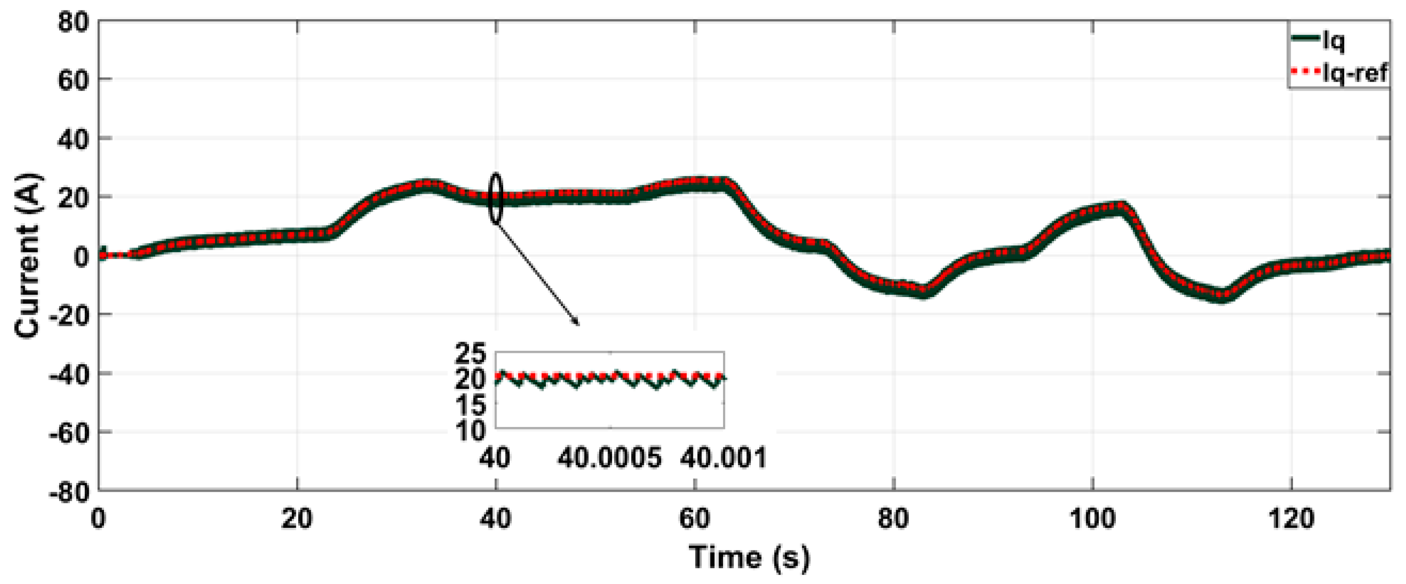
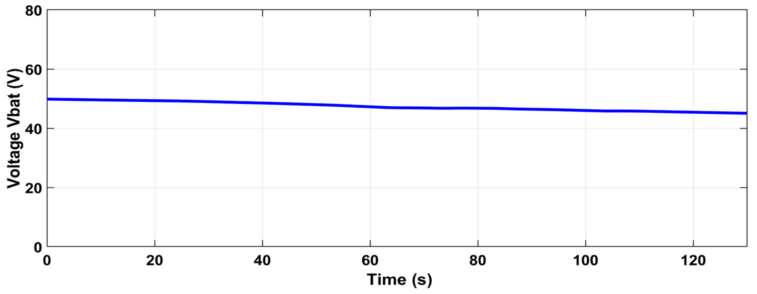
4. Results and Discussion

4.1. Real-Time Simulation Results

The OP4510-based real-time simulation from Opal-RT is performed to verify the real-time operation of the proposed control method for the SC/BAT HESS Bq-ZSI under the Artemis driving cycles with the main parameters in Table 2. In this respect, the reference EV used in this study is the e-TESC 4W platform, as presented in Figure 4. It is an off-road EV supplied by a battery pack of lithium-ion LG Chem ICR2 cells and a supercapacitor bank of Maxwell BMOD0058 E016 B02. Figure 5 shows the real-time simulation setup. The proposed HESS Bq-ZSI is first implemented on the OP4510 FPGA-based Electric Hardware Solver, and the control algorithm in Figure 3 is then executed on the OP4510 CPU, in which the controller parameters of the FOPI are presented in Table 3.
The real-time simulation results of the speed and torque waveforms are shown in Figure 6 and Figure 7, respectively. The currents i q and i d , with their references, are represented in Figure 8 and Figure 9, respectively, while the v d c voltage and its reference are shown in Figure 10. Figure 11 and Figure 12 represent the battery and supercapacitor currents and their references, respectively. The battery and supercapacitor voltages are represented in Figure 13 and Figure 14, respectively.
In Figure 6 and Figure 10, the proposed HESS Bq-ZSI shows the quick responses to the mechanical load and provides a constant DC-link voltage over the power-demand profile. The battery, the supercapacitor, and the total power of the proposed HESS during EV motor traction in the high-power mode are presented in Figure 15.
For time t < 75 s, the EV motor operates in the traction mode, while the proposed HESS conducts in the high-power mode. Both the battery pack and the supercapacitor are discharged. In this condition, the supercapacitor transfers its power to help the battery afford the motor power demand. During acceleration, the supercapacitor helps the battery offer the maximum traction power and enables the enhancement of the response time of the EV for a request of acceleration. From 75 s to 85 s, the EV motor works in the regenerative mode, and the supercapacitor implements in the recovery mode. The major part of the regenerative power is stored in the supercapacitor during the deceleration. The EV motor also operates in the traction mode, while the proposed HESS works in the high-power mode for time 85 s to 105 s. The supercapacitor affords its power to assist the battery for the required motor power. From 105 s to 130 s, the EV motor also performs in the regenerative mode, whereas the supercapacitor operates in the recovery mode. From the abovementioned results obtained, it can be inferred that integrating the supercapacitor can help the battery to provide the maximum traction power demand of the EV. Therefore, it contributes to the efficient use of battery energy to obtain a longer distance coverage.

4.2. Battery Aging Index Comparison

The aging performance indexes of the battery are determined to compare the proposed HESS Bq-ZSI using the new control configuration and powertrain original configuration (inverter directly supplied by the battery). The battery lifetime is strongly influenced by their usage mode, in which the sudden changes in large and frequent currents may result in decreasing its lifetime. The value of the root-mean-square (RMS), the mean value (μ), the standard deviation (σ) of the cell current, and the coefficient ( c ν ) characterizing the instantaneous current peaks over the driving cycle illustrate the aging performance indexes of the battery [39].
The RMS value of the cell current indicates the effective current. It can be expressed as:
RMS = 1 N i = 1 N ( I B , c e l l ( i ) ) 2        
The mean value of the cell current specifies the long-term stress from losses and the respective thermal effect on batteries. It can be written as:
μ = 1 N i = 1 N I B , c e l l ( i )  
The standard deviation defines the strong variation of the C-rate of the batteries and can be deduced by the following expression:
σ = 1 N i = 1 N ( I B , c e l l ( i ) μ ) 2  
The variation coefficient illustrating the instantaneous current peak can be determined as follows:
c ν = σ μ  
Figure 16 presents the performance comparison utilizing the aging index of the battery branches for these two topologies under the same driving cycle. As is observed, the multi-source Bq-ZSI using the proposed control configuration provides better aging indexes in terms of the RMS and the average values of the battery current. It helps to reduce the RMS, μ, and σ values by 57%, 59%, and 27%, respectively, as compared to the original ones. Moreover, using the FCS-MPC for the multi-source Bq-ZSI leads to improved aging indexes compared to only using the FOPI controllers. Based on these results, it could be concluded that using the FCS-MPC-based multi-source Bq-ZSI for the e-TESC 4W EV leads to an improvement in the battery lifetime over the original inverter and the FOPI-based multi-source Bq-ZSI, which makes it more suitable in EV systems than the original configuration.

5. Conclusions

This paper has proposed a new control configuration for multi-source Bq-ZSI based on the SC/BAT HESS for the EV. To overcome the problems of the battery rush discharging/charging currents, the bidirectional DC-DC converter is employed to connect the battery, while the ZSN of the Bq-ZSI is used to couple the supercapacitor. The proposed HESS Bq-ZSI control scheme using the FCS-MPC and the FOPI was first investigated to achieve the dynamic response that is required for energy storage devices. The real-time simulation based on Opal-RT was then implemented to validate the effectiveness of the proposed HESS control strategy. The results have proved that the proposed HESS can be well operated for different modes of the EV motor, in which independent power routines for the supercapacitor and the battery can be accomplished by the multi-source Bq-ZSI. The proposed HESS Bq-ZSI control using the FCS-MPC has shown good dynamic responses and stable DC-link voltages under the studied driving cycle. In comparison with the original configuration, the battery lifetime can be improved by using the proposed HESS Bq-ZSI with the new control structure. Moreover, the multi-source Bq-ZSI using the FCS-MPC also provided improved aging performance index values for the battery of the studied EV compared to only using the FOPI controllers.
These results indicate that the proposed HESS Bq-ZSI using the FCS-MPC improves the EV system performance. The integration of the supercapacitor into the proposed HESS allows for the efficient use of battery energy, enabling longer distance coverage and thus extending the driving range of the EV. Future work will consist of proposing a power distribution strategy in multi-source off-road EVs with a signal-hardware-in-the-loop experimental test, including a stability analysis.

Author Contributions

Conceptualization, D.M. and J.P.F.T.; Data curation, D.M., T.V.D. and J.P.F.T.; Funding acquisition, J.P.F.T.; Methodology, J.P.F.T. and M.C.T.; Project administration, J.P.F.T.; Validation, J.P.F.T. and M.C.T.; Writing—original draft, D.M.; Writing—review & editing, J.P.F.T. and M.C.T. All authors have read and agreed to the published version of the manuscript.

Funding

This work was supported in part by Grant 950-230672 from the Canada Research Chairs Program, in part by Grant RGPIN-2017-05924 from the Natural Sciences and Engineering Research Council of Canada, and in part by the FCT-Portuguese Foundation for Science and Technology project UIDB/00308/2020.

Institutional Review Board Statement

Not applicable.

Informed Consent Statement

Not applicable.

Conflicts of Interest

The authors declare no conflict of interest.

References

  1. Chemali, E.; Preindl, M.; Malysz, P.; Emadi, A. Electrochemical and electrostatic energy storage and management systems for electric drive vehicles: State-of-the-Art review and future trends. IEEE J. Emerg. Sel. Top. Power Electron. 2016, 4, 1117–1134. [Google Scholar] [CrossRef]
  2. Zimmermann, T.; Keil, P.; Hofmann, M.; Horsche, M.F.; Pichlmaier, S.; Jossen, A. Review of system topologies for hybrid electrical energy storage systems. J. Energy Storage 2016, 8, 78–90. [Google Scholar] [CrossRef]
  3. Hemmati, R.; Saboori, H. Emergence of hybrid energy storage systems in renewable energy and transport applications—A review. Renew. Sustain. Energy Rev. 2016, 65, 11–23. [Google Scholar] [CrossRef]
  4. Jiya, I.N.; Gurusinghe, N.; Gouws, R. Combination of LiCs and EDLCs with Batteries: A New Paradigm of Hybrid Energy Storage for Application in EVs. World Electr. Veh. J. 2018, 9, 47. [Google Scholar] [CrossRef]
  5. Chia, Y.Y.; Lee, L.H.; Shafiabady, N.; Isa, D. A load predictive energy management system for supercapacitor-battery hybrid energy storage system in solar application using the Support Vector Machine. Appl. Energy 2015, 137, 588–602. [Google Scholar] [CrossRef]
  6. Monem, M.A.; Trad, K.; Omar, N.; Hegazy, O.; Mantels, B.; Mulder, G.; van den Bossche, P.; van Mierlo, J. Lithium-ion batteries: Evaluation study of different charging methodologies based on aging process. Appl. Energy 2015, 152, 143–155. [Google Scholar] [CrossRef]
  7. Sarasketa-Zabala, E.; Gandiaga, I.; Martinez-Laserna, E.; Rodriguez-Martinez, L.M.; Villarreal, I. Cycle ageing analysis of a LiFePO 4 /graphite cell with dynamic model validations: Towards realistic lifetime predictions. J. Power Sources 2015, 275, 573–587. [Google Scholar] [CrossRef]
  8. Preger, Y.; Barkholtz, H.M.; Fresquez, A.; Campbell, D.L.; Juba, B.W.; Romàn-Kustas, J.; Ferreira, S.R.; Chalamala, B. Degradation of Commercial Lithium-Ion Cells as a Function of Chemistry and Cycling Conditions. J. Electrochem. Soc. 2020, 167, 120532. [Google Scholar] [CrossRef]
  9. Gomozov, O.; Trovão, J.P.F.; Kestelyn, X.; Dubois, M.R. Adaptive Energy Management System Based on a Real-Time Model Predictive Control with Nonuniform Sampling Time for Multiple Energy Storage Electric Vehicle. IEEE Trans. Veh. Technol. 2016, 66, 5520–5530. [Google Scholar] [CrossRef]
  10. Kuperman, A.; Aharon, I.; Malki, S.; Kara, A. Design of a Semiactive Battery-Ultracapacitor Hybrid Energy Source. IEEE Trans. Power Electron. 2012, 28, 806–815. [Google Scholar] [CrossRef]
  11. Chemali, E.; McCurlie, L.; Howey, B.; Stiene, T.; Rahman, M.M.; Preindl, M.; Ahmed, R.; Emadi, A. Minimizing battery wear in a hybrid energy storage system using a linear quadratic regulator. In Proceedings of the IECON 2015—41st Annual Conference of the IEEE Industrial Electronics Society, Yokohama, Japan, 9–12 November 2015. [Google Scholar]
  12. Siwakoti; Peng, F.; Blaabjerg, F. Impedance-source networks for electric power conversion part I: A topological review. IEEE Trans. Power Electron. 2015, 30, 699–716. [Google Scholar] [CrossRef]
  13. Ellabban, O.; Abu-Rub, H. Z-source inverter: Topology improvements review. IEEE Ind. Electron. Mag. 2016, 10, 6–24. [Google Scholar] [CrossRef]
  14. Liu, Y.; Ge, B.; Ferreira, F.J.T.E.; de Almeida, A.T.; Rub, A.A. Modelling and SVPWM control of quasi-Z-source inverter. In Proceedings of the 11th International Conference on Electrical Power Quality and Utilisation, Lisbon, Portugal, 17–19 October 2011. [Google Scholar]
  15. Jung, J.; Keyhani, A. Control of a Fuel Cell Based Z-Source Converter. IEEE Trans. Energy Convers. 2007, 22, 467–476. [Google Scholar] [CrossRef]
  16. Shen, M.; Joseph, A.; Wang, J.; Peng, F.Z.; Adams, D.J. Comparison of traditional inverters and Z-source inverter for fuel cell vehicles. IEEE Trans. Power Electron. 2007, 22, 1453–1463. [Google Scholar] [CrossRef]
  17. Hu, S.; Liang, Z.; He, X. Ultracapacitor-Battery Hybrid Energy Storage System Based on the Asymmetric Bidirectional Z-Source Topology for EV. IEEE Trans. Power Electron. 2015, 31, 7489–7498. [Google Scholar] [CrossRef]
  18. Aljanad, A.; Mohamed, A.; Khatib, T.; Ayob, A.; Shareef, H. A Novel Charging and Discharging Algorithm of Plug-in Hybrid Electric Vehicles Considering Vehicle-to-Grid and Photovoltaic Generation. World Electr. Veh. J. 2019, 10, 61. [Google Scholar] [CrossRef]
  19. Wang, G.; Ciobotaru, M.; Agelidis, V.G. Power Smoothing of Large Solar PV Plant Using Hybrid Energy Storage. IEEE Trans. Sustain. Energy 2014, 5, 834–842. [Google Scholar] [CrossRef]
  20. Chong, L.W.; Wong, Y.W.; Rajkumar, R.K.; Rajkumar, R.K.; Isa, D. Hybrid energy storage systems and control strategies for stand-alone renewable energy power systems. Renew. Sustain. Energy Rev. 2016, 66, 174–189. [Google Scholar] [CrossRef]
  21. Yu, J.; Jiang, F.; Kong, W.; Luo, Y. A Distributed and Hierarchical Optimal Control Method for Intelligent Connected Vehicles in Multi-Intersection Road Networks. World Electr. Veh. J. 2022, 13, 34. [Google Scholar] [CrossRef]
  22. Ort´uzar, M.; Moreno, J.; Dixon, J. Ultracapacitor-based auxiliary energy system for an electric vehicle: Implementation and evaluation. IEEE Trans. Ind. Electron. 2007, 54, 2147–2156. [Google Scholar] [CrossRef]
  23. Wang, P.; Xiao, J.; Setyawan, L. Hierarchical Control of Hybrid Energy Storage System in DC Microgrids. IEEE Trans. Ind. Electron. 2015, 62, 4915–4924. [Google Scholar] [CrossRef]
  24. Nosrati, K.; Mansouri, H.R.; Saboori, H. Fractional-order PID controller design of frequency deviation in a hybrid renewable energy generation and storage system. CIRED-Open Access Proc. J. 2017, 2017, 1148–1152. [Google Scholar] [CrossRef]
  25. Yaramasu, V.; Wu, B.; Rivera, M.; Rodriguez, J. Enhanced model predictive voltage control of four-leg inverters with switching frequency reduction for standalone power systems. In Proceedings of the 2012 15th International Power Electronics and Motion Control Conference (EPE/PEMC), Novi Sad, Serbia, 4–6 September 2012. [Google Scholar]
  26. Choi, D.K.; Lee, K.B. Dynamic Performance Improvement of AC/DC Converter Using Model Predictive Direct Power Control With Finite Control Set. IEEE Trans. Ind. Electron. 2014, 62, 757–767. [Google Scholar] [CrossRef]
  27. Murali, A.; Wahab, R.S.; Gade, C.S.R.; Annamalai, C.; Subramaniam, U. Assessing Finite Control Set Model Predictive Speed Controlled PMSM Performance for Deployment in Electric Vehicles. World Electr. Veh. J. 2021, 12, 41. [Google Scholar] [CrossRef]
  28. Mendez, R.; Sbarbaro, D.; Espinoza, J.; Rojas, C. Finite Control Set Model Predictive Control Assisted by a Linear Controller for True Parameter Uncertainty Compensation. In Proceedings of the 2017 IEEE Energy Conversion Congress and Exposition (ECCE), Cincinnati, OH, USA, 1–5 October 2017; pp. 4964–4970. [Google Scholar]
  29. Bakeer, A.; Ismeil, M.A.; Orabi, M. A powerful finite control set-model predictive control algorithm for quasi z-source inverter. IEEE Trans. Ind. Inform. 2016, 12, 1371–1379. [Google Scholar] [CrossRef]
  30. Mande, D.; Blondin, M.; Trovão, J.P.F. Optimisation of fractional-order PI controller for bidirectional quasi-Z-source inverter used for electric traction system. IET Electr. Syst. Transp. 2020, 10, 376–384. [Google Scholar] [CrossRef]
  31. Mande, D.; Trovão, J.P.; Rubio, R.G.; Ta, M.C. Comparison of Bidirectional Quasi Z-Source Inverter and Bidirectional Conventional Two-Stage Inverter for Electric Traction System. In Proceedings of the 2018 IEEE Vehicle Power and Propulsion Conference (VPPC), Chicago, IL, USA, 27–30 August 2018. [Google Scholar]
  32. Dehghan, S.M.; Mohamadian, M.; Yazdian, A. Hybrid electric vehicle based on bidirectional Z-source nine-switch inverter. IEEE Trans. Veh. Technol. 2010, 59, 2641–2653. [Google Scholar] [CrossRef]
  33. Peng, F.Z.; Shen, M.; Holland, K. Application of Z-source inverter for traction drive of fuel cell—Battery hybrid electric vehicles. IEEE Trans. Power Electron. 2007, 22, 1054–1061. [Google Scholar] [CrossRef]
  34. Cortes, P.; Ortiz, G.; Yuz, J.I.; Rodriguez, J.; Vazquez, S.; Franquelo, L.G. Model predictive control of an inverter with output LC filter for UPS applications. IEEE Trans. Power Electron. 2009, 56, 1875–1883. [Google Scholar] [CrossRef]
  35. Sepulchre, L.; Fadel, M.; Pietrzak-David, M.; Porte, G. Flux-weakening strategy for high speed PMSM for vehicle application. In Proceedings of the 2016 International Conference on Electrical Systems for Aircraft, Railway, Ship Propulsion and Road Vehicles & International Transportation Electrification Conference (ESARS-ITEC), Toulouse, France, 2–4 November 2016. [Google Scholar]
  36. Liu, Y.; Abu-Rub, H.; Xue, Y.; Tao, F. A Discrete-Time Average Model-Based Predictive Control for a Quasi-Z-Source Inverter. IEEE Trans. Ind. Electron. 2018, 65, 6044–6054. [Google Scholar] [CrossRef]
  37. Thounthong, P.; Rael, S. The benefits of hybridization. IEEE Ind. Electron. Mag. 2009, 3, 25–37. [Google Scholar] [CrossRef]
  38. Song, Z.; Hofmann, H.; Li, J.; Hou, J.; Han, X.; Ouyang, M. Energy management strategies comparison for electric vehicles with hybrid energy storage system. Appl. Energy 2014, 134, 321–331. [Google Scholar] [CrossRef]
  39. Goussian, A.; LeBel, F.-A.; Trovão, J.P.; Boulon, L. Passive hybrid energy storage system based on lithium-ion capacitor for an electric motorcycle. J. Energy Storage 2019, 25, 100884. [Google Scholar] [CrossRef]
Figure 1. Proposed HESS Bq-ZSI configuration.
Wevj 13 00174 g001
Figure 2. Power flow direction during the high-power mode operation: (a) traction mode (b) regenerative mode.
Wevj 13 00174 g002
Figure 3. The control scheme for multi-source Bq-ZSI.
Wevj 13 00174 g003
Figure 4. e-TESC 4W platform (adapted from BRP e-Commander vehicle).
Wevj 13 00174 g004
Figure 5. Real-time simulation setup.
Wevj 13 00174 g005
Figure 6. Motor speed and reference.
Wevj 13 00174 g006
Figure 7. Motor torque and reference.
Wevj 13 00174 g007
Figure 8. i q current and reference.
Wevj 13 00174 g008
Figure 9. i d current and reference.
Wevj 13 00174 g009
Figure 10.   v d c voltage and reference.
Wevj 13 00174 g010
Figure 11. Battery current and reference.
Wevj 13 00174 g011
Figure 12. Supercapacitor current and reference.
Wevj 13 00174 g012
Figure 13. Battery voltage   v b a t .
Wevj 13 00174 g013
Figure 14. Supercapacitor voltage   v s c .
Wevj 13 00174 g014
Figure 15. Power of the battery and the supercapacitor.
Wevj 13 00174 g015
Figure 16. Performance comparison using aging index factors.
Wevj 13 00174 g016
Table 1. Operation modes of the HESS.
SupercapacitorBatteryMotor
Mode 1Null +
Mode 2Null +
Mode 3 + +
Mode 4 +
Mode 5 +
Mode 6 + +
Mode 7 + +
Mode 8 +
Table 2. Parameters of EV platform.
ParametersVariable NameValues
Vehicle (e-Commander)
Total mass of the EV 857   kg
Aerodynamic standard A 1.3
Rolling coefficient 0.035
Air density (at 20 °C) ρ 1.223   kg / m 3
Motor-to-wheel-transmission ratio 20.5
Efficiency of the transmission 0.87
Wheel radius 0.3175 m
Parameters of SPMSM
Phase inductance L d ,   L q 1 mH
Phase resistance r s 0.08 Ω
Number of pole pairsnp2
Global inertia referred to the rotorJ1 kg.m2
Equivalent magnetic flux linkage ψ f 0.1 Wb
Rated power P r 15 kW
Parameters of original configuration
InductanceL 2.5   μ H
CapacitanceC4.5 mF
Switching frequencyFs10 kHz
Parameters of multi-source Bq-ZSI parameters
InductanceL1, L2660 μH
InductanceL2.72 mH
CapacitanceC14.9 mF
CapacitanceC28.9 mF
Cut-off frequency of LPF f L P F 40 mHz
Switching frequencyFs10 kHz
Batteries (Lithium-ion LG Chem ICR2 cell)
Cell capacitance C b a t c e l l 2500 mAh
Cell maximum voltage v c e l l m a x 4.2 V
Number of cells in series N s 12
Number of branches in parallel N p 48
Supercapacitor (Maxwell BMOD0058 E016 B02)
Rated capacitance C s c 58 F
Nominal voltage v s c n o m 16 V
Number of series capacitors N s 4
Number of parallels capacitors N p 4
Internal resistance r s c 22   m Ω
Table 3. FOPI controller parameters summary.
Parameters K p v K i v λ v K p L K i L λ L K p C K i C λ C
FOPI StructureMotor SpeedBattery CurrentDC-Link Voltage
Value0.20863.42460.10000.107515.91370.75000.023122.96880.7000
Publisher’s Note: MDPI stays neutral with regard to jurisdictional claims in published maps and institutional affiliations.

