
High-Frequency Common-Mode Voltage Reduced Space Vector Modulation for Grid-Connected Current-Source Inverter


Abstract
:1. Introduction
2. Review of the Literature
3. CMV of a CSI
4. Proposed Five-Segment Sequence AZS-SVM for HF-CMV Mitigation
4.1. Conventional SVM
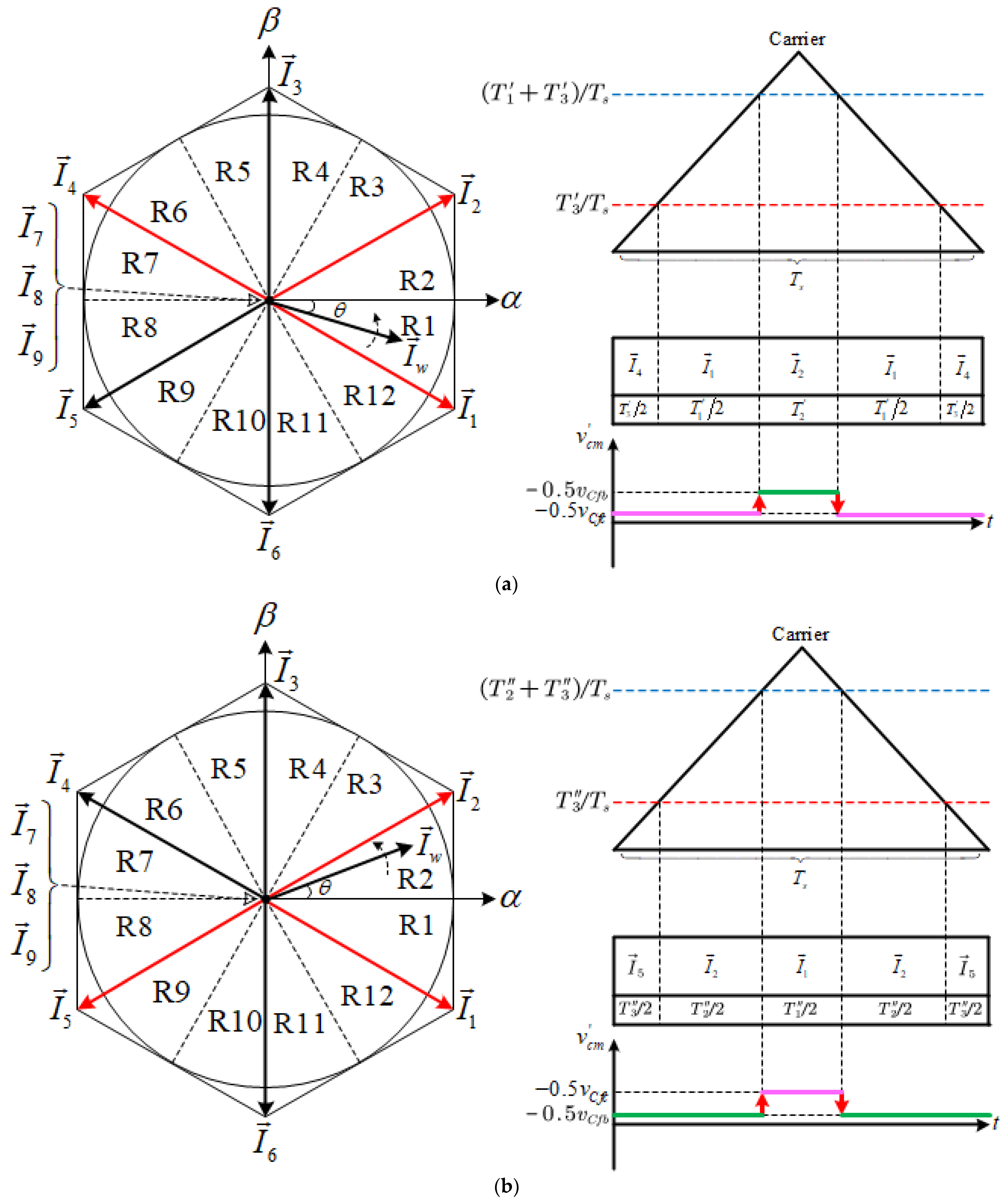
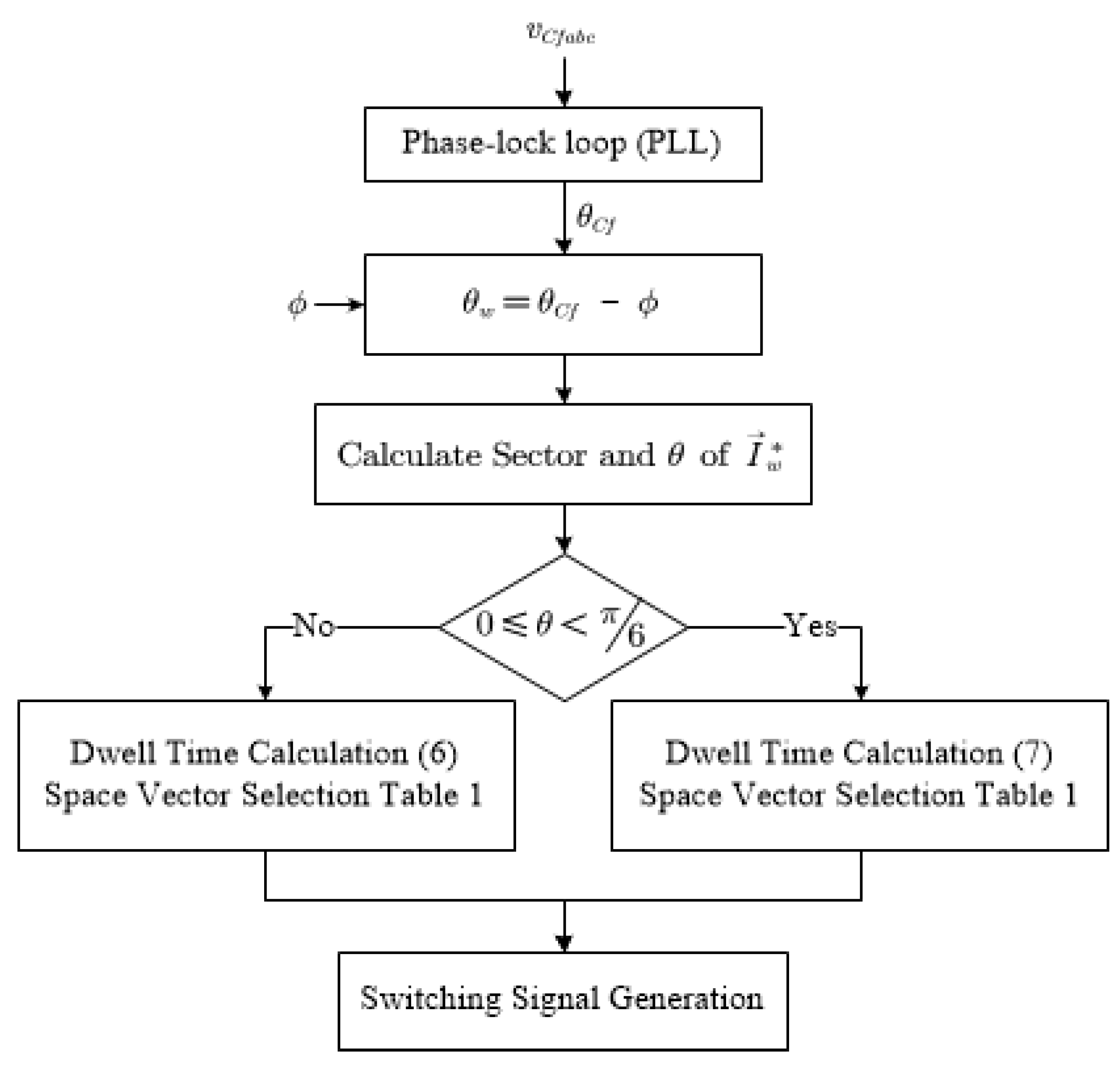
4.2. AZS-SVM
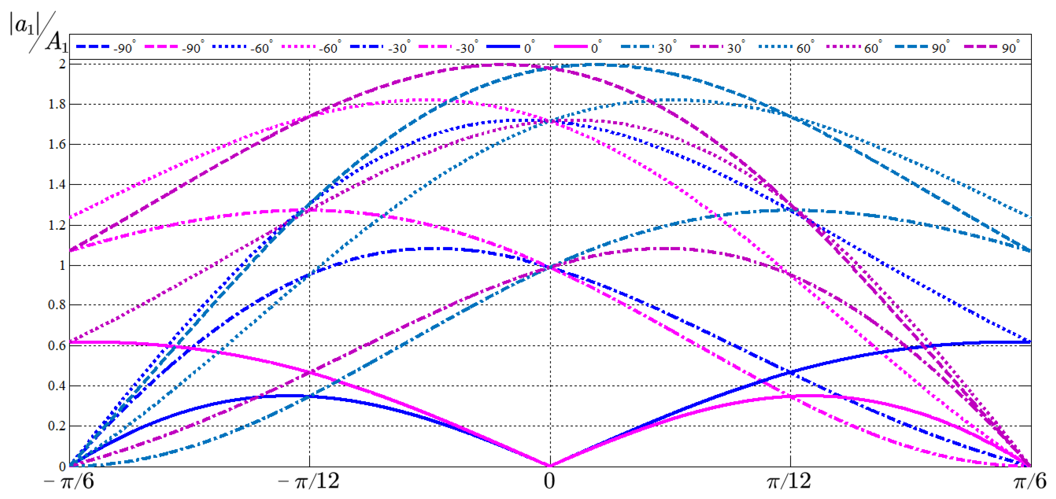
4.3. Discussion on Third Active-State Vector Selection
5. Simulation Verification
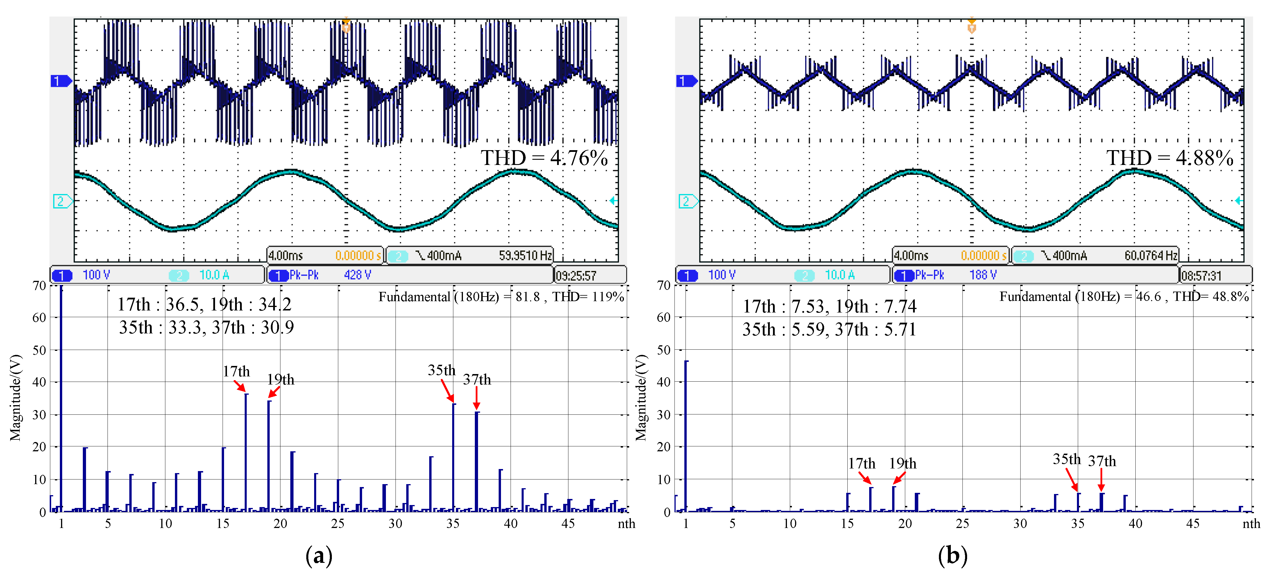
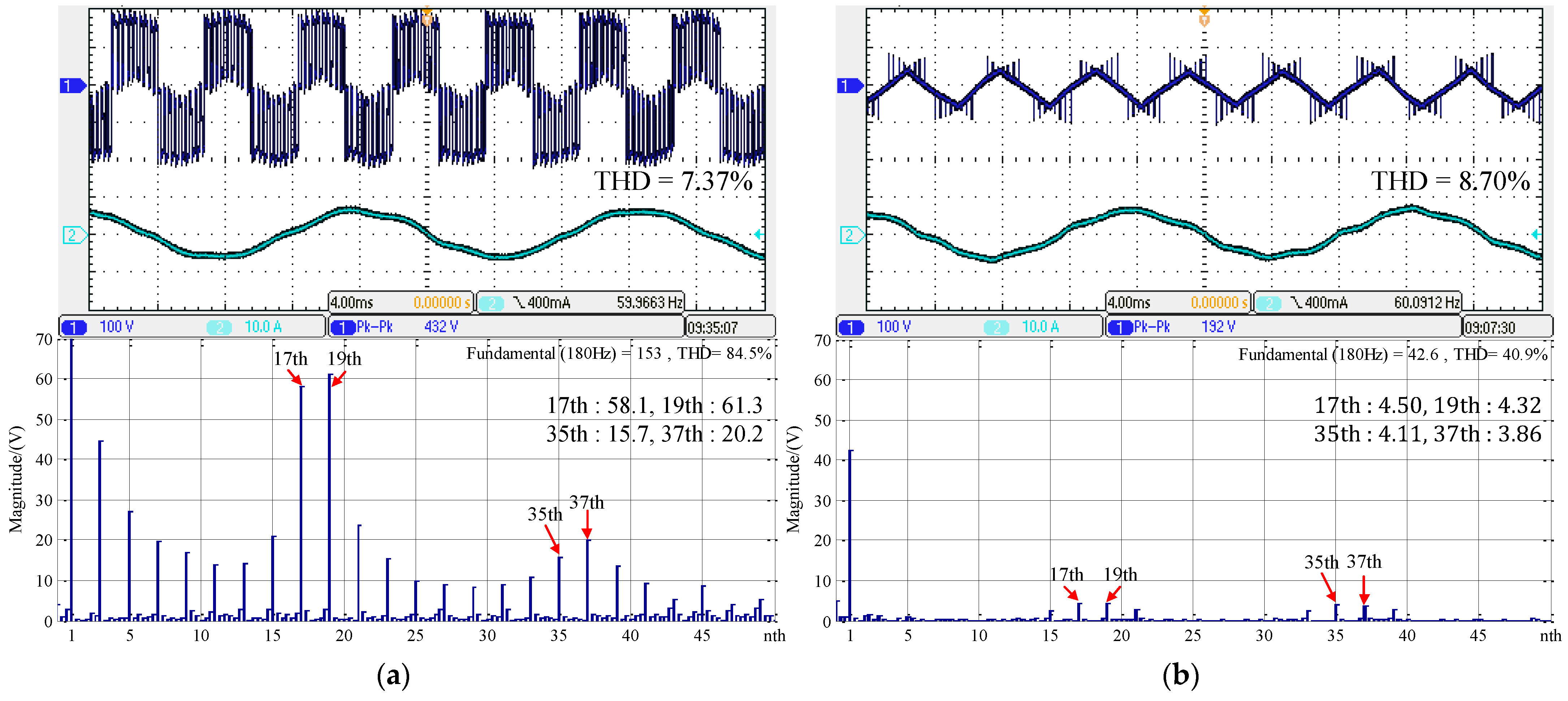
6. Experimental Verification
7. Conclusions
Author Contributions
Funding
Data Availability Statement
Conflicts of Interest
Abbreviations
| DC inductance | |
| switching signal | |
| Filter capacitor voltage | |
| Output PWM current | |
| Line current | |
| Common-mode voltage | |
| Space vector | |
| Amplitude of filter capacitor voltage | |
| Sector number | |
| Control period | |
| Control frequency | |
| Phase angle of filter capacitor voltage vector | |
| Phase angle difference | |
| Phase angle of output PWM current inside one sector |
References
- Romero-Cadaval, E.; Spagnuolo, G.; Franquelo, L.G.; Ramos-Paja, C.A.; Suntio, T.; Xiao, W.M. Grid-connected photovoltaic generation plants: Components and operation. IEEE Ind. Ind. Electron. Electron. Mag. Mag. 2013, 7, 6–20. [Google Scholar] [CrossRef] [Green Version]
- Yaramasu, V.; Wu, B.; Sen, P.C.; Kouro, S.; Narimani, M. High-power wind energy conversion systems: State-of-the-art and emerging technologies. Proc. IEEE 2015, 103, 740–788. [Google Scholar] [CrossRef]
- Iqbal, S.; Jan, M.U.; Anis Ur, R.; Rehman, A.U.; Shafiq, A.; Rehman, H.U.; Aurangzeb, M. Feasibility Study and Deployment of Solar Photovoltaic System to Enhance Energy Economics of King Abdullah Campus, University of Azad Jammu and Kashmir Muzaffarabad, AJK Pakistan. IEEE Access 2022, 10, 5440–5455. [Google Scholar] [CrossRef]
- Zhang, L.; Sun, K.; Xing, Y.; Xing, M. H6 Transformerless Full-Bridge PV Grid-Tied Inverters. IEEE Trans. Power Electron. 2014, 29, 1229–1238. [Google Scholar] [CrossRef]
- Li, W.; Gu, Y.; Luo, H.; Cui, W.; He, X.; Xia, C. Topology Review and Derivation Methodology of Single-Phase Transformerless Photovoltaic Inverters for Leakage Current Suppression. IEEE Trans. Ind. Electron. 2015, 62, 4537–4551. [Google Scholar] [CrossRef]
- Wu, F.; Sun, B.; Duan, J.; Zhao, K. Online Variable Topology-Type Photovoltaic Grid-Connected Inverter. IEEE Trans. Ind. Electron. 2015, 62, 4814–4822. [Google Scholar] [CrossRef]
- Gupta, A.; Yadav, O.P.; DeVoto, D.; Major, J. A review of degradation behavior and modeling of capacitors. In Proceedings of International Electronic Packaging Technical Conference and Exhibition; American Society of Mechanical Engineers: New York, NY, USA, 2018; p. V001T004A004. [Google Scholar]
- Wu, B.; Narimani, M. High-Power Converters and AC Drives; John Wiley & Sons: Hoboken, NJ, USA, 2017. [Google Scholar]
- Dai, J.; Lang, Y.; Wu, B.; Xu, D.; Zargari, N.R. A multisampling SVM scheme for current source converters with superior harmonic performance. IEEE Trans. Power Electron. 2009, 24, 2436–2445. [Google Scholar]
- Gao, H.; Wu, B.; Xu, D.; Pande, M.; Aguilera, R.P. Common-mode-voltage-reduced model-predictive control scheme for current-source-converter-fed induction motor drives. IEEE Trans. Power Electron. 2016, 32, 4891–4904. [Google Scholar] [CrossRef]
- Shang, J.; Li, Y.W.; Zargari, N.R.; Cheng, Z. PWM strategies for common-mode voltage reduction in current source drives. IEEE Trans. Power Electron. 2013, 29, 5431–5445. [Google Scholar] [CrossRef]
- Zhu, N.; Xu, D.; Wu, B.; Zargari, N.R.; Kazerani, M.; Liu, F. Common-mode voltage reduction methods for current-source converters in medium-voltage drives. IEEE Trans. Power Electron. 2012, 28, 995–1006. [Google Scholar] [CrossRef]
- Guo, X. A Novel CH5 Inverter for Single-Phase Transformerless Photovoltaic System Applications. IEEE Trans. Circuits Syst. II Express Briefs 2017, 64, 1197–1201. [Google Scholar] [CrossRef]
- Guo, X. Three-Phase CH7 Inverter With a New Space Vector Modulation to Reduce Leakage Current for Transformerless Photovoltaic Systems. IEEE J. Emerg. Sel. Top. Power Electron. 2017, 5, 708–712. [Google Scholar] [CrossRef]
- Guo, X.; Wang, N.; Zhang, J.; Wang, B.; Nguyen, M. A Novel Transformerless Current Source Inverter for Leakage Current Reduction. IEEE Access 2019, 7, 50681–50690. [Google Scholar] [CrossRef]


| Region | Selected Vectors | Region | Selected Vectors |
|---|---|---|---|
| 1 | , , | 7 | , , |
| 2 | , , | 8 | , , |
| 3 | , , | 9 | , , |
| 4 | , , | 10 | , , |
| 5 | , , | 11 | , , |
| 6 | , , | 12 | , , |
| Variable | Description | Value |
|---|---|---|
| VgN | Nominal line-to-line voltage | 208 V |
| PN | Nominal power | 2.5 kW |
| Lf | Filter inductance | 5 mH |
| Cf | Filter capacitance | 66 μF |
| Ldc | DC link inductance | 10 mH |
| Ts | Control period | 1/3240 s |
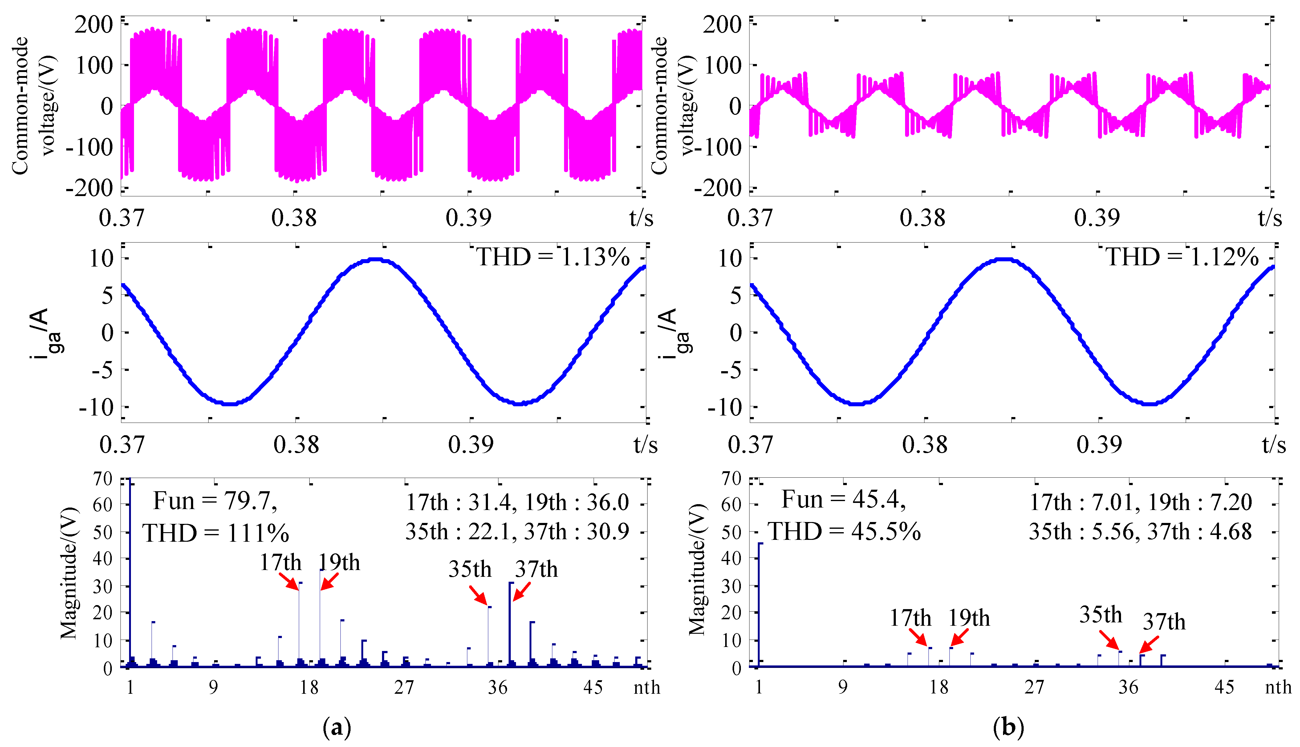
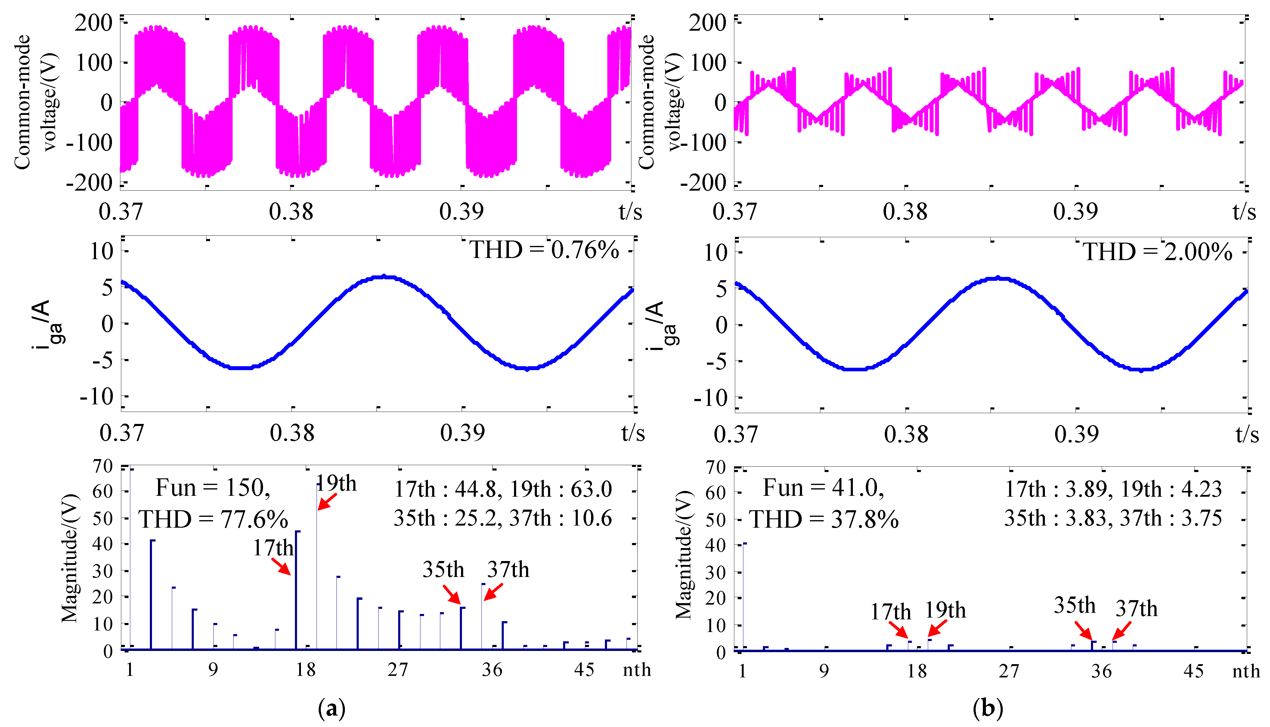
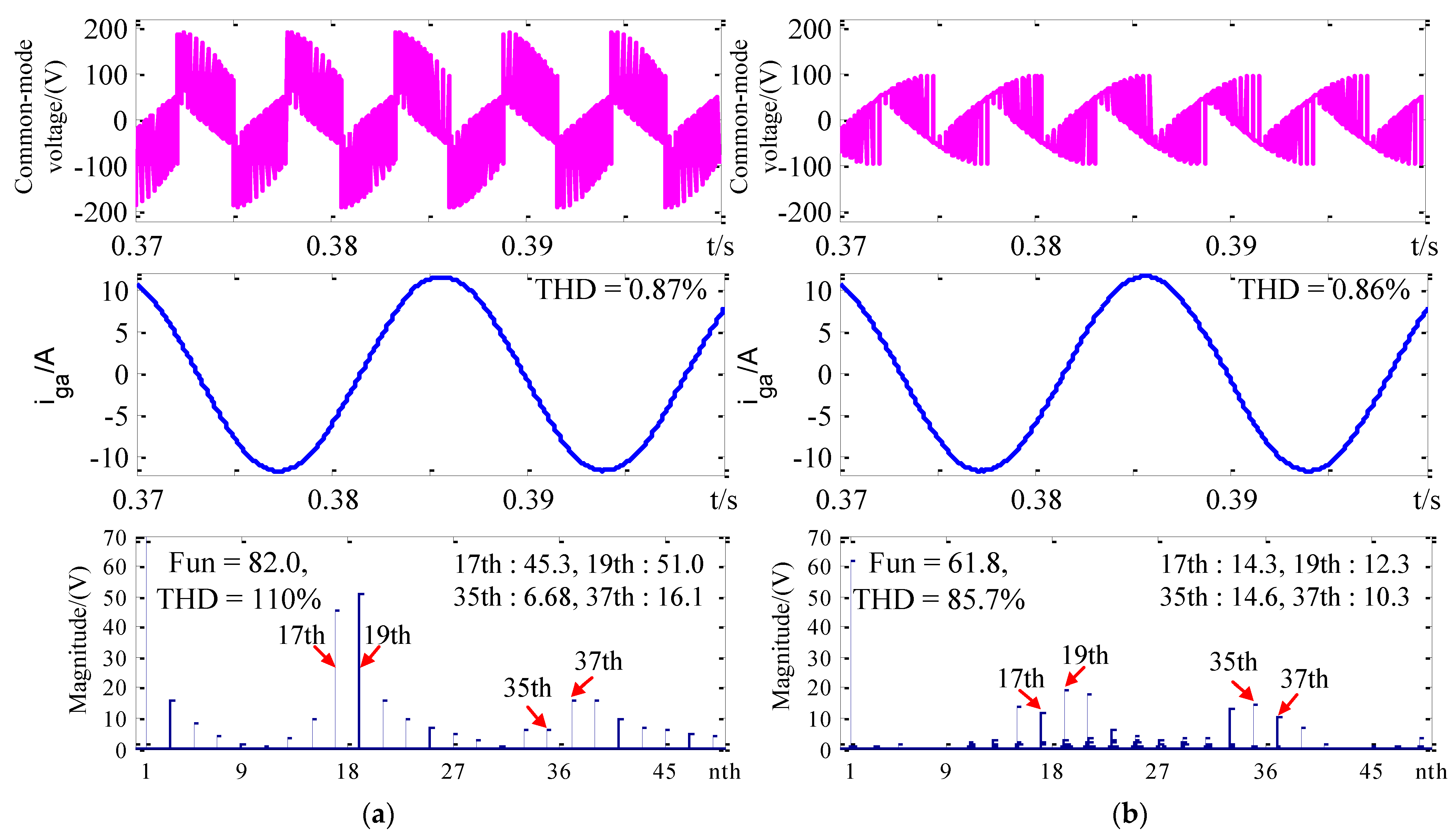
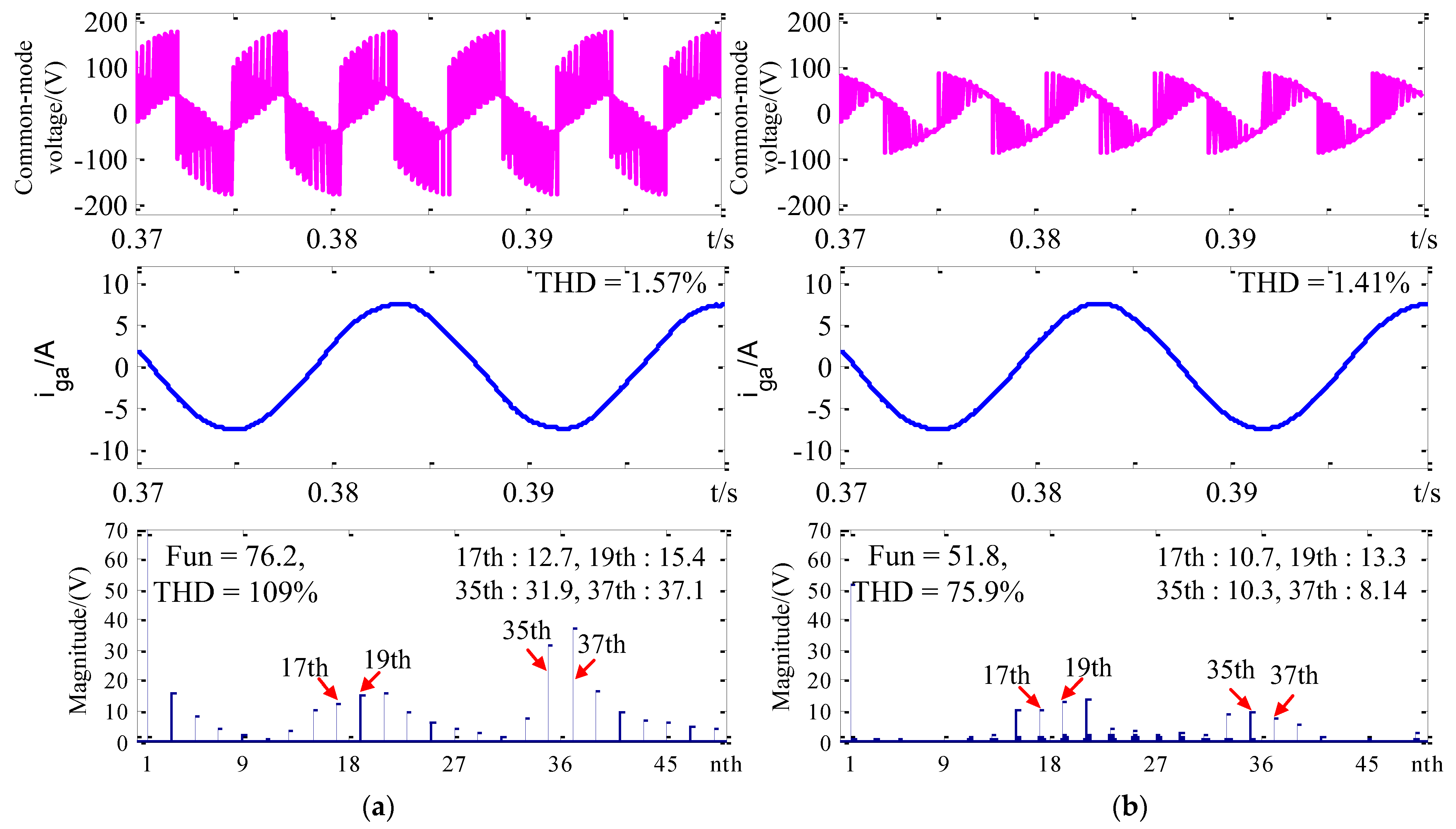
| ϕ | Modulation | HF-CMV/(V) | |||
|---|---|---|---|---|---|
| 17th | 19th | 35th | 37th | ||
| 60° | SVM1 | 56.5 | 62.2 | 20.6 | 11.7 |
| SVM2 | 27.2 | 40.1 | 28.3 | 20.2 | |
| 30° | SVM1 | 54.8 | 61.7 | 8.08 | 19.5 |
| SVM2 | 14.9 | 23.5 | 17.7 | 12.5 | |
| −30° | SVM1 | 15.4 | 18.5 | 38.6 | 44.9 |
| SVM2 | 12.9 | 16.1 | 12.5 | 9.85 | |
| −60° | SVM1 | 13.4 | 15.7 | 39.2 | 40.3 |
| SVM2 | 6.05 | 23.1 | 21.3 | 16.0 | |
Publisher’s Note: MDPI stays neutral with regard to jurisdictional claims in published maps and institutional affiliations. |
© 2022 by the authors. Licensee MDPI, Basel, Switzerland. This article is an open access article distributed under the terms and conditions of the Creative Commons Attribution (CC BY) license (https://creativecommons.org/licenses/by/4.0/).
Share and Cite
Gao, H.; Mahmud, T. High-Frequency Common-Mode Voltage Reduced Space Vector Modulation for Grid-Connected Current-Source Inverter. World Electr. Veh. J. 2022, 13, 236. https://doi.org/10.3390/wevj13120236
Gao H, Mahmud T. High-Frequency Common-Mode Voltage Reduced Space Vector Modulation for Grid-Connected Current-Source Inverter. World Electric Vehicle Journal. 2022; 13(12):236. https://doi.org/10.3390/wevj13120236
Chicago/Turabian StyleGao, Hang, and Tahmin Mahmud. 2022. "High-Frequency Common-Mode Voltage Reduced Space Vector Modulation for Grid-Connected Current-Source Inverter" World Electric Vehicle Journal 13, no. 12: 236. https://doi.org/10.3390/wevj13120236