
Electric Vehicle Air Conditioning System and Its Optimization for Extended Range—A Review


Abstract
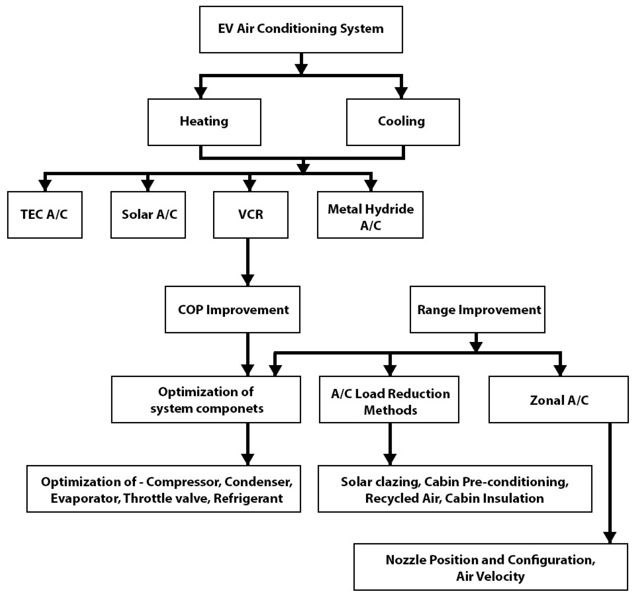
:1. Introduction
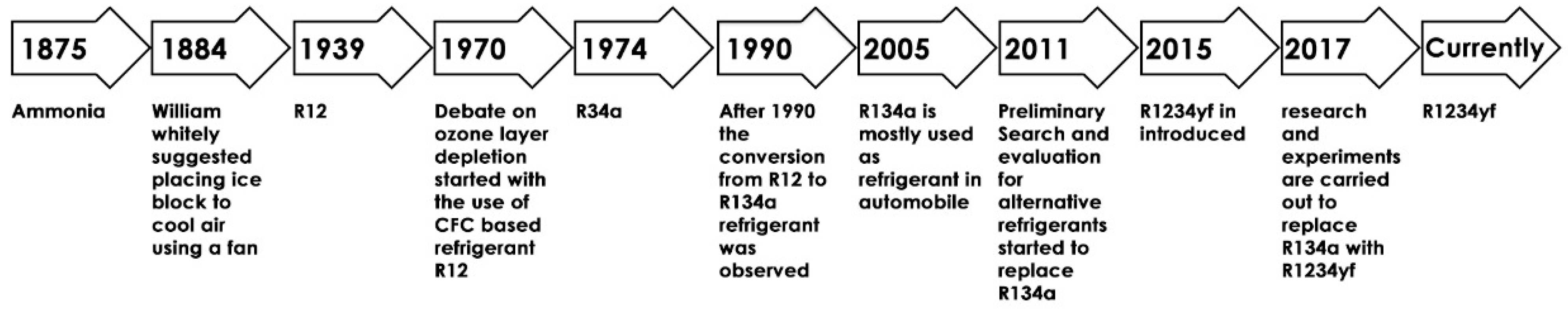
1.1. History of AC
1.2. Winter Air Conditioning (Heating)
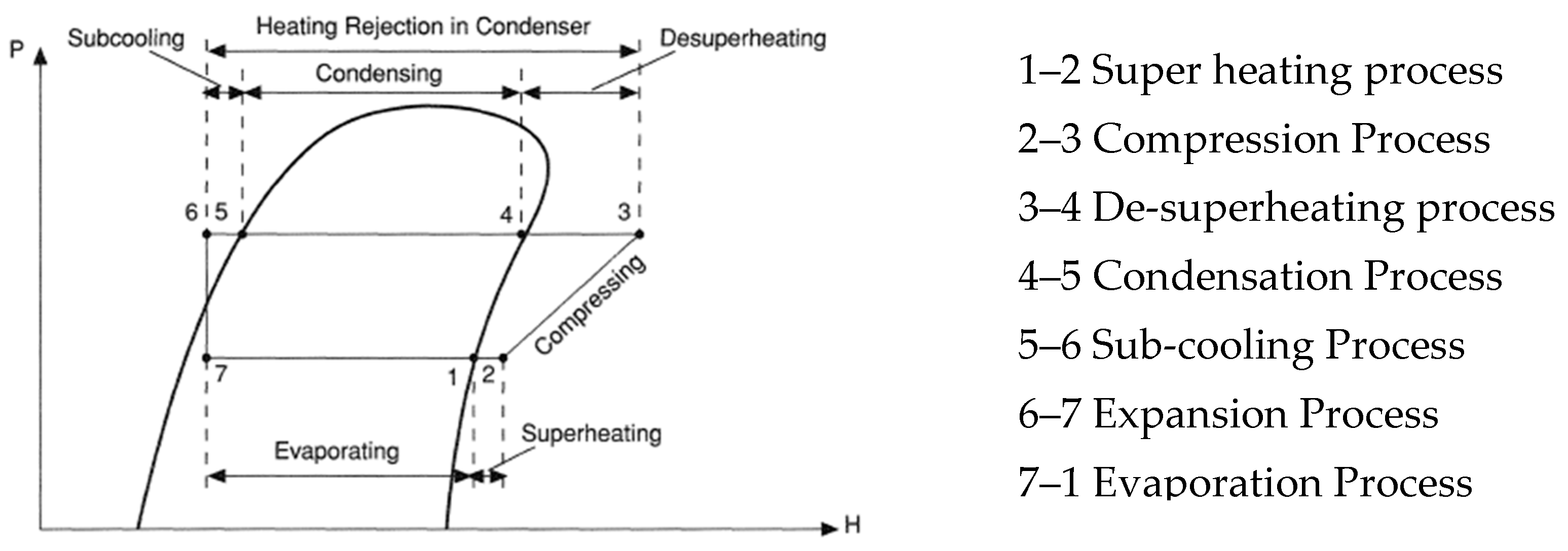
1.3. Vapor-Compression Refrigeration System
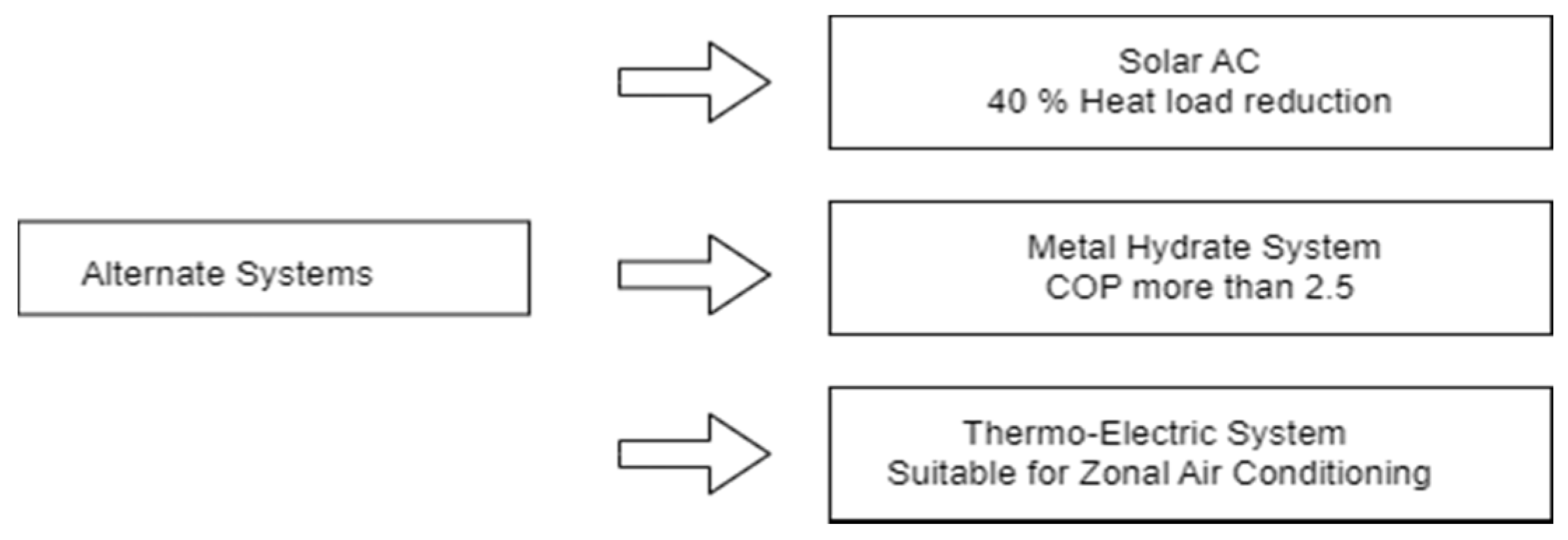
1.3.1. Solar Air Conditioning
1.3.2. Metal Hydride Air Conditioning
1.3.3. Thermoelectric System
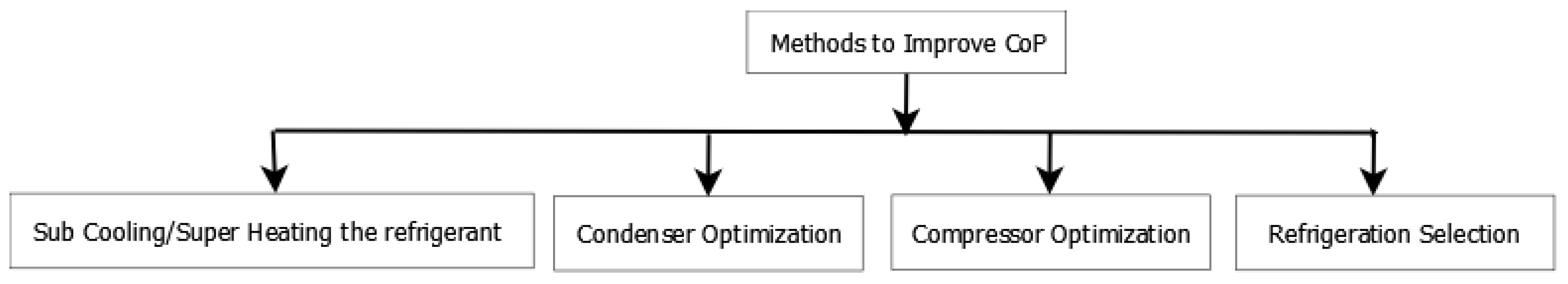
2. Ways to Improve Performance of VCR Systems
2.1. Condenser
- ○
- how to produce automated perfect control of output amount, pressure, and temperature of the refrigerant;
- ○
- how to avoid backpressure due to the accumulation of refrigerant in the condenser;
- ○
- how to produce a new separate control system for the quality of the refrigerant at the exit of the condenser; and
- ○
- how to produce a reduction in size and weight with improved performance.
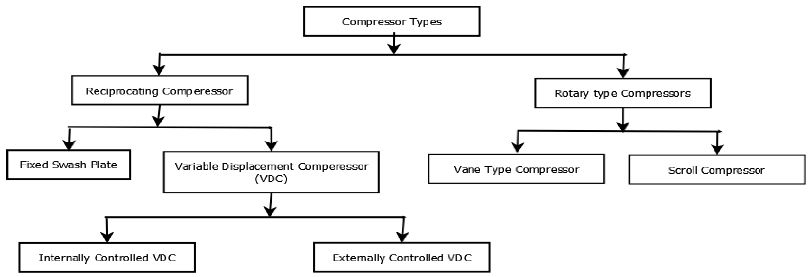
2.2. Compressor
2.3. Refrigerant
2.4. Thermal Expansion Valve
3. Air Conditioner Control Schemes
Speed of the Vehicle and Internal Temperature Distribution
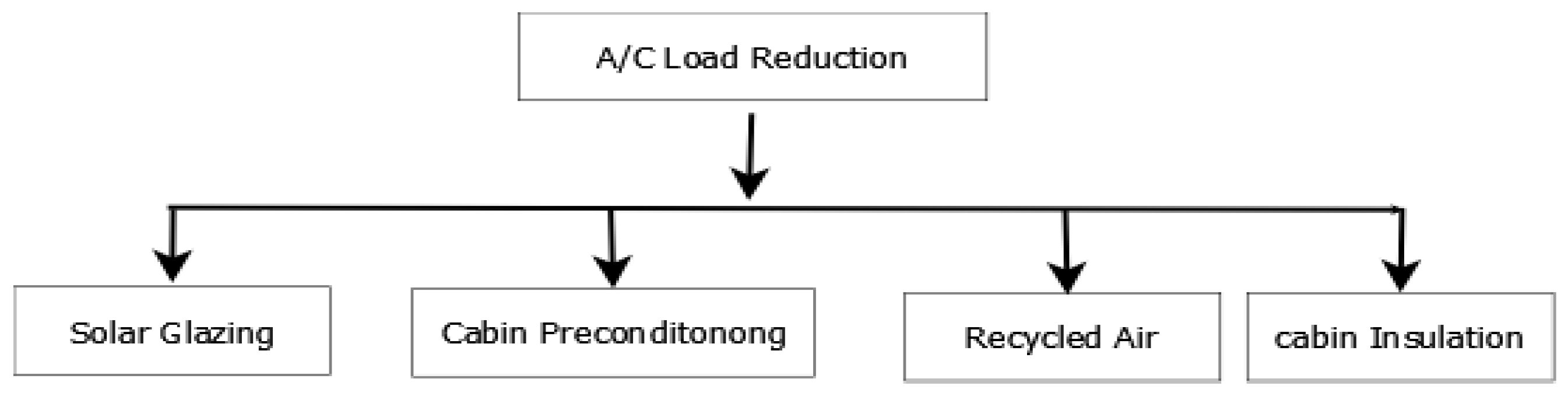
4. Air Conditioner Load Reduction
4.1. Solar-Reflective Glazing

| Sl No | Type | Effects |
|---|---|---|
| 1 | Solar-reflective glazing with a dielectric layer and silver [90] | Solar radiation was reduced by 14% Reduced compressor load by 11.3% |
| 2 | Advanced Sungate windshield [91] | Reduced the compressor power by 400 W Reduction in fuel consumption by 3.4% |
| 3 | Double panel glaze (glass and polycarbonate) coated with films [92] | 48% heat load can be reduced |
| 4 | Solar reflectivity glaze (Sungate-EP) with body insulation [93,94] | 33% thermal load can be reduced |
| 5 | Polycarbonate sheet [95,96] | 5.9–7.1% cooling load can be reduced |
| 6 | Bond of polyvinyl butyral between the glaze pieces [97] | Cabin temperature was reduced by 1 °C Air conditioner capacity was reduced by 4% Range improved by 0.7–1.5% |
| 7 | Solar intensity reduction glaze [98] | The surface temperature of the body was reduced by 2 °C Power consumption was reduced by 20% |
| 8 | 40%, 60% and 80% solar heat radiation reduction films [99] | Heat load reduction in 14%, 18% and29%, respectively Reduction in fuel consumption of 11.7%, 14.4% and 18%, respectively |
| 9 | IRR glasses and blinds [100] | Reduced the heat load |
| 10 | Photovoltachromic glazing [101,105] | Transmissibility was reduced by 75% 33% thermal load can be reduced |
4.2. Cabin Preconditioning
4.3. Recirculation Mode
4.4. Other Factors Influencing EV Range
5. Methodologies Identified
- Depending on the number of passengers, the volume of air to be conditioned can be reduced. Instead of conditioning the whole cabin space, only the surrounding space of the passengers is conditioned through localized/zonal cooling systems.
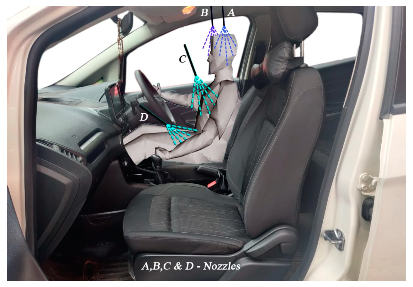
- The optimum amount of conditioned air should reach the breathing zone of the passenger at the required velocity, pressure, and temperature. The roles of the shape and position of the nozzle were considered.
5.1. Localized/Zonal Cooling
- ○
- practical limitations to control the temperature of individual occupant zone;
- ○
- the development of a thermal boundary layer around the occupant for non-thermal interaction with the rest of the cabin space;
- ○
- effective temperature control of body parts which is in contact with the seat.
- ○
- the mechanism of airflow and heat transfer through the seat;
- ○
- effective distribution of conditioned air around the body parts according to the exact requirement;
- ○
- control over the flow of conditioned air around the occupant, based on the temperature of different body parts;
- ○
- comfort condition is based on the position of the air vent; the arrangement of air vents nearby the body will restrict the moment; high-speed air circulation is needed if the vent is arranged away from the body; the speed of the circulating air is one of the deciding factors of comfort;
- ○
- airflow to the neck has to be controlled because the neck is more sensitive [99].
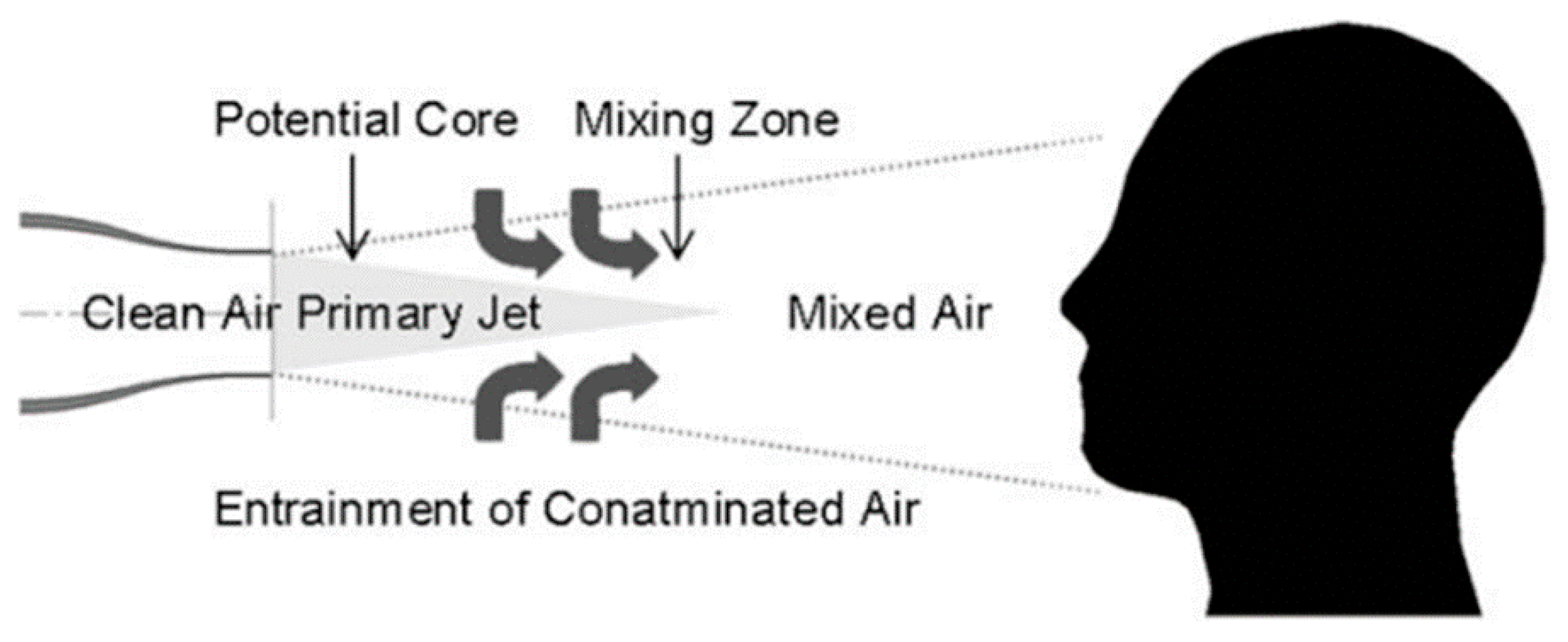
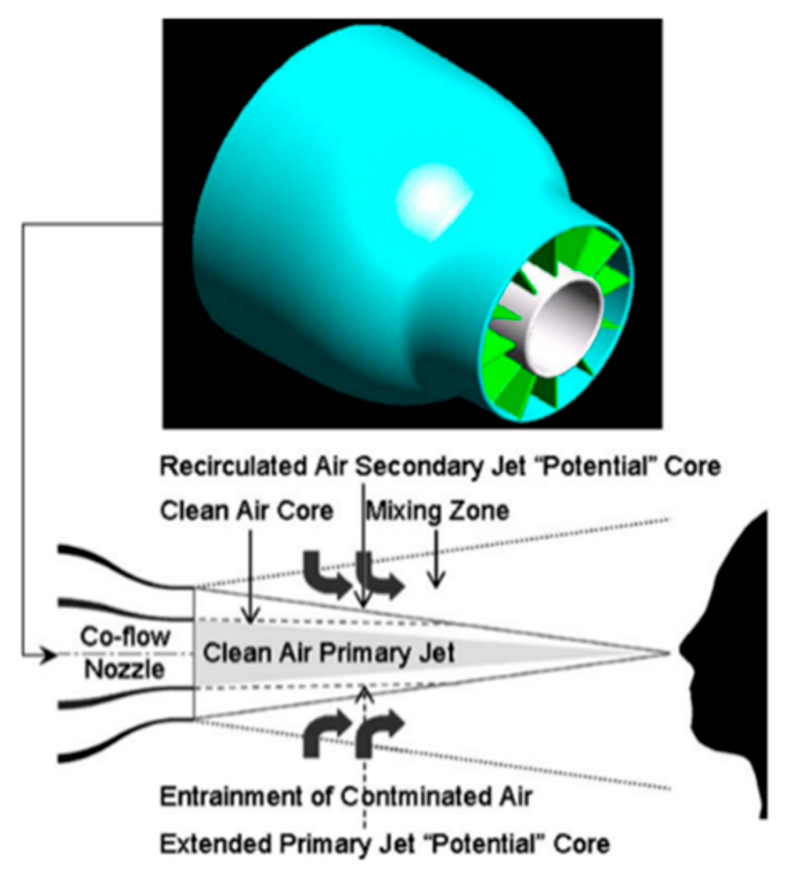
5.2. Nozzle
5.3. Nozzle Configuration
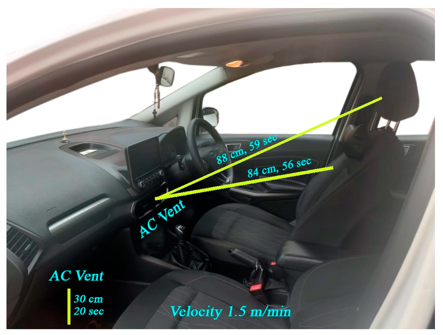
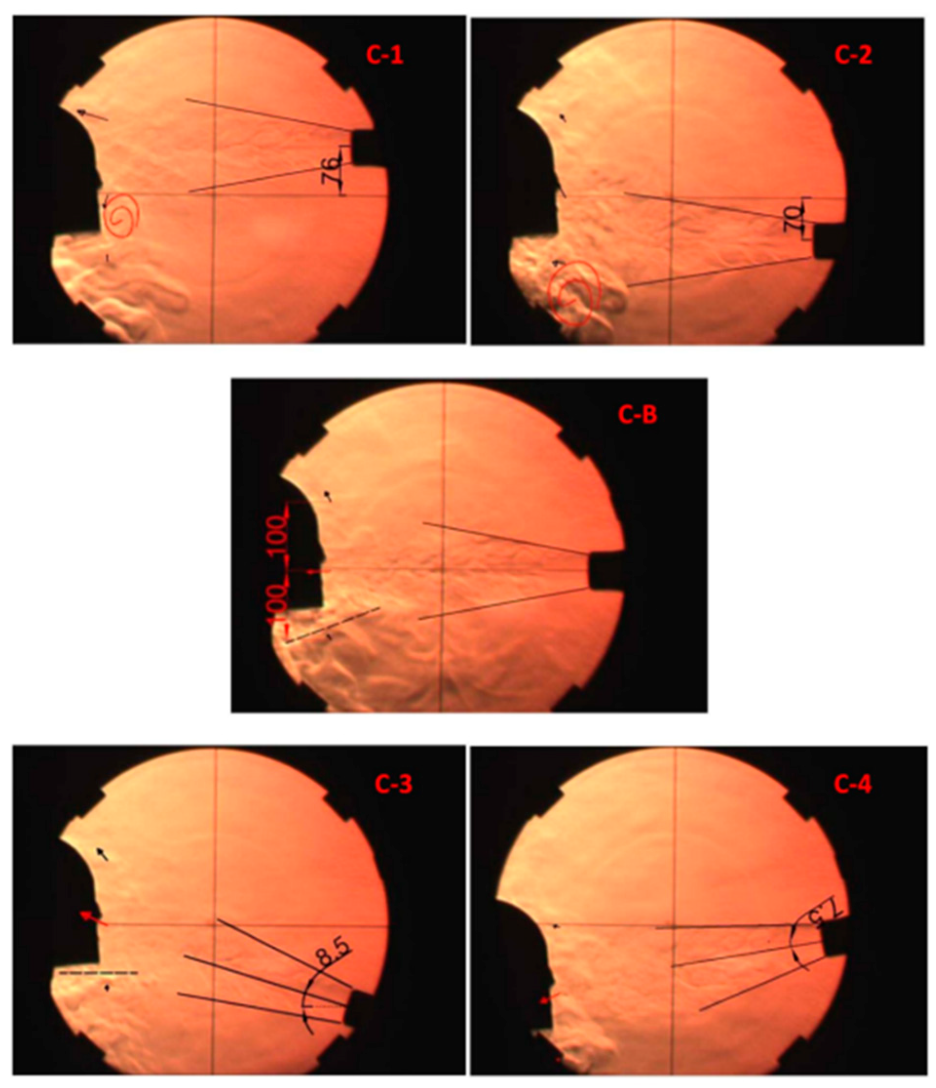
5.4. Position
6. Conclusions
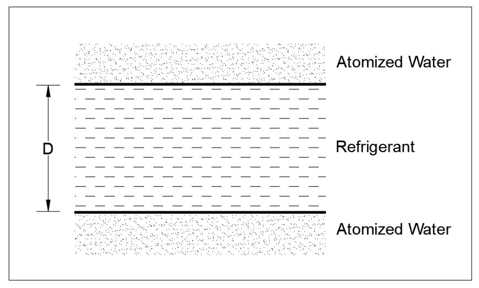
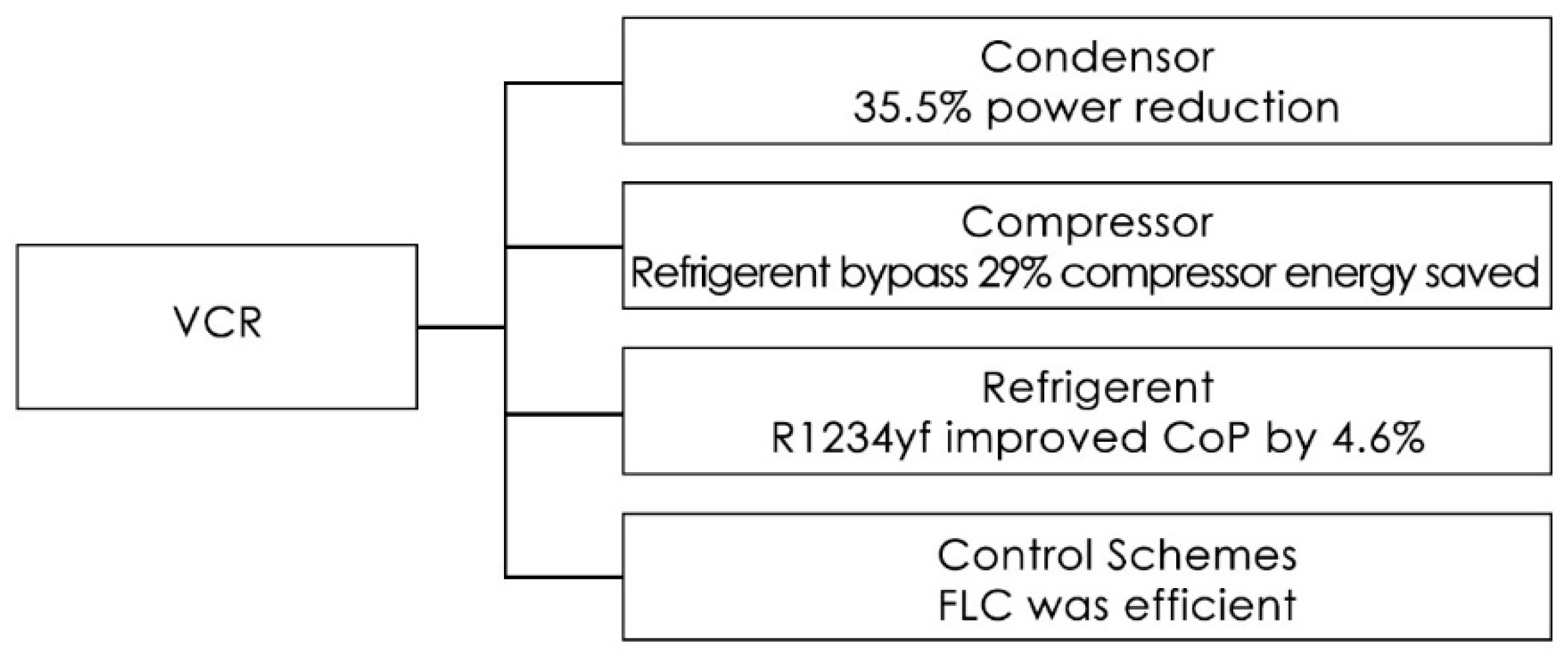
- By utilizing the condensate water, a vaporized moisture presence around the tubes of the condenser can be created to improve the heat transfer rate. Effective utilization of the condenser leads to a power reduction of 7.3–35.5%.
- The power supply controlled by the evaporator outlet temperature was reported to be the most effective. Cabin preconditioning with the help of grid power increased the range by 9.86%.
- The recirculation of cabin air leads to a power reduction of 48.8–60.8%. An optimum amount of recirculation ensures comfort.
- With the help of an effective glazing system, 11.3–48% of power consumption can be saved. A reduction in cooling load of 3.4–20% was reported.
- During idle/stationary conditions, when a battery-powered motor was used for the air conditioning system, it reduced the fuel consumption by 25–30% in the case of an IC engine vehicle.
- Battery-controlled variable displacement rotary compressors operated with the help of external control systems were developed. An effective compressor led to a power reduction of 3.3–30% compared to the IC engine-coupled compressor.
- An alternative refrigerant for R134a was studied, and CO2 and R1234yf were proposed by the researchers for extra power consumption. These refrigerants ensure environmental protection.
- Instead of circulating the conditioned air to the full cabin, systems could concentrate only on the occupant zone. This leads to a reduction in power consumption of 17.0–36.7%. These systems can also improve comfort due to individual concentration and reduced velocity of flow.
- Circular-shaped and double-cylinder type nozzles ensure the lengthy fresh air core of airflow to the breathing zone. A slightly inclined flow from the top of the cabin space to the nose provides better comfort to the passenger.
- Other methodologies were found to be less effective when compared to the above-mentioned methodologies
- the development of new refrigerants that are eco-friendly, stable and with good thermodynamic properties, and require low fuel consumption;
- alternative equipment for the compressor (such as adsorption) without any compromise on the COP;
- effective methods to reduce thermal soaking, including methods for cabin heat load reduction through the glass and shell, such as new material development that increases reflectance or arrests the heat penetration;
- the development of an automated control system to monitor and regulate the recirculated air for optimum energy consumption and comfort, and a simple mechanism to avoid the mixing of fresh air and recirculated air in the breathing zone;
- the position of the air vents to ensure a comfortable air velocity, when conditioned air reaches the human body;
- reduction in the size and weight of the system with improved performance;
- the optimization of nozzles for maximum comfort;
- the development of a digital twin for the automotive air conditioning system for diagnostics;
- practical limitations to control the temperature of the individual occupant zone;
- the development of a thermal boundary layer around the occupant for non-thermal interaction with the rest of the cabin space via the mechanism of airflow and heat transfer through the seat, including the effective distribution of conditioned air around the body parts according to the exact requirements.
Author Contributions
Funding
Institutional Review Board Statement
Informed Consent Statement
Data Availability Statement
Conflicts of Interest
Nomenclature
| °C | Degree Celsius |
| Cc | Cubic Capacity |
| D | Dia of the pipe |
| h | hour |
| km | Kilometer |
| kg | Kilogram |
| km/h | Kilometer per hour |
| L | Length |
| L/s | Litters per Second |
| MPa | Mega Pascal |
| m/s | Meter per Second |
| Nm | Newton Meter |
| ppm | parts per million |
| V | Volt |
| W | Watt |
| W/m2 | Flux |
| ANFIS | Adaptive Neuro-Fuzzy Inference System |
| ASHRAE | American Society of Heating, Refrigerating and Air Conditioning Engineers |
| ASTME | American Society of Tool and Manufacturing Engineers |
| AC | Air Conditioner |
| CCOT | Cycling Clutch Orifice Tube |
| CFD | Computational Fluid Dynamics |
| CO2 | Carbon dioxide |
| COP | Coefficient of Performance |
| DC | Direct Current |
| DSVC | Double-Swing Vane Compressor |
| EEV | Electronic Control Expansion Valve |
| EVDC | Externally Controlled Variable Displacement Compressor |
| EV | Electric Vehicle |
| FCC | Fixed Capacity Compressors |
| FDC | Fixed Displacement Compressors |
| FLC | Fuzzy Logic Control |
| GM | General Motors |
| GWP | Global Warming Potential |
| HVAC | Heating, Ventilation, and Air Conditioning |
| IC | Internal Combustion |
| IEA | International Energy Agency |
| ODP | Ozone Depletion Potential |
| PTC | Positive Temperature Coefficient |
| PV | Personalized Ventilation |
| rpm | Rotation per Minute |
| UN | United Nations |
| USA | United States of America |
| VCR | Vapor-Compression Refrigeration |
| VCC | Variable Capacity Compressors |
| ZT | Figure of Merit |
References
- Chan, C.; Chau, K. Modern Electric Vehicle Technology; Oxford University Press on Demand: New York, NY, USA, 2001. [Google Scholar]
- Roy, D.; el Khoury, K.; Clodic, D.; Petitjean, C. Modeling of in-Vehicle Heat Transfers Using Zonal Approach. SAE Int. J. 2001. [Google Scholar] [CrossRef]
- Kaushik, S.; Chen, K.; Han, T.; Khalighi, B. Micro-Cooling/Heating Strategy for Energy Efficient HVAC System. SAE Int. J. Mater. Manuf. 2011, 4, 853–863. Available online: http://www.jstor.org/stable/26273823 (accessed on 24 September 2022). [CrossRef]
- Smierciew, K.; Gagan, J.; Butrymowicz, D.; Karwacki, J. Experimental investigations of solar driven ejector air conditioning system. Energy Build. 2014, 80, 260–267. [Google Scholar] [CrossRef]
- Trust, C. Heating, Ventilation and Air Conditioning Overview Guide. 2017. Available online: https://www.carbontrust.com/resources/guides/energy-efficiency/heating-ventilation-and-airconditioning-hvac/ (accessed on 12 February 2020).
- IEA Technology Roadmap. Energy-Efficient Buildings: Heating and Cooling Equipment. 2013. Available online: https://www.iea.org/reports/technology-roadmap-energy-efficient-buildings-heating-and-cooling-equipment (accessed on 12 February 2020).
- Lee, J.T.; Kwon, S.K.; Lim, Y.S.; Chon, M.S.; Kim, D.S. Effect of Air Conditioning on Driving Range of Electric Vehicle for Various Driving Modes. SAE Int. J. 2013. [Google Scholar] [CrossRef]
- Kambly, K.R.; Bradley, T.H. Estimating the HVAC energy consumption of plug-in electric vehicles. J. Power Sources 2014, 259, 117–124. [Google Scholar] [CrossRef]
- Kiss, T.; Lustbader, J.; Leighton, D. Modeling of an Electric Vehicle Thermal Management System in MATLAB/Simulink. SAE Int. J. 2015. [Google Scholar] [CrossRef] [Green Version]
- Farrington, R.; Rugh, J. Impact of Vehicle Air Conditioning on Fuel Economy, Tailpipe Emissions, and Electric Vehicle Range; NREL/CP-540-28960; Earth Technologies Forum: Washington, DC, USA, 2000. Available online: https://www.nrel.gov/docs/fy00osti/28960.pdf (accessed on 24 September 2022).
- Shi, X.; Pan, J.; Wang, H.; Cai, H. Battery electric vehicles: What is the minimum range required? Energy 2019, 166, 352–358. [Google Scholar] [CrossRef]
- Samadani, E.; Fraser, R.; Fowler, M. Evaluation of Air Conditioning Impact on the Electric Vehicle Range and Li-Ion Battery Life. SAE Int. J. 2014. [Google Scholar] [CrossRef]
- Vashisht, S.; Rakshit, D. Recent advances and sustainable solutions in automobile air conditioning systems. J. Clean. Prod. 2021, 329, 129754. [Google Scholar] [CrossRef]
- Shah, R.K. Automotive Air Conditioning Systems—Historical Developments, the State of Technology, and Future Trends. Heat Transf. Eng. 2009, 30, 720–735. [Google Scholar] [CrossRef]
- Sukri, M.F.; Musa, M.N.; Senawi, M.Y.; Nasution, H. Achieving a better energy-efficient automotive air conditioning system: A review of potential technologies and strategies for vapor compression refrigeration cycle. Energy Effic. 2015, 8, 1201–1229. [Google Scholar] [CrossRef]
- India Cooling Action Plan, Report by Ozone Cell, Ministry of Environment, Forest & Climate Change, Government of India March 2019. Available online: http://ozonecell.nic.in/wp-content/uploads/2019/03/INDIA-COOLING-ACTION-PLAN-e-circulation-version080319.pdf (accessed on 24 September 2022).
- Chaney, L.; Thundiyil, K.; Chidambaram, S.; Abbi, Y.P.; Andersen, S. Fuel Savings and Emission Reductions from Next-Generation Mobile Air Conditioning Technology in India. In Proceedings of the Vehicle Thermal Management Systems Conference & Exhibition (VTMS-8), Nottingham, UK, 20–24 May 2007. [Google Scholar]
- Kang, B.H.; Lee, H.J. A Review of Recent Research on Automotive HVAC Systems for EVs. Int. J. Air Cond. Refrig. 2017, 25, 1730003. [Google Scholar] [CrossRef]
- Yokoyama, A.; Osaka, T.; Imanishi, Y. Thermal management system for electric vehicles. SAE Int. J. Mater. Manuf. 2011, 4, 1277–1285. Available online: https://www.jstor.org/stable/26273859 (accessed on 23 September 2022). [CrossRef]
- Kowsky, C.; Wolfe, E.; Leitzel, L.; Oddi, F. Unitary HPAC system. SAE Int. J. Passeng. Cars Mech. Syst. 2012, 5, 1016–1025. [Google Scholar] [CrossRef]
- Torregrosa-Jaime, B.; Vasile, C.; Risser, M.; Muller, C.; Corberan, J.; Paya, J. Application of magnetocaloric heat pumps in mobile air conditioning. SAE Int. J. Passeng. Cars Mech. Syst. 2013, 6, 520–528. [Google Scholar] [CrossRef]
- Wang, M.; Craig, T.; Wolfe, E.; Laclair, T.J.; Gao, Z.; Levin, M.; Danrich, D.; Furqan, S. Integration and Validation of A Thermal Energy Storage System for Electric Vehicle Cabin Heating. SAE Int. J. 2017. [Google Scholar] [CrossRef]
- Wang, M.; Wolfe, E., IV; Craig, T.; Laclair, T.J.; Gao, Z.; Abdelaziz, O. Design and Testing of A Thermal Storage System for Electric Vehicle Cabin Heating. SAE Int. J. 2016. [Google Scholar] [CrossRef]
- Qi, Z. Advances on air conditioning and heat pump system in electric vehicles—A review. Renew. Sustain. Energy Rev. 2014, 38, 754–764. [Google Scholar] [CrossRef]
- Bentrcia, M.; Alshitawi, M.; Omar, H. Developments of alternative systems for automotive air conditioning—A review. J. Mech. Sci. Technol. 2018, 32, 1857–1867. [Google Scholar] [CrossRef]
- Quick, D. Solar-Powered Air Conditioning for Vehicles, 17 November 2010. Available online: https://phys.org/news/2011-10-solar-powered-air-conditioning-vehicles.html (accessed on 23 September 2022).
- Lethwala, Y.; Garg, P. Development of auxiliary automobile air conditioning system by solar energy. Int. Res. J. Eng. Technol. 2017, 4, 737–742. Available online: www.irjet.net (accessed on 23 September 2022).
- Ingersoll, J. Integration of Solar Cells in Automobiles as a Means to Reduce the Air Conditioner Capacity and Improve Comfort; Kluwer Academic Publishers: Norwell, MA, USA, 1989. [Google Scholar]
- Pang, W.; Yu, H.; Zhang, Y.; Yan, H. Solar photovoltaic based air cooling system for vehicles. Renew. Energy 2019, 130, 25–31. [Google Scholar] [CrossRef]
- Alani, W.K.; Zheng, J.; Fayad, M.A.; Lei, L. Enhancing the fuel saving and emissions reduction of light-duty vehicle by a new design of air conditioning worked by solar energy. Therm. Eng. 2022, 30, 101798. [Google Scholar] [CrossRef]
- Lindgren, C.A. Feasibility Study of Utilizing Solar Panels to Power a Vehicle’s Onboard Air Conditioner; Rensselaer Polytechnic Institute: Hartford, CT, USA, 2012. [Google Scholar]
- Magnetto, D.; Mola, S.; DaCosta, D.H.; Golben, M.; Rosso, M. A Metal Hydride Mobile Air Conditioning System. SAE Int. J. 2006. [Google Scholar] [CrossRef]
- Amirgon Incorporated. Amerigon’s Climate Control Seat (TM) (CCS(TM)) System Offered as an Option on 2006 Cadillac DTS. 2005. Available online: https://www.amerigon.com/ (accessed on 23 August 2018).
- Maronde, C.; Maranville, C.; Gundlach, E. Automotive Thermoelectric HVAC Development and Demonstration Project; CE C-500-2016-017; National Energy Technology Laboratory, United States Department of Energy: Washington, DC, USA, 2016. Available online: https://www.osti.gov/servlets/purl/1607865 (accessed on 23 September 2022).
- Kim, J.Y.; Ahn, Y.N.; Rok, S.; Kim, S.W.; Cho, W.J.; Choi, J.; Shin, H.K.; Lee, S.O. Combined Condensing Air Conditioning System. SAE Int. J. 2014. [Google Scholar] [CrossRef]
- Zhou, D.; Tan, G.; Ma, Z.; Ding, Y.; Ma, X.; Wang, S.; Wang, H. Energy Consumption Optimization for the Electric Vehicle Air Conditioning Using the Condensate Water. SAE Int. J. 2019. [Google Scholar] [CrossRef]
- Cummings, R.W.; Shah, R.K. Experimental Performance Evaluation of Automotive Air Conditioning Heat Exchangers as Components and in Vehicle Systems. SAE Int. J. 2005. [Google Scholar] [CrossRef]
- Park, S.K.; Kim, H.; Ahn, H.; Park, H.S. Study on the Reduction of Fuel Consumption in the A/C System, Used Variable Displacement Swash-Plate Compressor and the Performance Improvement by Field Test. SAE Int. J. 2006. [Google Scholar] [CrossRef]
- Gaveau, O.; Clodic, D. Test Bench for Measuring the Energy Consumption of an Automotive Air Conditioning System. SAE Int. J. 1998. [Google Scholar] [CrossRef]
- Dahlan, A.A.; Zulkifli, A.H.; Nasution, H.; Aziz, A.A.; Perang, M.R.M.; Jamil, H.M.; Zulkifli, A.A. Efficient and ‘Green’ Vehicle Air Conditioning System using Electric Compressor. Energy Procedia 2014, 61, 270–273. [Google Scholar] [CrossRef] [Green Version]
- Tian, C.; Dou, C.; Yang, X.; Li, X. Instability of automotive air conditioning system with a variable displacement compressor. Part 1. Experimental investigation. Int. J. Refrig. 2005, 28, 1102–1110. [Google Scholar] [CrossRef]
- Tian, C.; Li, X. Transient behavior evaluation of an automotive air conditioning system with a variable displacement compressor. Appl. Therm. Eng. 2005, 25, 1922–1948. [Google Scholar] [CrossRef]
- Watanabe, Y.; Sekita, M.; Miura, S. Saving Power by Demand Capacity Controlled Compressor. SAE Int. J. 2002. [Google Scholar] [CrossRef]
- Alkan, A.; Hosoz, M. Comparative performance of an automotive air conditioning system using fixed and variable capacity compressors. Int. J. Refrig. 2010, 33, 487–495. [Google Scholar] [CrossRef]
- Tian, C.; Liao, Y.; Li, X. A mathematical model of variable displacement swash plate compressor for automotive air conditioning system. Int. J. Refrig. 2005, 29, 270–280. [Google Scholar] [CrossRef]
- Wang, M.; Zima, M.J.; Kadle, P.S. Energy-Efficient Air Conditioning Systems Utilizing Pneumatic Variable Compressors. SAE Int. J. 2009. [Google Scholar] [CrossRef]
- Qi, Z.; Chen, J.; Chen, Z.; Hu, W.; He, B. Experimental study of an auto-controlled automobile air conditioning system with an externally-controlled variable displacement compressor. Appl. Therm. Eng. 2007, 27, 927–933. [Google Scholar] [CrossRef]
- Yang, X.; Dong, C.; Qu, Z. Design and dynamic analysis of a novel double-swing vane compressor for electric vehicle air conditioning systems. Int. J. Refrig. 2017, 76, 52–62. [Google Scholar] [CrossRef] [Green Version]
- Jang, K.; Jeong, S. Experimental investigation on convective heat transfer mechanism in a scroll compressor. Int. J. Refrig. 2006, 29, 744–753. [Google Scholar] [CrossRef]
- Srinivasan, D.; Phadke, P. Reducing ac power consumption by compressor downsizing on a sports utility vehicle. In Proceedings of the International Refrigeration and Air Conditioning Conference, West Lafayette, IN, USA, 17–20 July 2006; p. 844. Available online: http://docs.lib.purdue.edu/iracc/844 (accessed on 25 August 2018).
- Kapoor, S.H.; Paramane, S.; Arora, G. Application of energy efficient scroll compressor for small cars. In Proceedings of the International Refrigeration and Air Conditioning Conference at Purdue, West Lafayette, IN, USA, 12–15 July 2004. [Google Scholar]
- Perevozchikov, M.M.; Pham, H.M. Scroll compressor for mobile HVAC/R application. In Proceedings of the International Compressor Engineering Conference at Purdue, West Lafayette, IN, USA, 12–15 July 2004. [Google Scholar]
- Cuevas, C.; Fonseca, N.; Lemort, V. Automotive electric scroll compressor: Testing and modeling. Int. J. Refrig. 2012, 35, 841–849. [Google Scholar] [CrossRef]
- Nam, D.; Lee, P.; Lee, G.; Kwon, Y.; Lee, J. Optimization of an oil charge amount on electric driven scroll compressor for eco-friendly vehicle. Int. J. Refrig. 2015, 57, 54–61. [Google Scholar] [CrossRef]
- Akpobi, J.A.; Ajayi, O.I. Design and Construction of a Scroll Compressor of an Automobile Air Conditioning System. J. Appl. Sci. Environ. Manag. 2007, 11, 33–41. [Google Scholar] [CrossRef]
- Akabane, H.; Ikeda, S.; Kikuchi, K.; Tamura, Y.; Sakano, R.; Bessler, W.; Harms, H. Evaluation of An Electrically Driven Automotive Air Conditioning System Using A Scroll Hermetic Compressor with A Brushless DC Motor. SAE Int. J. 1989. [Google Scholar] [CrossRef]
- Ikeda, S.; Yoshii, Y.; Tamura, Y. Air Conditioning Electric Vehicles with an Electronically Driven Variable Speed Scroll Type Compressor. SAE Int. J. 1990. [Google Scholar] [CrossRef]
- Makino, M.; Ogawa, N.; Abe, Y.; Fujiwara, Y. Automotive Air Conditioning Electrically Driven Compressor. SAE Int. J. 2003. [Google Scholar] [CrossRef]
- Baumgart, R.; Aurich, J.; Ackermann, J.; Danzer, C. Comparison and Evaluation of a New Innovative Drive Concept for the Air Conditioning Compressor of Electric Vehicles. SAE Int. J. 2015. [Google Scholar] [CrossRef] [Green Version]
- Venkatarathnamand, G.; Murthy, S.S. Refrigerants for Vapour Compression Refrigeration Systems. Gen. Artic. 2012, 17, 139–162. [Google Scholar] [CrossRef]
- Tribological Studies on Scuffing Due to the Influence of Carbon Dioxide Used as a Refrigerant in Compressors. Available online: https://www.tandfonline.co (accessed on 23 September 2022).
- Brown, J.S.; Yana-Motta, S.F.; Domanski, P.A. Comparative analysis of an automotive air conditioning systems operating with CO2 and R134a. Int. J. Refrig. 2002, 25, 19–32. [Google Scholar] [CrossRef]
- Zietlow, D.; Sharma, A.; Meyer, J. An experimental study of power reduction opportunities for automotive air conditioning systems. In Proceedings of the 20th International Congress of Refrigeration, Sydney, Australia, 19–24 September 1999. [Google Scholar]
- Lee, M.; Lee, D. Review on Conventional Air Conditioning, Alternative Refrigerants, and CO2 Heat Pumps for Vehicles. HindawiPubl. Corp. Adv. Mech. Eng. 2013, 2013, 713924. [Google Scholar] [CrossRef]
- Cho, H.; Leeand, H.; Park, C. Performance characteristics of an automobile air conditioning system with internal heat exchanger using refrigerant R1234f. Appl. Therm. Eng. 2013, 61, 563–569. [Google Scholar] [CrossRef]
- Devecioglu, A.G.; Oruc, V. An analysis on the comparison of low GWP refrigerants to alternatively use in mobile air conditioning systems. Therm. Sci. Eng. Prog. 2017, 1, 1–5. [Google Scholar] [CrossRef]
- Meng, Z.; Zhang, H.; Lei, M.; Qin, Y.; Qiu, J. Performance of low GWP R1234yf/R134a mixture as a replacement for R134a in automotive air conditioning systems. Int. J. Heat Mass Transf. 2018, 116, 362–370. [Google Scholar] [CrossRef]
- Liu, Z.; Wang, X. Effect of Magnetic Nano-Refrigerant on Electric Vehicle. SAE Int. J. 2017. [Google Scholar] [CrossRef]
- Zhang, Z.; Wang, J.; Feng, X.; Chang, L.; Chen, Y.; Wang, X. The solutions to electric vehicle air conditioning systems: A review. Renew. Sustain. Energy Rev. 2018, 91, 443–463. [Google Scholar] [CrossRef]
- Yu, B.; Wang, D.; Liu, C.; Jiang, F.; Shi, J.; Chen, J. Performance improvements evaluation of an automobile air conditioning system using CO2-propane mixture as a refrigerant. Int. J. Refrig. 2018, 88, 172–181. [Google Scholar] [CrossRef]
- Li, X.; Chen, J.; Chen, Z.; Liu, W.; Hu, W.; Liu, X. A new method for controlling flow in automobile air conditioning. Appl. Therm. Eng. 2004, 24, 1073–1085. [Google Scholar] [CrossRef]
- Feng, L.; Hrnjak, P. Experimental Study of an Air Conditioning-Heat Pump System for Electric Vehicles. SAE Int. J. 2016. [Google Scholar] [CrossRef]
- Surampudi, B.; Redfield, J.; Montemayor, A.; Ray, G.; Ostrowski, G.; McKee, H.; Edwards, T.; Carstensen, A.S.; Lawraence, J.C. Electric Air Conditioning for Class 8 Tractors. SAE Int. J. 2006. [Google Scholar] [CrossRef] [Green Version]
- Al-Jarrah, R.; Al-Jarrah, M.A. Developed adaptive neuro-fuzzy algorithm to control air conditioning system at different pressures. Int. J. Eng. Sci. Technol. 2013, 5, 43–59. [Google Scholar] [CrossRef] [Green Version]
- Singh, J.; Singh, N.; Sharma, J.K. Fuzzy modeling and control of HVAC—A review. J. Sci. Ind. Res. 2002, 65, 470–476. [Google Scholar]
- Nasution, H. Development of fuzzy logic control for vehicle air conditioning system. Telecommun. Comput. Electron. Control 2008, 6, 73–82. [Google Scholar] [CrossRef] [Green Version]
- Weng, C.-H.; Kau, L. Design and Implementation of a Low-Energy-Consumption Air Conditioning Control System for Smart Vehicle. J. Healthc. Eng. 2019, 14, 3858560. [Google Scholar] [CrossRef] [PubMed] [Green Version]
- Budiman, F.; Rivai, M.; Raditya, I.G.B.P.; Krisrenanto, D.; Amiroh, I.Z. Smart Control of Air Conditioning System Based on Number and Activity Level of Persons. In Proceedings of the 2018 International Seminar on Intelligent Technology and Its Applications (ISITIA), Bali, Indonesia, 30–31 August 2018. [Google Scholar] [CrossRef]
- Al-Ghasem, A.; Ussaleh, N. Air Conditioner Control Using Neural Network and PID Controller. In Proceedings of the 2012 8th International Symposium on Mechatronics and its Applications, Sharjah, United Arab Emirates, 10–12 April 2012. [Google Scholar] [CrossRef]
- Attia, A.; Rezeka, S.F.; Saleh, A.M. Fuzzy logic control of air conditioning system in residential buildings. Alex. Eng. J. 2015, 54, 395–403. [Google Scholar] [CrossRef] [Green Version]
- Komatsu, Y.; Hamada, K.; Nukaga, N.; Ueda, T.K.Y.; Matsubara, E.; Jinno, N. Area detection technology for Air Conditioner. In Proceedings of the 2015 54th Annual Conference of the Society of Instrument and Control Engineers of Japan (SICE), Hangzhou, China, 28–30 July 2015. [Google Scholar] [CrossRef]
- Lee, J.; Kim, J.; Park, J.; Bae, C. Effect of the air conditioning system on the fuel economy in a gasoline engine vehicle. Proc. Inst. Mech. Eng. Part D J. Automob. Eng. Jan. 2013, 227, 66–77. [Google Scholar] [CrossRef]
- Huff, S.; West, B.; Thomas, J. Effects of Air Conditioner Use on Real-World Fuel Economy. SAE Int. J. Paper 2013-01-0551. [CrossRef]
- Dieckmann, J.; Mallory, D. Variable Speed Compressor, HFC-134a Based Air Conditioning System for Electric Vehicles; SAE Technical Paper No. 920444; SAE: Warrendale, PA, USA, 1992. [Google Scholar] [CrossRef]
- Warule, P.B.; Jadhav, V.V. Optimization of AC Control in Hybrid Electric Vehicles during Urban Drive Conditions. SAE Int. J. 2017. [Google Scholar] [CrossRef]
- Torregrosa-Jaime, B.; Paya, J.; Corberan, J. Design of Efficient Air Conditioning Systems for Electric Vehicles. SAE Int. J. 2013. [Google Scholar] [CrossRef]
- Zhang, Q.; Meng, Y.; Greiner, C.; Soto, C.; Schwartz, W.; Jennings, M. Air Conditioning System Performance and Vehicle Fuel Economy Trade-Offs for A Hybrid Electric Vehicle. SAE Int. J. 2017. [Google Scholar] [CrossRef]
- Adhikari, V.P.; Nasser, A.; Nagpurwala, Q.H. Numerical Studies on the Effect of Cooling Vent Setting and Solar Radiation on Air Flow and Temperature Distribution in A Passenger Car. SAE Int. J. 2009. [Google Scholar]
- Lin, P. Performance evaluation and analysis of EV air conditioning system. World Electr. Veh. J. 2010, 4, 197–201. [Google Scholar] [CrossRef]
- Rugh, J.P.; Hendricks, T.J.; Koram, K. Effect of Solar Reflective Glazing on Ford Explorer Climate Control, Fuel Economy, and Emissions. SAE Int. J. 2001. Available online: https://www.sae.org/publications/technical-papers/content/2001-01-3077/ (accessed on 23 August 2019).
- Farrington, R.B.; Rugh, J.P.; Barber, G.D. Effect of Solar-Reflective Glazing on Fuel Economy, Tailpipe Emissions, and Thermal Comfort. SAE Int. J. 2000. [Google Scholar] [CrossRef] [Green Version]
- Türler, D.; Hopkins, D.; Goudey, H. Reducing Vehicle Auxiliary Loads Using Advanced Thermal Insulation and Window Technologies. SAE Int. J. 2003. [Google Scholar] [CrossRef]
- Han, T.; Chen, K. Assessment of Various Environmental Thermal Loads on Passenger Compartment Soak and Cool-Down Analyses. SAE Int. J. 2009. Available online: https://www.sae.org/publications/technical-papers/content/2009-01-1148/ (accessed on 23 September 2022).
- Han, T.; Chen, K.; Khalighi, B.; Curran, A.; Pryor, J.; Hepokoski, M. Assessment of Various Environmental Thermal Loads on Passenger Thermal Comfort. SAE Int. J. Passeng. Cars 2010, 3, 830–841. [Google Scholar] [CrossRef]
- Gasworth, S.; Tankala, T.; Kancharla, A.; Shuler, S. Improved Battery Performance in Electric Vehicles via Reduced Glazing Thermal Conductivity. SAE Int. J. 2011. [Google Scholar] [CrossRef]
- Gasworth, S.; Tankala, T. Reduced Steady State Heating and Air Conditioning Loads via Reduced Glazing Thermal Conductivity. SAE Int. J. 2011. [Google Scholar] [CrossRef]
- Rugh, J.; Chaney, L.; Ramroth, L.; Venson, T.; Rose, M. Impact of Solar Control PVB Glass on Vehicle Interior Temperatures, Air Conditioning Capacity, Fuel Consumption, and Vehicle Range. SAE Int. J. 2013. [Google Scholar] [CrossRef] [Green Version]
- Ozeki, Y.; Harita, Y.; Hirano, A.; Nishihama, J. Evaluation on the Solar Reduction Glass in an Electric Vehicle by Experimental Measurements in A Climate Chamber. SAE Int. J. 2014. [Google Scholar] [CrossRef]
- Danca, P.; Vartires, A.; Dogeanu, A. An overview of current methods for thermal comfort assessment in vehicle cabin. Energy Procedia 2016, 85, 162–169. [Google Scholar] [CrossRef] [Green Version]
- Kandasamy, N.; Kota, K.N.; Joshi, P. Numerical Evaluation of Vehicle Orientation and Glazing Material Impact on Cabin Climate and Occupant Thermal Comfort. SAE Int. J. 2017. [Google Scholar] [CrossRef]
- Jaksic, N.I.; Salahifar, C. A feasibility study of electrochromic windows in vehicles. Sol. Energy Mater. Sol. Cells 2003, 79, 409–423. [Google Scholar] [CrossRef]
- Marshall, G.J.; Mahony, C.P.; Rhodes, M.J.; Daniewicz, S.R.; Tsolas, N.; Thompson, S.M. Thermal Management of Vehicle Cabins, External Surfaces, and Onboard Electronics: An Overview. Engineering 2019, 5, 954–969. [Google Scholar] [CrossRef]
- Levinson, R.; Pan, H.; Ban-Weiss, G.; Rosado, P.; Paolini, R.; Akbari, H. Potential benefits of solar reflective car shells: Cooler cabins, fuel savings and emission reductions. Appl. Energy 2011, 88, 4343–4357. [Google Scholar] [CrossRef] [Green Version]
- Hoke, P.B.; Greiner, C. Vehicle Paint Radiation Properties and Affect on Vehicle Soak Temperature, Climate Control System Load, and Fuel Economy; SAE World Congress: Detroit, MI, USA, 2005. [Google Scholar] [CrossRef]
- Jha, K.K.; Bhanot, V.; Ryali, V. A Simple Model for Calculating Vehicle Thermal Loads. SAE Int. J. 2013. [Google Scholar] [CrossRef]
- Zheng, Y.; Mark, B.; Youmans, H. A Simple Method to Calculate Vehicle Heat Load. SAE Int. J. 2011. [Google Scholar] [CrossRef]
- Zhai, Y.; Ma, Y.; David, S.N.; Zhao, D.; Lou, R.; Tan, G.; Yang, R.; Yin, X. Scalable-manufactured randomized glass-polymer hybrid metamaterial for daytime radiative cooling. Science 2017, 355, 1062–1066. [Google Scholar] [CrossRef] [Green Version]
- Kambly, K.; Bradley, T.H. Geographical and temporal differences in electric vehicle range due to cabin conditioning energy consumption. J. Power Sources 2015, 275, 468–475. [Google Scholar] [CrossRef]
- Rugh, J.P.; Chaney, L.; Lustbader, J. Reduction in Vehicle Temperatures and Fuel Use from Cabin Ventilation, Solar-Reflective Paint, and a New Solar-Reflective Glazing. SAE Int. J. 2007. Available online: https://www.sae.org/publications/technical-papers/content/2007-01-1194/ (accessed on 23 September 2022).
- Rugh, J.; Farrington, R. Vehicle ancillary load reduction project close-out report. In An Overview of the Task and A Compilation of the Research Results; No.: NREL/TP-540-42454; National Renewable Energy Laboratory: Washington, DC, USA, 2008. [Google Scholar]
- Suzuki, T.; Ishii, K. Air Conditioning System for Electric Vehicle; SAE Technical Paper Series; SAE: Warrendale, PA, USA, 1996; p. 960688. [Google Scholar] [CrossRef]
- Hirai, S.; Kataoka, T.; Kumada, T.; Goto, T. The Humidity Control System Applied to Reduce Ventilation Heat Loss of HVAC Systems. SAE Int. J. 2011. [Google Scholar] [CrossRef]
- Jackson, W.H. The Physiological Aspects of Automotive Heating, Ventilating, and Air Conditioning, General Motors. Eng. J. 1961, 1961, 2–6. [Google Scholar]
- Forrest, W.O.; Bhatti, M.S. Energy Efficient Automotive Air Conditioning System. SAE Int. J. 2002. [Google Scholar] [CrossRef]
- Pan, L.; Liu, C.; Zhang, Z.; Wang, T.; Shi, J.; Chen, J. Energy-saving Effect of Utilizing Recirculated Air in Electric Vehicle Air Conditioning System. Int. J. Refrig. 2019, 102, 122–129. [Google Scholar] [CrossRef]
- de Gennaro, M.; Paffumi, E.; Martini, G.; Manfredi, U.; Scholz, H.; Lacher, H.; Kuehnelt, H.; Simic, D. Experimental Investigation of the Energy Efficiency of an Electric Vehicle in Different Driving Conditions. SAE Int. J. 2014. [Google Scholar] [CrossRef]
- Leighton, D. Combined Fluid Loop Thermal Management for Electric Drive Vehicle Range Improvement. SAE Int. J. 2015. [Google Scholar] [CrossRef] [Green Version]
- Gowri, V.; Slezak, L.; Anderson, D. Ambient Temperature (20° F, 72° F and 95° F) Impact on Fuel and Energy Consumption for Several Conventional Vehicles, Hybrid and Plug-In Hybrid Electric Vehicles and Battery Electric Vehicle. SAE Int. J. 2013. [Google Scholar] [CrossRef]
- Mruzek, M.; Gajdac, I.; Kucera, L.; Barta, D. Analysis of Parameters Influencing Electric Vehicle Range. Procedia Eng. 2016, 134, 165–174. [Google Scholar] [CrossRef] [Green Version]
- Torregrosa-Jaime, B.; Payá, J.; Corberán, J.M. Application of magnetic cooling in electric vehicles. Sci. Technol. Built. Environ. 2016, 22, 544–555. [Google Scholar] [CrossRef] [Green Version]
- Kontakiotis, A.K.; Andwari, A.M.; Pesyridis, A.; Russo, S.; Tuccillo, R.; Esfahanian, V. Application of micro gas turbine in range extended electric vehicles. Energy 2014, 147, 351–361. [Google Scholar] [CrossRef]
- Kwon, C.; Lee, C.W.; Foster, L.; Kwon, J.; Shin, Y. Development of an Energy-Saving Occupied-Zone HVAC System (OZ HVAC). SAE Int. J. 2012. [Google Scholar] [CrossRef]
- Subiantoro, A.; Kim, T.O.; Stimming, U. Energy Saving Measures for Automotive Air Conditioning (AC). Available online: https://engineering.purdue.edu/Herrick/Events/orderlit.html (accessed on 23 September 2022).
- Melikov, A.K.; Zhou, G. Air movement at the neck of the human body. In Proceedings of the Indoor Air ‘96, Nagoya, Japan, 21–26 July 1996; pp. 209–214. [Google Scholar]
- Niu, J.; Gao, N.; Phoebe, M.; Huigang, Z. Experimental study on a chair-based personalized ventilation system. Build. Environ. 2007, 42, 913–925. [Google Scholar] [CrossRef]
- Ruzic, D.; Casnji, F. Personalized Ventilation Concept in Mobile Machinery Cab. Available online: https://www.researchgate.net/publication/263859530 (accessed on 23 September 2022).
- Dalewski, M.; Melikov, A.K.; Vesely, M. Performance of ductless personal ventilation in conjunction with displacement ventilation; physical environment and human response. Build. Environ. 2014, 81, 354–364. [Google Scholar] [CrossRef]
- Wang, M.; Ghosh, D.; Wolfe, E.; Chen, K.; Bozeman, J. Energy Efficiency Impact of Localized Cooling. SAE Int. J. 2014. Available online: https://www.sae.org/publications/technical-papers/content/2014-01-0695/ (accessed on 23 September 2022).
- Ghosh, D.; Wang, M.; Wolfe, E.; Chen, K.; Kaushik, S.; Han, T. Energy Efficient HVAC System with Spot Cooling in An Automobile—Design and CFD Analysis. SAE Int. J. 2012. Available online: https://www.sae.org/publications/technical-papers/content/2012-01-0641/ (accessed on 23 September 2022).
- Nagano, H.; Miyamoto, I.; Kohri, I. Numerical Analysis of Energy Efficiency of Zone Control Air Conditioning System for Electric Vehicle Using Numerical Manikin. SAE Int. J. 2013. [Google Scholar] [CrossRef]
- Wang, M.; Wolfe, E.; Ghosh, D.; Bozeman, J.; Chen, K.; Han, T.; Zhang, H.; Arens, E. Localized Cooling for Human Comfort. SAE Int. J. 2014. [Google Scholar] [CrossRef] [Green Version]
- Jeffers, M.A.; Chaney, L.; Rugh, J.P. Climate Control Load Reduction Strategies for Electric Drive Vehicles in Warm Weather. SAE Int. J. 2015. [Google Scholar] [CrossRef] [Green Version]
- Chen, K.; Bozeman, J.; Wang, M.; Ghosh, D.; Wolfe, E.; Chowdhury, S. Energy Efficiency Impact of Localized Cooling/Heating for Electric Vehicle. SAE Int. J. 2015. [Google Scholar] [CrossRef] [Green Version]
- Subiantoro, A.; Ooi, K.T.; Stimming, U. Energy saving measures for automotive air conditioning (AC) system in the tropics. In Proceedings of the International Refrigeration and Air Conditioning Conference, West Lafayette, IN, USA, 14–17 July 2014; p. 1361. Available online: http://docs.lib.purdue.edu/iracc/1361 (accessed on 23 September 2022).
- Oh, M.S.; Ahn, J.H.; Kim, D.W.; Jang, D.S.; Kim, Y. Thermal comfort and energy saving in a vehicle compartment using a localized air conditioning system. Appl. Energy 2014, 133, 14–21. [Google Scholar] [CrossRef]
- Fountain, M.; Arens, E.; de Dear, R.; Bauman, F.; Miura, K. Locally Controlled Air Movement Preferred in Warm Isothermal Environments. Available online: https://escholarship.org/uc/item/0f2524sk (accessed on 23 September 2022).
- Shahzad, S.; Calautit, J.K.; Calautit, K.; Hughes, B.; Aquino, A.I. Advanced personal comfort system (APCS) for the workplace: A review and case study. Energy Build. 2018, 173, 689–709. [Google Scholar] [CrossRef] [Green Version]
- Kalmar, F.; Kalmar, T. Alternative personalized ventilation. Energy Build. 2013, 65, 37–44. [Google Scholar] [CrossRef]
- Vesely, M.; Zeiler, W. Personalized conditioning and its impact on thermal comfort and energy performance—A review. Renew. Sustain. Energy Rev. 2014, 34, 401–408. [Google Scholar] [CrossRef] [Green Version]
- Luo, M.; Arens, E.; Zhang, H.; Ghahramani, A.; Wang, Z. Thermal comfort evaluated for combinations of energy-efficient personal heating and cooling devices. Build. Environ. 2018, 143, 206–216. [Google Scholar] [CrossRef] [Green Version]
- al Assaad, D.; Habchi, C.; Ghali, K.; Ghaddar, N. Effectiveness of intermittent personalized ventilation in protecting occupantfrom indoor particles. Build. Environ. 2018, 128, 22–32. [Google Scholar] [CrossRef]
- Schiavon, S.; Melikov, A.K.; Sekar, C. Energy analysis of personalized ventilation system in hot and humid climate. Energy Build. 2010, 42, 699–707. [Google Scholar] [CrossRef]
- Zhai, Z.; Metzger, I.D. Engineering Advance Insights on critical parameters and conditions for personalized ventilation. Sustain. Cities Soc. 2019, 48, 101584. [Google Scholar] [CrossRef]
- EzzatKhalifa, H.; Janos, M.I.; Dannenhoffer, J.F. Experimental investigation of reduced-mixing personal ventilation jets. Build. Environ. 2009, 44, 1551–1558. [Google Scholar] [CrossRef]
- Xu, C.; Nielsenb, P.V.; Liu, L.; Jensen, R.L.; Gong, G. Impacts of airflow interactions with thermal boundary layer on performance of personalized ventilation. Build. Environ. 2018, 135, 31–41. [Google Scholar] [CrossRef]


| Sl No | Type | Power Reduction |
|---|---|---|
| 1 | Combined water- and air-cooled [35] | 7.5% |
| 2 | A moist layer surrounds the tubes [36] | 35.5% |
| Condenser Type | Operation | Advantages | Disadvantages |
|---|---|---|---|
| Combined air-and water-cooled [35] | First, water cooling; then, air cooling |
| A separate circuit is required for the water-cooling system Weight is high due to the presence of a separate water-cooling system |
| A moist layer surrounded the condenser tubes [36] | Atomized water is circulated through the condensing tube |
| A separate system is required for atomization The presence of water has to be ensured Extra power is required for the atomization of water and circulation of mister |
| Sl No | Arrangement | Effect |
|---|---|---|
| 1 | Refrigerant by-pass and controlled air circulated through the evaporator [42] | 29% of compressor energy saved |
| 2 | Scrolltype with sinusoidal inverter [48,49,50,51,54,59] | Efficiency improved by 7% 24–30% power saving compared to reciprocating compressor Low power consumption |
| 3 | Variable-capacity compressor [44,45] | Continuous and smooth operation with good fuel economy |
| 4 | Electric-driven instead of engine-driven compressor [41] | Fuel consumption reduced from 3.03 to 14.69% |
| 5 | Two motors are placed coaxially for the vehicle and AC [59] | Range increased by 8.2% |
| 6 | Double-swing vane compressor [53,54] | Increased mechanical efficiency of 92.8% at 3000 rpm |
| 7 | Externally controlled variable displacement compressor [47] | Steady output properties (temperature and pressure), irrespective of the ambient conditions |
| Type of Compressor | Advantages |
|---|---|
| Scroll-type compressor compared with reciprocating compressor [13] | Reduced fuel consumption of 24–30% reciprocating compressor Smooth compression process Re-expansion chances are less Less frictional losses Good temperature distribution in the compressor High reliability and efficiency Light in weight, and compact |
| Variable swash plate to fixed swash plate [13] | 6.1–8.6% reduction in fuel consumption in variable swash plate compared to fixed swash plate compressor |
| Electric-driven compressor instead of an engine-driven compressor [40] | Reduced the power consumption, 3.03–14.69% Maintenance and installation are easy Ensured stability in mass flow |
| Variable capacity compressors to fixed capacity compressors [42] | Reduced hunting of the engine Fast response to the cooling demand Reduced fuel consumption Smooth starting |
| Demand capacity-controlled compressor [43] | External controller used to control the amount of the refrigerant 29% compressor power saved 22% fuel savings Temperature fluctuation was reduced by 37%. |
| Externally controlled variable displacement compressor (EVDC) [47] | Steady output properties (temperature and pressure) Sudden response to the variations of outside conditions |
| Hermetic scroll compressor [56,57] | Improved volumetric efficiency Compressor useless energy |
| Sinusoidal inverter scroll compressor [58] | Efficiency improvement of up to 7% Light in weight Reduced noise and vibration Volume was reduced by 17% |
| Efficient synergy drive [59] | The range of the vehicle was increased by 8.2% |
| Refrigerant | Fuel Consumption for Operation | Fuel Consumption to Carry the AC System in Liters |
|---|---|---|
| R744 | 133.62 | 17.03 |
| R134a | 77.6 | 11.35 |
| Particulars of Heat Load | Heat Load Details based on the Data [105] | Heat Load Details based on the Data [106] | Self-Calculated Average Sized SUV Car | Heat Load Details based on the Data [107] | |||
|---|---|---|---|---|---|---|---|
| Load (kW) | Percentage | Load (W) | Percentage | Load (W) | Percentage | Percentage | |
| Metabolic heat load | 0.24 | 5.6 | 0.852 | 12.8 | 0.116 | 2.2 | --- |
| Blower heat load | 0.21 | 4.9 | 0.202 | 3.8 | --- | ||
| Infiltration heat load | 0.71 | 16.6 | 0.808 | 12.1 | 0.571 | 10.6 | 10 |
| Shell heat load | 0.87 | 20.3 | 2.512 | 37.7 | 1.573 | 29.3 | 48 |
| Glass heat load | 2.25 | 52.6 | 2.486 | 37.3 | 2.900 | 54.1 | 42 |
| Total | 4.28 | 100 | 6.658 | 100 | 5.364 | 100 | 100 |
| Sl No | Operation | Effect |
|---|---|---|
| 1 | Cabin preconditioning [108] | Improve the range by 9.86% |
| 2 | Solar Air conditioning with photovoltaic cells [28] | Up to 40% cooling load on the battery can be reduced |
| 3 | Metal hydride air conditioning [32] | Uses only 1/3rd of electrical energy compared to the conventional vapor-compression system |
| 4 | Hybrid of electric and IC engine; electric motor used in ideal conditions [86] | Fuel economy was improved by 25–30% |
| 5 | Thermoelectric system [34] | More effective in zonal air conditioning systems |
| 6 | Electronic control expansion valve [15,71] | 3 °C temperature difference can be achieved |
| Sl No | Body Parts | Thermal Sensation |
|---|---|---|
| 1 | Back, pelvis, and chest [126] | High |
| 2 | Head, legs, andarms [126] | Medium |
| 3 | Feet and hands [126] | Low |
| Sl No | Arrangement | Changes Produced |
|---|---|---|
| 1 | Increased exit temperature by arranging the nozzle nearby the passenger (20 to 24 °C) [123] | 22% Power saved |
| 2 | Increased exit temperature (24 to 28 °C) in PV [134] | 51% Power saved |
| 3 | Three nozzles nearby the steering wheel and one nozzle near the headrest and one along with the seatbelt [3] | A considerable amount of power savings |
| 4 | Two overhead nozzles, a separate dashboard vent for foot and lap, and one vent backside of the front seat [128] | 29% compressor power |
| 5 | Six nozzles for each passenger were arranged overhead and the dashboard [131] | Air supply was reduced by 41% to the chest and by 25% to the lap |
| 6 | The nozzle at the driver’s side and an additional vent were provided at the ceiling above the driver [132]:
| 57% 75% power saved |
| 7 | Vents at the ceiling, dashboard, and seats [133] | 36.6% power saved |
| 8 | Two vents are provided at the ceiling and front side [135] | 20.8–35% power saving |
| 9 | Three combinations of nozzles are directed towards the chest, face, and lap [129] | 70–50% of airflow per person can be reduced compared to conventional air conditioning systems |
| 10 | Reduced ageing with rearrangements of vents in room air conditioning [130] | Reduced 50% air supply |
| Sl No | Parameter | Value |
| 1 | Flow velocity [126,136] | 0.15–0.3 m/s |
| 2 | Volume flow rate [136] | 10–20 L/s per person |
| 3 | Turbulence intensity [124] | 10% airflow turbulence (4 °C skin surface temperature reduction with 0.1 m/s flow rate) |
| 4 | Turbulence intensity [136] | 30–60% and the flow rate was 0.3 m/s |
| Sl No | Conditions | Effect |
|---|---|---|
| 1 | Seat ventilation with individual control facilities [137] | 25.7–27% power saving |
| 2 | Alternate supply of air from the front left, and right sides [138,141] | Reduced CO2 concentration, improved cooling effect, improved effectiveness of ventilation to 77%, and thermal comfort to 0.88. |
| 3 | Reduction in inhaled air temperature and reduction in contaminated particles [125] | 80% |
| Sl No | The Shape of the Nozzle | Specialities |
|---|---|---|
| 1 | Circular cross-section [126,144,145] |
|
| 2 | Rectangular cross-section [144] | Efficient for larger outlets |
Publisher’s Note: MDPI stays neutral with regard to jurisdictional claims in published maps and institutional affiliations. |
© 2022 by the authors. Licensee MDPI, Basel, Switzerland. This article is an open access article distributed under the terms and conditions of the Creative Commons Attribution (CC BY) license (https://creativecommons.org/licenses/by/4.0/).
Share and Cite
Jose, S.S.; Chidambaram, R.K. Electric Vehicle Air Conditioning System and Its Optimization for Extended Range—A Review. World Electr. Veh. J. 2022, 13, 204. https://doi.org/10.3390/wevj13110204
Jose SS, Chidambaram RK. Electric Vehicle Air Conditioning System and Its Optimization for Extended Range—A Review. World Electric Vehicle Journal. 2022; 13(11):204. https://doi.org/10.3390/wevj13110204
Chicago/Turabian StyleJose, Sherin Sam, and Ramesh Kumar Chidambaram. 2022. "Electric Vehicle Air Conditioning System and Its Optimization for Extended Range—A Review" World Electric Vehicle Journal 13, no. 11: 204. https://doi.org/10.3390/wevj13110204