The parameter matching method is very important in HESS application, and comprehensive analysis of battery and supercapacitor for EVs performance is necessary. In reality, the battery-supercapacitor HESS satisfies the requirements of capacity, power, output voltage, and other indicators to provide stable energy supply for EVs. In this paper, a power–energy-based parameter matching method is proposed to reasonably structure a HESS. The six typical driving cycles have specific power and energy requirements for the HEES, which can be described by the four constraint equations. The optimized designing scheme of HESS can achieve the power and energy requirements of EVs.
4.1. Energy Matching of Batteries
The energy match of the battery pack is mainly determined by the EV’s driving ranges, which are set to 300 km in this paper.
In Formula (3),
is the driving range [
29].
and
, respectively, denote energy demand and power demand.
is the given ideal speed. The depth of discharge is
0.8, and the battery energy demand
is 86.5017 kWh.
is the number of batteries in parallel,
is the battery cell capacity, and Formula (5) is the first constraint. In Formula (6),
is the bus rated voltage,
is the battery cell voltage,
is the number of batteries in series [
6,
29].
4.2. Energy Matching of Supercapacitors
The highest energy requirements often occur in the conditions of starting, acceleration and braking. Therefore, the supercapacitors are assistantly employed to satisfy the energy demand. The starting energy, acceleration energy, and braking energy are caculated as follows:
The supercapacitor is used to absorb and output transient high-rate current due to its excellent properties of rapid charge and discharge. From
Table 2, the maximum acceleration (
) is 3.576 m/s², out of all driving cycles. In Formula (7),
= 0.0494 kWh represents the starting energy of the EV when accelerating to 50 km/h at maximum acceleration. In Formula (8),
denotes the acceleration energy of 0.3750 kWh.
is the maximum positive average power of 45.816 kW,
is the maximum positive peak power of 135.822 kW, and the assisted acceleration time
is 15 s [
30]. In Formula (9),
represents energy recovered from braking.
denotes the maximum negative peak power of −52.259 kW. The braking time is set as 2 s in this paper, and the braking energy is 0.0290 kWh.
The capacity of the supercapacitor conforms to Ohm’s law between the pack and the cell [
31]. In Formula (11),
is the number of supercapacitors in series,
is the number of supercapacitors in parallel,
is the supercapacitor cell capacity,
is the upper cut-off voltage of supercapacitors equal to 2.7 V, and
is the lower cut-off voltage of supercapacitors equal to 1.35 V.
Substitute Formulas (7)–(10) into Formula (11) to obtain Formula (12), which is the second constraint.
4.4. Optimization Results
The purpose of HESS parameter matching is to optimize the combination of battery and supercapacitor to ensure the power performance of EVs. The HESS parameter matching method consists of the following three steps: First, a kinetic equation is developed based on the identified vehicle model and six typical driving cycles are analyzed in detail for power demand and criticality. Second, the energy and power requirements of the battery and supercapacitor are systematically calculated under the relevant constraints. Third, the parameters of the composite power supply are optimally matched, based on the consideration of performance parameters, cost, and weight. The following is the optimized selection, based on the four constraints mentioned above.
Table 3 shows the cell capacity selection range of batteries and supercapacitors under different parallel scales, which are obtained by Formulas (5) and (12).
Formula (5) can be used to obtain the requirements of the number of parallel connections for batteries of different capacities in
Table 4, where
represents the battery unit energy density and
denotes battery unit energy price.
Formulas (12) and (16) can be used to obtain the requirements for the number of parallel connections of supercapacitors of different capacities in
Table 5, where
is the supercapacitor power density, and
is the energy price of the supercapacitor.
In summary, the above four Formulas—(5), (12), (16) and (17)—are the constraints of the parameter matching method. In view of these four constraints, it is possible to achieve two-way optimal selection, by selecting the serial–parallel scale of the known single element specifications and the preset scale of selecting the specifications of the single element. The method in this paper is more comprehensive in terms of weight and cost, as well as more adaptable and practical in HESS. However, because each model has its own price, capacity, and weight, the greatest impact for the specific optional battery model and matching parameters must be determined first. In this paper, NMC lithium-ion batteries with capacities of 25 Ah, 35 Ah, 60 Ah, and 100 Ah were selected. Simultaneously, the chosen supercapacitors were made by Maxwell and had rated capacities of 650 F, 1500 F, 2000 F, and 3000 F, respectively.
Table 6 and
Table 7 show the minimum weight and the lowest cost after matching the parameters of different capacity batteries and different capacity supercapacitors, respectively.
Furthermore, the goal function is as follows.
where
and
represent the battery pack and the supercapacitor pack weight, respectively.
and
represent battery and supercapacitor cost, respectively.
and
are the weight coefficients for battery pack weight and supercapacitor pack weight, respectively.
and
represent the weight coefficients for battery pack cost and supercapacitor pack cost, respectively. Its range is from 0 to 1. In addition, the weight coefficients must satisfy
and
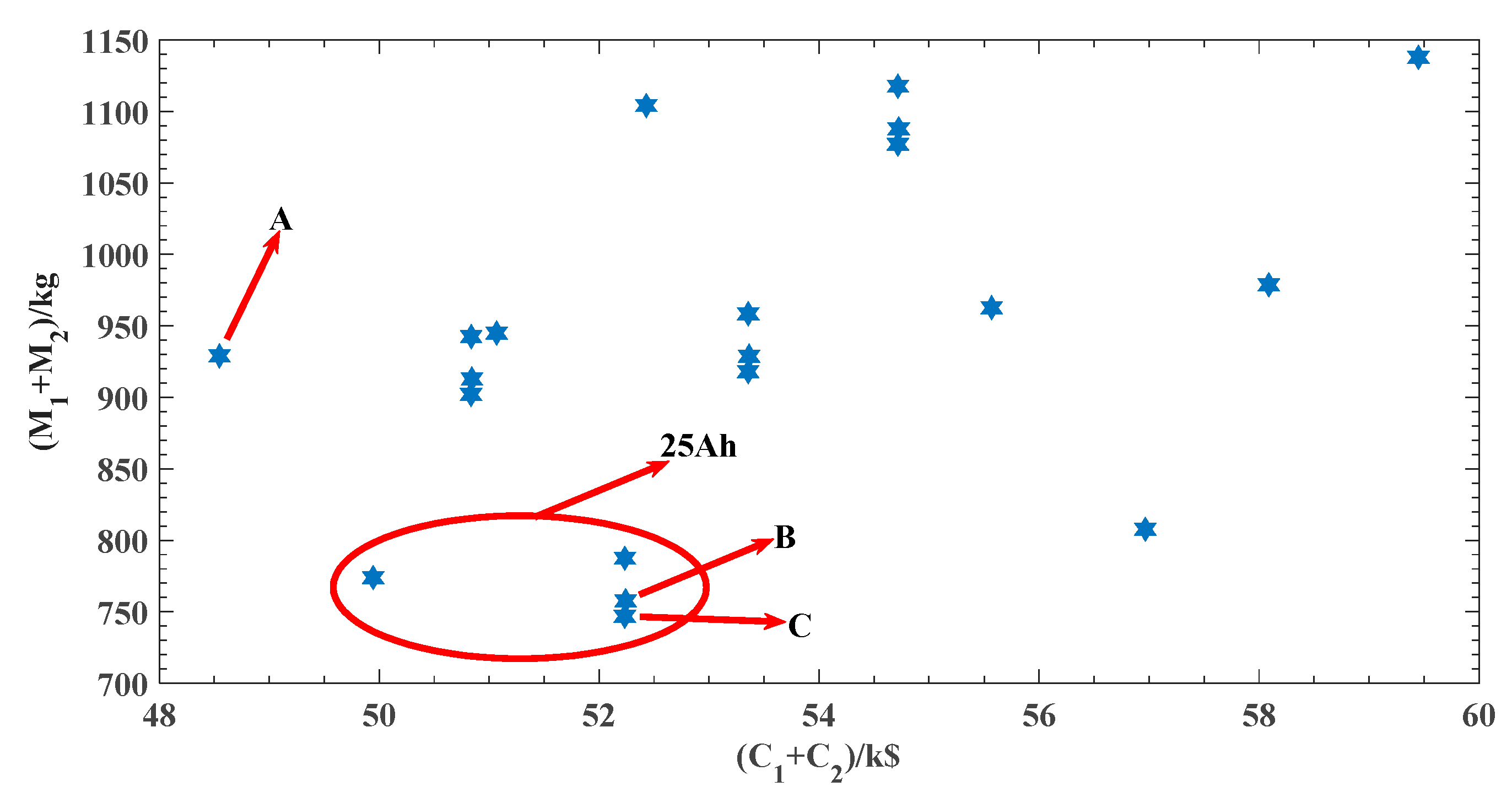
. If
, cost (
,
) and weight (
,
) are optimization targets with equal weights. If the cost is the only optimization objective, point A is the optimization result, with
= 48.547 k
$,
= 929.0 kg,
= 4, and
= 7. The selected battery and supercapacitor have capacities of 60 Ah and 650 F, respectively. If M is the only optimization objective, then point C is the optimization result, with
= 52.231 k
$,
= 747.0 kg,
= 10, and
= 3. The selected battery and supercapacitor have capacities of 25 Ah and 2000 F, respectively. Considering the difference in weight and cost between the supercapacitor and the battery. Supercapacitors have a longer lifespan, so
is greater than
and
is greater than
.
In this paper, point B is the selected result, with
= 52.245 k
$,
= 757.8 kg,
= 10,
= 4, battery capacity
= 25 Ah, and supercapacitor capacity
= 1500 F.
Figure 3 shows the HESS parameter optimization results.


