Article

A Stator Fault Diagnosis Method Based on the Offline Motor Parameter Measurement for PMSM

1
The Fifth Electronics Research Institute of Ministry of Industry and Information Technology, Guangzhou 511370, China
2
Guangdong Provincial Key Laboratory of Electronic Information Products Reliability Technology, Guangzhou 511370, China
*
Author to whom correspondence should be addressed.
World Electr. Veh. J. 2021, 12(4), 248; https://doi.org/10.3390/wevj12040248
Submission received: 25 September 2021 / Revised: 3 November 2021 / Accepted: 17 November 2021 / Published: 20 November 2021

Abstract

:
The permanent magnet synchronous motor (PMSM) is used widely in electric vehicle application due to its high-power density and efficiency. Stator fault is a frequently fault in the motor as it usually works in a harsh environment. Therefore, a stator fault diagnosis method based on the offline motor parameter measurement is proposed to detect and evaluate the stator fault in this paper. Firstly, the line-to-line resistance and inductance of a healthy motor are analyzed when a DC voltage and a high-frequency voltage are excited to the motor respectively, where the DC and AC equivalent circuits at a standstill are introduced. Then, to analyze the resistance and inductance of the stator fault, an extra branch is added to the fault part to obtain the fault equivalent circuits. Accordingly, the stator fault resistance and inductance are derived, and then the resistance and inductance differences between healthy and fault motors are analyzed to provide the basis for the stator fault detection. Furthermore, the fault indicators are defined based on the resistance and inductance differences when a motor has a stator fault. Hence the stator fault severity and location can be evaluated by using these fault indicators. Finally, the experimental results from a 400 W permanent magnet synchronous motor are demonstrated to validate the proposed method.

1. Introduction

The permanent magnet synchronous motor (PMSM) is highly valued as well as widely used in electric vehicles, rail transit, and intelligent manufacturing due to its advantages of high-power density, efficiency, power factor, and small size [1,2]. However, the motors usually work in a harsh environment, leading to their failure. In serious cases, motor fault causes human life losses and material damages. Therefore, it is very important to discover and process early motor faults timely. Stator faults account for almost half of motor faults [3,4]. Reference [5] indicates that stator inter-turn short circuit fault is the primary cause of most stator faults, e.g., phase-to-phase and phase-to-ground faults. Hence, many stator inter-turn short circuit fault diagnosis methods have been developed.
To detect the stator inter-turn short circuit fault at an early stage, the offline and online stator fault diagnosis methods have been investigated [6,7,8,9,10,11,12,13]. The online method is very popular for research as it can monitor motor condition continuously and make failure prognosis in real time [6]. Due to the stator asymmetry of the fault, the negative sequence component will be produced in a motor current. In reference [7,8], the negative sequence in a motor current is adopted to detect the stator inter-turn short circuit fault. However, the inherent asymmetry and voltage unbalance can produce a negative sequence current as well, which will lead to a false alarm. Furthermore, the negative sequence impedance is developed [8,9]. Nevertheless, it is difficult to obtain accurate negative-sequence impedance for an inverter-fed PMSM, because the motor frequency changes with the vehicle speed and contains several harmonics in a motor current. Moreover, the artificial intelligence (AI)-based method is attracting more and more attention in fault diagnosis application. The AI-based method usually classifies the failure types, fault severity and location, where the neural network (NN) [10], modular neural network (MNN) [11], classification and regression tree (CART) [12], k-nearest neighbors (k-NNs) [13], and multilayer perceptron (MLP) [13] are adopted to detect the stator fault. However, the accuracy of the AI-based method heavily depends on training data, which limits its application in practice.
Compared to the online stator fault diagnosis method, the offline method has the advantages of accuracy and being immune to motor running condition. Reference [14] summarizes different offline test methods, including overvoltage (hi-pot), the insulation resistance and polarization index (PI) test, voltage surge (surge comparison), power factor (PF) and PF tip-up, and PD. However, most offline tests need to supply a high voltage to the motor, which may further damage stator insulation.
To detect the stator fault easily and safely, this paper proposes a stator inter-turn short circuit fault diagnosis method by analyzing the line-to-line resistance and inductance, which has advantages of easy implementation and high accuracy. The rest of this paper is organized as follows: Section 2 analyzes the line-to-line resistance and inductance of a healthy motor through the equivalent circuit. In Section 3, an extra branch with Rf is added to the fault part, and thus the fault model is built to obtain the resistance and inductance under fault. Section 4 compares the resistance and inductance of the health and fault motor, and then the fault indicators are introduced to detect and locate the stator fault. In Section 5, the proposed fault diagnosis methods are validated through test results.

2. Line-to-Line Resistance and Inductance Analysis of a Healthy Motor

2.1. Line-to-Line Resistance Analysis

A DC voltage is applied to phases A and B of the motor, the equivalent is displayed in Figure 1, where U and I represent the DC voltage and current, respectively, RA, RB and RC are the stator resistances of phases A, B and C, respectively. For simplicity, it gives the assumption that the motor is symmetrical for a healthy PMSM, i.e., RA = RB = RC = Rs. Hence the line-to-line resistance between any two phases of the motor can be calculated as Equation (1) according to the equivalent circuit.
R A B = R C A = R B C = 2 R s = U I
where RAB, RCA, and RBC are the line-to-line resistances of any two phases of the stator.

2.2. Line-to-Line Inductance Analysis

When a low-magnitude and high-frequency AC voltage is applied to phases A and B, the motor remains stationary, and then the equivalent is displayed in Figure 2. In the figure, ψAB is the flux between A and B, iAB is the current that flows through phases A and B, iA and iB are the current of phases A and B, respectively, and LAA, LBB and LCC are the self-inductances of phases A, B and C, respectively. Here, the AC frequency is high (>400 Hz) to ensure ωL >> R. Hence the stator resistances can be ignored relative to the inductance.
According to the equivalent circuit, the flux of phase A and B can be calculated as
{ ψ A = ( L A A L A B ) i A B ψ B = ( L A B L B B ) i A B
where ψA and ψB are the flux of phase A and B respectively, LAB is the mutual-inductance between phases A and B. Then, the ψAB can be derived as
ψ A B = ψ A ψ B = ( L A A + L B B 2 L A B ) i A B
Hence, the line-to-line inductance L A B e q can be expressed as (4) when the AC voltage is injected to the motor.
L A B e q = ψ A B i A B = L A A + L B B 2 L A B
where L A B e q represents the line-to-line inductance between phase A and B to distinguish the symbol from the mutual inductance L A B . Similarly, when the AC voltage is applied to other phases, the line-to-line inductance is expressed as:
{ L A B e q = L A A + L B B 2 L A B L B C e q = L B B + L C C 2 L B C L C A e q = L C C + L A A 2 L C A
In addition, according to [15], the self- and mutual- inductance can be expressed as:
{ L A A = 2 3 ( L 1 + L 2 cos 2 θ ) ; L A B = 2 3 [ L 1 2 + L 2 cos ( 2 θ 2 3 π ) ] ; L A C = 2 3 [ L 1 2 + L 2 cos ( 2 θ + 2 3 π ) ] ; L B A = 2 3 [ L 1 2 + L 2 cos ( 2 θ 2 3 π ) ] ; L B B = 2 3 [ L 1 + L 2 cos ( 2 θ 4 3 π ) ] ; L B C = 2 3 ( L 1 2 + L 2 cos 2 θ ) ; L C A = 2 3 [ L 1 2 + L 2 cos ( 2 θ + 2 3 π ) ] ; L C B = 2 3 ( L 1 2 + L 2 cos 2 θ ) ; L C C = 2 3 [ L 1 + L 2 cos ( 2 θ + 4 3 π ) ] ;
In which L 1 = ( L d + L q ) / 2 , L 2 = ( L d L q ) / 2 (Ld and Lq are the d-axis and q-axis inductance in the PMSM), and θ is the rotor location angle.
Substituting expressions (6) into (5), line-to-line inductances L A B e q , L B C e q , and L C A e q can be further simplified as:
{ L A B e q = 2 L 1 2 L 2 cos ( 2 θ 2 π 3 ) L B C e q = 2 L 1 2 L 2 cos 2 θ L C A e q = 2 L 1 2 L 2 cos ( 2 θ + 2 π 3 )
It can be seen from (7) that the line-to-line inductance of any two phase is a function of the rotor location angle θ. Thus, the values of the inductance depend on the rotor location at standstill. This phenomenon is not same as the induction motor. In practice, the rotor location is an uncertain parameter at a standstill, leading to the measured line-to-line inductance uncertainty.

3. Line-to-Line Resistance and Inductance Analysis for Stator Fault

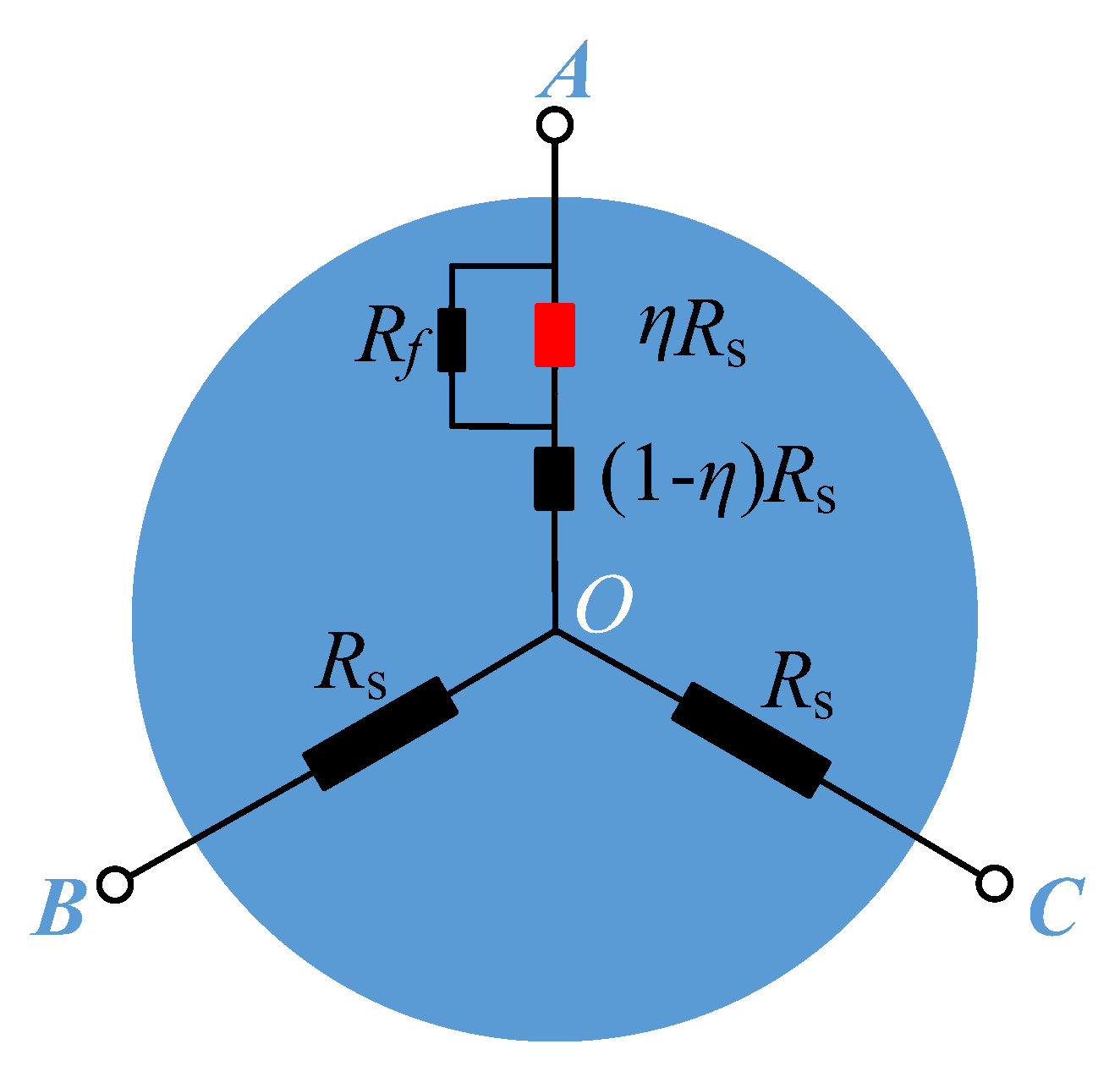
3.1. Line-to-Line Resistance Analysis

When the stator inter-turn short circuit fault occurs in phase A, an extra branch with resistance Rf is added to the fault part of phase A. Accordingly, the DC equivalent circuit of the motor is shown in Figure 3, where Rf represents an additional resistance between the shorted turns, η represents the fault severity and η = ncc/Ns (ncc is the number of the shorted turns and Ns is the total number of stator windings).
According to the equivalent circuit, the stator resistance of three phases can be written as:
R A = R f × η R s R f + η R s + ( 1 η ) R s
R B = R C = R s
Hence, when a DC voltage is supplied to the fault motor, the line-to-line resistance of any two phases is further deduced and simplified as:
{ R A B = R C A = 2 R s η 2 R s 2 R f + η R s R B C = 2 R s
By comparing Equation (10) to (1), it can be seen that RAB and RCA in the stator fault motor are less than those in the healthy motor.

3.2. Line-to-Line Inductance Analysis

The motor equivalent circuit under the high-frequency AC excitation when phase A has a stator inter-turn short fault is shown in Figure 4, where the AC voltage is applied to phase A and B.
According to the circuit, the phases A and B flux can be written as:
{ ψ A = η 2 L A A ( i A B i f ) + ( 1 η ) 2 L A A i A B + η ( 1 η ) L A A ( i A B i f ) + η ( 1 η ) L A A i A B [ η L A B i A B + ( 1 η ) L A B i A B ] ψ B = [ η L A B ( i A B i f ) + ( 1 η ) L A B i A B ] L B B i A B
The above formula can be further simplified as:
{ ψ A = L A A i A B L A B i A B η L A A i f ψ B = L A B i A B L B B i A B η L A B i f
Hence, the line-to-line inductance of the stator fault can be calculated as:
L A B e q = L A A 2 L A B + L B B η ( L A A L A B ) i f i A B
Similarly, when the stator fault occurs in phase A, the line-to-line inductance of any two phases can be derived as:
{ L A B e q = L A A 2 L A B + L B B η ( L A A L A B ) i f i A B L B C e q = L B B + L C C 2 L B C L C A e q = L A A 2 L C A + L C C η ( L A A L C A ) i f i C A
Obviously, when the stator fault occurs in phase A, the phase-A-related inductances L A B e q and L C A e q are not same as the healthy condition. Furthermore, the line-to-line inductance are simplified as:
{ L A B e q = 2 L 1 2 L 2 cos ( 2 θ 2 3 π ) η ( L 1 2 3 3 L 2 sin ( 2 θ π 3 ) ) i f i A B L B C e q = 2 L 1 2 L 2 C o s 2 θ L C A e q = 2 L 1 2 L 2 C o s ( 2 θ + 2 3 π ) η ( L 1 + 2 3 3 L 2 sin ( 2 θ + π 3 ) ) i f i C A
For a permanent magnet synchronous motor, LdLq, and then it can be obtained that ( L 1 2 3 L 2 / 3 ) > 0 . Therefore, when the stator fault occurs, the fault-phase-related inductance decreases compared to the healthy motor.

4. Detection and Evaluation for the Stator Fault

According to the above analysis, when the motor has a stator fault, the line-to-line resistance and inductance of the fault phase decrease. On this basis, the stator fault can be detected by evaluating the resistance and inductance.
Firstly, it can be seen from (10) that the three-phase resistances are unbalance for stator fault, thus the unbalance of the resistance can be adopted as a fault indicator.
FI R = max ( R A B , R B C , R C A ) average ( R A B , R B C , R C A ) average ( R A B , R B C , R C A ) × 100 %
Additionally, when the stator fault occurs, the line-to-line resistance of the fault phase will decrease, which provides a new parameter to evaluate the stator fault severity and location:
FI Δ R = ( R x 0 R x ) R x 0 × 100 %
where the Rx represents the new measured line-to-line resistance, which can be one of RAB, RBC and RCA; Rx0 represents corresponding initial line-to-line resistance.
As the inductances are the function of rotor location, the three-phase inductances are different from each other for an un-known rotor position θ even in a healthy motor; thus the unbalance of the inductances cannot be used as the fault index. On the other hand, it can be seen from (7) that the sum of the inductances is a constant of 6L1, which is independent of the rotor position θ. For a stator fault motor, the sum of the inductances can be derived as:
L A B C e q = 6 L 1 health   part [ η ( L 1 2 3 3 L 2 sin ( 2 θ π 3 ) ) i f i A B + η ( L 1 + 2 3 3 L 2 sin ( 2 θ + π 3 ) ) i f i C A ] fault   part
where L A B C e q is the sum of the measured line-to-line inductances. Therefore, it defines the difference of the inductance L A B C e q before and after the stator fault occurs as the fault feature:
FI Δ L = ( L A B C 0 e q L A B C e q ) L A B C 0 e q × 100 %
in which L A B C 0 e q is the sum of the initial line-to-line inductance.
In summary, when the stator fault occurs, the resistance and inductance will decrease. On this basis, this paper defines three fault indicators—FIR, FI∆R, and FI∆L—and then the stator fault can be further detected and located through the evaluation of the fault indicators.

5. Experiment

5.1. Tested PMSM with the Stator Fault Injection

To obtain a motor with a stator fault, it damages the insulation of some windings, and then takes out some terminals of these windings to the outsides with taps, as shown in Figure 5. Hence, the stator fault can be provided through shorting these additional taps. The nominal parameters of the tested motor are presented in Table 1.
The motor has three coils in a phase, and there are 56 turns in a coil. To obtain different fault severities, it takes out the 1st, 3rd, 6th, 8th, 16th turns of the first coil of phase A to the outside. Accordingly, the number of the shorted turn can be 2, 3, 5, 7, 8, 10, 13, and 15.

5.2. Test Results

It changes the turns that are shorted in the test, and thus the number of the shorted turns changes. Therefore, the line-to-line resistance and inductance under different fault severities can be obtained through the measurements of a LCR meter. Here, the LCR meter can provide the DC and AC voltage to the motor, and then display the measured resistance and inductance values.
The measured line-to-line resistance and inductance under different numbers of shorted turns are shown in Table 2, where the inductance values shown in the table are obtained under the same rotor location. To better observe the resistance and inductance under different fault severities, the resistance and inductance are performed, as the curves shown in Figure 6 and Figure 7, respectively.
We can see that the measured resistances and inductances in Table 2 are different from the rated parameters shown in Table 1. For resistances, this is because the resistance shown in Table 2 is measured under ambient temperature, whereas resistance in Table 1 is obtained under 75 °C. For inductances, according to the above analysis, the line-to-line inductance changes with rotor location, and thus, the inductance value depends on rotor location.
The measured resistances shown in Table 2 are described as the curves shown in Figure 6. It can be seen from the figure that when the stator fault occurs in phase A, both RAB and RCA decrease with the increasing the number of the shorted turns, whereas RBC is almost unchanged. Similarly, as shown in Figure 7, when the number of the shortened turns increases, the line-to-line inductances L A B e q and L C A e q decrease, whereas L B C e q is constant. Comparing Figure 6 and Figure 7, it can be seen that the fault inductances drop sharply relatively to the resistances. This phenomenon reflects that the stator fault has a greater influence on the inductance than resistance, which indicates that inductance is an excellent parameter to recognize the stator fault.
According to Equations (16) and (17), the stator fault indicators FIR and FI∆R can be calculated through the measured data. These two fault indicators under different fault severities are performed, as the curves shown in Figure 8 and Figure 9. In Figure 8, the fault indicator FIR increases with the number of shorted turns from 0.182% to 2.565%. Figure 9 shows that the fault indicators FIRAB and FIRBC increase from 0% to 3.475%, whereas FIRCA is almost unchanged (nearly 0), which indicates that phases B and C are healthy and phase A has a stator fault. Therefore, the fault indicator FIR can determine whether the motor has a stator fault, and the FIRAB, FIRBC, and FIRCA can identify the fault phase.
In addition, the fault indicator of the line-to-line inductance FI∆L can be calculated through Equation (19), and the calculation results are drawn as the curve shown in Figure 10, where FI∆L increases from 0% to 16.4%, which changes significantly compared to the resistance fault indicator FI∆R.
In summary, when the stator fault occurs in phase A, the line-to-line resistances RAB, RCA and the inductances L A B e q , L C A e q increase with the number of the shorted turns, whereas the RBC and L B C e q are almost unchanged, which is in agreement with the proposed algorithm in this paper. Correspondingly, the resistance fault indicators FIR and FI∆R have different degrees of change, which can be adopted to detect the stator fault and locate the fault phase. Compared with the resistance fault indicator, the inductance fault indicator FI∆L increases obviously, which is valuable for stator fault diagnosis.

6. Conclusions

A stator fault detection method based on the line-to-line resistance and inductance analysis is introduced and validated in this paper. The resistance and inductance of healthy and faulty motors are analyzed and compared. On this basis, three fault indicators, FIR, FI∆R and FI∆L, are proposed to detect and locate the stator fault. The test results of a 400 W PMSM under different fault severities lead to the following conclusions:
  • When a stator fault occurs, the line-to-line resistance and inductance related to the fault phase decrease, whereas the others are unchanged.
  • The fault indicator FIR that represents the imbalance of the resistances increases with the number of shorted turns, which can be used to detect the stator fault.
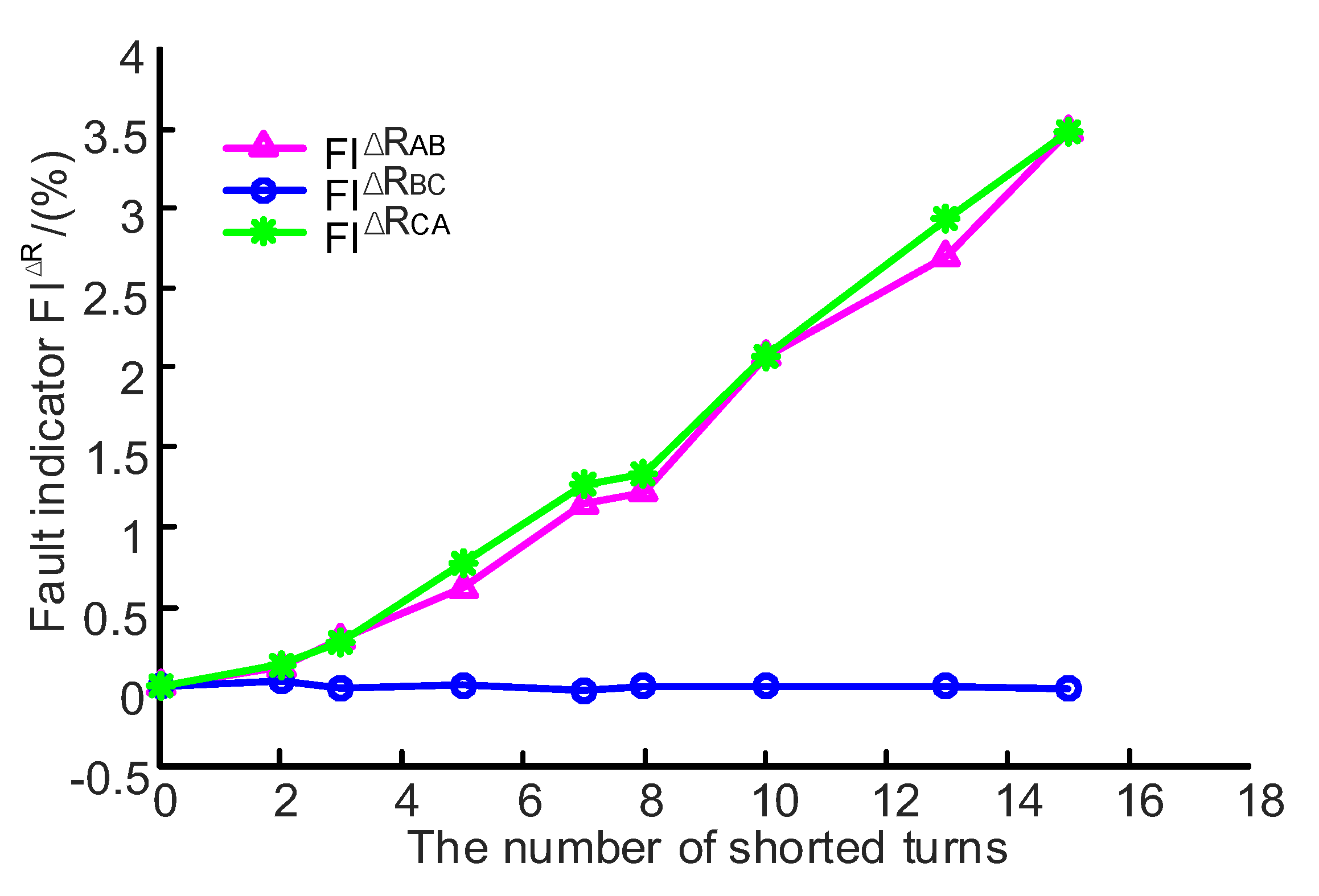
  • The fault indicator FI∆R describes the rate of resistance change. When a stator fault occurs, the FI∆R related to the fault phase increases, whereas the other is nearly 0, which can provide a powerful basis to detect and locate the stator fault.
  • The fault indicator FI∆L increases significantly when the motor has a stator fault, which is valuable for stator fault diagnosis.
In actual implementation, it can measure the resistances and inductances firstly. Then the three fault indicators can be calculated through the above fault indicators definition. Moreover, the stator fault can be estimated by comparing fault indicators FIR, FI∆R, and FI∆L to their thresholds. Here, the stator fault has a great influence on the fault indicator FI∆L, so it can obtain an excellent fault diagnosis result by using the FI∆L. Compared to the online method, the offline method proposed in this paper has the advantage of easily implementation and high accuracy.

Author Contributions

All authors contributed to this work. Conceptualization, J.T. and Y.W.; methodology, J.T. and Y.W.; validation, J.T., C.L., S.L. and J.Z.; writing—original draft, J.T. and Y.W.; writing—review and editing, C.L. All authors have read and agreed to the published version of the manuscript.

Funding

This research was funded by 2019 High-quality Development Special Project of Ministry of Industry and Information Technology (TC19084DZ/2), 2019 Industrial Technology Basic Public Service Platform Project of Ministry of Industry and Information Technology (No. 2019-00896-3-1), and Development Fund Project of China CEPREI Laboratory (19Z13).

Institutional Review Board Statement

Not applicable.

Informed Consent Statement

Not applicable.

Data Availability Statement

Not applicable.

Conflicts of Interest

The authors declare no conflict of interest.

References

  1. Qi, Y.; Bostanci, E.; Zafarani, M.; Akin, B. Severity Estimation of Interturn Short Circuit Fault for PMSM. IEEE Trans. Ind. Electron. 2019, 66, 7260–7269. [Google Scholar] [CrossRef]
  2. Hang, J.; Zhang, J.; Cheng, M.; Huang, J. Online Interturn Fault Diagnosis of Permanent Magnet Synchronous Machine Using Zero-Sequence Components. IEEE Trans. Power Electron. 2015, 30, 6731–6741. [Google Scholar] [CrossRef]
  3. Motor Reliability Working Group. Report of large motor reliability survey of industrial and commercial installations: Part I. IEEE Trans. Ind. Appl. 1985, IA-21, 1985. [Google Scholar] [CrossRef]
  4. Motor Reliability Working Group. Report of large motor reliability survey of industrial and commercial installations: Part II. IEEE Trans. Ind. Appl. 1985, IA-21, 9533. [Google Scholar] [CrossRef]
  5. Ukil, A.; Chen, S.; Andenna, A. Detection of stator short circuit faults in three-phase induction motors using motor current zero crossing instants. Electr. Power Syst. Res. 2011, 81, 1036–1044. [Google Scholar] [CrossRef]
  6. Zheng, D.; Zhang, P. An Online Groundwall and Phase-to-Phase Stator Insulation Monitoring Method for Inverter-Fed Machine. IEEE Trans. Ind. Electron. 2021, 68, 5303–5313. [Google Scholar] [CrossRef]
  7. Liu, T. Research on Stator Winding Interturn Short Circuit Faults Diagnosis of Induction Motor. Ph.D. Thesis, Zhejiang University, Zhejiang, China, 2007. [Google Scholar]
  8. Briz, F.; Degner, M.W.; Zamarron, A. Online Stator Winding Fault Diagnosis in Inverter-Fed AC Machines using High-Frequency Signal Injection. IEEE Trans. Ind. Appl. 2003, 39, 1109–1117. [Google Scholar] [CrossRef]
  9. Cheng, S.; Zhang, P.; Habetler, T.G. An Impedance Identification Approach to Sensitive Detection and Location of Stator Turn-to-Turn Faults in a Closed-Loop Multiple-Motor Drive. IEEE Trans. Ind. Electron. 2011, 58, 1545–1554. [Google Scholar] [CrossRef]
  10. Ghate, V.N.; Dudul, S.V. Cascade Neural-Network-Based Fault Classifier for Three-Phase Induction Motor. IEEE Trans. Ind. Electron. 2011, 58, 1555–1563. [Google Scholar] [CrossRef]
  11. Devi, N.R.; Sarma, D.V.S.S.S.; Rao, P.V.R. Diagnosis and classification of stator winding insulation faults on a three-phase induction motor using wavelet and MNN. IEEE Trans. Dielectr. Electr. Insul. 2016, 23, 2543–2555. [Google Scholar] [CrossRef]
  12. Seera, M.; Lim, C.P.; Ishak, D. Fault Detection and Diagnosis of Induction Motors Using Motor Current Signature Analysis and a Hybrid FMM–CART Model. IEEE Trans. Neural Netw. Learn. Syst. 2012, 23, 97–108. [Google Scholar] [CrossRef] [PubMed]
  13. Maitre, J.; Bouchard, B.; Bouzouane, A. Classification Algorithms Comparison for Interturn Short-Circuit Recognition in Induction Machines Using Best-Fit 3-D-Ellipse Method. Can. J. Electr. Comput. Eng. 2017, 40, 255–265. [Google Scholar] [CrossRef]
  14. Tallam, R.M. A Survey of Methods for Detection of Stator-Related Faults in Induction Machines. IEEE Trans. Ind. Appl. 2007, 43, 920–933. [Google Scholar] [CrossRef]
  15. Krishnan, R. Permanent Magnet Synchronous and Brushless DC Motor Drives; CRC Press, Taylor & Francis Group LLC: Boca Raton, FL, USA, 2010; ISBN 978-0-8247-5384-9. [Google Scholar]
Figure 1. Equivalent circuit when a DC voltage is excited to phase A and B of a healthy motor.
Wevj 12 00248 g001
Figure 2. Equivalent circuit when a high frequency AC voltage is applied to phase A and B of a healthy motor.
Wevj 12 00248 g002
Figure 3. DC equivalent circuit when the motor has stator fault.
Wevj 12 00248 g003
Figure 4. AC equivalent circuit of the stator fault, where the fault occurs in phase A and if is the current that flows through the fault part.
Wevj 12 00248 g004
Figure 5. PMSM with the stator inter-turn short fault injection.
Wevj 12 00248 g005
Figure 6. Line-to-line resistance under different numbers of the shorted turns.
Wevj 12 00248 g006
Figure 7. Line-to-line inductance under different numbers of the shorted turns.
Wevj 12 00248 g007
Figure 8. FIR under different numbers of the shorted turns.
Wevj 12 00248 g008
Figure 9. FI∆R under different numbers of the shorted turns.
Wevj 12 00248 g009
Figure 10. FI∆L under different numbers of shorted turns.
Wevj 12 00248 g010
Table 1. Motor parameters.
ParametersValues
Rated power/(W)400
Rated voltage/(V)220
Rated current/(A)2.8
Rated speed/(rpm)3000
Rated torque/(N.m)1.27
Line-to-line resistance/(Ω)3.43
Line-to-line inductance/(mH)6.6
Inertia/(kg/m2 × 10−4)0.32
Table 2. Measured resistance and inductance.
The Number of Shorted TurnsLine-to-Line Resistance/(Ω)Line-to-Line Inductance/(mH)
RABRBCRCA L A B e q L B C e q L C A e q
health2.83452.84902.84807.45597.37197.3049
2 turns2.83102.84802.84406.54807.34256.6970
3 turns2.82602.84932.84006.06907.32006.4120
5 turns2.81702.84872.82605.70007.30676.1410
7 turns2.80202.84972.81205.52507.29806.0580
8 turns2.80002.84902.81005.43707.29406.0026
10 turns2.77602.84902.78905.38407.29195.9718
13 turns2.75802.84902.76455.31507.28905.9254
15 turns2.73602.84942.74905.29707.28805.9174
Publisher’s Note: MDPI stays neutral with regard to jurisdictional claims in published maps and institutional affiliations.

