1. Introduction
Noise pollution, air pollution, water pollution and solid waste pollution are the four major pollutions in the world today. Noise pollution is a kind of environmental pollution. It has become a major hazard to humans. Working in a noisy environment for a long time will cause a series of physiological and pathological changes in the human nervous system, cardiovascular system, endocrine system and digestive system [
1,
2]. The main sources of motor vibration and noise can be divided into three categories: aerodynamic noise, mechanical noise and electromagnetic noise [
3]. With the improvement in design and manufacturing level and the continuous improvement in processing technology, the noise generated by mechanical vibrations in motors has been effectively mitigated, and the aerodynamic noise in motors is also small. The main source of vibration and noise in motors is electromagnetic vibration noise.
In the EV industry, comfort is an important index to evaluate its performance. The comfort level of the human body refers to the comprehensive influence of various meteorological factors on the physiological functions of the human body, such as heat balance, temperature regulation, the endocrine system and the digestive organs. Continuous, high-intensity vibration and noise will lead to the driver’s sense of pressure and fatigue, which is the manifestation of discomfort. PMSMs are widely used in electric vehicles due to their high efficiency, low temperature rise and high power density [
4,
5,
6]. Therefore, improving the performance of PMSMs has become a significant research direction. In the motor design process, skewed slot stator is usually used to mitigate air gap magnetic density harmonics [
7,
8]. When the slot pitch of the skewed slots is exactly the wavelength of the
th spatial harmonic, the
th harmonic magnetomotive force in the conductor will be offset. Therefore, compared with straight slot motors, the distribution of the air gap flux density and excitation force density in skewed slot motors is different [
9,
10].
Vector control, also known as field-oriented control (FOC), is a technology that uses a frequency converter (VFD) to control a three-phase AC motor and adjusts the output frequency and output voltage of the frequency converter. The amplitude and angle are used to control the output of the motor. Its characteristic is that the magnetic field and torque of the motor can be controlled separately, similar to the characteristics of a separately excited DC motor [
11]. Since the three-phase output current and voltage are expressed as vectors during processing, it is called vector control. When the motor control adopts vector control, a variety of current harmonics of different frequencies will appear in the stator windings of the motor. In the low-frequency band, the order of the current harmonics of the integer slot motor is
; in the high-frequency band, because the vector control strategy usually adopts SVPWM modulation technology, the actual voltage of the inverter is a series of PWM waves with equal amplitudes and unequal duty cycles that are used to be equivalent to sine waves. Fourier decomposition of the PWM waves can obtain high-order harmonic components. These harmonic frequencies are usually distributed in the switching frequency of the inverter and near the multiple frequency [
12,
13,
14,
15]. The frequency of the voltage output by the inverter is as follows:
(
is the switching frequency, and
is the fundamental frequency), when
n = 1, 3, 5, …,
, where
; when
n = 2, 4, 6, …,
, where
These current harmonics will cause exciting force harmonics in the motor, whose frequency is close to the switching frequency [
16,
17,
18].
The skewed slot method can mitigate the harmonic content of the air gap magnetic density in the air gap and mitigate the excitation force density. Considering the actual operation of the motor, due to the on/off of the inverter, an excitation force with a frequency near the switching frequency is introduced. This article examines the sideband current harmonics and vibration in a skewed slot motor to verify whether the skewed slot method can effectively mitigate the vibration caused by the inverter.
2. Modeling and Simulation
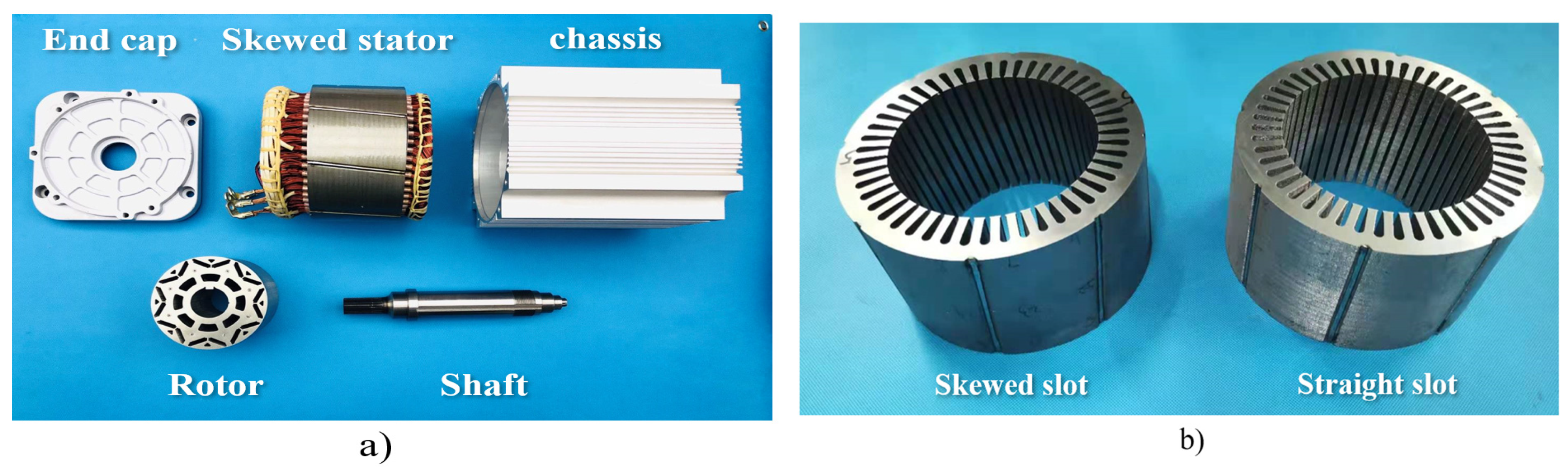
Based on Matlab/Simulink and Ansys software, a co-simulation model of the vector control strategy of a skewed slot motor and a straight slot motor is established. A motor structure diagram of the skewed slot motor is shown in
Figure 1. Some important parameters of the motor are shown in
Table 1. The inclination of the stator winding of the skewed slot motor is 7.5°, and the switching frequency of SVPWM is 10 kHz. Because its multiple frequency exceeds the hearing range, only the sideband harmonics near the switching frequency are analyzed.
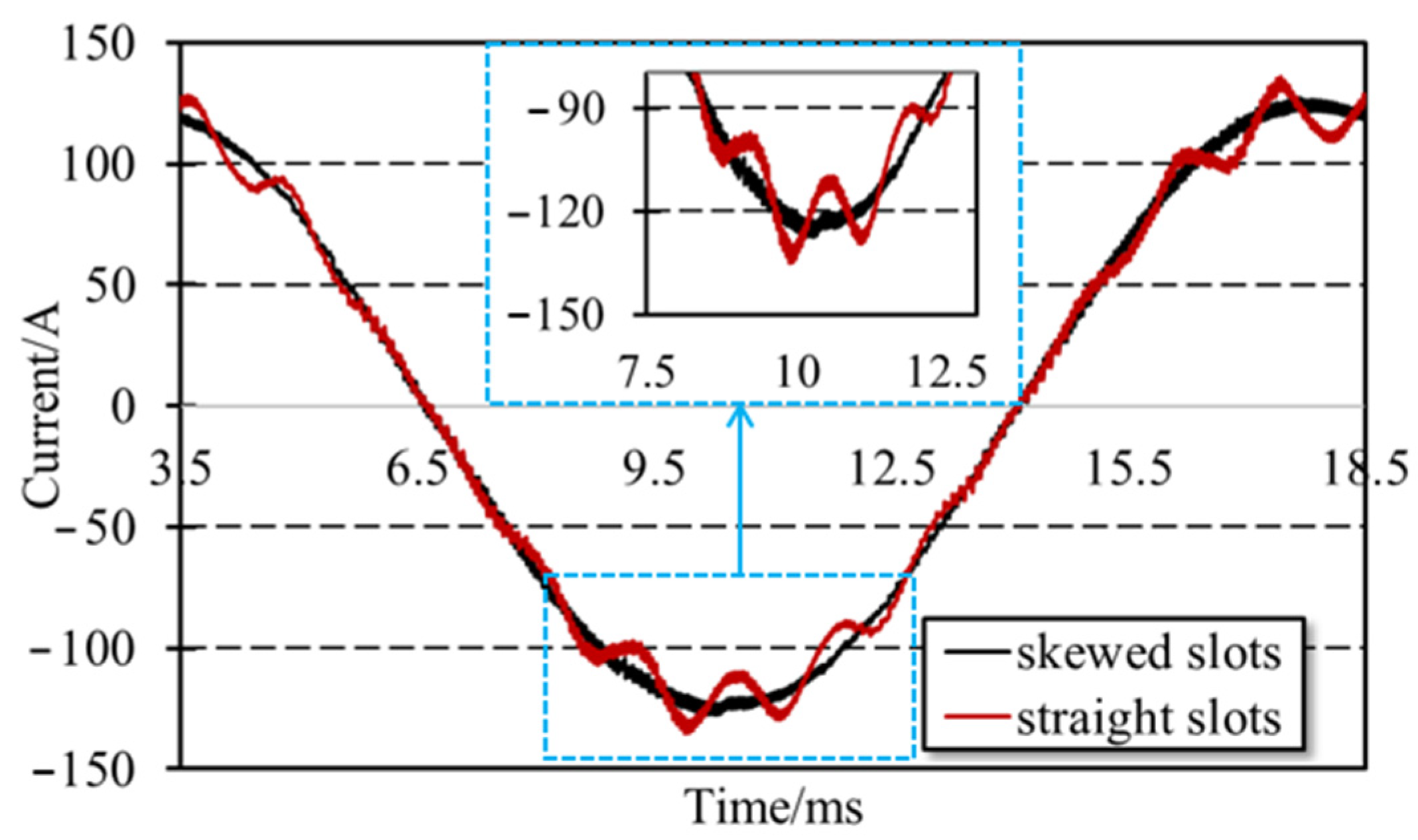
Under a 32 N·m load and 1000 rpm and 3000 rpm speed, the waveforms of the phase A current of the skewed slot motor and the straight slot motor are as shown in
Figure 2 and
Figure 3, respectively. It can be seen that the phase current waveforms of the skewed slot motor at the two speeds have good sinusoidal properties, and the current distortion rate is low. At 3000 rpm, the phase current waveform of the straight slot motor is flat at the peak value, and the current distortion rate is high and does not have good sinusoidal properties. At 1000 rpm, it can be seen from the waveform that the harmonic content of the low-frequency current of the straight slot motor is significantly higher than the harmonic content of the low-frequency current of the skewed slot motor. The use of a skewing slot structure in the stator winding of the motor effectively mitigates the current harmonics, thereby significantly optimizing the performance of the motor.
Fourier decomposition is performed on the currents obtained in the two operating states, and the main current harmonic content at 32 N·m load and 1000 rpm speed is obtained as shown in
Table 2. It can be seen that the 5th and 7th harmonic contents of the skewed slot motor and the straight slot motor are not much different, and the amplitude is small, while the 11th and 13th harmonic current amplitudes of the straight slot motor are 5.81 A and 5.53 A, respectively, much larger than the amplitude of the 11th and 13th harmonic currents of the skewed slot motor. The main current harmonic content at 32 N·m load and 3000 rpm speed is shown in
Table 3. The 5th and 7th harmonic contents of the skewed slot motor and the straight slot motor are not much different, and the amplitude is small, within 1 A. The amplitude of the 11th harmonic current of the straight slot motor is 1.61 A, and the amplitude of the 11th harmonic current of the skewed slot motor is only 0.36 A. The 11th harmonic current of the skewed slot motor is much smaller than that of the straight slot motor. The skewing slot structure has a very obvious effect on the attenuation of tooth harmonics. Compared with straight slot motors, skewed slot motors are not suitable for industrial automation production. For example, the production of a skewed slot motor requires manual wiring, which increases the possibility of winding insulation damage. Therefore, the manufacturing cost of a skewed slot motor is higher than that of a straight slot motor. The advantage of the skewed slot motor is that it can effectively weaken the tooth harmonics of the motor, thereby significantly weakening the cogging torque and improving the running performance of the motor.
The high-frequency current harmonics caused by the frequency converter are analyzed. The Fourier decomposition results of the phase currents obtained under stable operation at a speed of 1000 rpm and a load torque of 32 N·m are shown in
Figure 4a. It can be seen that there is no obvious difference between the sideband current harmonics generated by the inverter for the skewed slot motor and the straight slot motor, and the maximum harmonic amplitude is about 0.4 A. The Fourier decomposition results of the phase current obtained under the stable operation state at a speed of 3000 rpm and a load torque of 32 N·m are shown in
Figure 4b. The sideband current harmonics of the two motors have peaks at the frequencies of
, which is consistent with the theoretical results. Compared with the straight slot motor, the sideband harmonic current of the skewed slot motor has a significantly smaller amplitude. At 3000 rpm, the skewed slot method can effectively mitigate the sideband current harmonics.
By comparing the sideband currents of 1000 rpm and 3000 rpm, it can be seen that the amplitudes of the sideband currents of the two motors are between 1 A and 2 A at 3000 rpm, while the amplitudes of the sideband currents of the two motors are both smaller at 1000 rpm. On the whole, the higher the speed, the greater the amplitude of the sideband current. The sideband current increases as the speed increases.
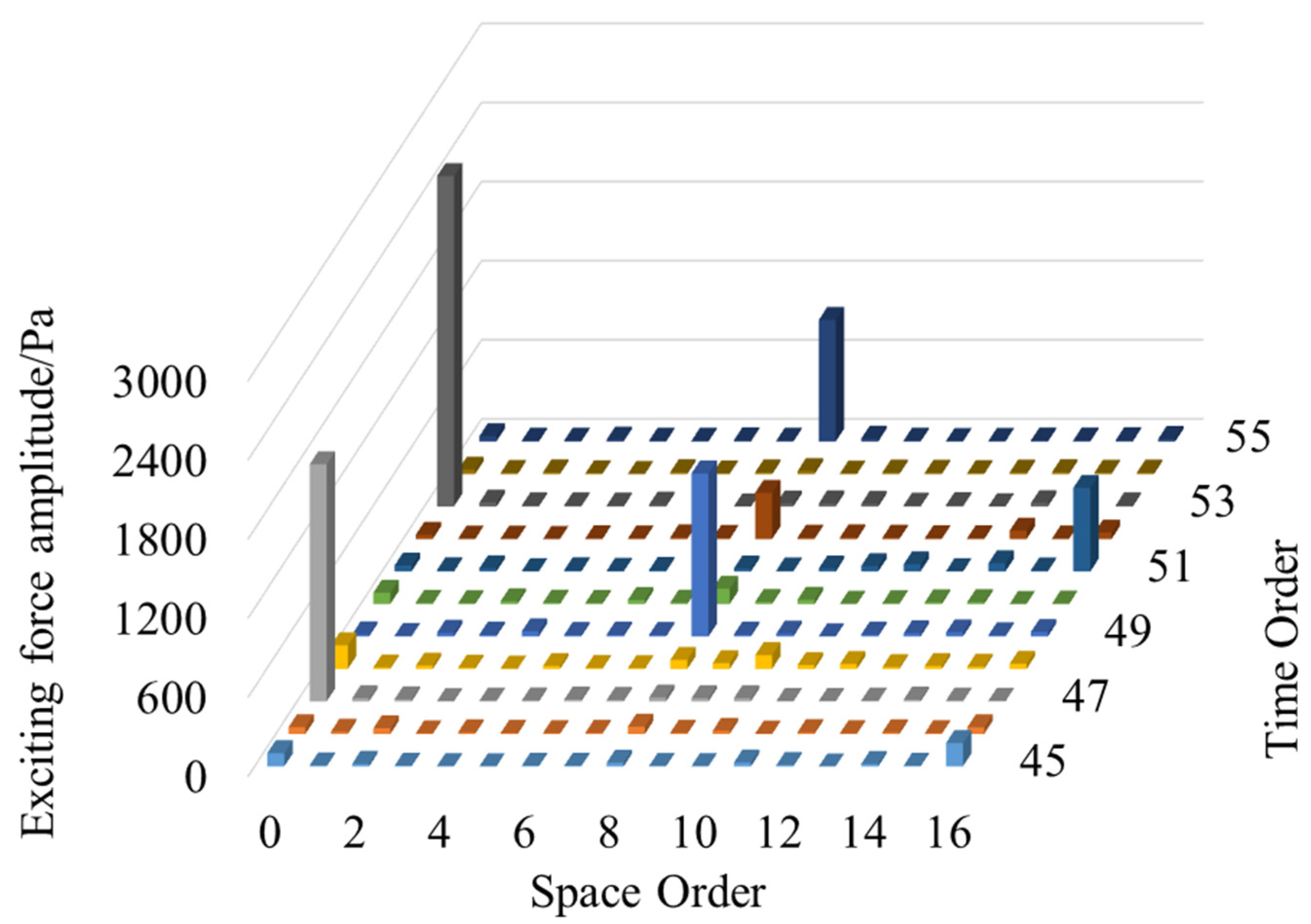
Under the running state of 1000 rpm and 32 N·m, the space and time order distributions of the excitation force of the straight slot motor and the skewed slot motor near the switching frequency are shown in
Figure 5 and
Figure 6, respectively. The value of
is equal to 66.67 Hz, and
.
It can be seen that the harmonic amplitudes of the excitation force of the two motors are larger in the 0th and 8th spatial orders. When the space order is 0 and the time frequency corresponds to , the amplitude of the exciting force density of the two motors is relatively large. When the space order is 8 and the time frequency corresponds to , , the amplitude of the exciting force density of the two motors is relatively large. The harmonic distribution of the excitation force near the switching frequency is not completely consistent with the harmonic distribution of the excitation force caused only by sideband harmonics. This is because the amplitude of the sideband current is not significantly larger than that of other high-frequency harmonic currents when the rotating speed is low.
Under 3000 rpm and 32 N·m operating conditions, the spatial and time order distributions of the excitation force of the straight slot motor and the skewed slot motor near the switching frequency are shown in
Figure 7 and
Figure 8, respectively. The value of
is equal to 200 Hz, and
.
It can be seen that the harmonic amplitudes of the excitation force of the two motors are larger in the 0th and 8th spatial orders. When the space order is 0 and the time frequency corresponds to
, the amplitude of the excitation force of the two motors is larger. When the space order is 8 and the time frequency corresponds to
, the amplitude of the excitation force of the two motors is larger, as shown in
Table 4. In the four different orders of (0, 47), (0, 53), (8, 49) and (8, 55), the exciting force of the skewed slot motor is mitigated to a certain extent compared with that of the straight slot motor.
The spectrograms of the two motors at 1000 rpm and 3000 rpm are shown in
Figure 9a,b. At 1000 rpm, due to the small current harmonics, there is no obvious difference in the excitation force harmonics of the two motors. At 3000 rpm, the exciting force harmonics peak at frequency
. The excitation force distribution of the two motors is similar, and the harmonic amplitude of the skewed slot motor is significantly smaller than that of the straight slot motor.
The order corresponding to the peak value is shown in
Table 5. It can be seen that at the frequencies of 9400 Hz, 9800 Hz, 10,200 Hz, 10,600 Hz and 11,000 Hz, the excitation force harmonics of the skewed slot motor are significantly smaller than those of the straight slot motor, and at the frequencies of 10,200 Hz and 10,600 Hz, the amplitude of the excitation force harmonics of the straight slot motor is compared with that of the skewed slot motor. The amplitude of the excitation force harmonics of the skewed slot motor decreased by more than 10%. It can be considered that the skewed slot method has a certain effect on weakening the sideband excitation force caused by the frequency converter.
3. Experimental Verification and Discussion
In order to analyze the current harmonics of the motor caused by the inverter in the stable operation state, a motor experiment platform is built. The prototype assembly diagram is shown in
Figure 10a. The stator structure is shown in
Figure 10b. The experimental motor has the same structural parameters as the skewed slot motor used in the simulation. The operating conditions are set to 1000 rpm, and the load torque is 32 N·m. In the experiment, a dynamometer is used to apply a load torque, and a current clamp probe detects the current.
The experimental current waveform is shown in
Figure 11a. The three-phase current waveform has a good sinusoidal property. The frequency spectrum obtained by the Fourier decomposition of the phase A current is shown in
Figure 11b. The harmonic distribution of the frequency near the switching frequency obtained by the experiment is consistent with the theory, and the amplitude of the current harmonics appears at the frequency of
.
The experiments are carried out at 1000 rpm, no load and 1000 rpm rated load, respectively. The current waveforms in the two operating states are obtained, and the Fourier decomposition of the currents in the two states is performed to obtain the current spectrum distribution as shown in
Figure 12. It can be seen that the difference in the amplitude of the sideband current caused by the inverter is very small under the no-load and rated load operating conditions. It can be considered that the load has little effect on the sideband current and vibration caused by the inverter.
The rated load was applied, and the skewed slot motor was tested at three different speeds of 500 rpm, 750 rpm and 1000 rpm to obtain the three-phase current waveforms under three working conditions and to perform Fourier decomposition on one of the phase currents and obtain its spectrum distribution as shown in
Figure 13a,b. As shown in the frequency spectrum distribution near the switching frequency of the inverter, it can be seen that near the switching frequency, the current harmonic amplitudes corresponding to different speeds are different. At 1000 rpm, the current has obvious spikes at
, and it is significantly larger than the current amplitude at 500 rpm and 750 rpm. The current amplitude at 750 rpm is obviously larger than the sideband current at 500 rpm. As the speed increases, the amplitude of the sideband current in the skewed slot motor increases significantly. As shown in the frequency spectrum distribution of the low-frequency current, at several different speeds, the amplitude of the current harmonics is not much different, but the frequency of the peaks is different. This is because the fundamental frequency of the current is different at different speeds.
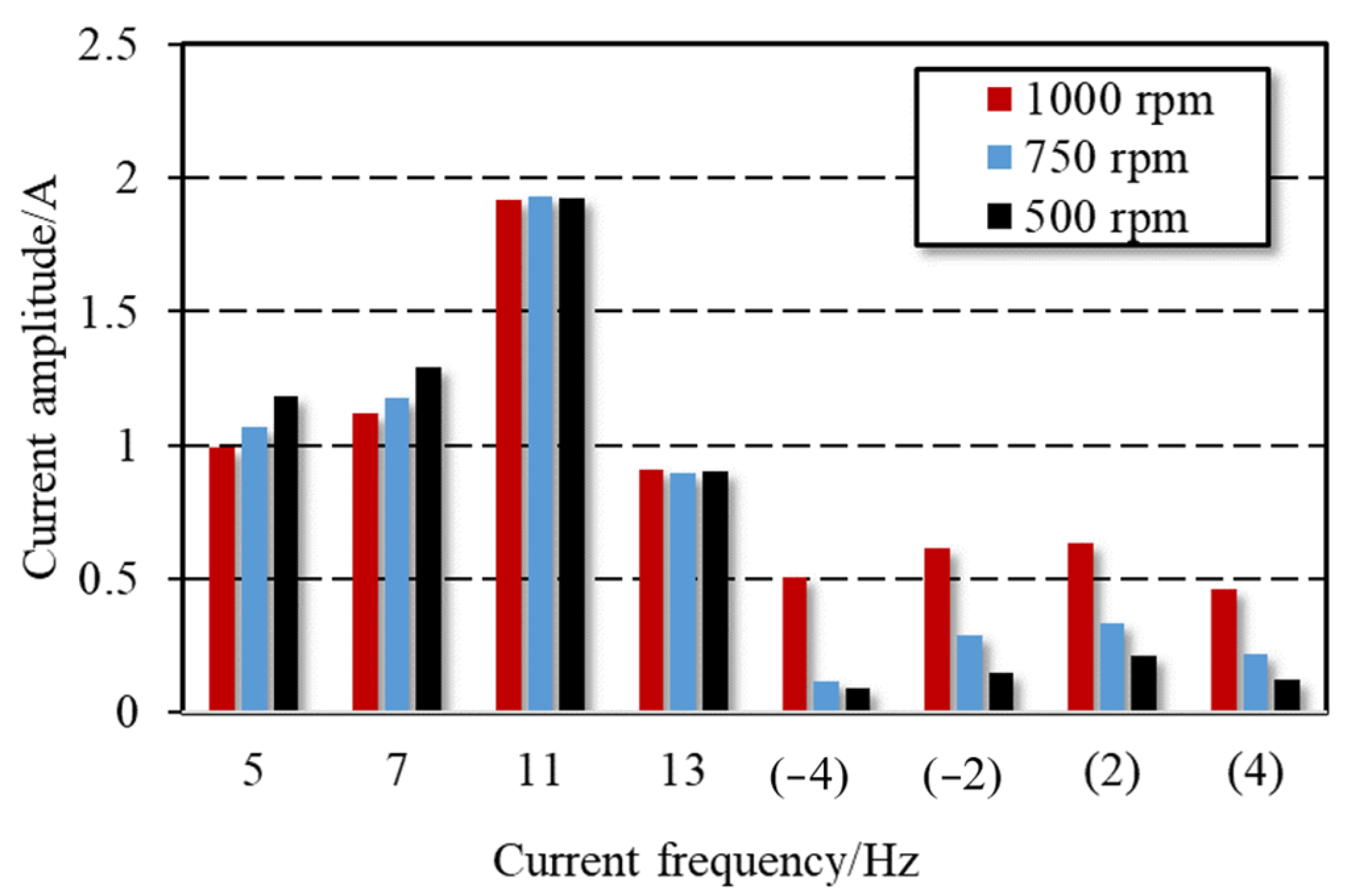
Shown in
Figure 14 are the amplitudes of the current harmonics at several key orders, of which 5, 7, 11 and 13 correspond to the 5th, 7th, 11th and 13th times of the fundamental current, respectively. (−4), (−2), (2) and (4) respectively correspond to the sideband current harmonics of frequency
,
,
and
caused by the frequency converter. When the speed is different, the amplitude of the low-frequency current harmonics is almost the same; the difference is very small. However, the sideband current has a significant increase, and the sideband current may cause the 0-order and 2p-order excitation forces. At high-speed operation, the motor vibration and noise under the vector control strategy increase significantly; if the motor adopts a skewing slot structure, it will have a significantly smaller vibration and less noise than those of the ordinary straight slot structure.
4. Conclusions
Based on the Ansys/Matlab software, this paper conducts a co-simulation and builds an experimental platform to analyze and verify the sideband harmonics of a skewed slot motor. The calculation and Fourier decomposition are mainly aimed at the sideband current harmonics and the excitation force of the skewed slot motor, and a comparison and analysis are carried out with a straight slot motor. The following conclusions can be drawn:
(1) Compared with the straight slot motor, the 11th and 13th harmonics of the skewed slot motor are greatly weakened, which is of great significance for weakening the cogging torque of the motor.
(2) At rated load and no-load operation, the amplitude of the sideband current harmonics is basically the same, and the sideband harmonics caused by the inverter have little relationship with the magnitude of the load.
(3) The sideband harmonics caused by the frequency converter increase with an increase in the motor speed. With an increase in velocity, the increasing trend of the sideband current is much greater than that of the low-frequency current.
(4) The sideband current harmonics of the skewed slot motor are smaller than those of the straight slot motor. This effect is more significant when the speed is higher. Therefore, the skewed slot structure has a certain weakening effect on the excitation force near the switching frequency caused by the sideband current, and as the speed increases, this weakening effect becomes more pronounced.


