Article

Research on the Influence of Collector Microstructure on the Performance of PEM Electrolyzer

1
Clean Energy Automotive Engineering Center, School of Automotive Studies, Tongji University, Shanghai 201800, China
2
Department of Electrical Engineering, Tongji University, Shanghai 201800, China
*
Author to whom correspondence should be addressed.
World Electr. Veh. J. 2021, 12(4), 165; https://doi.org/10.3390/wevj12040165
Submission received: 26 July 2021 / Revised: 15 September 2021 / Accepted: 17 September 2021 / Published: 26 September 2021

Abstract

:
The membrane electrode assembly was prepared by a catalyst coated membrane (CCM) with an effective active area of 10 × 10 cm2 in this work. Porous titanium plates with different diameters were used as anode collectors to study the polarization curve and electrochemical impedance spectroscopy (EIS) of the electrolyzer. The results show that the pore size of a porous titanium plate on the anode side has a significant effect on the performance of the electrolyzer. The best cell performance was obtained when the median diameter of the anode titanium plate was 12.3 um. When the current density is 1 A/cm2, the battery voltage is 2.253 V.

1. Introduction

With the continuous development of the global economy and the improvement of living standards, the demand for energy is also growing [1,2]. At present, about 80% of the energy comes from conventional fossil energy [3]. Carbon emissions and the problem of energy security are becoming increasingly serious. The impact of greenhouse gases, especially carbon dioxide emissions, on the environment gradually exceeds the ability of ecosystems to provide living conditions for human beings. Consequently, it is necessary to realize energy transformation as soon as possible [4]. Compared with traditional fossil energy, renewable energy has less impact on the environment. Hydrogen energy is a renewable and clean energy gradually popularized in recent years, which can replace fossil fuels to a certain extent [5]. Hydrogen has a high calorific value and the gravimetric density of hydrogen energy is generally about seven times higher than the density of fossil fuels [6]. Compared with other fuels, hydrogen theoretically only generates water when burning without releasing toxic substances, so it is also regarded as a future fuel [7,8]. Furthermore, it is efficient and capable of production from diverse domestic resources, both renewable and non-renewable [9,10,11]. Hydrogen can be generated from carbon sources (natural gas and coal), renewable sources (water, biomass, solar, and wind), and nuclear sources. Currently, H2 is mainly produced from non-renewable sources, such as natural gas, via steam reforming (SMR) [12]. Hydrogen of corresponding purity is obtained by reaction, separation and purification. The traditional way of hydrogen production still relies on fossil energy. Among various hydrogen production methods, electrolytic water can produce hydrogen with high density and environmental protection. In addition, the electrolytic cell has the advantage of relatively compact volume [13,14,15,16].
Proton exchange membrane electrolyzer cell (PEMEC) consists of membrane electrode assembly (MEA), collector, bipolar plate with flow channel and end plate. The collector is a porous medium placed between the MEA on both sides of the electrode and the bipolar plate, which mainly plays the role of conduction and mass transfer [17]. Under the action of external voltage, water loses electrons at the anode and generates oxygen and hydrogen ions. Hydrogen ions pass through the proton exchange membrane and reach the cathode, where electrons are generated and hydrogen is precipitated. High purity oxygen can be obtained by this method [18]. Reducing the electrolytic voltage and optimizing the performance of the electrolyzer are among the hot issues in the research of electrolyzers. At low current density, the polarization of the electrolyzer is mainly affected by reaction kinetics, while at medium current density, it is mainly ohmic polarization, which comes from the internal resistance and contact resistance of electrolyzer components. When the current density is high, the effect of mass transfer on the performance of the electrolyzer increases gradually. With the development of research, the mass transfer in the electrolyzer has been given more and more attention. The mass transfer in the electrolyzer mainly includes the mass transfer from water to anode, the diffusion of escaping gas and the electroosmotic transport on the proton exchange membrane, in which the mass transfer of water and gas is the main source of mass transfer loss [19,20,21]. The water in the catalytic layer decomposes to generate hydrogen, which is transmitted to the channel through gas diffusion layer (GDL). On the one hand, the liquid water flows through the gas diffusion layer along the direction of the channel, on the other hand, it penetrates into the catalytic layer through capillary action. The electrons generated by water decomposition are transmitted to the external circuit throughGDL and BP (bipolar plate). Gas accumulation and insufficient water supply will affect the performance of the electrolyzer [22,23,24,25]. The collector plays an important role in charge transfer and water gas mass transfer, so it is necessary to determine the micro size of the collector [26]. At present, the research on the micro size of the collector is mostly based on the small size of the active area, while the research on the collector for large area MEA is less.
In this paper, titanium plates with different apertures were used as anode collectors and MEA with an effective working area of 10 × 10 cm2. The effect of microstructure of porous titanium plates on the performance of electrolytic cells was studied. The physical parameters of collectors were characterized, and the polarization curves of collectors with different apertures were measured, in order to obtain the optimal process parameters of anode collectors with this size.

2. Materials and Methods

2.1. Preparation

In this paper, the membrane electrode assembly was prepared by nafion-117 membrane. Cutting film area 11 × 11 cm2, catalyst spraying area 10 × 10 cm2. Before it used for spraying, the membrane was pretreated with 3% H2O2 (wt%) and 5% H2SO4 (wt%) at 90 °C for 1 h sequentially. Then, it was pretreated with high purity water at 90 °C for 1 h. Finally, the membrane was washed by deionized water and dried at 80 °C for spraying.
In this paper, 60% Pt/C was used as a cathode catalyst, the loading of Pt was 0.4 mg/cm2, IrO2 was used as anode catalyst, and the loading of IrO2 was 1.5 mg/cm2. After the catalyst, deionized water, isopropanol and Nafion solution were mixed in a certain proportion (The Nafion mass of anode is 5% of the catalyst and that of cathode is 30%), the spray slurry was prepared by ultrasonic dispersion.
The structure of the PEM electrolyzer used in this paper is shown in Figure 1. The porous titanium plate is fixed with a silica gel pad, and then the MEA is pasted on the silica gel pad with a polyimide film. Titanium plates are used as collectors.

2.2. Experimental Process

The pressure of 1.6 MPa is applied to the assembled electrolyzer by air cylinder, 80 °C deionized water is supplied to the electrolyzer by advection pump, the water temperature is guaranteed by constant temperature water bath, and the flow rate is 50 mL/min. The cathode collector uses porous titanium plate with filtration grade T3, and the anode collector uses porous titanium plate with filtration grade T4, T3, T2 and T1, respectively.
The polarization curve of the cell was measured at the current density of 0.01–1 A/cm2. In order to get more accurate data, it is necessary to make the cell work at 10–100 A current for a period of time before measuring the polarization curve. The electrochemical impedance of MEA was measured by electrochemical workstation. The bias voltage is 1.5 V, the perturbation voltage is 0.06 V, and the frequency range is 0.1 Hz–100,000 Hz. The morphology of the anodic porous titanium plate was observed by optical microscope, and the pore size distribution and other physical parameters were characterized by mercury porosimetry.

3. Results

3.1. Characterization of Titanium Plate

The porous titanium plate was characterized by mercury intrusion porosimetry (MIP). Mercury is not wettable to general solids, so external pressure is needed to make it enter the hole. The larger the external pressure is, the smaller the radius of the hole into which mercury can enter. Therefore, the pore size distribution can be obtained by measuring the amount of Mercury entering the hole under different external pressures. The pore size distribution of the porous titanium plate is shown in Figure 2, and other properties are given in Table 1.
The morphology of titanium plates is shown in Figure 3 a(T1), b(T2), c(T3) and (d)(T4). The dark area indicates the pores formed by sintering. It can be seen that with the increase of filtration grade, the size of sintered particles decreases and the pore size also decreases. The average sizes of particles were 593 um(T1), 397 um(T2), 217 um(T3) and 113 um(T4), respectively. There is no obvious concentrated distribution of pore size in T1 titanium plate in accordance with Figure 2. While the pore size of T2 is mainly distributed in about 40–100 um and that of T3 is mainly 20–45 um. The pore size distribution of T1 is the most concentrated, about 10–22 um. This is because the average size of the sintered particles is small and the packing is more compact, so the pore size is small and the distribution is relatively concentrated. It can be seen from the table that T3 has the largest porosity of 62.9%, and T1 has the smallest porosity of 28.8%. The porosity, affecting the penetration of liquid and the escape of gas, is generally related to the arrangement, size and surface shape of particles. That of porous titanium plate usually obtained by sintering is 20–70%, which is related to the sintering process of titanium plate.

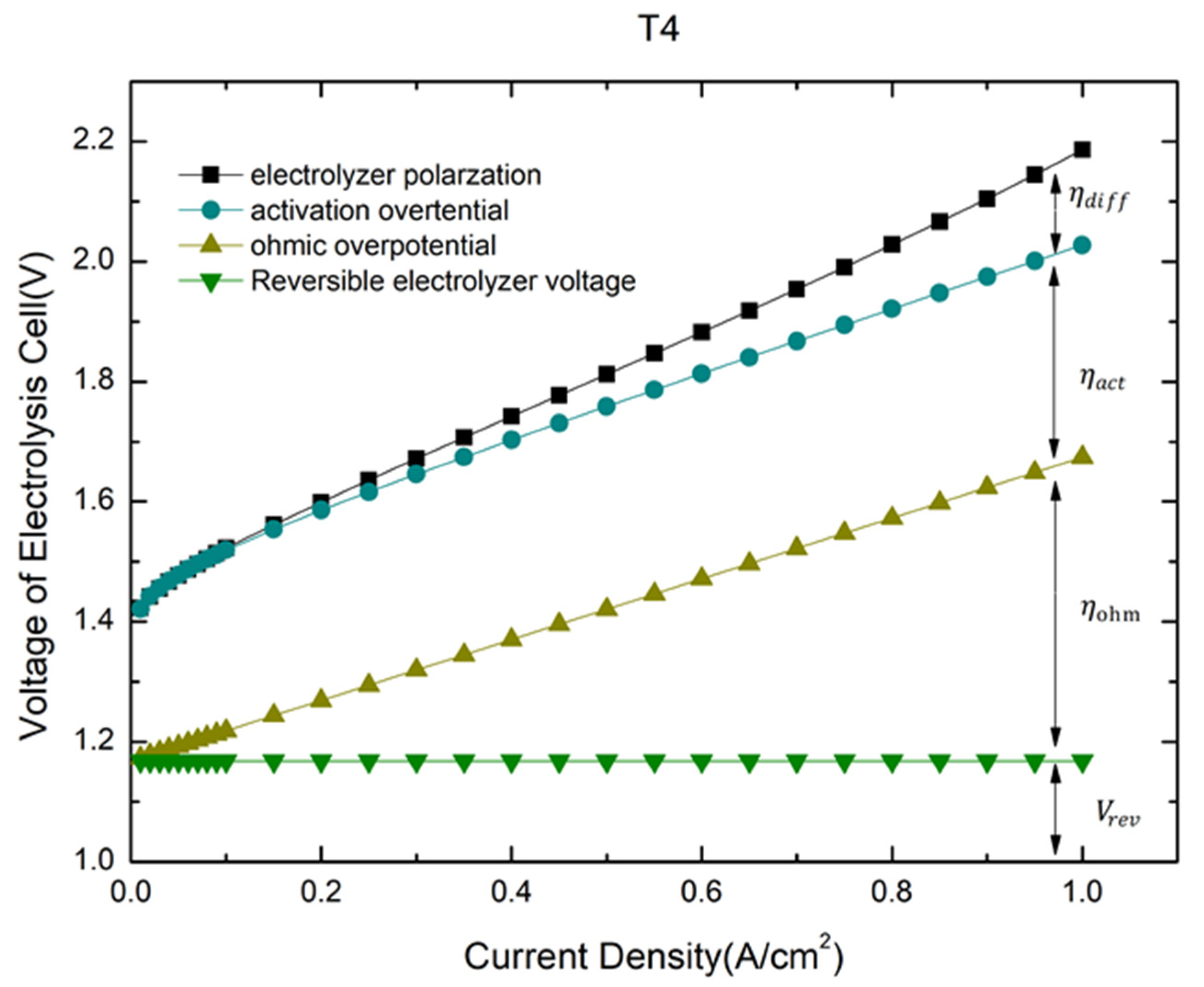
3.2. Electrolytic Cell Performance

Electrochemical impedance spectroscopy analyzes the electrochemical behavior by measuring the change of impedance with sine wave frequency, which is a common method in electrochemical research. The applied voltage is 1.5 V and the disturbance voltage is 60 mV. The impedance and equivalent circuit of the electrolytic cell are shown in Figure 4. Rs represents the ohmic impedance of the whole electrolytic cell, Rct1 and Rct2 represent the charge transfer impedance of the anode and cathode, respectively. CPE is a constant phase element, which replaces capacitance in EIS test. Two parallel RC units are used to simulate the activation kinetics of anode and cathode, and ohmic resistance is used to describe ohmic impedance [27]. The two semicircles represent the charge transfer impedance of the cathode and anode, respectively. The ohmic impedance and charge transfer impedance of the electrolytic cell can be clearly seen from the fitting curve, which are shown in Table 2. The ohmic impedances are 0.656   Ω · cm 2 (T1), 0.604   Ω · cm 2 (T2), 0.546   Ω · cm 2 (T3) and 0.506   Ω · cm 2 (T4), respectively. The difference of ohmic impedance is obvious, which is mainly composed of bipolar plate resistance MEA internal resistance GDL internal resistance and contact impedance. The conductivity can also directly show the function of titanium plate. For this experiment, bipolar plate and membrane electrode of electrolytic cell are the same sample, so the difference of ohmic impedance is mainly caused by collector internal resistance. The results show that the contact area between the porous titanium plate with smaller average aperture and MEA is larger, so the contact resistance is smaller. Due to the smaller particle size and the denser inner part, T4 has higher conductivity, so the ohmic impedance of T4 is the smallest. The charge transfer impedance, which reflects the activation impedance of cathode and anode, is 0.112 Ω·cm2 (T1), 0.093 Ω·cm2 (T2), 0.121 Ω·cm2 (T3) and 0.099 Ω·cm2 (T4), respectively. The microstructure of the collector will affect the contact condition between the collector and MEA, and then the charge transfer resistance. The aperture of the collector determines the size of the bubble leaving the collector. Larger bubbles will increase the gas coverage of the contact surface. Higher gas phase volume fraction is conducive to reactant [28,29]. Similarly, too large porosity will also reduce the effective reaction area. Proper pore diameter and porosity can promote the effective transport of protons and make protons leave MEA efficiently [30]. Considering the effects of pore size and porosity, T2 shows the minimum charge transfer impedance [31].
Porous titanium plates with different apertures were used as anode collectors, and the polarization curves of the electrolyzer were measured, as shown in Figure 5. The results show that when the current density is 0–0.07 A/cm2, the cell operates in the active polarization region. When the current density is 0.07 A/cm2, the cell voltage is 1.551 V(T1), 1.492 V(T2), 1.498 V(T3), and 1.496 V(T4), respectively. When the current density is 0.07–1 A/cm2, the cell works in the ohmic polarization region, and the polarization voltage increases linearly. When the current density reaches 1 A/cm2, the electrolytic voltage of the cell is 2.532 V(T1), 2.253 V(T2), 2.242(T3), 2.186 V(T4), respectively. The results show that in the activated polarization region, under the condition of small current, the polarization voltage of electrolyzer with different anode collectors has little difference. As in the range of current density, the main factors affecting the performance of the electrolyzer are catalyst and electrode materials, and the difference of overpotential is mainly caused by ohmic polarization. Under the condition of high current, the effect of mass transfer increases. Therefore, the overpotential difference of the electrolyzer is mainly caused by mass transfer and ohmic impedance.
The cell voltage consists of reversible voltage and polarization overpotential:
V C e l l = V r e v + η = V r e v + η a c t + η o h m + η d i f f
η a c t , η o h m , η d i f f denotes activation polarization, ohmic polarization and diffusion polarization, respectively. Diffusion polarization is related to material transport in the electrolyzer, such as gas–liquid two-phase flow in channel and diffusion in diffusion layer. Ohmic polarization is related to ohmic impedance and current of cell, which is in accordance with Ohm law. The activation polarization part can be described by Tafel formula:
η a c t = R T α n F I n   j 0 + R T α n F I n   j
η a c t = a + b l o g   j
When the working temperature of the electrolyzer is 80 °C, the reversible voltage is Vrev = 1.168 V. The total polarization voltage of electrolytic cell with T4 can be divided into the reversible part and irreversible part, as shown in Figure 6. When the current density is 1 A/cm 2, the ohmic polarization is 0.506 V, the activation polarization is 0.353 V, and the mass transfer polarization is 0.159 V. They account for 23.15%, 16.16% and 7.26% of the total polarization voltage, respectively. They account for 23.15%, 16.16% and 7.26% of the total polarization voltage, respectively. Among them, ohmic polarization and activated polarization account for most of the irreversible loss. It can be seen from the figure that the mass transfer loss increases with the increase of current density. Therefore, the optimization of mass transfer is of great help to improve the performance of the electrolyzer at high current density.
The polarization loss of the electrolyzer at 1 A/cm2 is shown in Table 3, in which the ohmic loss are 0.656 V (T1), 0.604 V(T2), 0.546 V(T3) and 0.506 V(T4), respectively. In this paper, DC power supply is used. Therefore, the ohmic loss is mainly determined by the ohmic impedance of the electrolytic cell. The activation loss was 0.453 V(T1), 0.352 V(T2), 0.348 V(T3) and 0.353 V(T4), respectively. There was no significant difference in the activation loss between T4, T3 and T2. This is because the activation polarization part is mainly determined by the reaction kinetics, and the catalyst is the most important factor. The increase of the activation polarization of T1 may be due to the larger pore size, which leads to higher water immersion and difficult gas diffusion and overflow, resulting in local accumulation and increasing the mass transfer resistance of water to the surface of catalytic layer. The local accumulation of products affects the forward reaction, so the activation polarization increases. The diffusion polarization was 0.246 V(T1), 0.129 V(T2), 0.180 V(T3) and 0.159 V(T4), respectively. The diffusion polarization has no obvious rule with the pore size, because the mass transfer in the gas diffusion layer includes two parts: liquid water diffusion from the flow field to the membrane electrode and gas diffusion to the flow field. Large pore size has little resistance to mass transfer, but due to the opposite diffusion direction of gas–liquid two-phase, excessive water content in pores will hinder the outward diffusion of gas, and the accumulation of gas will also affect the mass transfer of water. Although small pore size has great resistance to mass transfer, due to smaller particle size, denser structure and more complex internal structure, more diverse gas–liquid two-phase diffusion path, less prone to local water accumulation and gas accumulation, it is beneficial to mass transfer. In this paper, the best collector aperture condition for diffusion polarization is 12.3 um. Combined with the performance of electrolytic cell, the porosity of more than 60% and 12.3 um were taken as the parameters of porous titanium plate for further study.

4. Conclusions

When the current density is 0.07 A/cm2, the corresponding cell voltages of T1–T4 are 1.551 V, 1.492 V, 1.498 V, respectively. When the current density reaches 1 A/cm2, the electrolytic voltage of the cell is 2.186 V, 2.242 V, 2.253 V and 2.532 V, respectively. In general, it can be considered that with the decrease of the aperture of the anode collector, the polarization voltage of the cell decreases and the performance of the cell improves under the same current density. Reducing the aperture of the anode collector will reduce the ohmic impedance of the electrolyzer, and the microstructure of the collector will also affect the charge transfer impedance. Mass transfer polarization is mainly related to the microstructure of porous titanium plate. Porosity and pore size all affect the mass transfer effect.
To sum up, under the current density of 1 A/cm 2, the T4 titanium plate has the smallest ohmic impedance and better mass transfer performance, so it shows the best electrolytic performance under this condition, that is, the polarization voltage is 2.186 V, in which the ohmic polarization is 0.506 V, the activation polarization is 0.353 V, and the mass transfer polarization is 0.159 V.
In this paper, the effect of collector microstructure on the performance of electrolytic cells is studied. The optimum collector parameters of large active area electrolytic cells are preliminarily determined, that is, median pore diameter is 50 um and the porosity is 0.5. The results can provide some reference for further research and optimization of collector parameters.

Author Contributions

Conceptualization, S.W. and W.J.; methodology, H.L. and W.J.; software, S.W.; validation, H.L., X.S. and C.Z.; formal analysis, Y.S.; investigation, W.J.; resources, W.J.; data curation, W.J.; writing—original draft preparation, W.J.; writing—review and editing, S.W. and H.L.; visualization, S.W. and Y.S.; supervision, C.Z.; project administration, H.L.; funding acquisition, H.L. All authors have read and agreed to the published version of the manuscript.

Funding

This work was supported by the National Key R&D Program of China (No. 2018YFB1503100).

Acknowledgments

Thanks to the organizers of the 34th World Electric Vehicle Congress for their commendable work. We would like to thank the editors and reviewers for their valuable comments.

Conflicts of Interest

The authors declare no conflict of interest or personal relationships that could have appeared to influence the work reported in this paper.

References

  1. Dawood, F.; Anda, M.; Shafiullah, G. Hydrogen production for energy: An overview. Int. J. Hydrog. Energy 2020, 45, 3847–3869. [Google Scholar] [CrossRef]
  2. Alanne, K.; Cao, S. An overview of the concept and technology of ubiquitous energy. Appl. Energy 2019, 238, 284–302. [Google Scholar] [CrossRef]
  3. Nemitallah, M.; Imteyaz, B.; Abdelhafez, A.; Habib, M.A. Experimental and computational study on stability characteristics of hydrogen-enriched oxy-methane premixed flames. Appl. Energy 2019, 250, 433–443. [Google Scholar] [CrossRef]
  4. Ripple, W.; Wolf, C.; Newsome, T.; Galetti, M.; Alamgir, M.; Crist, E.; Ibrahim-Mahmoud, M.; Laurance, W. World scientists’ warning to humanity: A second notice. Bioscience 2017, 67, 1026–1028. [Google Scholar] [CrossRef]
  5. Tarhan, C.; Çil, M.A. A study on hydrogen, the clean energy of the future: Hydrogen storage methods. J. Energy Storage 2021, 40, 102676. [Google Scholar] [CrossRef]
  6. Yang, J.; Sudik, A.; Wolverton, C.; Siegel, D. High capacity hydrogen storage materials: Attributes for automotive applications and techniques for materials discovery. Chem. Soc. Rev. 2010, 39, 656–675. [Google Scholar] [CrossRef] [PubMed] [Green Version]
  7. Okolie, J.A.; Patra, B.R.; Mukherjee, A.; Nanda, S.; Dalai, A.K.; Kozinski, J.A. Futuristic applications of hydrogen in energy, biorefining, aerospace, pharmaceuticals and metallurgy. Int. J. Hydrog. Energy 2021, 46, 8885–8905. [Google Scholar] [CrossRef]
  8. Nath, K.; Das, D. Modeling and optimization of fermentative hydrogen production. Bioresour. Technol. 2011, 102, 8569–8581. [Google Scholar] [CrossRef]
  9. Pethaiah, S.S.; Sadasivuni, K.K.; Jayakumar, A.; Ponnamma, D.; Tiwary, C.S.; Sasikumar, G. Methanol Electrolysis for Hydrogen Production Using Polymer Electrolyte Membrane: A Mini-Review. Energies 2020, 13, 5879. [Google Scholar] [CrossRef]
  10. Bhawna; Sharma, S. Metal based catalysts for hydrogen production reactions. Mater. Today Proc. 2021, 2–6. [Google Scholar] [CrossRef]
  11. Ayers, K. High efficiency PEM water electrolysis: Enabled by advanced catalysts, membranes, and processes. Curr. Opin. Chem. Eng. 2021, 33, 100719. [Google Scholar] [CrossRef]
  12. Qyyum, M.A.; Dickson, R.; Shah, S.F.A.; Niaz, H.; Khan, A.; Liu, J.J.; Lee, M. Availability, versatility, and viability of feedstocks for hydrogen production: Product space perspective. Renew. Sustain. Energy Rev. 2021, 145, 110843. [Google Scholar] [CrossRef]
  13. Kirk, D.W.; Thorpe, S.J.; Suzuki, H. Ni-base amorphous alloys as electrocatalysts for alkaline water electrolysis. Int. J. Hydrog. Energy 1997, 22, 493–500. [Google Scholar] [CrossRef]
  14. Holladay, J.D.; Hu, J.; King, D.L.; Wang, Y. An overview of hydrogen production technologies. Catal. Today 2009, 139, 244–260. [Google Scholar] [CrossRef]
  15. Grigoriev, S.; Porembsky, V.; Fateev, V. Pure hydrogen production by PEM electrolysis for hydrogen energy. Int. J. Hydrog. Energy 2006, 31, 171–175. [Google Scholar] [CrossRef]
  16. Anwar, S.; Khan, F.; Zhang, Y.; Djire, A. Recent development in electrocatalysts for hydrogen production through water electrolysis. Int. J. Hydrog. Energy 2021, 46, 32284–32317. [Google Scholar] [CrossRef]
  17. Ito, H.; Maeda, T.; Nakano, A.; Hwang, C.M.; Ishida, M.; Kato, A.; Yoshida, T. Experimental study on porous current collectors of PEM electrolyzers. Int. J. Hydrog. Energy 2012, 37, 7418–7428. [Google Scholar] [CrossRef] [Green Version]
  18. Ma, Z.; Witteman, L.; Wrubel, J.A.; Bender, G. A comprehensive modeling method for proton exchange membrane electrolyzer development. Int. J. Hydrog. Energy 2021, 46, 17627–17643. [Google Scholar] [CrossRef]
  19. Rahim, A.H.A.; Tijani, A.S.; Kamarudin, S.; Hanapi, S. An overview of polymer electrolyte membrane electrolyzer for hydrogen production: Modeling and mass transport. J. Power Sources 2016, 309, 56–65. [Google Scholar] [CrossRef]
  20. Lafmejani, S.S.; Olesen, A.C.; Kær, S.K. VOF modelling of gas–liquid flow in PEM water electrolysis cell micro-channels. Int. J. Hydrog. Energy 2017, 42, 16333–16344. [Google Scholar] [CrossRef] [Green Version]
  21. Fritz, D.L.; Mergel, J.; Stolten, D. PEM Electrolysis Simulation and Validation. ECS Trans. 2014, 58, 1–9. [Google Scholar] [CrossRef]
  22. Chen, Q.; Wang, Y.; Yang, F.; Xu, H. Two-dimensional multi-physics modeling of porous transport layer in polymer electrolyte membrane electrolyzer for water splitting. Int. J. Hydrog. Energy 2020, 45, 32984–32994. [Google Scholar] [CrossRef]
  23. Dedigama, I.; Angeli, P.; Ayers, K.; Robinson, J.; Shearing, P.; Tsaoulidis, D.; Brett, D. In situ diagnostic techniques for characterisation of polymer electrolyte membrane water electrolysers-Flow visualisation and electrochemical impedance spectroscopy. Int. J. Hydrog. Energy 2014, 39, 4468–4482. [Google Scholar] [CrossRef]
  24. Kúš, P.; Ostroverkh, A.; Khalakhan, I.; Fiala, R.; Kosto, Y.; Šmíd, B.; Lobko, Y.; Yakovlev, Y.; Novakova, J.; Matolínová, I.; et al. Magnetron sputtered thin-film vertically segmented Pt-Ir catalyst supported on TiC for anode side of proton exchange membrane unitized regenerative fuel cells. Int. J. Hydrog. Energy 2019, 44, 16087–16098. [Google Scholar] [CrossRef]
  25. Wu, H.-W. A review of recent development: Transport and performance modeling of PEM fuel cells. Appl. Energy 2016, 165, 81–106. [Google Scholar] [CrossRef]
  26. Grigoriev, S.; Millet, P.; Volobuev, S.; Fateev, V. Optimization of porous current collectors for PEM water electrolysers. Int. J. Hydrog. Energy 2009, 34, 4968–4973. [Google Scholar] [CrossRef]
  27. Shaddad, M.N.; Arunachalam, P.; Hezam, M.; Al-Saeedan, N.M.; Gimenez, S.; Bisquert, J.; Al-Mayouf, A.M. Unprecedented solar water splitting of dendritic nanostructured Bi2O3 films by combined oxygen vacancy formation and Na2MoO4 doping. Int. J. Hydrog. Energy 2021, 46, 23702–23714. [Google Scholar] [CrossRef]
  28. Wrubel, J.A.; Kang, Z.; Witteman, L.; Zhang, F.-Y.; Ma, Z.; Bender, G. Mathematical modeling of novel porous transport layer architectures for proton exchange membrane electrolysis cells. Int. J. Hydrog. Energy 2021, 46, 25341–25354. [Google Scholar] [CrossRef]
  29. Zhang, X.; Ma, X.; Shuai, S.; Qin, Y.; Yang, J. Effect of micro-porous layer on PEM fuel cells performance: Considering the spatially variable properties. Int. J. Heat Mass Transf. 2021, 178, 121592. [Google Scholar] [CrossRef]
  30. Wu, M.; Xu, S.; Li, X.; Zhang, T.; Lv, Z.; Li, Z.; Li, X. Pore regulation of wood-derived hierarchical porous carbon for improving electrochemical performance. J. Energy Storage 2021, 40, 102663. [Google Scholar] [CrossRef]
  31. Ito, H.; Maeda, T.; Nakano, A.; Kato, A.; Yoshida, T. Influence of pore structural properties of current collectors on the performance of proton exchange membrane electrolyzer. Electrochim. Acta 2013, 100, 242–248. [Google Scholar] [CrossRef]
Figure 1. Structure of PEM electrolyzer.
Wevj 12 00165 g001
Figure 2. Pore size distribution of different titanium plates.
Wevj 12 00165 g002
Figure 3. Morphology of titanium plate under optical microscope, (a) T1, (b) T2, (c) T3, and (d) T4.
Wevj 12 00165 g003
Figure 4. EIS of electrolyzers employing different anode electrode collector layers.
Wevj 12 00165 g004
Figure 5. Effect of the PTL mean pore size on PEM electrolyzer.
Wevj 12 00165 g005
Figure 6. Summary of the predicted contribution of all irreversible losses to the cell polarization. Operating conditions: 80 °C, and 50 mL/min water flow rate.
Wevj 12 00165 g006
Table 1. Physical properties of titanium plate.
Titanium PlateMedian Pore Diameter (um) Porosity   ( % ) Thickness (mm)
T152.128.80051
T247.446.13981
T325.462.90101
T412.349.23851
Table 2. Electrochemical impedance of titanium plates.
Titanium PlateOhmic Impedance
R Ω   ( Ω c m 2 )
Charge Transfer Impedance
R ct   ( Ω c m 2 )
Conductivity
S c m 1
T10.6560.1120.1524
T20.6040.0930.1657
T30.5460.1210.1832
T40.5060.0990.1976
Table 3. Summary of all reversible and irreversible losses as a percentage of the total cell voltage, with different anode titanium plate. Operating conditions: 80 °C, 50 mL/min water flow rate and 1 A/cm2 current density.
Titanium Plate V r e v η o h m η a c t η d i f f V t o t
V % V % V % V % V
T41.16853.870.50623.150.35316.150.1597.272.186
T31.16854.270.54624.350.34815.520.1808.032.242
T21.16851.840.60426.810.35215.620.1295.732.253
T11.16846.290.65626.000.45317.950.2469.752.523
Publisher’s Note: MDPI stays neutral with regard to jurisdictional claims in published maps and institutional affiliations.

