Article

Back EMF Waveform Comparison and Analysis of Two Kinds of Electrical Machines

1
School of Intelligence Manufacturing, Huanghuai University, Zhumadian 463000, China
2
Department of Computer Science, University of Mysore, Manasagangotri, Mysore 570006, India
3
Department of Electrical and Computer Engineering, Abbottabad Campus, COMSATS University Islamabad, Islamabad 44000, Pakistan
*
Author to whom correspondence should be addressed.
World Electr. Veh. J. 2021, 12(3), 149; https://doi.org/10.3390/wevj12030149
Submission received: 5 August 2021 / Revised: 4 September 2021 / Accepted: 5 September 2021 / Published: 8 September 2021

Abstract

:
In this study, the back electromotive force (EMF) waveforms of a flux switching permanent magnet (FSPM) machine and variable flux memory permanent magnet (VFMPM) machine with same main dimension were researched. Firstly, the simulation result showed that the maximum amplitude of phase back EMF waveform of FSPM machine was 245% larger than that of the VFMPM machine, and this was verified by the experimental result (243%). Secondly, the phase back EMF harmonics of the FSPM machine and VFMPM machine were compared, including the enhance flux condition and weaken flux condition of VFMPM machine. At last, the mutual demagnetization effect, which led to the difference amplitudes of maximum back EMF waveform between FSPM machine and VFMPM machine was analyzed. The comparison and analysis of the back EMF waveform will provide some qualitative advice for the future application research of the FSPM machine and VFMPM machine, such as application selection, optimization control method and so on.

Graphical Abstract

1. Introduction

FSPM machine is a kind of stator–permanent–magnet machine with windings and permanent magnets embedded in the stator, such as linear FSPM machine [1,2,3] and rotary FSPM machine [4,5,6]. For the FSPM machine, it has the characteristic of flux weakening, which can be used for hybrid electric vehicles (HEVs) or plug-in electric vehicles (PEVs).
In recent years, some rotary FSPM machines with different structures have been proposed, analyzed and experimented upon. Reference [7] investigated the winding configuration of a novel bearingless FSPM machine by using the method of copper losses per radial force amplitude. The test result indicated that the winding configuration of FSPM machine can be optimized by stacked structure. Reference [8] compared the stator FSPM machine with the rotor FSPM machine, and the analysis result showed that the rotor FSPM machine has the advantages of higher torque and lower torque ripple. Reference [9] investigated and compared the effects of permanent magnet materials on the C-core stator FSPM machine, and the research result proved that, the higher the magnetic remanence, the better the electromagnetic performance of C-core stator FSPM machine. In addition, some other structures of FSPM machines had also been investigated in recent years, such as the dual-armature FSPM machine [10], double-stator hybrid FSPM machine [11], yokeless and segmented armature axial field FSPM machine [12].
In addition, a novel flux switching machine (variable flux memory permanent magnet (VFMPM) machine) based on the FSPM machine was proposed and researched. Reference [13] investigated the on-load demagnetization performance of hybrid switched flux magnet memory machine, References [14,15] put the main research on the filed regulation of flux switching memory machine, Reference [16] designed and optimized the iron-loss of flux switching memory machine and Reference [17] made a investigate on the leakage flux of hybrid variable flux memory machine.
Although the FSPM machine and VFMPM machine are promising candidates for electric vehicle (EV) application, and they have the advantages of higher efficiency, higher torque density and wider speed range [18], the performance difference between these two machines has not been investigated in detail by papers. The abovementioned papers generally focused on the research on FSPM machine or VFMPM machine, but did not involve performance comparison. Therefore, the comparative research of these two kinds of flux switching permanent magnet machines was beneficial for their selection and specific application in certain types (torque range, speed range, etc.) of electric vehicle (EV). Under the condition of same main dimension structure, this paper focuses on the similarities and differences between the FSPM machine and VFMPM machine, especially the back EMF waveform and mutual demagnetization effect.
The two kinds of flux switching machine considered in this paper are shown in Figure 1. Figure 1a shows the classical structure of FSPM machine. If the FSPM machine in Figure 1a is surrounded by the outer stator, filed regulating windings and permanent magnet LNG52, the device becomes a novel machine, namely the VFMPM machine, as shown in Figure 1b.
In our previous paper [19], we mainly focused the research on the VFMPM machine, including such topics as pole-arc optimization, skewed slot degree selection, enhance flux, weaken flux and so on. In this study, the back EMF waveforms of FSPM machine and VFMPM machine were researched, and the main dimensions of FSPM machine and VFMPM machine were the same, including the rotor, stator (inner stator for VFMPM machine), permanent magnet NdFe35, axial length, number of armature windings, stator teeth, rotor poles, etc.
The main contributions of this paper are as follows. Firstly, the operational principles of the VFMPM machine, including the back EMF waveform analysis, permanent magnet’s magnetization and demagnetization, were analyzed. Secondly, on the basis of the theoretical analysis, the back EMF waveforms of the FSPM machine and VFMPM machine were simulated by finite element analysis software, and the maximum amplitude of the back EMF waveform of the FSPM machine was 245% larger than that of the VFMPM machine. Thirdly, two prototypes of the FSPM machine and VFMPM machine were constructed, and the back EMF waveforms of the FSPM machine and VFMPM machine were tested. The experimental result indicated that the maximum back EMF waveform amplitude of the FSPM machine was 243% larger than that of the VFMPM machine, and the phase back EMF harmonics of the FSPM machine and VFMPM machine were unanimity. Lastly, the reason for the different amplitudes of the maximum back EMF waveform between the FSPM machine and VFMPM machine was analyzed, including the mutual demagnetization effect in VFMPM machine. These analyses and comparisons will provide some qualitative advice for future research on the FSPM machine and VFMPM machine, such as application selection, optimization control and so on.

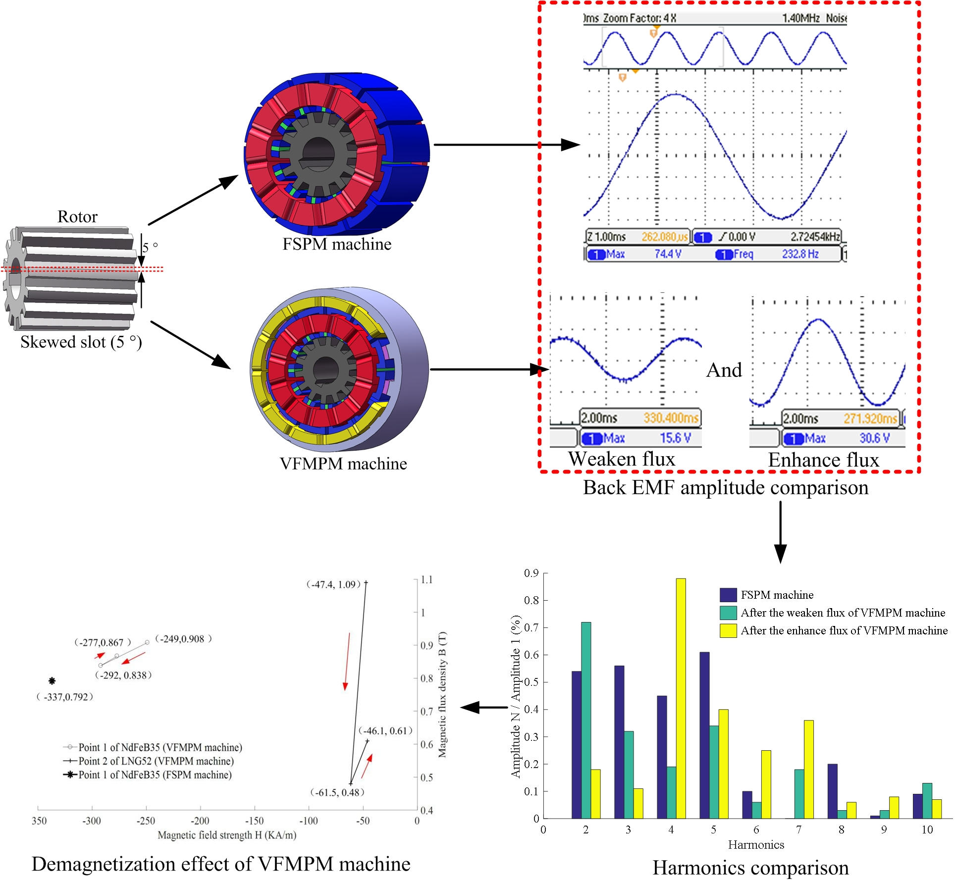
2. Back EMF Analysis of FSPM Machine and VFMPM Machine

In order to compare the back EMF waveforms of the FSPM machine and VFMPM machine, the corresponding relationship between the magnetic field distribution of machine and the relative position between stator and rotor was simulated by finite element analysis software. In view of the in-depth research on the back EMF waveforms of FSPM machine by professor W Hua et al. [20,21], this paper puts the main focus on the analysis of back EMF waveforms of the VFMPM machine, including the operation principle, straight slot and skewed-rotor structure of rotor, and magnetization and demagnetization of LNG52.

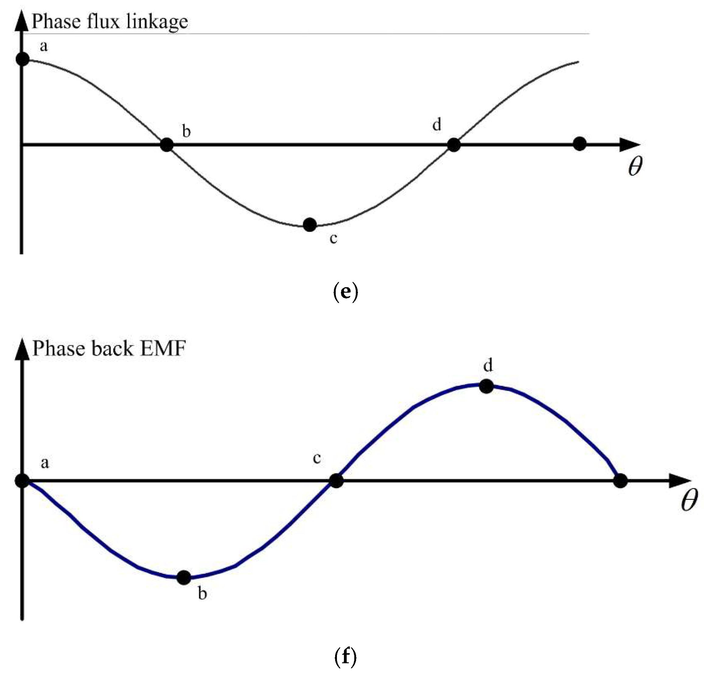
2.1. Operation Principle Analysis

Figure 2 shows an operation period of the back EMF waveform of the VFMPM machine, including the radial cross-section, relative position between rotor and stator, and flux linkage. It can be concluded from Figure 2 that the armature windings, field regulating windings, NdFe35 and LNG52 are installed in the stator. In addition, the magnetization direction of NdFe35 and LNG52 are tangential and radial, respectively.
The operation process of the back EMF waveform period can be divided into four main positions. When the relative position of rotor tooth (P point) and phase winding A1 is shown in Figure 2a, the flux linkage of phase A is maximum, as shown by point a in Figure 2e. Conversely, the flux linkage of phase A is minimum (point c in Figure 2e), since the relative position of rotor tooth (P point) and phase winding A1 is shown in Figure 2c. Figure 2b,d shows the zero-crossing of flux linkage, corresponding to point b and point d in Figure 2e.
Through the differential calculation of flux linkage in Figure 2e, the back EMF waveform of Phase A can be obtained, as shown in Figure 2f.
The purpose of field regulating windings is to inject the pulse current and then change the working point of LNG52. If the working point of LNG52 is changed, the air gap flux density between rotor and stator will also change. Simultaneously, the amplitude of back EMF waveform of the VFMPM machine can be increased or decreased, and this is referred to as enhance flux or weaken flux in some papers.

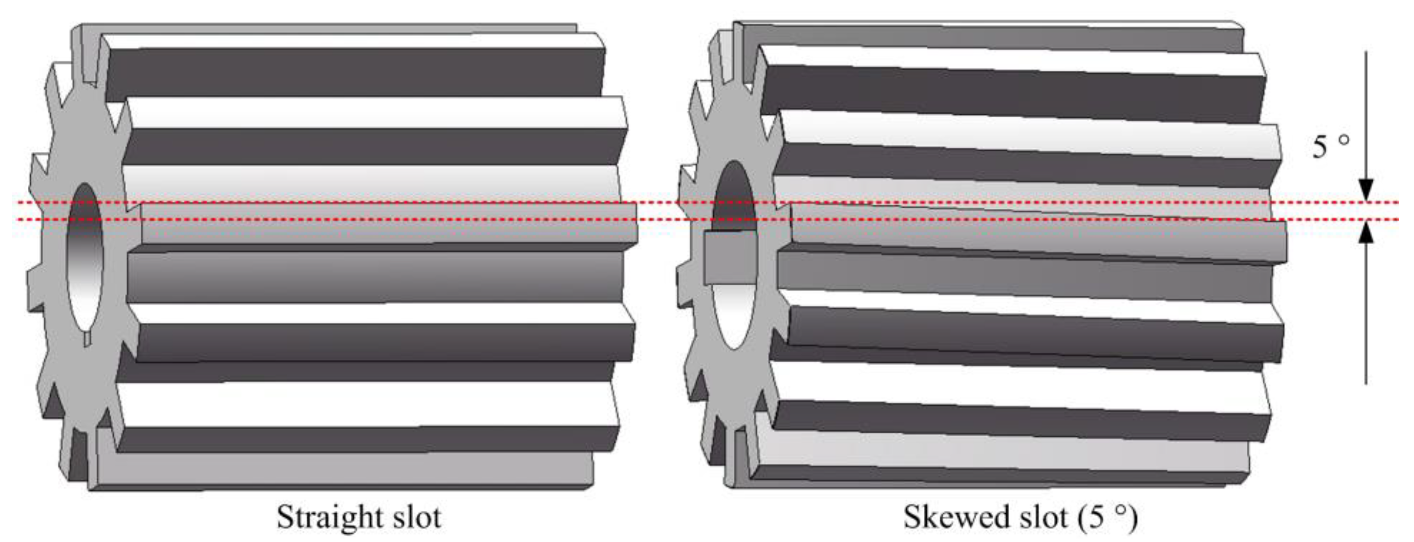
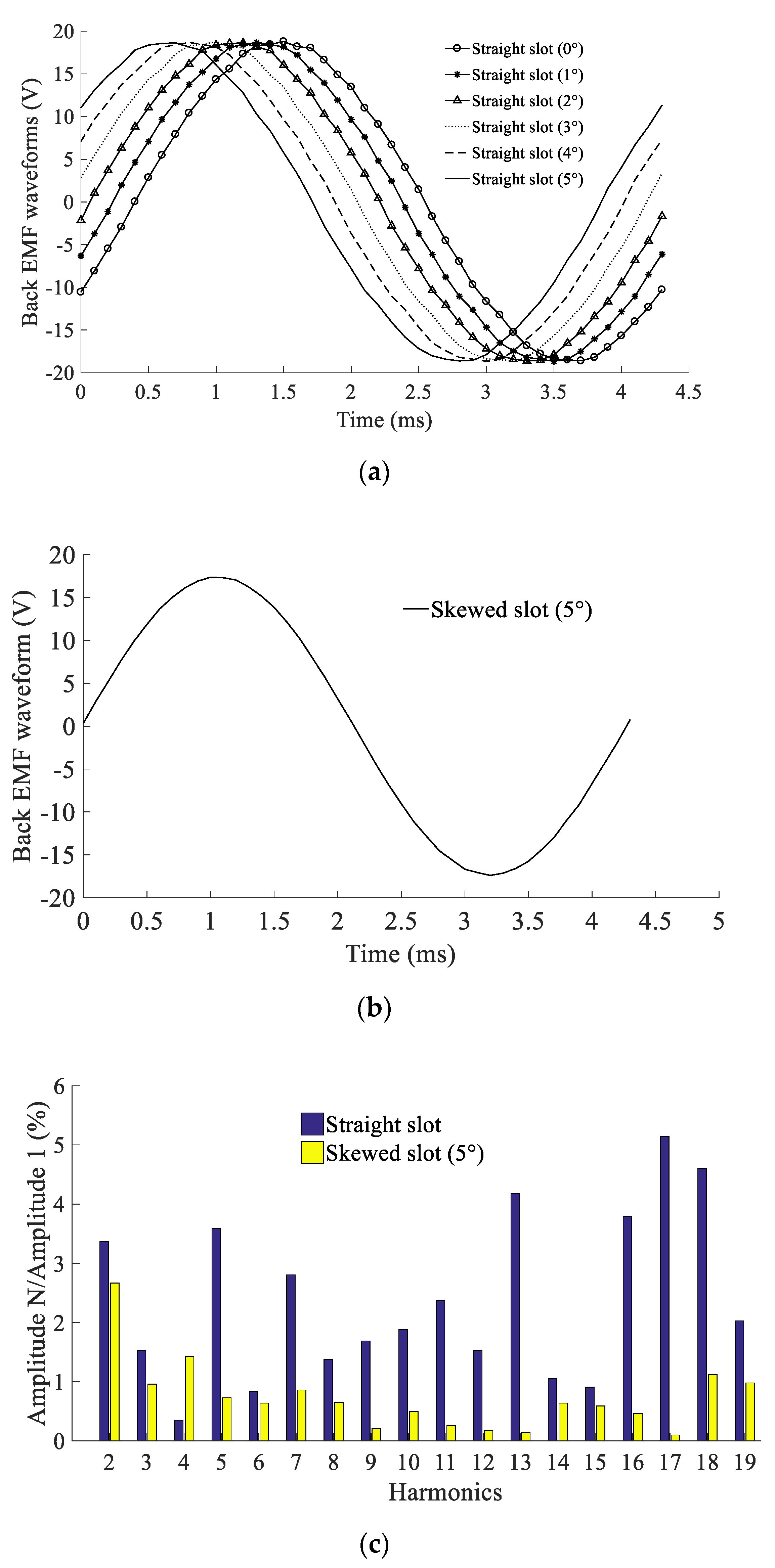
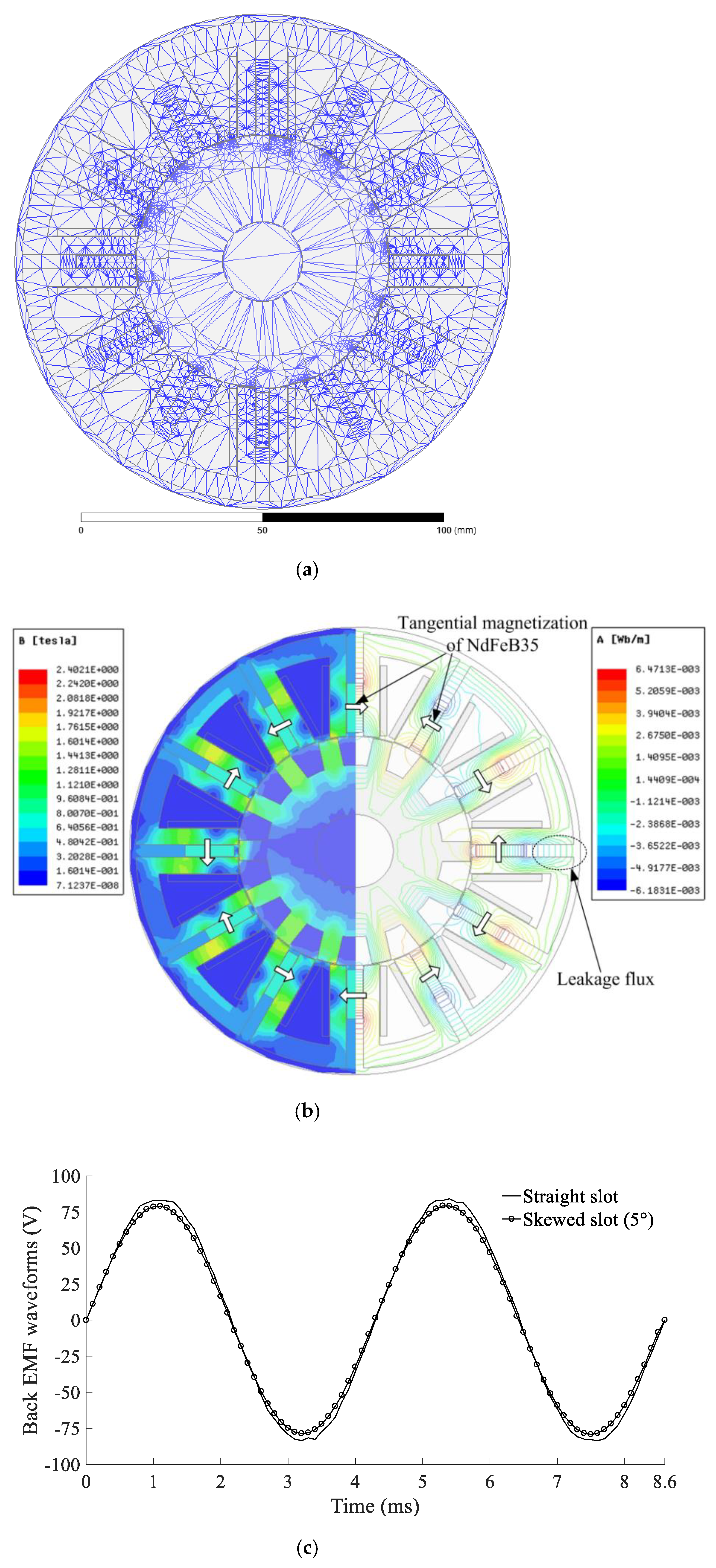
2.2. Back EMF Waveform Analysis of Machine with Straight Slot and Skewed Slot

The rotor structure of the FSPM machine and VFMPM machine is very simple (no embedded the windings or permanent magnet), and only the silicon steel sheets are superimposed around the motor shaft, as shown in Figure 3. Therefore, both the straight slot and skewed slot of the rotor are easy to manufacture and equip. However, compared with the straight slot of the rotor, the skewed slot of the rotor can improve the sinusoidal degree of back EMF waveforms.
The detailed theoretical research of skewed-slot-type rotor can be seen in References [22,23,24]. In this section, the discrepancy between the straight-slot-type rotor and skewed-slot-type rotor is discussed through simulation and harmonics analysis.
For the straight-slot-type rotor of the FSPM machine and VFMPM machine, if we divide the mechanical rotating degree θ into N equal parts, and simultaneously calculate the straight-slot-type back EMF waveform with different mechanical rotating degree 0 , θ / N , 2 θ / N , …, θ , the relationship between skewed-slot-type back EMF waveform and straight-slot-type back EMF waveform can be written as follows:
e s k ( θ ) = 1 N + 1 ( k = 0 N e s t ( θ k ) )
where e s k ( θ ) is the skewed-slot-type back EMF, e s t ( θ k ) is the straight-slot-type back EMF and θ k = k θ / N .
For example, under the condition of initial rotation degrees of straight slot, we get 0°, 1°, 2°, 3°, 4°and 5°, the six straight-slot-type back EMF waveforms of the VFMPM machine that are shown in Figure 4a. Then, if we calculate the average value of the abovementioned six straight slot-type-back EMF waveforms, the skewed-slot-type back EMF waveform of VFMPM machine with 5° can be achieved, as shown in Figure 4b. Therefore, the back EMF waveform relationship between the straight-slot type and skewed-slot type of the VFMPM machine is explained in Figure 4a,b.
Actually, Figure 4a,b shows the simulation results of back EMF waveform of VFMPM machine in the weaken flux condition, which is further elaborated in the latter section of this paper.
From the harmonics comparison of Figure 4c, it can be concluded that the harmonic contents of skewed-slot-type back EMF waveform are less than those of the straight slot type, which is beneficial for the optimization control and stable operation of machine.

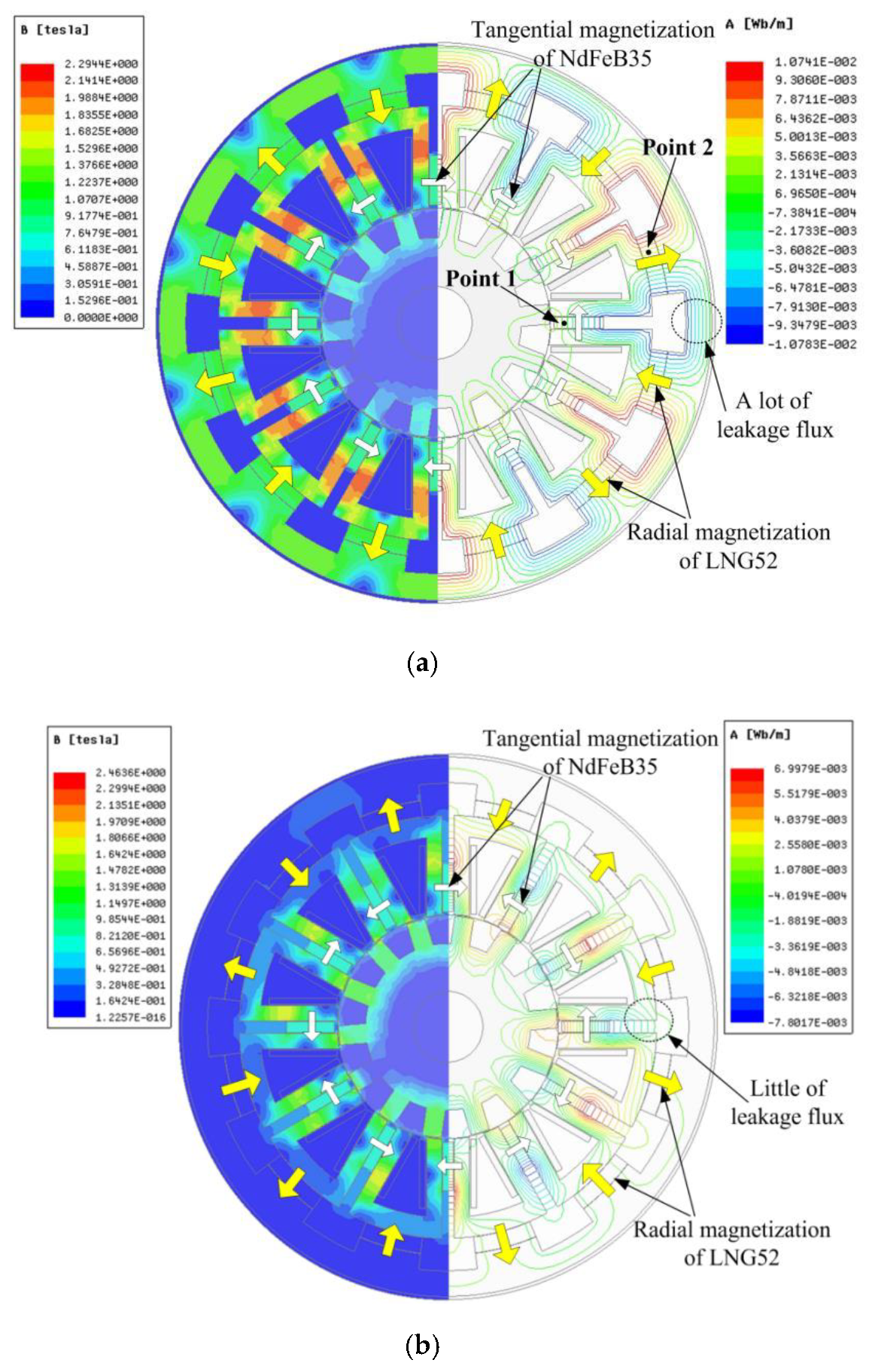
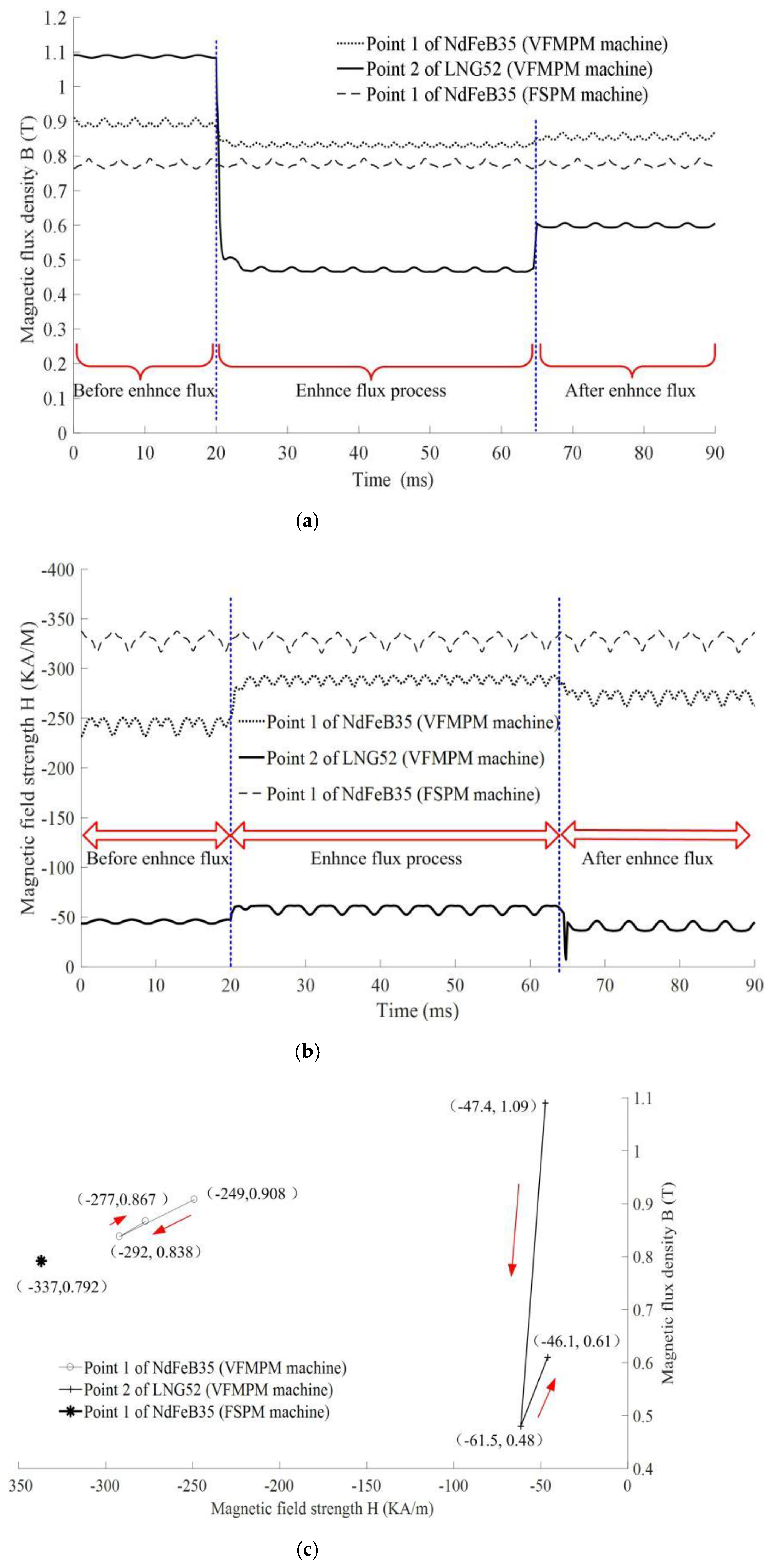
2.3. Magnetization and Demagnetization Analysis of LNG52

Compared with the FSPM machine, the VFMPM machine has an additional function of field regulating, which can be realized by the magnetization and demagnetization of permanent magnet material LNG52. As shown in Figure 1b and Figure 2a, the magnetization and demagnetization of LNG52 can be realized by the filed regulating windings, and the operational process is shown in Figure 5.
According to the electromagnetic theory of permanent magnet [25,26,27], Figure 5 indicates that the no-load working point of LNG52 can be shifted by changing the amplitude and direction of current of filed regulating windings. For example, after applying a negative pulse current with appropriate amplitude to the filed regulating windings, the no-load working point of LNG52 can be demagnetized from B 2 to B 3 . On the contrary, the no-load working point of LNG52 can be magnetized from B 3 to B 2 by the opposite current of filed regulating windings. If the amplitude of pulse current is large enough, the magnetization and demagnetization process can occur in the third and fourth quadrant of Figure 5 (not drawn).
Moreover, although the coercive force of LNG52 is much less than NdFe35’s, 56 and 625 kA/m respectively, the magnetization and demagnetization of LNG52 will have some influence on the working point of NdFe35, which can be verified by comparing the back EMF waveform amplitude between FSPM and VFMPM machine (see Section 5).

3. Simulation of FSPM Machine and VFMPM Machine

Through the analysis on back EMF waveforms, the simulation models for the FSPM machine and VFMPM machine were built respectively. The main dimension parameters of the FSPM machine and VFMPM machine are shown in Table 1. From Table 1, it can be seen that the main dimension parameters of the FSPM machine and VFMPM machine are the same, and the difference between the two kinds of machines lies in the installation of permanent magnet LNG52 and field regulating windings in the VFMPM machine, as shown in Figure 2a of FSPM machine.

3.1. Back EMF Waveforms of FSPM Machine with Straight Slot and Skewed Slot

Through the finite element analysis software ANSYS (a calculation and analysis software usually used in the hydrodynamics, circuit science, electromagnetism, etc.), Figure 6a illustrates the mesh dividing of FSPM machine. In Figure 6a, the surface deviation of mesh dividing is 0.44 mm, and the normal deviation of mesh dividing is 15 deg. Figure 6b is a simulation model of FSPM machine. The main elements are the copper of windings, permanent magnet NdFe35, iron core (DW360_50) of stator and rotor, and the vacuum of air gap. From Figure 6b, it can be seen that the maximum flux density is about 1.7 T~1.8 T, which has not reached the saturation state of DW360. Moreover, there is leakage flux outside the stator, and this is caused by the change of relative position between stator and rotor. However, the leakage flux cannot reduce the air-gap flux density dramatically, because the tangential magnetization of NdFeB35 improves the assembled magnetic effect between stator and rotor (air gap).
Based on the simulation model of Figure 6b, Figure 6c compares the back EMF waveforms of the FSPM machine with the straight-slot-type rotor and skewed-slot-type rotor (5 degree). It can be seen that the back EMF waveform of skewed-slot-type rotor is closer to sinusoidal than that of straight-slot-type rotor, but the back EMF waveform amplitude of the skewed-slot-type rotor is slightly smaller than that of the straight-slot-type rotor (79.5 and 82.9 V, respectively).
After normalization, Figure 6d shows the harmonics analysis of back EMF waveforms of straight-slot-type rotor and skewed-slot-type rotor (5 degree). From Figure 6d, it can be seen that the second, third, fifth, eleventh, fourteenth and sixteenth harmonics are very significant in the back EMF waveforms of the straight-slot-type rotor, and the second, third and fifth harmonics are the main components in the back EMF waveforms of skewed-slot-type rotor. In general, the total harmonic distortion (THD) of the back EMF waveforms of the FSPM machine with the skewed-slot-type rotor is 1.79%, which is less than that of the FSPM machine with the straight-slot-type rotor (5.6%).

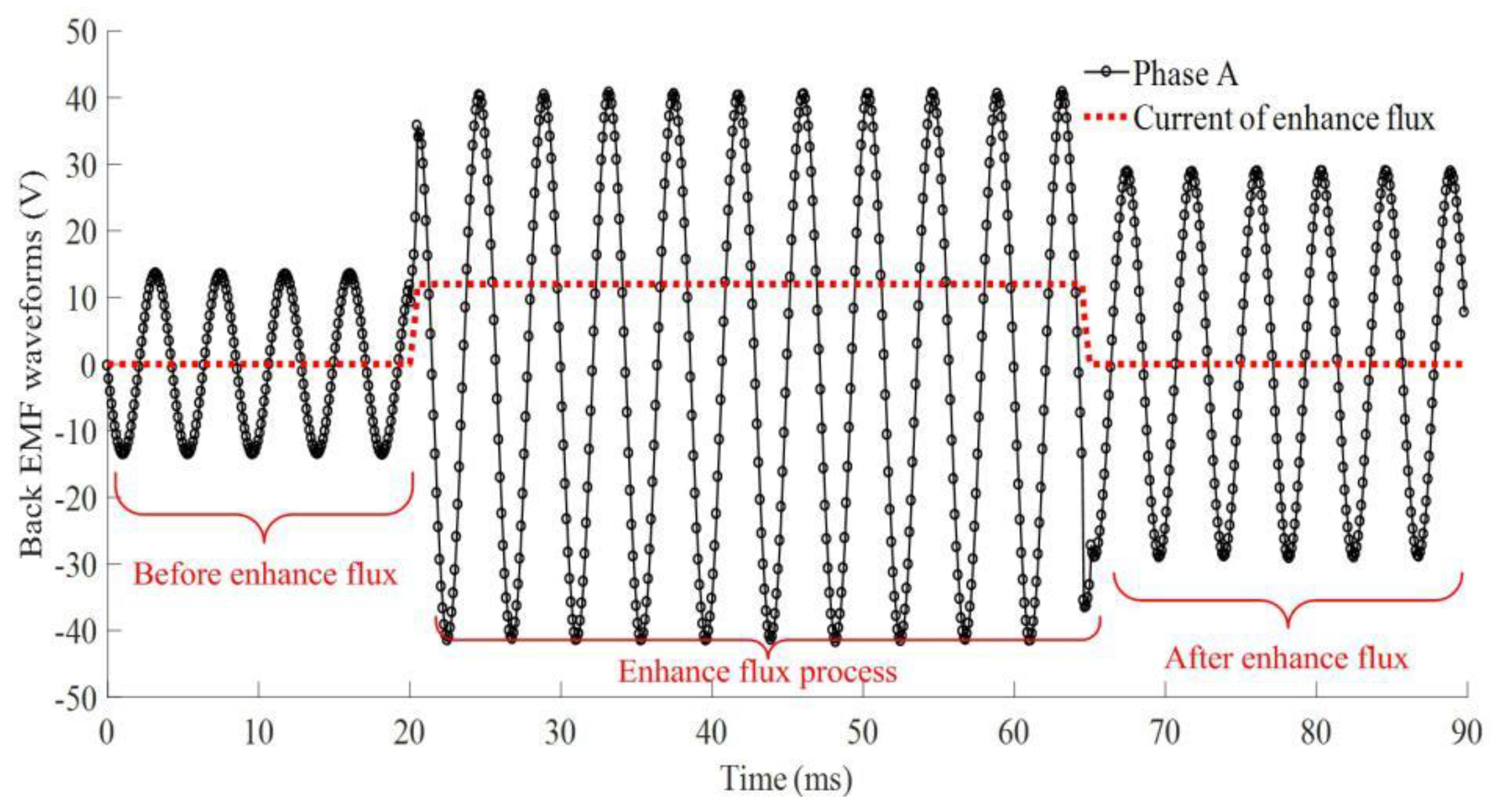
3.2. Back EMF Waveforms of VFMPM Machine with Skewed Slot

Due to the sinusoidal of back EMF waveform of skewed-slot-type rotor, the VFMPM machine’s rotor was designed as a skewed slot. Moreover, the same skewed slot of the rotor can enhance the comparability of the back EMF waveforms between the FSPM machine and VFMPM machine.
Figure 7 shows the simulation models of weaken flux condition (magnetization of LNG52) and enhance flux condition (demagnetization of LNG52) of the VFMPM machine, and the mesh division is the same as that of the FSPM machine. Different from the simulation model of the FSPM machine, the elements of permanent magnet LNG52 were added in the stator of VFMPM machine. In the weaken flux model of Figure 7a, a lot of leakage flux will occur between the outer stator and inner stator, and this will decrease the amplitude of the back EMF waveform of the VFMPM machine. On the contrary, in the enhance flux model of Figure 7b, the leakage flux is decreased and the amplitude of the back EMF waveform of VFMPM machine will be increased. In Figure 7b, the direction of magnetic field strength of LNG52 is just an ideal assumption, and it is analyzed in detail in Figure 12d of Section 5.
With the demagnetization of LNG52, Figure 8 shows the change of back EMF waveforms during the enhance flux process of the VFMPM machine. In Figure 8, the amplitude of the demagnetization pulse current (current of enhance flux) is 12 A, and the demagnetization current pulse width is 45 ms. After the demagnetization, the amplitude of the back EMF waveforms was increased from 13.68 to 29.2 V. In the enhance flux process, the amplitude of the back EMF waveforms is 39.5 V. Moreover, when the amplitude of demagnetization pulse current was increased to 15 A (or larger than 15 A), the amplitude of back EMF waveforms of VFMPM machine was about 32.5 V (no longer increasing). Therefore, for the skewed-slot-type rotor, the simulation results indicated that the maximum amplitude of the phase back EMF waveform of the FSPM machine was 245% larger than that of the VFMPM machine.
Moreover, the back EMF waveforms of the VFMPM machine under the weaken flux process are illustrated in Section 4 of this paper, and the harmonics comparison of the back EMF waveforms of Figure 8 (weaken flux condition and enhance flux condition) are illustrated in Reference [19].
For a detailed comparison between the simulation and experimental results, please refer to Reference [19].

4. Experimental Validation

In order to verify the results of the theoretical analysis and simulation, two prototypes of the FSPM machine and VFMPM machine with the same main dimensions and skewed-slot-type rotor were manufactured, as shown in Figure 9a. The parameters are shown in Table 1. Figure 9b shows the test rig of the back EMF waveforms.
Figure 10 shows the test results of the phase back EMF waveform of the FSPM machine and VFMPM machine. Both machines have a speed of 1000 r/min, driven by a servo motor. Figure 10a shows that the amplitude of the back EMF waveform of the FSPM machine is 74.4 V. After the enhance flux of the VFMPM machine by demagnetization current 12 A, the amplitude of the back EMF waveform of the VFMPM machine is 30.6 V, as shown in Figure 10b.
Furthermore, in the enhance process, if the demagnetization current was increased by more than 12 A, the amplitude of the phase back EMF waveform of the VFMPM machine could not be increased. Therefore, the experimental result showed that the maximum amplitude of the back EMF waveform of the FSPM machine was about 243% larger than that of the VFMPM machine’s.
The weaken flux process is illustrated in Figure 10c, where the minimum amplitude of the phase back EMF waveform of the VFMPM machine is 15.6 V (after the magnetization current 12 A), corresponding to the simulation result of Figure 4b.
Figure 11 shows the comparison of the harmonics (THD) of back EMF waveforms of the FSPM machine and VFMPM machine, including the weaken flux condition and enhance flux condition of VFMPM machine. From Figure 11, it can be seen that the second, third, fourth and fifth harmonics are the main harmonics of the FSPM machine and VFMPM machine (weaken flux condition), and the fourth, fifth, sixth and seventh harmonics account for the main harmonics of enhance flux condition of the VFMPM machine.
However, the THD of the FSPM machine and VFMPM machine are unanimity, including the weaken flux condition and enhance flux condition of the VFMPM machine, which are 2.56%, 2% and 2.39%, respectively.

5. Discussions of the Maximum Back EMF Waveform Amplitude Difference between FSPM Machine and VFMPM Machine

From the simulation and experimental results, it can be founded that the maximum amplitude of back EMF waveform of FSPM machine is larger than that of VFMPM machines. One reason for this phenomenon is that the mutual demagnetization effect occurred in the permanent magnets NdFeB35 and LNG52 of the VFMPM machine. The detailed analysis of the mutual demagnetization effect is as follows.
Firstly, two points in the NdFeB35 (point 1) and LNG52 (point 2) are selected respectively, as shown in Figure 7a, aiming at calculating their magnetic flux density (B) and magnetic field strength (H). Secondly, if LNG52 is not installed in the VFMPM machine, then the VFMPM machine can be regarded as an FSPM machine; the magnetic flux density (B) of NdFeB35 (point 1) is shown in Figure 12a. Thirdly, when LNG52 is installed in the VFMPM machine, the variation of magnetic flux density (B) of NdFeB35 (point 1) and LNG52 (point 2) during the enhance flux of the VFMPM machine is also shown in Figure 12a. Figure 12b shows the variation of magnetic field strength (H) of NdFeB35 (point 1) and LNG52 (point 2), corresponding to the Figure 12a.
Based on Figure 12a,b, Figure 12c shows the key variation of magnetic flux density (B) and magnetic field strength (H) of VFMPM machine. Figure 12a–c indicates that, when the enhance flux process (demagnetization of LNG52 by field regulating windings) is finished, the LNG52 is magnetized by the NdFeB35, and the magnetic flux density (B) of LNG52 (point 2) is increased from 0.48 to 0.61 T (magnetic field strength, H, is increased from −61.5 to −46.1 KA/m).
Furthermore, the total enhance flux process has some influence on the working point of NdFe35. The magnetic flux density (B) of NdFeB35 (point 1) is decreased from 0.908 to 0.867 T, and the magnetic field strength (H) is decreased from −249 to −277 KA/m.
Therefore, after the demagnetization of LNG52 by field regulating windings, the LNG52 will also be magnetized by the NdFeB35 simultaneously. This phenomenon explains why the amplitude of back EMF waveforms of the VFMPM machine is decreased from 39.5 to 29.2 V in Figure 8, and also presents the reason why the maximum amplitude of the back EMF waveform of the FSPM machine is larger than that of the VFMPM machine.
The above analysis also means that, under the effect of NdFeB35, the direction of the magnetic field strength (H) of LNG52 cannot be changed, but decreased, as shown in Figure 12d.
If we magnetize the permanent magnet LNG52 in the direction of yellow arrow of Figure 12d, then the weaken flux will occur in the VFMPM machine.

6. Conclusions

Based on the numerical simulation and experimental research, the back EMF waveforms of the FSPM machine and VFMPM machine with the same dimension were compared, including the amplitude and harmonics of back EMF waveforms. By comparison, it was founded that the maximum amplitude of the back EMF waveform of the FSPM machine was larger than that of the VFMPM machine, i.e., 245% and 243% in the simulation and experimental results, respectively. Furthermore, the harmonics of the back EMF waveforms of the FSPM machine and VFMPM machine were compared, including the enhance flux condition and weaken flux condition of the VFMPM machine, and the THDs were between 2% and 3%.
Moreover, the reason for the amplitude difference of the maximum back EMF waveform between the FSPM machine and VFMPM machine was analyzed, including the mutual demagnetization effect in the VFMPM machine. The detailed analysis and comparison of the two kinds of electrical machines will provide some qualitative advice for the application selection of the FSPM machine and VFMPM machine in electric vehicles (EVs), and may be beneficial for the optimization control of these two kinds of electrical machines to adopt the same method (not involves the magnetization and demagnetization of LNG52).
The comparison of the back EMF waveforms of these two kinds of electrical machines will provide some support for further research, including the comparison of the speed range, torque range, power density, dynamic performance and so on.

Author Contributions

Conceptualization, Y.C. and Z.C.; methodology, Y.C. and Z.C.; software, M.F. and Z.C.; validation, Y.C.; writing—original draft preparation, Y.C.; writing—review and editing, Z.C. All authors have read and agreed to the published version of the manuscript.

Funding

This work was financially supported by the Scientific and Technological Project in Henan Province, under Grant Nos. 212102210255, 212102210515 and 212102210516.

Institutional Review Board Statement

Not applicable.

Informed Consent Statement

Not applicable.

Data Availability Statement

Some or all data and models generated or used during the study are available in a repository or online.

Acknowledgments

Y.C. and Z.C. were supported by the Henan Equipment Manufacturing Internet of Things Big Data Analysis and Application Engineering Research Center. M.F. received a research scholarship form the cooperative training project of COMSATS University Islamabad and Huanghuai University.

Conflicts of Interest

The authors declare no conflict of interest.

References

  1. Cao, R.; Lu, M. Reduction of Thrust Force Ripple of High Temperature Superconducting Linear Flux-Switching Motors using Asymmetry Mover Structure. IEEE Trans. Appl. Supercond. 2021, 31, 5200905. [Google Scholar] [CrossRef]
  2. Chen, H.; El-Refaie, A.M.; Demerdash, N.A.O. Flux-Switching Permanent Magnet Machines: A Review of Opportunities and Challenges—Part I: Fundamentals and Topologies. IEEE Trans. Energy Convers. 2020, 35, 684–698. [Google Scholar] [CrossRef]
  3. Huang, W.; Hua, W.; Yin, F.; Yu, F.; Qi, J. Model Predictive Thrust Force Control of a Linear Flux-Switching Permanent Magnet Machine With Voltage Vectors Selection and Synthesis. IEEE Trans. Ind. Electron. 2018, 66, 4956–4967. [Google Scholar] [CrossRef]
  4. Ullah, W.; Khan, F.; Sulaiman, E.; Umair, M.; Ullah, N.; Khan, B. Analytical validation of novel consequent pole E-core stator permanent magnet flux switching machine. IET Electr. Power Appl. 2020, 14, 789–796. [Google Scholar] [CrossRef]
  5. Kim, J.H.; Li, Y.; Sarlioglu, B. Sizing, Analysis, and Verification of Axial Flux-Switching Permanent Magnet Machine. IEEE Trans. Ind. Appl. 2019, 55, 3512–3521. [Google Scholar] [CrossRef]
  6. Li, W.; Chen, M. Reliability Analysis and Evaluation for Flux-Switching Permanent Magnet Machine. IEEE Trans. Ind. Electron. 2019, 66, 1760–1769. [Google Scholar] [CrossRef]
  7. Ding, Q.; Ni, T.; Wang, X.; Deng, Z. Optimal Winding Configuration of Bearingless Flux-Switching Permanent Magnet Motor With Stacked Structure. IEEE Trans. Energy Convers. 2017, 33, 78–86. [Google Scholar] [CrossRef]
  8. Su, P.; Hua, W.; Wu, Z.; Chen, Z.; Zhang, G.; Cheng, M. Comprehensive Comparison of Rotor-Permanent Magnet and Stator-Permanent Magnet Flux-Switching Machines. IEEE Trans. Ind. Electron. 2018, 66, 5862–5871. [Google Scholar] [CrossRef]
  9. Awah, C.C. Effect of permanent magnet material on the electromagnetic performance of switched-flux permanent magnet machine. Electr. Eng. 2021, 103, 1647–1660. [Google Scholar] [CrossRef]
  10. Zhu, J.; Wu, L.; Zheng, W.; Zhou, Q.; Li, T. Magnetic Circuit Modeling of Dual-Armature Flux-Switching Permanent Magnet Machine. IEEE Trans. Magn. 2021, 57, 8100513. [Google Scholar] [CrossRef]
  11. Yu, J.; Liu, C. DC-Biased Operation of a Double-Stator Hybrid Flux Switching Permanent-Magnet Machine. IEEE Trans. Magn. 2020, 56, 7505106. [Google Scholar] [CrossRef]
  12. Fard, J.R.; Ardebili, M. Design and Control of a Novel Yokeless Axial Flux-Switching Permanent-Magnet Motor. IEEE Trans. Energy Convers. 2018, 34, 631–642. [Google Scholar] [CrossRef]
  13. Lyu, S.; Yang, H.; Lin, H.; Zhu, Z.Q.; Zheng, H.; Pan, Z. Influence of Design Parameters on On-Load Demagnetization Characteristics of Switched Flux Hybrid Magnet Memory Machine. IEEE Trans. Magn. 2019, 55, 1–5. [Google Scholar] [CrossRef]
  14. Yang, H.; Lyu, S.; Lin, H.; Zhu, Z.Q.; Peng, F.; Zhuang, E.; Fang, S.; Huang, Y. Stepwise Magnetization Control Strategy for DC-Magnetized Memory Machine. IEEE Trans. Ind. Electron. 2018, 66, 4273–4285. [Google Scholar] [CrossRef] [Green Version]
  15. Yang, G.; Lin, M.; Li, N.; Hao, L. Magnetization State Regulation Characteristic Study of Series Hybrid Permanent Magnet Axial Field Flux-Switching Memory Machine. IEEE Trans. Appl. Supercond. 2019, 29, 1–6. [Google Scholar] [CrossRef]
  16. Guo, L.; Geng, Q.; Chen, W.; Wang, H. Optimal design for low iron-loss variable flux permanent magnet memory machine. Int. J. Appl. Electromagn. Mech. 2020, 63, 299–313. [Google Scholar] [CrossRef]
  17. Zhu, Z.Q.; Hua, H.; Pride, A.; Deodhar, R.; Sasaki, T. Analysis and Reduction of Unipolar Leakage Flux in Series Hybrid Permanent-Magnet Variable Flux Memory Machines. IEEE Trans. Magn. 2017, 53, 1–4. [Google Scholar] [CrossRef]
  18. Zhu, X.; Fan, D.; Mo, L.; Chen, Y.; Quan, L. Multiobjective Optimization Design of a Double-Rotor Flux-Switching Permanent Magnet Machine Considering Multimode Operation. IEEE Trans. Ind. Electron. 2019, 66, 641–653. [Google Scholar] [CrossRef]
  19. Chen, Z.; Cui, Y. Numerical Simulation and Experimental Validation of a Flux Switching Permanent Magnet Memory Machine. IEEE Access 2020, 8, 194904–194911. [Google Scholar] [CrossRef]
  20. Zhu, X.; Hua, W. Back-EMF waveform optimization of flux-reversal permanent magnet machines. AIP Adv. 2017, 7, 056613. [Google Scholar] [CrossRef] [Green Version]
  21. Zhang, H.; Hua, W.; Zhang, G. Analysis and optimization of back-EMF waveform of a novel outer-rotor-permanent-magnet flux-switching machine. In Proceedings of the 2016 IEEE Conference on Electromagnetic Field Computation (CEFC), Miami, FL, USA, 13–16 November 2016. [Google Scholar] [CrossRef]
  22. Roekke, A.; Nilssen, R. Analytical Calculation of Yoke Flux Patterns in Fractional-Slot Permanent Magnet Machines. IEEE Trans. Magn. 2016, 53, 1–9. [Google Scholar] [CrossRef]
  23. Arabul, F.K.; Senol, I.; Oner, Y. Performance Analysis of Axial-Flux Induction Motor with Skewed Rotor. Energies 2020, 13, 4991. [Google Scholar] [CrossRef]
  24. Xu, W.; Bao, X.; Xu, S.; Li, Z. Design of Dual Skewed Rotor in Cage Induction Motor for Reducing Synchronous Parasitic Torque. J. Magn. 2019, 24, 142–148. [Google Scholar] [CrossRef] [Green Version]
  25. Yang, G.; Fu, X.; Lin, M.; Li, N.; Li, H. Comparative Study of Flux Regulation Methods for Hybrid Permanent Magnet Axial Field Flux-switching Memory Machines. J. Power Electron. 2019, 19, 158–167. [Google Scholar]
  26. Hu, Y.; Chen, B.; Xiao, Y.; Li, X.; Zhang, Z.; Shi, J.; Li, L. Research and Design on Reducing the Difficulty of Magnetization of a Hybrid Permanent Magnet Memory Motor. IEEE Trans. Energy Convers. 2020, 35, 1. [Google Scholar] [CrossRef]
  27. Reigosa, D.; Fernández, D.; Park, Y.; Diez, A.B.; Lee, S.B.; Briz, F. Detection of Demagnetization in Permanent Magnet Synchronous Machines Using Hall-Effect Sensors. IEEE Trans. Ind. Appl. 2018, 54, 3338–3349. [Google Scholar] [CrossRef]
Figure 1. Two kinds of flux switching machines. (a) FSPM machine; (b) VFMPM machine.
Wevj 12 00149 g001
Figure 2. Relative position between rotor and stator of VFMPM machine, and the corresponding variation of flux linkage and phase back EMF. (a) Position a; (b) Position b; (c) Position c; (d) Position d; (e) Phase flux linkage waveform; (f) Phase back EMF waveform.
Wevj 12 00149 g002aWevj 12 00149 g002b
Figure 3. Straight-slot-type and skewed-slot-type rotors.
Wevj 12 00149 g003
Figure 4. Back EMF waveform analysis of VFMPM machine. (a) Straight-slot-type back EMF waveforms (0°, 1°, 2°, 3°, 4° and 5° are the initial rotation degrees of rotor); (b) Skewed-slot-type back EMF waveform; (c) Back EMF harmonics comparison of straight-slot type and skewed-slot type.
Wevj 12 00149 g004
Figure 5. Magnetization and demagnetization of LNG52.
Wevj 12 00149 g005
Figure 6. Simulation model and back EMF waveform comparison. (a) Mesh dividing; (b) Simulation model; (c) Comparison of back EMF waveforms (1000 r/min); (d) Harmonics comparison of back EMF waveforms.
Wevj 12 00149 g006aWevj 12 00149 g006b
Figure 7. Simulation models of weaken flux and enhance flux. (a) Weaken flux model of VFMPM machine (magnetization of LNG52); (b) Enhance flux model of VFMPM machine (demagnetization of LNG52).
Wevj 12 00149 g007
Figure 8. Enhance flux process of VFMPM machine.
Wevj 12 00149 g008
Figure 9. Prototype and test rig. (a) Prototype; (b) Test rig of back EMF waveforms.
Wevj 12 00149 g009
Figure 10. Back EMF waveforms of FSPM machine and VFMPM machine. (a) Back EMF waveform of FSPM machine; (b) Back EMF waveform of VFMPM machine after enhance flux; (c) Back EMF waveform of VFMPM machine after weaken flux.
Wevj 12 00149 g010
Figure 11. Harmonics comparison of back EMF waveforms of the FSPM machine and VFMPM machine.
Wevj 12 00149 g011
Figure 12. Detailed analysis of mutual demagnetization effect in VFMPM machine. (a) Variation of magnetic flux density (B); (b) Variation of magnetic field strength (H); (c) Key variation of magnetic flux density (B) and magnetic field strength (H); (d) Decrease of magnetic field strength of LNG52.
Wevj 12 00149 g012aWevj 12 00149 g012b
Table 1. Main dimension parameters of FSPM machine and VFMPM machine.
DescriptionsFSPMVFMPM
StatorOuter radius65.5 mm79.2 mm
Inner radius35 mm35 mm
Tooth width8.22 deg8.22 deg
Axial length75 mm75 mm
Quantity of slots1212
Materials (iron core)DW360_50DW360_50
RotorOuter radius34.5 mm34.5 mm
Tooth width10 deg10 deg
Axial length75 mm75 mm
Poles1414
Materials (iron core)DW360_50DW360_50
NdFeB35Thick3.5 mm3.5 mm
Length15 mm15 mm
Magnet coercive force625 kA/m625 kA/m
LNG52LengthNone12 mm
ThickNone5 mm
Magnet coercive forceNone56 kA/m
OthersAir gap wide0.5 mm0.5 mm
Turns of armature winding per phase140140
Turns of field regulating winding per LNG52None60
Maximum current of field regulating windingNone15 A
DC-link voltage220 A220 A
Rated current 5 A rms5 A rms
Resistance per phase0.9 Ω0.9 Ω
Rated power (approximate value)1 kW1 kW
Rated speed3000 rpm3000 rpm
Publisher’s Note: MDPI stays neutral with regard to jurisdictional claims in published maps and institutional affiliations.

