
On-Board Liquid Hydrogen Cold Energy Utilization System for a Heavy-Duty Fuel Cell Hybrid Truck


Abstract
:1. Introduction
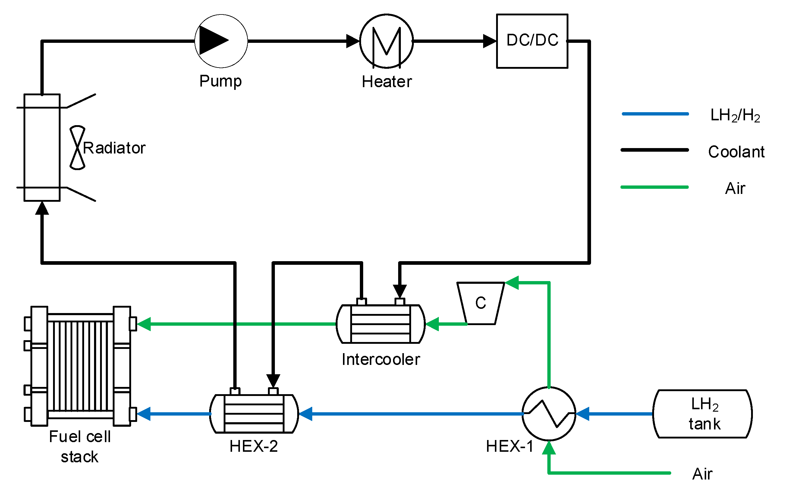
2. Configuration Design
3. Methodology
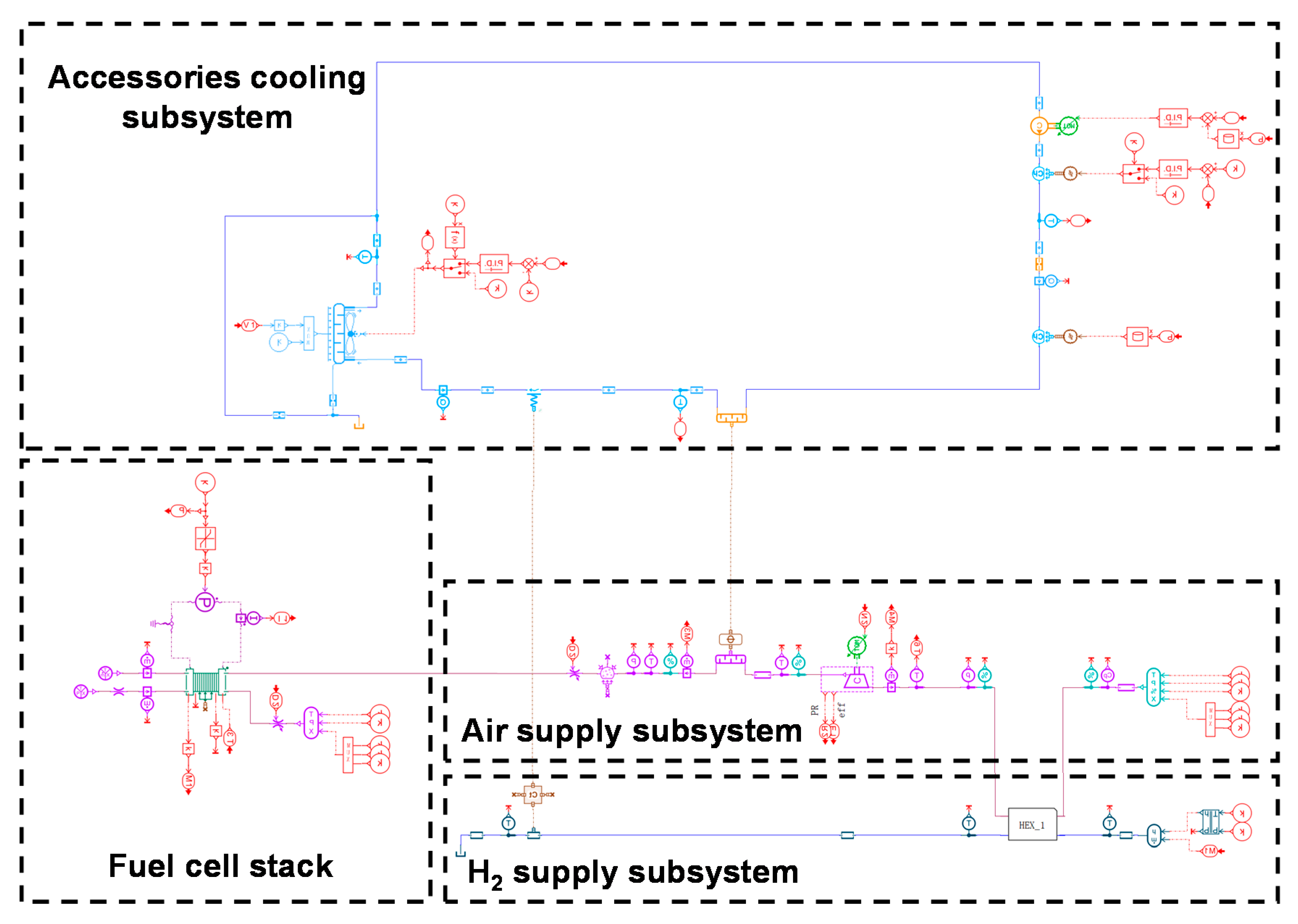
3.1. System Model
3.1.1. Fuel Cell Stack Model
3.1.2. H2 Supply Subsystem
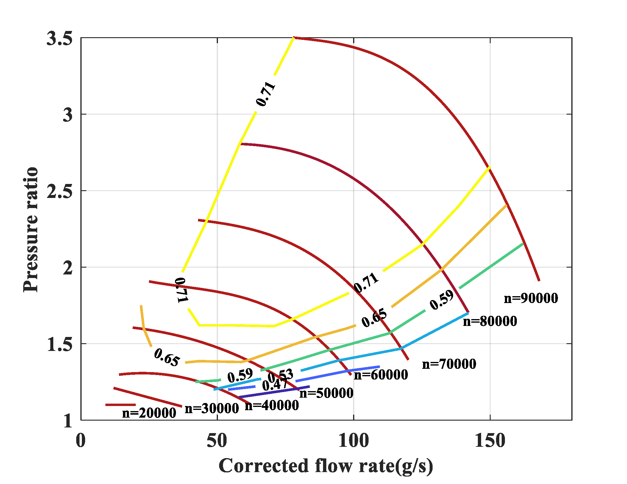
3.1.3. Air Supply Subsystem
3.1.4. Accessories Cooling Subsystem
3.2. Cold Energy Utilization Ratio Analysis
3.3. Parasitic Power Analysis
4. Results and Discussion
4.1. Cold Energy Utilization Ratio Results
4.2. Parasitic Power Saving Results
5. Conclusions
Author Contributions
Funding
Institutional Review Board Statement
Informed Consent Statement
Data Availability Statement
Acknowledgments
Conflicts of Interest
Nomenclature
| Parameters and variables | |
| E | Energy, J |
| F | Faraday constant, C/mol |
| h | Enthalpy, J/kg |
| I | Current, A |
| m | Mass, kg |
| Mass flow rate, kg/s | |
| M | relative molecular mass |
| N | Number |
| P | Power, W |
| S | Stoichiometric ratio |
| V | Electric potential, V |
| Efficiency | |
| Mass fraction of O2 in air | |
| Subscripts | |
| act | Activation |
| air | Air |
| cell | Fuel cell |
| comp | Compressor |
| conc | Convection |
| coolant | Coolant |
| demand | Cooling demand |
| extra | Excessive cold energy |
| fan | Radiator fan |
| heater | Heater |
| H2 | Hydrogen |
| LH2 | Liquid hydrogen |
| nernst | Nernst voltage |
| ohmic | Ohmic |
| O2 | Oxygen |
| pump | Water pump |
| total | Total parasitic power |
| used | Used cold energy |
| 1 | Heat exchanger 1 |
| 2 | Heat exchanger 2 |
References
- Li, M.; Bai, Y.; Zhang, C.; Song, Y.; Jiang, S.; Grouset, D.; Zhang, M. Review on the research of hydrogen storage system fast refueling in fuel cell vehicle. Int. J. Hydrogen Energy 2019, 44, 10677–10693. [Google Scholar] [CrossRef] [Green Version]
- Abe, J.O.; Popoola, A.P.I.; Ajenifuja, E.; Popoola, O.M. Hydrogen energy, economy and storage: Review and recommendation. Int. J. Hydrogen Energy 2019, 44, 15072–15086. [Google Scholar] [CrossRef]
- Helmolt, R.V.; Eberle, U. Compressed and Liquid Hydrogen for Fuel Cell Vehicles. In Encyclopedia of Applied Electrochemistry; Springer: Berlin/Heidelberg, Germany, 2014; pp. 245–253. [Google Scholar] [CrossRef]
- Wang, Q.; Li, J.; Bu, Y.; Xu, L.; Qin, Z. Technical assessment and feasibility validation of liquid hydrogen storage and supply system for heavy-duty fuel cell truck. In Proceedings of the 2020 4th CAA International Conference on Vehicular Control and Intelligence (CVCI), Hangzhou, China, 18–20 December 2020. [Google Scholar]
- Cardella, U.; Decker, L.; Klein, H. Roadmap to economically viable hydrogen liquefaction. Int. J. Hydrogen Energy 2017, 42, 13329–13338. [Google Scholar] [CrossRef]
- Yilmaz, C. A case study: Exergoeconomic analysis and genetic algorithm optimization of performance of a hydrogen liquefaction cycle assisted by geothermal absorption precooling cycle. Renew Energy 2018, 128, 68–80. [Google Scholar] [CrossRef]
- Cardella, U.; Decker, L.; Sundberg, J.; Klein, H. Process optimization for large-scale hydrogen liquefaction. Int. J. Hydrogen Energy 2017, 42, 12339–12354. [Google Scholar] [CrossRef]
- Krasae-In, S.; Stang, J.H.; Neksa, P. Development of large-scale hydrogen liquefaction processes from 1898 to 2009. Int. J. Hydrogen Energy 2010, 35, 4524–4533. [Google Scholar] [CrossRef]
- Kanbur, B.B.; Xiang, L.; Dubey, S.; Choo, F.H.; Duan, F. Cold utilization systems of LNG: A review. Renew. Sustain. Energy Rev. 2017, 79, 1171–1188. [Google Scholar] [CrossRef]
- He, T.; Chong, Z.R.; Zheng, J.; Ju, Y.; Linga, P. LNG cold energy utilization: Prospects and challenges. Energy 2019, 170, 557–568. [Google Scholar] [CrossRef]
- Liu, Y.; Han, J.; You, H. Performance analysis of a CCHP system based on SOFC/GT/CO2 cycle and ORC with LNG cold energy utilization. Int. J. Hydrogen Energy 2019, 44, 29700–29710. [Google Scholar] [CrossRef]
- Trevisani, L.; Fabbri, M.; Negrini, F.; Ribani, P.L. Advanced energy recovery systems from liquid hydrogen. Energy Convers. Manag. 2007, 48, 146–154. [Google Scholar] [CrossRef]
- ZHANG, N.; LIOR, N. A novel Brayton cycle with the integration of liquid hydrogen cryogenic exergy utilization. Int. J. Hydrogen Energy 2008, 33, 214–224. [Google Scholar] [CrossRef]
- Simcenter Amesim. Available online: https://www.plm.automation.siemens.com/global/en/products/simcenter/simcenter-amesim.html (accessed on 16 August 2021).


| Parameter | Value |
|---|---|
| Fuel cell stack nominal power (kW) | 100 |
| DC/DC efficiency (%) | 95 |
| Fuel cell stack load range (%) | 25~100 |
| Ambient temperature range (°C) | −30~40 |
| Ambient humidity (%) | 40 |
| Maximum radiator fan power (kW) | 0.5 |
| DC/DC inlet coolant temperature control point (°C) | 50 |
| HEX-1 inlet H2 temperature (°C) | −220 |
| Coolant flow rate range (L/min) | 50~90 |
Publisher’s Note: MDPI stays neutral with regard to jurisdictional claims in published maps and institutional affiliations. |
© 2021 by the authors. Licensee MDPI, Basel, Switzerland. This article is an open access article distributed under the terms and conditions of the Creative Commons Attribution (CC BY) license (https://creativecommons.org/licenses/by/4.0/).
Share and Cite
Yang, M.; Hu, S.; Yang, F.; Xu, L.; Bu, Y.; Yuan, D. On-Board Liquid Hydrogen Cold Energy Utilization System for a Heavy-Duty Fuel Cell Hybrid Truck. World Electr. Veh. J. 2021, 12, 136. https://doi.org/10.3390/wevj12030136
Yang M, Hu S, Yang F, Xu L, Bu Y, Yuan D. On-Board Liquid Hydrogen Cold Energy Utilization System for a Heavy-Duty Fuel Cell Hybrid Truck. World Electric Vehicle Journal. 2021; 12(3):136. https://doi.org/10.3390/wevj12030136
Chicago/Turabian StyleYang, Mingye, Song Hu, Fuyuan Yang, Liangfei Xu, Yu Bu, and Dian Yuan. 2021. "On-Board Liquid Hydrogen Cold Energy Utilization System for a Heavy-Duty Fuel Cell Hybrid Truck" World Electric Vehicle Journal 12, no. 3: 136. https://doi.org/10.3390/wevj12030136