Article

Online Parameters Identification and State of Charge Estimation for Lithium-Ion Battery Using Adaptive Cubature Kalman Filter

1
Hubei Key Laboratory of Advanced Technology for Automotive Components, Wuhan University of Technology, Wuhan 430070, China
2
Hubei Collaborative Innovation Center for Automotive Components Technology, Wuhan University of Technology, Wuhan 430070, China
3
Key Laboratory of Electrochemical Energy Storage and Energy Conversion of Hainan Province, College of Physics and Electronic Engineering, Hainan Normal University, Haikou 571158, China
*
Author to whom correspondence should be addressed.
World Electr. Veh. J. 2021, 12(3), 123; https://doi.org/10.3390/wevj12030123
Submission received: 19 July 2021 / Revised: 9 August 2021 / Accepted: 16 August 2021 / Published: 17 August 2021

Abstract

:
The state of charge (SOC) of a lithium-ion battery plays a key role in ensuring the charge and discharge energy control strategy, and SOC estimation is the core part of the battery management system for safe and efficient driving of electric vehicles. In this paper, a model-based SOC estimation strategy based on the Adaptive Cubature Kalman filter (ACKF) is studied for lithium-ion batteries. In the present study, the dual polarization (DP) model is employed for SOC estimation and the vector forgetting factor recursive least squares (VRLS) method is utilized for model parameter online identification. The ACKF is then designed to estimate the battery’s SOC. Finally, the Urban Dynamometer Driving Schedule and Dynamic Stress Test are utilized to evaluate the performance of the proposed method by comparing with results obtained using the extended Kalman filter (EKF) and the cubature Kalman filter (CKF) algorithms. The simulation and experimental results show that the proposed ACKF algorithm combined with VRLS-based model identification is a promising SOC estimation approach. The proposed algorithm is found to provide more accurate SOC estimation with satisfying stability than the extended EKF and CKF algorithms.

1. Introduction

Faced with the global energy shortage and climate change crisis, the market position of electric vehicles (EVs) has become obvious [1,2], leading the trend of the automotive industry with the advantages of being pollution-free, low noise, and having high energy efficiency [3,4]. Among all commercially available lithium-ion batteries, the ternary lithium-ion batteries are widely utilized because of their advantages of long service life, high energy density, superior performance at high and low temperatures, and environmental protection [5]. However, under certain operating conditions, the difference among all individual cells may result in battery over-charge and over-discharge, even explosions [6]. Therefore, the Battery Management System (BMS) plays a crucial role in assuring safety and monitoring the operating process [7,8]. State of charge (SOC), which indicates the remaining energy in the battery, is an important part of BMS [9]. The SOC of a battery cannot be obtained directly but is often estimated based on some measurable parameters such as the terminal voltage and operation current [10]. Thus, SOC estimation is still a challenging research topic.
SOC estimation algorithms can be classified into two categories: non-model-based and model-based [11]. Two commonly used non-model-based SOC estimation approaches are the Ampere-hour (Ah) integration method [12,13], and the open-circuit voltage (OCV) method [14]. The Ah integration method obtains the SOC by integrating the current over time. The accuracy of the ampere-hour integration method depends on the measured current value and the initial SOC value and high accuracy of the current sensor is required. Moreover, since accurate data of real-time initial SOC value cannot be obtained easily in operating EVs, this method is not ideal for practical applications. On the other hand, although accurate SOC value can be obtained using the open-circuit voltage method, it cannot perform online tests of SOC [15]. The OCV method acquires the SOC based on the relationship between OCV and SOC. The OCV method is used for the initial calibration of SOC in many BMS systems. However, this method requires long periods of standing of the battery before measurement, and the operating conditions are only suitable for laboratories and cannot be applied to the changing operating conditions of EVs.
Compared with the above-mentioned non-model-based methods, the model-based methods are more promising for EV application. The process of these approaches can be divided into three procedures: model building, identification of model parameters, and SOC estimation [6]. Many battery models have been reported to date, e.g., the electrochemical model [16], equivalent circuit models (ECMs) [17,18], and neural network models [19,20,21,22]. The electrochemical model is rather complex and requires a large number of parameters for SOC estimation [16]. The neural network models [19] require vast training data of all driving conditions for accurate estimation. In contrast, the equivalent battery models (ECMs) are widely used for their ease of implementation [23]. The ECMs describe the battery’s behavior by basic electric components such as resistors and capacitors. Some well-known ECMs are the Thevenin model [24,25], DP model [26], and PNGV (Partnership for a New Generation of Vehicle) model. Hu et al. [27] analyzed 12 lithium-ion battery equivalent circuit models and proposed that the selection of the model should take into consideration accuracy and simplicity, and models of higher than the second order only had high accuracy in theory. By comparing the estimated terminal voltage values obtained from using the Thevenin model, the DP model, and the PNGV model under different operating conditions, Wang et al. [28] found that the accuracy and dynamic performance of the DP model were better than the other two models. Thus, in view of accuracy and simplicity, the DP model is chosen for the present study.
The parameters of ECMs should be identified after building the battery model. Offline and online identification are two major approaches [29]. Offline identification, as the name suggests, obtains the parameters as a function of SOC by identifying the parameters through experiments of certain working conditions, such as the hybrid pulse power characterization (HPPC) test. In Ref. [30], through real-time measurement and update of the battery voltage and current, the battery parameters were accurately identified by HPPC test to guarantee a reliable battery state estimate. However, the offline method based on certain conditions relies on a large number of experiments, which requires long development cycles and high costs. On the other hand, online identification only acquires new parameters that correspond to the present battery state through the latest inputs, hence, the performance of SOC estimation is better [31,32]. This method mainly includes the filter type [33,34,35] and the recursive least square (RLS) type. Yu et al. [35] used the H-infinity filter to update battery parameters, and the multi-scale EKF was adopted to estimate the system parameters. In contrast, the RLS [36] method has been used widely because it is easy to implement and the requirement of calculation is low. The RLS method is based on real-time observations and uses filtering theory to update model parameters online. However, update of data will result in the accumulation of old data; thus, it would be hard to track the parameters of a time-variant system. The adoption of the forgetting factor reduces the accumulation of past data and provides a calculation basis for supplementing new data [37]. Ze et al. [38] used the forgetting factor recursive least squares (FFRLS) algorithm to identify 3 parameters of the Thevenin model. In [9], good performance was obtained using the least squares method (LS) with a forgetting factor in parameter identification of DP model. It is noted that if the forgetting factor remains unchanged, the ability and accuracy of identification will be influenced under a dynamic condition. To solve this issue, a method based on the recursive least square algorithm with a variable multiple forgetting factor is employed in the present study.
As for battery states estimation, the Kalman filter family has been extensively used to estimate the SOC, e.g., the extended Kalman filter (EKF) [39,40], unscented Kalman filter (UKF) [41,42,43], or the cubature Kalman filter (CKF) [44,45,46]. The KF [47,48] is developed based on linear systems and is not appropriate for the ECMs, which are based on non-linear systems. The EKF model linearizes the non-linear system to make it approximately equal to the first-order terms of the Taylor series expansions; therefore, it has limited accuracy because higher order terms are ignored [49]. The UKF [50] model propagates the battery states’ mean and covariance by utilizing unscented transform (UT), and improves the accuracy of calculation. It has been proven that the UKF performs better than the EKF with less error and faster convergence speed [51]. Additionally, the UKF does not require the computation of Jacobian matrices. However, both models suffer from the curse of dimensionality or divergence or both [52]. Based on spherical-radial Cubature rule, the CKF predicts and updates the state values by 2N cubature points, and has attracted extensive attention in nonlinear systems in recent years. Compared with the EKF, the CKF does not require the computation of Jacobian matrices. Furthermore, it achieves better estimation accuracy than the UKF [44].
Although the CKF is capable of yielding good results, some issues still remain. On the one hand, in the standard CKF, the values of process noise covariance Q and the measurement noise covariance R keep constant in the iterative process and cannot satisfy real-time dynamic characteristics of the noise, which has a certain impact on the accuracy [53]. On the other hand, the values of Q and R are adjusted constantly using different values until the CKF has the best performance in the certain condition; whereas the CKF algorithm with certain Q and R might deviate the optimal trajectory when the CKF is applied to other conditions, hence, the CKF algorithm with certain Q and R cannot satisfy all driving conditions.
In the present study, a new approach of SOC estimation combining the vector forgetting factor recursive least squares (VRLS) with adaptive cubature Kalman filter (ACKF) is proposed. Specifically, the DP model is selected to simulate the dynamic characteristics of batteries, and the VRLS algorithm with variable multiple forgetting factors is utilized to update the parameters of DP model in real time. The ACKF filter, which can adjust the noise covariance according to the battery voltage residual sequence of the battery model, is used to estimate the SOC. Finally, two typical dynamic conditions including the Urban Dynamometer Driving Schedule (UDDS) and Dynamic Stress Test (DST) are utilized to verify the performance of the proposed algorithm by comparing with results obtained using the standard EKF and CKF algorithms.
The paper is organized as follows. Section 2 describes the employed equivalent-circuit model and the method of online parameter identification. Section 3 explains the ACKF algorithm based on the recursion theory in detail. Section 4 discusses and analyzes the performance of parameter identification and SOC estimation under UDDS and DST, followed by Section 5 with conclusions drawn from the above investigation.

2. Battery Model and Parameter Identification
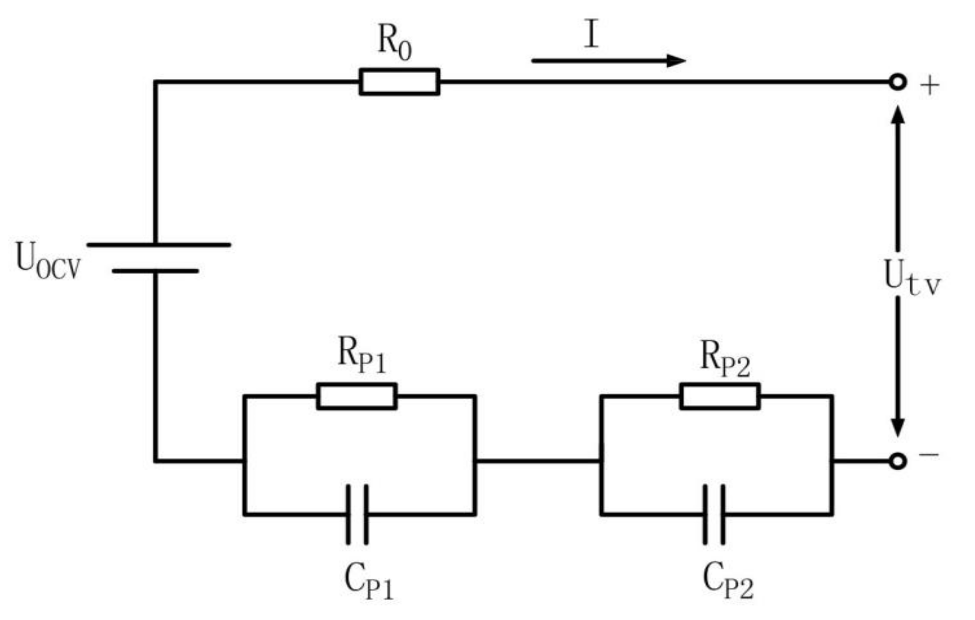
2.1. Battery Model

The circuit diagram for the DP model is shown in Figure 1. The current is positive in the discharge direction. U tv represents the terminal voltage and U ocv refers to the open circuit voltage, and its magnitude is only associated with the positive and negative electrodes of the battery and the electrolyte material. R 0 represents the ohmic resistance, which is composed of the physical and chemical resistance and contact impedance between the battery materials. The polarization resistance (Rp1, Rp2) and the polarization capacitance (Cp1, Cp2) are used to simulate electrochemical polarization and concentration polarization, respectively.
The relations of the DP model’s variables and parameters are expressed in Equations (1)–(3):
U t v = U O C V I R 0 U P 1 U P 2 U ^ P 1 = 1 C p 1 R p 1 U p 1 + 1 C p 1 I U ^ P 2 = 1 C p 2 R p 2 U p 2 + 1 C p 2 I
U P 1 k = U P 1 k 1 e T S τ 1 + I k R P 1 ( 1 e T S τ 1 ) U P 2 k = U P 2 k 1 e T S τ 2 + I k R P 2 ( 1 e T S τ 2 ) SOC k = SOC k 1 η T s C N I k
U tv ( k ) = U o c v I k R 0 U P 1 ( k ) U P 2 ( k )
where I k and U tv k are, respectively, the current values flowing through the battery and the terminal voltage values of the battery; U p 1 k and U p 2 k are the polarization voltages between the two polarization circuits at time k; τ 1 ,   τ 2 are the time constants of the polarization loop; TS is the sample time.

2.2. Model Parameter Identification

As shown in Figure 1, six parameters including the Open Circuit Voltage (OCV), R 0 , R P 1 , R P 2 , C P 1 , C P 2 need to be identified. In this paper, OCV was recognized from the pulse discharge experiments. For R 0 , R P 1 , R P 2 , C P 1 , C P 2 , the vector forgetting factor recursive least squares algorithm was employed for online identification.

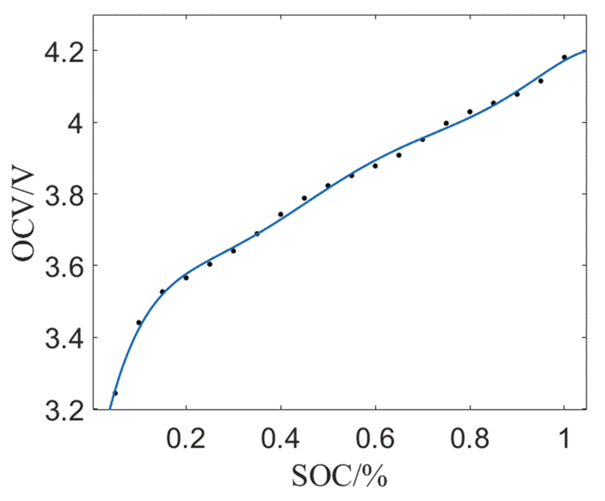
2.2.1. Identification of Open Circuit Voltage

The OCV is known as a nonlinear function of SOC. Since the accuracy of the OCV plays a crucial role in estimating SOC, it is necessary to acquire relationship between OCV and SOC of the battery. The pulse discharge experiments were designed to obtain the relationship between them and experimental procedures are as follows.
  • Charge the battery fully. At this time SOC = 1 and the measured battery voltage is recorded as OCV.
  • Discharge at 1 C until SOC = 0.95 and rest for 30 min. Measure the battery voltage and record it as the open circuit voltage of SOC = 0.95.
  • Step (2) is repeated until SOC = 0.05 and the battery voltage corresponding to each SOC is recorded.
Based on the experimental data, the fitted curve of SOC vs. OCV is obtained by using curve fitting tool in MATLAB. The result of fitting curves is shown in Figure 2, and the corresponding coefficients of the fitted sixth-order polynomial is presented in Equation (4) and the R-square from fitting is 0.9976.
U o c v = 29.81 · ( S O C ) 6 + 107.1 · ( S O C ) 5 150.6 · ( S O C ) 4 + 105.1 · ( S O C ) 3 38.04 · ( S O C ) 2 + 7.532 · S O C + 2.96

2.2.2. Parameter Identification with Vector Forgetting Factor Recursive Least Squares Algorithm

Other parameters including R 0 , R P 1 , R P 2 , C P 1 , C P 2 are identified using VRLS as follows.
Equation (2) is transformed into the following expression adapted to the least square method to estimate the battery parameter.
U t v = R P 1 R P 1 C P 1 s + 1 + R P 2 R P 2 C P 2 s + 1 + R 0 I + U o c v
Setting τ 1 = R P 1 C P 1 , τ 2 = R P 2 C P 2 , multiplying both sides of this equation by τ 1 s + 1 τ 2 s + 1 , we have:
τ 1 τ 2 U tv s 2 + τ 1 + τ 2 U t v s + U t v = τ 1 τ 2 R 0 I s 2 + R p 1 τ 2 + R p 2 τ 1 + R 0 τ 1 + τ 2 I s + R p 1 + R p 2 + R 0 I + τ 1 τ 2 U o c v s 2 + τ 1 + τ 2 U o c v s + U o c v
Setting a = τ 1 τ 2 , b = τ 1 + τ 2 , C = R P 1 + R P 2 + R 0 , d = R P 1 τ 2 + R P 2 τ 1 + R 0 τ 1 + τ 2 , we can obtain:
a U tv s 2 + b U tv s + U tv = a R 0 I s 2 + d I s + c I + a U o c v s 2 + b U o c v s + U o c v
Substituting s = h k h k Ts T ,   s 2 = h ( k 2 h k Ts + h k 2 Ts T 2 into Equation (7), we have Equation (8):
U t v k U o c v k = b T 2 a T 2 + b T + a U o c v k T S U t v k T S + a T 2 + b T + a U o c v k 2 T S U t v k 2 T S + c T 2 + d T + a R 0 T 2 + b T + a I k + d T 2 a R 0 T 2 + b T + a I k T S + a R 0 T 2 + b T + a I k 2 T S
where T represents the sampling time and T s refers to the interval of sampling time for parameter identification.
As a result:
U t v k U o c v k = k 1 U o c v k T S U t v k T S + k 2 U o c v k 2 T S U t v k 2 T S + k 3 I k + k 4 I k T S + k 5 I k 2 T S
where:
k 1 = b T 2 a T 2 + b T + a , k 2 = a T 2 + b T + a , k 3 = c T 2 + d T + a R 0 T 2 + b T + a , k 4 = d T 2 a R 0 T 2 + b T + a , k 5 = a R 0 T 2 + b T + a
The discrete equation of state at the time of (k-Ts), is:
U t v k T S U o c v k T S = k 1 U o c v k 2 T S U t v k 2 T S + k 2 U o c v k 3 T S U t v k 3 T S + k 3 I k T S + k 4 I k 2 T S + k 5 I k 3 T S
Subtracting Equation (11) from Equation (9), we can get:
Δ U t v k Δ U o c v k = k 1 Δ U o c v k T S Δ U t v k T S + k 2 Δ U o c v k 2 T S Δ U t v k 2 T S + k 3 Δ I k + k 4 Δ I k T S + k 5 Δ I k 2 T S
where TS = 4; Δ U tv = U tv k U tv k Ts ; the other expressions of Δ U 0 cv k , Δ I k in Equation (11) are obtained in a similar manner.
According to Equation (12), the regression equation of parameter identification of DP model can be transformed into:
y k = ω T k φ k + e k
where the corresponding parameter matrix is:
ω k = k 1 k 2 k 3 k 4 k 5 T φ k = Δ U o c v k T S Δ U t v k T S Δ U o c v k 2 T S Δ U t v k 2 T S Δ I k Δ I k T S Δ I k 2 T S T y k = Δ U t v k Δ U o c v k
The standard RLS is often utilized to the discrete system represented by Equation (13). However, if the change rate of the estimated parameter is different in the system discretization process, the application of the RLS algorithm is prone to failing. The tracking of the parameter’s change rate is easily impacted by the value of the forgetting factor. The parameters with a large change rate need to be matched with a smaller forgetting factor; the slowly changing parameters need a larger forgetting factor to track, so as to ensure that the RLS algorithm is stable in the tracking process of parameter changes. The change rate of parameters that need to be estimated are different in the lithium battery system. To obtain the best identification accuracy, the VRLS with multiple forgetting factors are utilized to estimate the parameters of the DP model. This paper uses λ w 1 , λ w 2 , λ w 3 , λ w 4 , λ w 5 , respectively, to denote the forgetting factors of the five parameters to be estimated in the parameter matrix w k , and calculates them with Equation (15). In this algorithm, these forgetting factors can be decoupled and adjusted to adapt to parameter changes to obtain the best estimation effect. The calculation formula of the forgetting factor in this paper is as follows:
λ ω i = λ 0 i λ 0 i λ 1 i exp t / τ i
where i = 1, 2, 3, 4, 5; λ w 1 , λ w 2 , λ w 3 , λ w 4 , λ w 5 , respectively, denote the calculation coefficients of the forgetting factor, and their corresponding values are shown in Table 1.
After solving the regression equation, the model parameters can be calculated as follows:
Setting K 0 = T 2 + bT + a , deducing Equation (10), we get:
k 0 = T 2 / k 1 + k 2 + 1 a = k 0 · k 2 b = k 0 k 1 + 2 k 2 / T c = k 0 k 3 + k 4 + k 5 / T 2 d = k 0 k 4 + 2 k 5 / T R 0 = k 5 / k 2
With a = τ 1 τ 2 , b = τ 1 + τ 2 , τ 2 b τ + a = 0 , solving the equation, we get:
τ 1 = b + b 2 4 a 2 ,   τ 2 = b b 2 4 a 2
Substituting into c = R p 1 + R p 2 + R 0 , d = R p 1 τ 1 + R p 2 τ 2 + R 0 τ 1 + τ 2 , we have:
R p 1 = τ 1 c + τ 2 R 0 d / τ 1 τ 2 R p 2 = c R p 1 R 0 C p 1 = τ 1 / R p 1 C p 2 = τ 2 / R p 2
The parameter identification process of the VRLS algorithm is presented in Table 2. In the VRLS algorithm, the sampling interval Ts has a crucial impact on the operation of the algorithm. If Ts is too large, the model estimation error will be large; if Ts is too small, it will affect the stability of the model. Therefore, Ts is taken as 4 to balance the precision and stability of the battery model.

3. Adaptive Cubature Kalman Filter Algorithm

Based on the third-order spherical radial cubature criterion, the Cubature Kalman filter predicts and updates the state of the nonlinear system through the linear cubature point. Synthesizing the third-order spherical radial criterion, Equation (19) is obtained:
R n f t N t ; t ¯ , P t d t = i = 1 N 1 2 n f n P t e i + t ¯ + f n P t e i + t ¯
where e i is the ith unit vector in the identity matrix.
The discretized state equation and observation equation estimated by SOC are shown in Equations (3) and (4), where state values x = U P 1   U P 2   SOC , system input values u k = I k , and system output values y k = U tv _ K _ . The application of ACKF for SOC estimation is summed up as follows:
(a). Initialize the state values X, error covariance values Px, process noise covariance Q, and measurement noise covariance R.
x ¯ 0 = E x 0 P 0 = E x 0 x ¯ 0 x 0 x ¯ 0 T
(b). Calculate the volume points and weights at the moment k 1 for the first time.
x k / k 1 _ R i = x k 1 + n P k 1 e i x k / k 1 _ R i + n = x k 1 n P k 1 e i i = 1 , 2 , n
w i = 1 2 n w i + n = 1 2 n
(c). Propagate the cubature points, namely, substitute the first calculated volume points into the equation of state.
x k / k 1 _ C i = f x k / k 1 _ R i , u k i = 1 , 2 , 2 n
(d). Calculate the state variable prediction and error covariance prediction:
x k / k 1 = i = 1 2 n w i x k / k 1 _ C i
P k / k 1 = i = 1 2 n w i x k / k 1 _ C i x k / k 1 x k / k 1 _ C i x k / k 1 T + Q k 1
(e). Calculate the cubature points and weights the second time.
x k _ R i = x k / k 1 + n P k / k 1 e i x k _ R i + n = x k / k 1 n P k / k 1 e i w i = w i + n = 1 2 n i = 1 , 2 , n
(f). Propagate the cubature points, namely, substitute the second calculated cubature points into the equation of state.
y k _ C i = g x k _ R i , u k i = 1 , 2 , 2 n
(g). Calculate the predicted value of the observed variables:
y k = i = 1 2 n w i y k _ C i
(h). Calculate the observation error covariance and cross-covariance:
P k y = i = 1 2 n w i y k _ C i y k y k _ C i y k T + R k
P k x y = i = 1 2 n w i x k _ R i x k / k 1 y k _ C i y k T
(i). Calculate the Kalman gain:
G k = P k x y · P k y 1
(j). Update the state value and error covariance:
x k = x k / k 1 + G k Y k y k
P k = P k / k 1 G k P k y G k T
(k). Adaptive update of QK and RK
The noise covariance is adjusted with battery voltage based on the residual sequence of the battery model. The modification and update expressions of QK and RK are shown in Equations (34) and (35).
Q k = G k F k G k T
R k = F k + i = 0 2 n w i y k _ C i Y k y k _ C i Y k T
Fk is the approximate estimate of the voltage residual covariance, which is expressed as:
F k = i = k L w + 1 k a i a i T
where a i is the voltage residual of the battery model, i.e., the difference between the calculated value of the voltage obtained at the cubature point of the second propagation and the actual terminal voltage; L w is the window size that matches the covariance.
Figure 3 shows the diagram of SOC estimation based on ACKF. After the initialization, it is necessary to measure the battery operating current and terminal voltage. Moreover, the predicted values of the state variables x k and the observed variables y k can be obtained through the update of time and measurement. The noise covariance is adjusted and corrected with the battery voltage based on the residual sequence of the battery model. Finally, one can calculate the errors on the basis of measured terminal voltage, then the battery SOC is estimated after correction and the algorithm goes to the next cycle.

4. Results and Discussion

In order to evaluate the performance of the present method based on VRLS online parameters identification and ACKF in SOC estimation, the UDDS and DST conditions are selected. The UDDS condition features rapid power changes and fierce current impact, whereas the DST condition is a complicated and variable power working condition that simulates the driving actions of a car, such as starting, acceleration, constant speed, braking, etc. It is easy to cause strong impact to the battery and SOC estimation is challenging under such complex conditions. The models of parameter identification and SOC estimation are implemented in the Simulink simulation environment in MATLAB.
Section 4.1 presents the setup of test bench. Section 4.2 shows the comparison of the two battery models tested. Comparison of two parameter identification methods is presented in Section 4.3. SOC estimation performance with different algorithms is evaluated in Section 4.4.

4.1. Experimental Setup

The experiment platform of battery test includes a charge–discharge test equipment (Xinwei BTS-5V300A), an upper computer, and a high and low temperature alternating heat and humidity test chamber (GDJS-150). This setup can simulate various battery charge and discharge patterns by loading the test program of the upper computer, execute the vehicle service condition, and obtain the data of battery voltage, capacity, power, and so on in real time. The sampling frequency is set to 10 Hz. The current loading accuracy is ±0.3 A, and the voltage loading accuracy is ±0.005 V, which is sufficient to guarantee the reliability of battery charge and discharge tests and data collection. The test chamber is capable of simulating the temperature and humidity range of the battery in the test process in a very high precision range. The control range for chamber temperature and humidity is −50~150 °C and 30–98% RH, respectively. The battery under investigation is connected to the channel of the test equipment through physical wiring, and is placed in the test chamber to ensure that the temperature and humidity of the battery become constant. The technical parameters of the tested ternary lithium battery are presented in Table 3.

4.2. Comparison of Two Battery Models

To compare the accuracy of the DP model and Thevenin model under UDDS and DST conditions [28], the DPVRLS and Thevenin-VRLS algorithms are utilized to identify battery parameters and the estimated values of terminal voltage obtained from the two battery models are compared with the experimental data. Figure 4 and Figure 5 show the terminal voltage comparison and error curves under UDDS and DST conditions, respectively.
Figure 4 and Figure 5 indicate that the agreement between the terminal voltage of DP-VRLS and the measured value is obviously better than that of Thevenin-VRLS, the maximal value of the error curve is smaller, and the volatility is gentler. The error value of DP-VRLS does not exceed 0.039 V, whereas the maximum error of Thevenin-VRLS is 0.061V [28]. This demonstrates that the two models realize satisfactory estimation performance, and the DP model has higher accuracy and better dynamic performance compared with the Thevenin model.

4.3. Comparison of Two Parameter Identification Methods

To prove the superiority of the online model identification over the offline model identification, the HPPC offline method and the VRLS online method are utilized to identify the DP model parameters. Figure 6 and Figure 7 show the terminal voltage curves under UDDS and DST conditions, respectively.
Figure 6 shows that the DP-offline method has large errors under the UDDS condition in general, and the maximum error of DP-offline is 0.4 V, while the maximum error of DP-VRLS is only 0.075 V. After the middle period of the discharge, the terminal voltage simulation curve starts to deviate from experimental data, especially in the later stage, which deviates from the measured value curve greatly and irregularly. The reason for this deviation is that when parameters are identified under the HPPC condition, to prevent the battery from over discharge, the experiment is stopped until the SOC is 5%. The relationships between parameters and SOC are fitted as sixth-order polynomial by using curve fitting tool in MATLAB based on the experimental data. The divergency begins at about 18,000 s in Figure 6, and the SOC is about 5% at this time. As the condition continues, there is a large error in parameter fitting because the fitting curve has a fitting error when the SOC is in the range of 0 to 5%. As the SOC approaches 0, the fitting error is large and the divergency becomes more pronounced.
In Figure 7, the curve of terminal voltage under DP-offline diverges from experimental data and the deviation becomes obvious in the later stage. One can see that the voltage of DP-VRLS is in agreement with the measured value steadily with the maximum error about 0.04 V, while the error of offline identification reaches 0.06 V and the error has increased by 50% compared to the former. This shows that the VRLS algorithm can effectively reduce the drawbacks of battery time-varying and instability in dynamic working conditions, and has strong advantages in parameter identification.
To further compare the models and the accuracy of online and offline estimation more thoroughly, the mathematical statistical results of estimation error are presented in Table 4. The maximum error, Mean Absolute Error (MAE) and Root Mean Square Error (RMSE) of the three algorithms under UDDS and DST conditions are calculated respectively; see Table 4. Under the DST conditions, the maximum error of DP-VRLS is 0.039 V, which is about 64% of the two algorithms, and the overall error range does not exceed 1.2% of the rated voltage. The maximum error of DP-VRLS under UDDS operating conditions is 0.0754 V, which is only 2.4% of the rated voltage. Its MAE and RMSE are smaller, indicating that the error fluctuation of DP-VRLS is smaller, the stability is better, and the dispersion is smaller. The statistical results show that the second-order DP model has higher accuracy and reflects the dynamic polarization effect of the battery better. The VRLS algorithm prevents the estimation drawbacks caused by the time-varying nonlinearity of the battery system and has reliable parameters identification accuracy. Both the battery model and the parameter identification method contribute to the accuracy of the model. The DP-VRLS algorithm integrates the battery model with the parameter identification well, and the proposed method of parameter identification is accurate and reliable.

4.4. Comparison of SOC Estimation with Different Algorithms

After identifying the model parameters, the SOC estimation performances based on ACKF are compared with that of EKF and CKF under UDDS and DST condition in this section. Figure 8 presents the SOC comparison curve among the estimates of three algorithms and the experimental measurement under UDDS conditions. Figure 8 shows that the SOC simulation value of ACKF algorithm and the measured value have the smallest deviation, and the divergence of EKF curve is the most obvious. In Figure 8b, as the working condition time is extended, the error accumulation of CKF and EKF continues to increase. In the middle and late period of the working condition, the three error curves are clearly differentiated, and the error of ACKF remains in a stable range. The error range of EKF is the largest and the maximum error is about 4%; the error of CKF is within 3%, and the maximum error of ACKF does not exceed 1.9%. This result shows that the ACKF algorithm realizes satisfactory dynamic estimation performance under complex working conditions.
Figure 9 presents the SOC estimation performance curves of ACKF, CKF, and EKF in DST condition. One can see that the SOC estimation curve of ACKF matches the measured value well, and the agreement is better than the other two algorithms. The error curve of EKF increases proportionally and CKF has a larger error than ACKF. The overall error curve of ACKF has the smallest fluctuation and the best stability, and the maximum error is around 0.015. In summary, the ACKF algorithm maintains an excellent estimation accuracy under DST condition.
Statistical methods can be used to more intuitively analyze the SOC error under UDDS and DST conditions. Table 5 shows the maximum error, MAE, RMSE of ACKF, CKF, and EKF algorithm, respectively: the maximum estimation error of the ACKF algorithm is 1.85%, and its MAE and RMSE are much smaller than the EKF and CKF algorithms. The ACKF algorithm has superiority in accuracy and stability. The error statistical parameters of the CKF algorithm are smaller than that of the EKF, and the cubature points are directly used for nonlinear propagation, which avoids the accumulation of linearization errors and enhances the accuracy of the algorithm. The maximum error of ACKF is 58% of CKF under the DST condition and 69% of CKF under the UDDS condition. In CKF, because the state and observation noise are constant, the error correction of SOC estimation is reduced. The ACKF algorithm adopts the module that tracks and corrects noise adaptively, which raises the accuracy and stability of the algorithm by reducing the interference of noise to the estimation result.

5. Conclusions

For the purpose of better SOC estimation performance, the parameters of DP model are identified online using the VRLS method. The ACKF model with online parameters identification is employed to estimate the SOC in UDDS and DST conditions. The research conclusion can be summarized as follows.
(1)
By comparing the estimated terminal voltage of the Thevenin model and DP model, we can conclude that on the one hand, the Thevenin model and DP model can be adopted to the dynamic and complex condition. On the other hand, the DP model has higher accuracy and better dynamic performance compared with the Thevenin model.
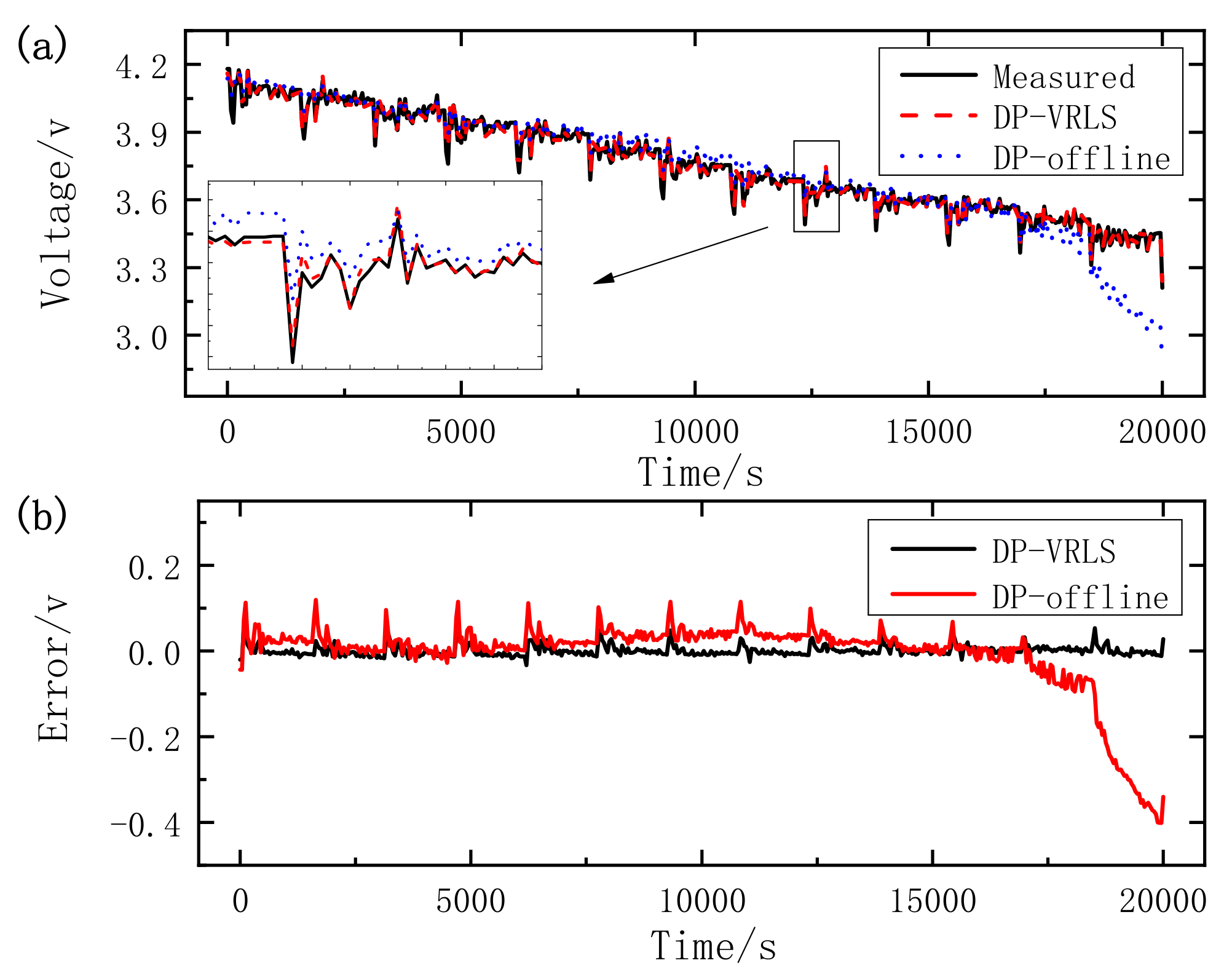
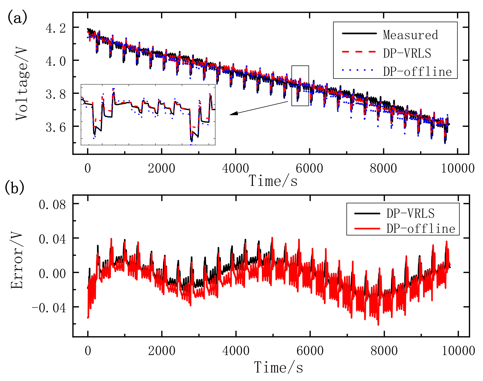
(2)
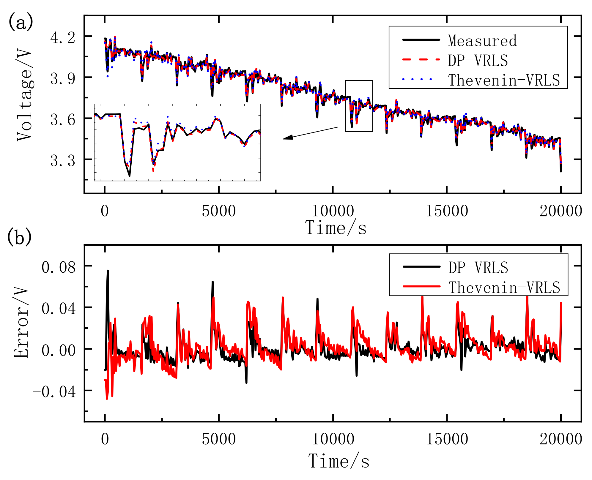
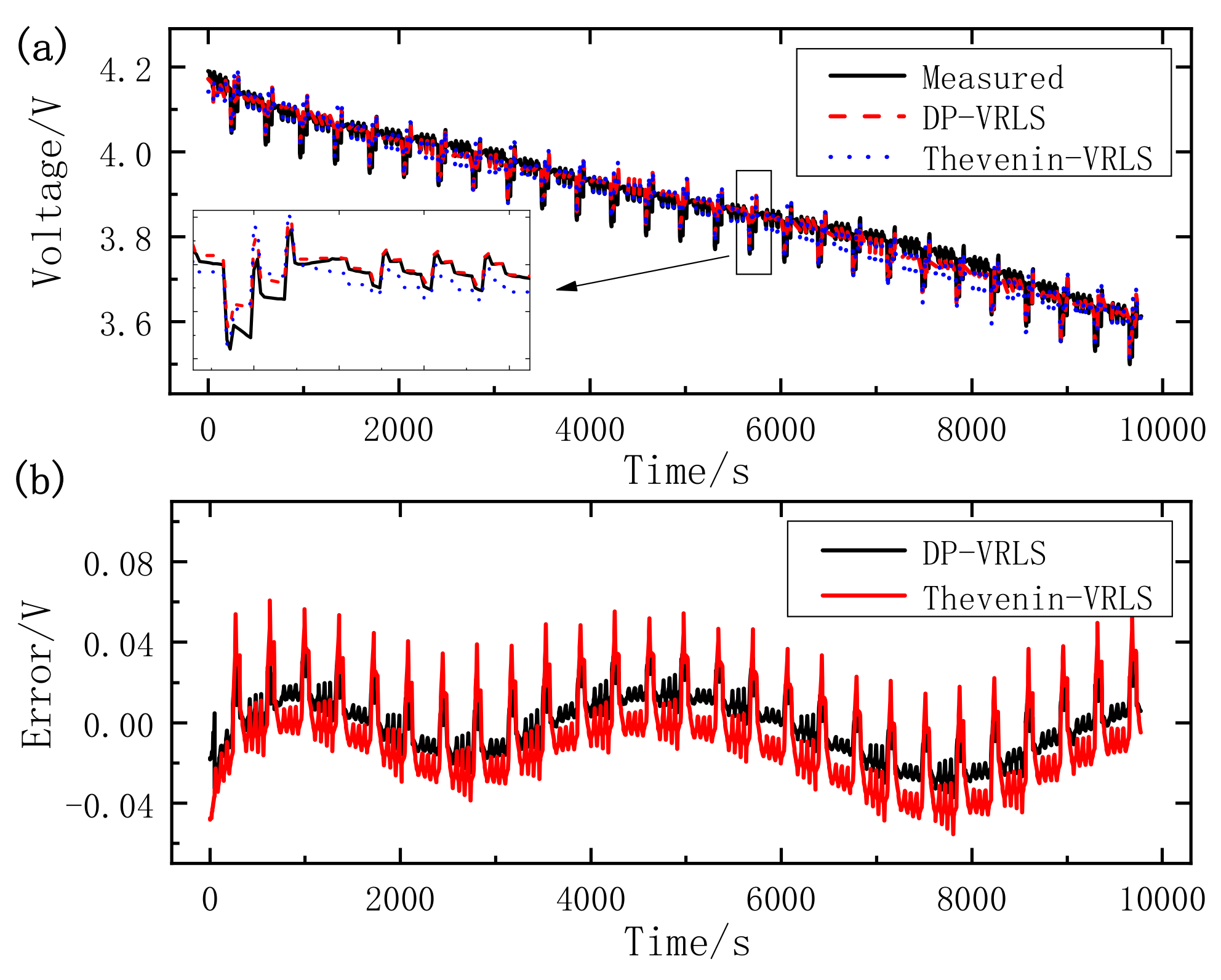
Online parameter identification based on VRLS has an improvement for voltage estimation over the offline parameter identification of the HPPC test, and it is shown that the proposed VRLS has a more accurate parameter identification ability.
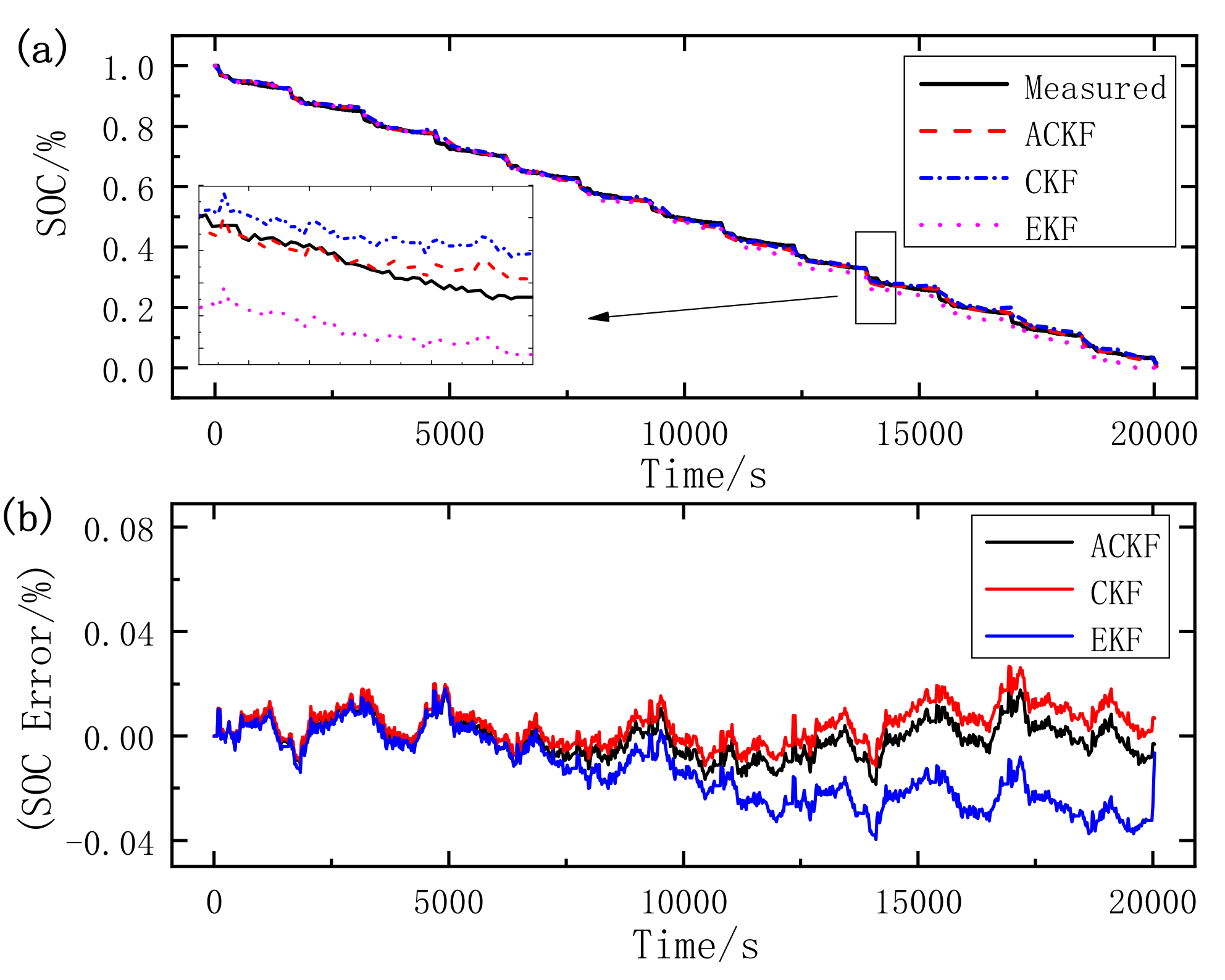
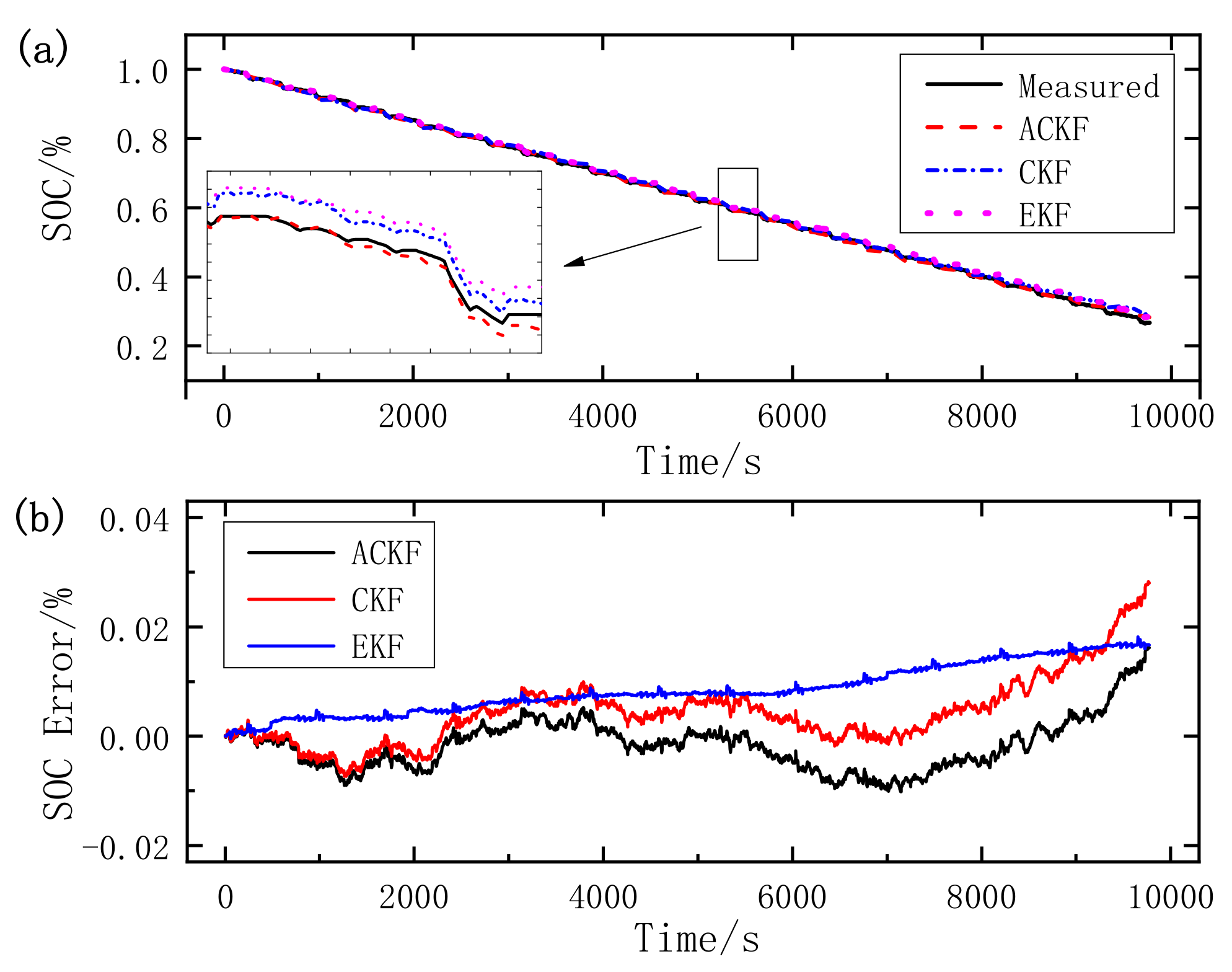
(3)
Experiments based on the two typical dynamic operating cycles are used to evaluate the superiority of the proposed algorithm compared with EKF and CKF in terms of accuracy and stability. The maximum errors of ACKF are 1.85% in UDDS and 1.64% in DST, the MAEs are 0.59% in UDDS and 0.39% in DST, and the RMSEs are 0.72% in UDDS and 0.49% in DST. The estimation accuracy is relatively high and the maximum error, MAE, RMSE of ACKF are all smaller than those of EKF and CKF. The results show that the ACKF has a satisfactory performance in SOC estimation, and has better accuracy and stability than EKF and CKF. To conclude, the VRLS-ACKF is capable of obtaining accurate SOC estimation and terminal voltage prediction with satisfying stability, which is suitable to implement in the real application. For future work, the proposed algorithm will be applied in BMS to verify its practicality.

Author Contributions

Conceptualization, W.L.; methodology, Y.T.; software, W.L.; validation, W.L.; formal analysis, Y.T.; investigation, X.C.; resources, M.L.; data curation, Y.T.; writing—original draft preparation, Y.T.; writing—review and editing, W.L. All authors have read and agreed to the published version of the manuscript.

Funding

This work was supported by the finance science and technology project of Hainan Province of China (No. ZDYF2020032).

Data Availability Statement

The data generated in this study cannot be shared.

Conflicts of Interest

The authors declare no conflict of interest.

Abbreviations

ACKFAdaptive cubature Kalman filter
AUKFAdaptive unscented Kalman filter
BMSBattery Management System
CKFCubature Kalman filter
DPDual polarization
DSTDynamic Stress Test
ECMsEquivalent circuit models
EKFExtended Kalman filter
EVSElectric vehicles
HPPCHybrid pulse power characterization
KFKalman filter
MAEMean Absolute Error
OCVOpen Circuit Voltage
PNGVPartnership for a New Generation of Vehicle
RLSRecursive least square
RMSERoot Mean Square Error
SOCState of charge
UKFUnscented Kalman filter
VRLSVector forgetting factor recursive least squares

References

  1. Cuma, M.U.; Koroglu, T. A comprehensive review on estimation strategies used in hybrid and battery electric vehicles. Renew. Sustain. Energy Rev. 2015, 42, 517–531. [Google Scholar] [CrossRef]
  2. Guo, X.; Xu, X.; Geng, J.; Hua, X.; Gao, Y.; Liu, Z. SOC Estimation with an Adaptive Unscented Kalman Filter Based on Model Parameter Optimization. Appl. Sci. 2019, 9, 4177. [Google Scholar] [CrossRef] [Green Version]
  3. Saw, L.H.; Ye, Y.; Tay, A.A.O. Integration issues of lithium-ion battery into electric vehicles battery pack. J. Clean. Prod. 2016, 113, 1032–1045. [Google Scholar] [CrossRef]
  4. Wu, Z.; Wang, G.; Xie, Z.; He, Y.; Lu, X. Lithium battery SOC estimation based on whale optimization algorithm and unscented Kalman filter. J. Renew. Sustain. Energy 2020, 12, 065501. [Google Scholar] [CrossRef]
  5. Zhang, R.; Xia, B.; Li, B.; Cao, L.; Lai, Y.; Zheng, W.; Wang, H.; Wang, W. State of the Art of Lithium-Ion Battery SOC Estimation for Electrical Vehicles. Energies 2018, 11, 1820. [Google Scholar] [CrossRef] [Green Version]
  6. Peng, N.; Zhang, S.; Guo, X.; Zhang, X. Online parameters identification and state of charge estimation for lithium-ion batteries using improved adaptive dual unscented Kalman filter. Int. J. Energy Res. 2021, 45, 975–990. [Google Scholar] [CrossRef]
  7. Hu, X.; Zou, C.; Zhang, C.; Li, Y. Technological Developments in Batteries: A Survey of Principal Roles, Types, and Management Needs. IEEE Power Energy Mag. 2017, 15, 20–31. [Google Scholar] [CrossRef]
  8. Farmann, A.; Waag, W.; Marongiu, A.; Sauer, D.U. Critical review of on-board capacity estimation techniques for lithium-ion batteries in electric and hybrid electric vehicles. J. Power Sources 2015, 281, 114–130. [Google Scholar] [CrossRef]
  9. Guo, X.; Kang, L.; Yao, Y.; Huang, Z.; Li, W. Joint Estimation of the Electric Vehicle Power Battery State of Charge Based on the Least Squares Method and the Kalman Filter Algorithm. Energies 2016, 9, 100. [Google Scholar] [CrossRef]
  10. She, C.; Wang, Z.; Sun, F.; Liu, P.; Zhang, L. Battery Aging Assessment for Real-World Electric Buses Based on Incremental Capacity Analysis and Radial Basis Function Neural Network. IEEE Trans. Ind. Inform. 2020, 16, 3345–3354. [Google Scholar] [CrossRef]
  11. Hannan, M.A.; Lipu, M.S.H.; Hussain, A.; Mohamed, A. A review of lithium-ion battery state of charge estimation and management system in electric vehicle applications: Challenges and recommendations. Renew. Sustain. Energy Rev. 2017, 78, 834–854. [Google Scholar] [CrossRef]
  12. Li, X.; Li, J.; Xu, L.; Ouyang, M.; Han, X.; Lu, L.; Lin, C. Online management of lithium-ion battery based on time-triggered controller area network for fuel-cell hybrid vehicle applications. J. Power Sources 2010, 195, 3338–3343. [Google Scholar] [CrossRef]
  13. Yang, N.; Zhang, X.; Li, G. State of charge estimation for pulse discharge of a LiFePO4 battery by a revised Ah counting. Electrochim. Acta 2015, 151, 63–71. [Google Scholar] [CrossRef]
  14. Huang, S.-J.; Huang, B.-G.; Pai, F.-S. An approach to measurements of electrical characteristics of lithium-ion battery with open-circuit voltage function. IET Power Electron. 2012, 5, 1968–1975. [Google Scholar] [CrossRef]
  15. Luzi, M.; Frattale Mascioli, F.M.; Paschero, M.; Rizzi, A. A White-Box Equivalent Neural Network Circuit Model for SoC Es-timation of Electrochemical Cells. IEEE Trans. Neural Netw. Learn. Syst. 2020, 31, 371–382. [Google Scholar] [CrossRef]
  16. Zhang, J.; Wei, Y.; Qi, H. State of charge estimation of LiFePO4 batteries based on online parameter identification. Appl. Math. Model. 2016, 40, 6040–6050. [Google Scholar] [CrossRef] [Green Version]
  17. Zhang, L.; Peng, H.; Ning, Z.; Mu, Z.; Sun, C. Comparative Research on RC Equivalent Circuit Models for Lithium-Ion Batteries of Electric Vehicles. Appl. Sci. 2017, 7, 1002. [Google Scholar] [CrossRef] [Green Version]
  18. Nejad, S.; Gladwin, D.T.; Stone, D.A. A systematic review of lumped-parameter equivalent circuit models for real-time esti-mation of lithium-ion battery states. J. Power Sources 2016, 316, 183–196. [Google Scholar] [CrossRef] [Green Version]
  19. Yang, F.; Li, W.; Li, C.; Miao, Q. State-of-charge estimation of lithium-ion batteries based on gated recurrent neural network. Energy 2019, 175, 66–75. [Google Scholar] [CrossRef]
  20. Chen, L.; Wang, Z.; Lu, Z.; Li, J.; Ji, B.; Wei, H.; Pan, H. A Novel State-of-Charge Estimation Method of Lithium-Ion Batteries Combining the Grey Model and Genetic Algorithms. IEEE Trans. Power Electron. 2018, 33, 8797–8807. [Google Scholar] [CrossRef] [Green Version]
  21. Luzi, M.; Paschero, M.; Rizzi, A.; Maiorino, E.; Frattale Mascioli, F.M. A Novel Neural Networks Ensemble Approach for Modeling Electrochemical Cells. IEEE Trans. Neural Netw. Learn. Syst. 2019, 30, 343–354. [Google Scholar] [CrossRef]
  22. Wang, K.; Feng, X.; Pang, J.; Ren, J.; Duan, C.; Li, L. State of Charge (SOC) Estimation of Lithium-ion Battery Based on Adaptive Square Root Unscented Kalman Filter. Int. J. Electrochem. Sci. 2020, 15, 9499–9516. [Google Scholar]
  23. Shuai, W.; Li, E.; Wang, H. An equivalent circuit model of a deformed Li-ion battery with parameter identification. Int. J. Energy Res. 2020, 44, 8372–8387. [Google Scholar] [CrossRef]
  24. Xia, B.; Chen, G.; Zhou, J.; Yang, Y.; Huang, R.; Wang, W.; Lai, Y.; Wang, M.; Wang, H. Online Parameter Identification and Joint Estimation of the State of Charge and the State of Health of Lithium-Ion Batteries Considering the Degree of Polarization. Energies 2019, 12, 2939. [Google Scholar] [CrossRef] [Green Version]
  25. Long, H.; Zhu, C.; Huang, B.; Piao, C.; Sun, Y. Model Parameters Online Identification and SOC Joint Estimation for Lithium-Ion Battery Based on a Composite Algorithm. J. Electr. Eng. Technol. 2019, 14, 1485–1493. [Google Scholar] [CrossRef]
  26. Xia, B.; Zheng, W.; Zhang, R.; Lao, Z.; Sun, Z. A Novel Observer for Lithium-Ion Battery State of Charge Estimation in Electric Vehicles Based on a Second-Order Equivalent Circuit Model. Energies 2017, 10, 1150. [Google Scholar] [CrossRef]
  27. Hu, X.; Li, S.; Peng, H. A comparative study of equivalent circuit models for Li-ion batteries. J. Power Sources 2012, 198, 359–367. [Google Scholar] [CrossRef]
  28. Wang, Q.; Wang, J.; Zhao, P.; Kang, J.; Yan, F.; Du, C. Correlation between the model accuracy and model-based SOC estimation. Electrochim. Acta 2017, 228, 146–159. [Google Scholar] [CrossRef]
  29. Groot, J.; Swierczynski, M.; Stan, A.I.; Kær, S.K. On the complex ageing characteristics of high-power LiFePO4/graphite battery cells cycled with high charge and discharge currents. J. Power Sources 2015, 286, 475–487. [Google Scholar] [CrossRef]
  30. Tan, Y.; Luo, M.; She, L.; Cui, X. Joint Estimation of Ternary Lithium-ion Battery State of Charge and State of Power Based on Dual Polarization Model. Int. J. Electrochem. Sci. 2020, 15, 1128–1147. [Google Scholar] [CrossRef]
  31. Sun, X.; Ji, J.; Ren, B.; Xie, C.; Yan, D. Adaptive Forgetting Factor Recursive Least Square Algorithm for Online Identification of Equivalent Circuit Model Parameters of a Lithium-Ion Battery. Energies 2019, 12, 2242. [Google Scholar] [CrossRef] [Green Version]
  32. Ren, B.; Xie, C.; Sun, X.; Zhang, Q.; Yan, D. Parameter identification of a lithium-ion battery based on the improved recursive least square algorithm. IET Power Electron. 2020, 13, 2531–2537. [Google Scholar] [CrossRef]
  33. Xiong, R.; Sun, F.; Chen, Z.; He, H. A data-driven multi-scale extended Kalman filtering based parameter and state estimation approach of lithium-ion polymer battery in electric vehicles. Appl. Energy 2014, 113, 463–476. [Google Scholar] [CrossRef]
  34. Partovibakhsh, M.; Liu, G. An Adaptive Unscented Kalman Filtering Approach for Online Estimation of Model Parameters and State-of-Charge of Lithium-Ion Batteries for Autonomous Mobile Robots. IEEE Trans. Control Syst. Technol. 2015, 23, 357–363. [Google Scholar] [CrossRef]
  35. Yu, Q.; Xiong, R.; Lin, C.; Shen, W.; Deng, J. Lithium-Ion Battery Parameters and State-of-Charge Joint Estimation Based on H-Infinity and Unscented Kalman Filters. IEEE Trans. Veh. Technol. 2017, 66, 8693–8701. [Google Scholar] [CrossRef]
  36. Xiong, R.; He, H.; Guo, H.; Ding, Y. Modeling for Lithium-Ion Battery used in Electric Vehicles. Proc. Eng. 2011, 15, 2869–2874. [Google Scholar] [CrossRef] [Green Version]
  37. Lao, Z.; Xia, B.; Wang, W.; Sun, W.; Lai, Y.; Wang, M. A Novel Method for Lithium-Ion Battery Online Parameter Identification Based on Variable Forgetting Factor Recursive Least Squares. Energies 2018, 11, 1358. [Google Scholar] [CrossRef] [Green Version]
  38. Zeng, Z.; Tian, J.; Li, D.; Tian, Y. An Online State of Charge Estimation Algorithm for Lithium-Ion Batteries Using an Improved Adaptive Cubature Kalman Filter. Energies 2018, 11, 59. [Google Scholar] [CrossRef] [Green Version]
  39. Ouyang, Q.; Chen, J.; Zheng, J. State-of-Charge Observer Design for Batteries With Online Model Parameter Identification: A Robust Approach. IEEE Trans. Power Electron. 2020, 35, 5820–5831. [Google Scholar] [CrossRef]
  40. He, Z.; Yang, Z.; Cui, X.; Li, E. A Method of State-of-Charge Estimation for EV Power Lithium-Ion Battery Using a Novel Adaptive Extended Kalman Filter. IEEE Trans. Veh. Technol. 2020, 69, 14618–14630. [Google Scholar] [CrossRef]
  41. Xia, B.; Lao, Z.; Zhang, R.; Tian, Y.; Chen, G.; Sun, Z.; Wang, W.; Sun, W.; Lai, Y.; Wang, M.; et al. Online Parameter Identification and State of Charge Estimation of Lithium-Ion Batteries Based on Forgetting Factor Recursive Least Squares and Nonlinear Kalman Filter. Energies 2018, 11, 3. [Google Scholar] [CrossRef] [Green Version]
  42. Yu, Q.; Xiong, R.; Lin, C. Online Estimation of State-of-charge Based on the H infinity and Unscented Kalman Filters for Lithium Ion Batteries. Energy Proc. 2017, 105, 2791–2796. [Google Scholar] [CrossRef]
  43. Wang, T.; Chen, S.; Ren, H.; Zhao, Y. Model-based unscented Kalman filter observer design for lithium-ion battery state of charge estimation. Int. J. Energy Res. 2018, 42, 1603–1614. [Google Scholar] [CrossRef]
  44. Arasaratnam, I.; Haykin, S.; Hurd, T.R. Cubature Kalman Filtering for Continuous-Discrete Systems: Theory and Simulations. IEEE Trans. Signal Process 2010, 58, 4977–4993. [Google Scholar] [CrossRef]
  45. Peng, J.; Luo, J.; He, H.; Lu, B. An improved state of charge estimation method based on cubature Kalman filter for lithium-ion batteries. Appl. Energy 2019, 253, 113520. [Google Scholar] [CrossRef]
  46. Xu, W.; Xu, J.; Yan, X. Lithium-ion battery state of charge and parameters joint estimation using cubature Kalman filter and particle filter. J. Power Electron. 2020, 20, 292–307. [Google Scholar] [CrossRef]
  47. Xiong, R.; Zhang, Y.; He, H.; Zhou, X.; Pecht, M.G. A Double-Scale, Particle-Filtering, Energy State Prediction Algorithm for Lithium-Ion Batteries. IEEE Trans. Ind. Electron. 2017, 65, 1526–1538. [Google Scholar] [CrossRef]
  48. Pei, Y.; Biswas, S.; Fussell, D.S.; Pingali, K. An elementary introduction to Kalman filtering. Commun. ACM 2019, 62, 122–133. [Google Scholar] [CrossRef] [Green Version]
  49. Claude, F.; Becherif, M.; Ramadan, H.S. Experimental validation for Li-ion battery modeling using Extended Kalman Filters. Int. J. Hydrogen Energy 2017, 42, 25509–25517. [Google Scholar] [CrossRef]
  50. Ouyang, Q.; Ma, R.; Wu, Z.; Xu, G.; Wang, Z. Adaptive Square-Root Unscented Kalman Filter-Based State-of-Charge Estimation for Lithium-Ion Batteries with Model Parameter Online Identification. Energies 2020, 13, 4968. [Google Scholar] [CrossRef]
  51. He, H.; Qin, H.; Sun, X.; Shui, Y. Comparison Study on the Battery SoC Estimation with EKF and UKF Algorithms. Energies 2013, 6, 5088–5100. [Google Scholar] [CrossRef]
  52. Arasaratnam, I.; Haykin, S. Cubature Kalman Filters. IEEE Trans. Autom. Control 2009, 54, 1254–1269. [Google Scholar] [CrossRef] [Green Version]
  53. Yang, H.; Sun, X.; An, Y.; Zhang, X.; Wei, T.; Ma, Y. Online parameters identification and state of charge estimation for lithium-ion capacitor based on improved Cubature Kalman filter. J. Energy Storage 2019, 24, 100810. [Google Scholar] [CrossRef]
Figure 1. DP model circuit diagram.
Wevj 12 00123 g001
Figure 2. OCV as a function of SOC.
Wevj 12 00123 g002
Figure 3. Diagram of SOC estimation based on ACKF.
Wevj 12 00123 g003
Figure 4. The estimated terminal voltages and corresponding errors based on different battery models under UDDS condition: (a) voltage comparison; (b) error of voltages.
Wevj 12 00123 g004
Figure 5. The estimated terminal voltages and corresponding errors based on different battery models under DST condition: (a) voltage comparison; (b) error of voltages.
Wevj 12 00123 g005
Figure 6. The estimated terminal voltage and corresponding errors based on different battery parameter identification under UDDS condition: (a) voltage comparison; (b) error of voltage.
Wevj 12 00123 g006
Figure 7. The estimated terminal voltage and corresponding errors based on different battery parameter identification under DST condition: (a) voltage comparison; (b) error of voltage.
Wevj 12 00123 g007
Figure 8. SOC simulation results in UDDS: (a) SOC; (b) SOC error.
Wevj 12 00123 g008
Figure 9. SOC simulation results in DST: (a) SOC; (b) SOC error.
Wevj 12 00123 g009
Table 1. Values for the calculation of forgetting factors λ w i .
iλ0iλ1iτi
10.9980.98500
20.9950.99500
30.990.97500
40.9980.98500
50.9950.99500
Table 2. Parameter identification process of VRLS algorithm.
Step 1. Initialize the parameters: ω 0 = E ω 0 , P 0 = E ω 0 ω ^ 0 ω 0 ω ^ 0 T
Step 2. Calculate the state variables and the predicted value of covariance matrix: ω ^ k = ω ^ + k 1   P k = P + k 1
Step 3. Update the gain: L ω k = P k φ k 1 + φ T k P k φ k 1
Step 4. Update the state variables and covariance matrix:
ω ^ + k = ω ^ k + L ω k y k ω ^ T k φ k P + k = Λ 1 E L ω k φ T k P k Λ 1
where Λ = d i a g λ w 1   λ w 2   λ w 3   λ w 4   λ w 5 , and E is a unit vector of the fifth order.
Table 3. Technical parameters of the battery.
ItemsParameters
Cathode materialsLiNi1-x-yCoxMnyO2
Nominal capacity (Ah)35
Rated voltage (V)3.7
Maximal continuous discharge current (C)3
Maximal pulse discharge current (C)5 (30 s)
Upper/lower cut-off voltage (V)4.2/2.5
Table 4. Error of terminal voltage estimation.
ConditionAlgorithmMaximum Error/VMAE/VRMSE/V
UDDSDP-VRLS0.07540.00870.0126
Thevenin-VRLS0.05250.01060.0149
DP-offline0.40140.04860.0907
DSTDP-VRLS0.03890.01230.0147
Thevenin-VRLS0.06060.01850.0227
DP-offline0.06120.01520.0192
Table 5. Errors of SOC estimation with different algorithms.
ConditionAlgorithmMaximum ErrorMAERMSE
UDDSACKF0.01850.00590.0072
CKF0.02680.00670.0084
EKF0.03990.01560.0188
DSTACKF0.01640.00390.0049
CKF0.02830.00560.0077
EKF0.01810.00850.0096
Publisher’s Note: MDPI stays neutral with regard to jurisdictional claims in published maps and institutional affiliations.

