Review

Characteristics of Battery Management Systems of Electric Vehicles with Consideration of the Active and Passive Cell Balancing Process

1
Faculty of Engineering, Islamic University of Medina, Medina 42351, Saudi Arabia
2
Electrical Engineering Department, University of Lahore, Lahore 54000, Pakistan
*
Author to whom correspondence should be addressed.
World Electr. Veh. J. 2021, 12(3), 120; https://doi.org/10.3390/wevj12030120
Submission received: 7 July 2021 / Revised: 9 August 2021 / Accepted: 10 August 2021 / Published: 13 August 2021

Abstract

:
Energy shortage and environmental pollution issues can be reduced considerably with the development and usage of electric vehicles (EVs). However, electric vehicle performance and battery lifespan depend on a suitable battery arrangement to meet the various battery performance demands. The safety, reliability, and efficiency of EVs largely depends on the constant monitoring of the batteries and management of battery packs. This work comprehensively reviews different aspects of battery management systems (BMS), i.e., architecture, functions, requirements, topologies, fundamentals of battery modeling, different battery models, issues/challenges, recommendations, and active and passive cell balancing approaches, etc., as compared to the existing works which normally discuss one or two aspects only. The work describes BMS functions, battery models and their comparisons in detail for an efficient operation of the battery pack. Similarly, the work presents a comprehensive overview of issues and challenges faced by BMS and also provides recommendations to address these challenges. Cell balancing is very important for the battery performance and in this work various cell balancing methodologies and their comparisons are also presented in detail. Modeling of a cell balancer is presented and a comparative study is also carried out for active and passive cell balance technique in MATLAB/Simulink with an eight cell battery packcell balancing approach. The result shows that the active cell balancing technique is more advantageous than passive balancing for electrical vehicles using lithium-ion batteries.

1. Introduction

In the advanced automobile era, an enormous move towards drive train modification is just around the corner. The development involves a complete shift from internal combustion engines (ICEs) to an electric drive train vehicles. The correlation that can be made to relate ICE drive trains to EV drive trains is that the gas tank is changed for a battery, an engine regulator replaces the fuel conveyance framework, and the propulsion center presently becomes an electric engine. This move is because of great headways in battery innovation, powerful hardware, and engine layout, which at last, society will comprehend. Another advantage of electric drivetrains over ICEs is that there is no requirement for a multi-speed transmission, meaning a more effective and extensive framework. The electric drive trains are gradually becoming less expensive, more rigid, and more minimal, with zero emission of harmful gases, while improving the vehicles’ range [1,2].
A portable source of electrical energy is required for EVs in order to fulfill the energy requirements and guarantee a reasonable autonomy. A battery is the force hotspot for the EV. Based on their charging ability, batteries can be divided into primary and secondary types. The primary type can be used only one time; however, the secondary type can be reused again by charging after being discharged. For the applications of EVs the secondary type with high energy density, long cycle life, smaller, light weight, small energy loss, and good safety level battery is required. Most commonly used batteries in EVs are lithium-ion (LIBs) lead acid, nickel-cadmium and nickel metal hydride, etc. Among these, LIBs are smaller in weight, highest energy, force densities, longer life cycle, better environmental performance, and high rate of charging and discharging as compared to other batteries. As battery is a critical part of the EVs, and its adequacy will essentially influence the vehicle’s security, financial matters, and dynamic execution, etc. Although LIBs are used in many handy electronic devices, however, it is still very challenging to use for EV applications due to the high power system requirements. Also, EV battery packs contain hundreds of times more cells than portable electronics. Therefore, in order to improve EV’s economy and safety, comprehension of the battery status from various battery conditions, for example, state of charge (SOC), temperature, current rate, charging, and releasing condition is significant. If the battery life is long, then the EV will be driven for longer time, i.e., it has higher efficiency [3,4].
Different properties of the batteries should be checked and controlled to maximizethe battery cells’ life and minimize expenses. Therefore, a battery management system (BMS) is essential for the management of LIBs to ensure the safe, durable, and reliable operation of EVs [1]. The complexity of a BMS depends on the application. In EVs, the BMS has to perform many complicated tasks as compared to other applications. Therefore, the lack of a suitable technical platform for the BMS still impeding the future development of EVs. The BMS must be able to cope with the complex nature of power batteries, such as high capacity, high power, wide temperature variation, and harsh driving conditions. Once mismanaged, the power battery may face extreme conditions, such as over-charge, over-discharge and over-heating, which may further induce fires or even explosions in serious more instances. Such stories are often reported all around the world. Therefore, advancing BMS to realize crucial tasks of safety management, high-efficient operation and reliable maintenance, is a huge challenge of the future EVs [5,6].
A literature survey shows that many papers have been written illustrating different aspects of BMS. However, the existing work normally discusses only one or two aspects of a BMS instead of providing a comprehensive analysis. Asan example, a few papers discuss only cell balancing approaches [7,8,9], a few papers discuss only BMS functionalities [10,11,12] a few papers discuss only issues and challenges and BMS topologies [13,14,15], a few papers discuss only different battery models of BMS [4,16,17], a few papers discuss other aspects of BMS [18,19,20], etc. However, this paper comprehensively discusses all aspects of BMS, i.e., functions/features, requirements, BMS topologies, fundamental of battery modeling, different battery models, issues/challenges, recommendations, cell balancing approaches, etc. Also, different parameters for battery modeling and modeling of a cell balancer are presented. Moreover, active and passive cell balancing techniques have also been simulated for an eight cell battery pack using MATLAB/Simulink.
The rest of the paper is structured as follows: Section 2 defines battery management systems. Section 3 presents the BMS functionalities and requirements. Section 4 presents BMS topologies. Section 5 presents the fundamentals of battery modeling and different battery models. Section 6 presents some issues and challenges. Section 7 presents recommendations. Section 8 presents a comparison among commercially available BMS. Section 9 presents active and passive cell balancing approaches. Section 10 presents battery modeling and our simulation for an eight cell battery pack for active and passive balancing. Section 11 presents the conclusions.

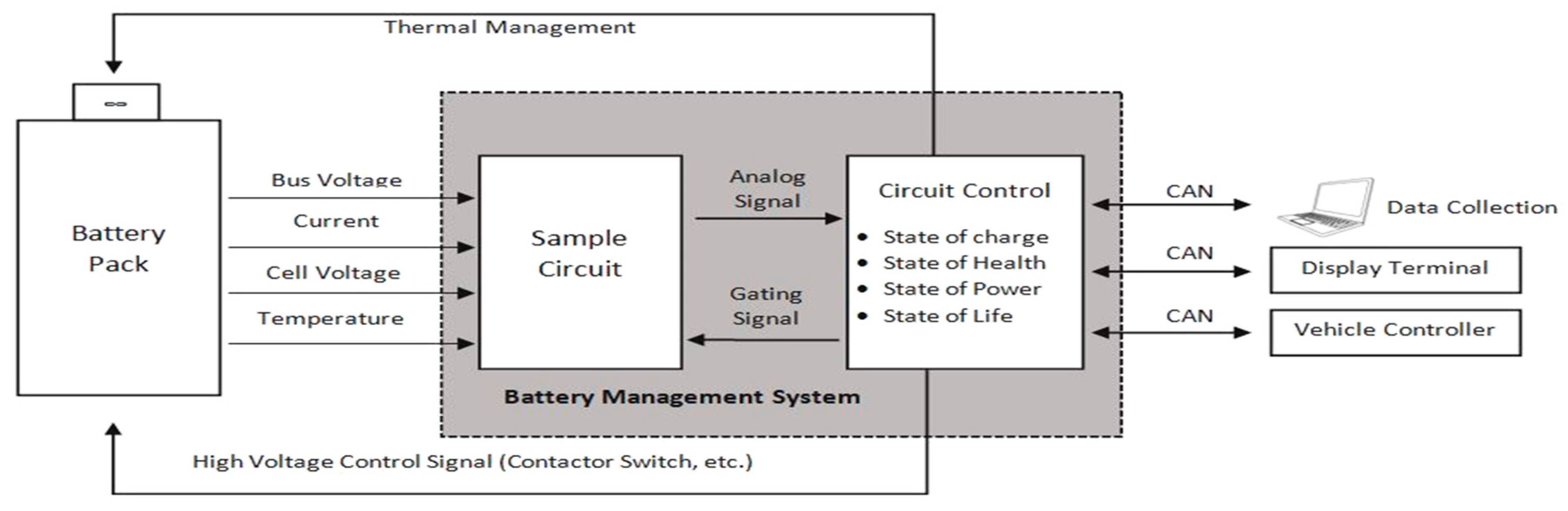
2. Batter Management System (BMS)

There are several cells in a battery bank connected in series or parallel, but every cell has its own characteristics that should be checked and controlled to upgrade the battery cells’ life and minimize expenses. Alongside the battery cells themselves, certain limits must be continued to get the most life from the cells. These limits include, for example, temperature limits, charging/discharging rate limits, release current cut-off points, and most extreme/least cell voltage limits. These requirements are observed, constrained, maintained, and administered by a framework that must be incorporated into a total battery pack. This framework is known as the battery management system (BMS) and is viewed as the battery pack’s mind. A compelling BMS will shield the battery from physical damage, estimate the battery life, manage the battery’s charging and discharging processes and the number of life cycles of the battery. The BMS’s fundamental duties are to screen the cell temperature, perform thermal management, arrange cell voltages, module or pack current, gauge SOC and SOH, and perform cell adjustments in order to avoid the speedy degradation of the battery. Thus, a vigorous BMS should provide better battery control, guarantee safe battery activity, and provide the most extreme required force and extend the battery life. A BMS must also communicate with other onboard systems, such as the engine controller, the temperature controller, the common bus bar, the monitoring system, and the car computer to maintain and perform different functions [4,21]. Figure 1 shows a general diagram of the battery management system [22].

BMS Architecture/Framework

Figure 2 [18] shows the hardware and software framework of a BMS. The BMS architecture can be split into hardware and software parts. The hardware components are embedded into the electric vehicle equipment to acquire different parameters of the batteries, i.e., voltage, current and temperature, etc. Simultaneous acquisition of the data should be done with a high sampling rate in order to improve the accuracy and to attain the desired monitoring capability without any error propagation. The software part is responsible of actively monitoring variables, managing alerts/protection, performing internal/external communication, performing different types of estimations (SOH, SOC, etc.) and balancing the battery cells, etc. [18]. The next section presents the BMS functions and requirements.

3. BMS Functions and Requirements

Designing BMS is a complex task to fulfill application’s specific requirements, system context, and manage battery cells. Figure 3 shows BMS functionalities for an efficient management performance, [18].
The next section presents details about the individual BMS functions.

3.1. BMS Features/Functions

BMS should be able to perform these features for an efficient system operation.

3.1.1. State of Charge Estimation (SOC)

SOC describes a battery’s remaining capability as a proportion to the total capacity under the same conditions. It can be considered equivalent to the fuel gauge in combustion engine vehicles. SOC estimation is very important to monitor and optimize the performance of the batteries by controlling their charging and discharging. Accurate SOC estimation can tell that how long an EV can drive before charging [3,4]. Generally, the useable capacity ranges from 100% to 5% SOC and the time taken to discharge a battery from 100 to 5% is defined as the runtime of the battery. The non-linear and non-stationary characteristics of the battery degrade its capacity over time and the BMS function is to keep the battery above a certain SOC by preventing it from discharging. The SOC cannot be estimated directly. If Ib (τ) is the charging current, then the charge delivered to the battery can be defined as t 0 t I b ( τ ) d τ . Then, SOC is given by the expression [20]:
SOC ( t ) = t 0 t I b ( τ ) d τ Q 0 · 100 %
where the capacity of the battery is defined as Q0 at time t [11,18,19,23]. It is very challenging to accurately estimate SOC by current methodologies. Generally, direct estimation (Coulomb counting, open circuit voltage (OCV)-based, etc.), model-based (equivalent circuit and electrochemical, etc.) and data driven-based approaches have all been used to calculate OCV for the online estimation of SOC. The precision of these models depends on the parameter tuning, training, state observers, and various practical conditions. However, all of these approaches have many limitations as described in [12,24]. Similarly, measuring SOC for a battery cell and for a battery pack is different and Table 1 presents this comparison for different methods [19].

3.1.2. State of Health (SOH)

SOH provides the health condition of the batteries, i.e., their degree of degradation. SOH is a function of the depth-of-charge. SOH estimation is complex and cannot be defined plainly like SOC. It basically represents that how many cycles are left before the battery will reach its end of life and can be represented as:
SOH = C u r r e n t   c a p a c i t y I n i t i a l   c a p a c i t y · 100
The SOH has also been defined in terms of parameters as
SOH ( t ) = SOH ( t 0 ) + τ = t 0 t δ f u n c ( I , T , SOC , o t h e r s ) d τ
where SOH (t0) is the initial battery health condition, δfunc is a function which depends on voltage, current, heat, SOC, mechanical vibrations and over-potential, etc. [11,18,19,23].
Pattipati [25] also combined capacity and power fade to represent the battery health condition. Capacity fade is the reduction in driving range and power fade is the reduction in acceleration capacity with respect to a fully charged battery. The deterioration of active material, increase in internal resistance and unalterable reactions generally affect battery health. SOH estimation is also a precondition for estimating the battery’s remaining useful life (RUL). BMS must be able to accurately assess the SOH of a battery for a safe and reliable operation. Generally, the SOH estimation is done by model-free, model-based, and data mining approaches [3,4]. Table 2 presents a comparison of different approaches for SOH assessment [12].

3.1.3. State of Life (SOL) or Remaining Useful Life (RUL)

SOL defines the remaining useful life, i.e., the remaining number of load cycles, etc., in which the battery can perform different functions accurately before reaching it send-of-life (EoL). Failures can be prevented and maintenances of the battery pack performed more accurately if the SOL prediction is accurate, especially for military applications. RUL prediction also enables BMS to reduce costs, increase accuracy, reliability, and avoid any kind of failure, etc. RUL is defined as:
RUL = Tf − Tc
Here Tf is a random failure of time and Tc represents current time. Pattipati also predicted RUL in terms of capacity fade C(i) and power fade P(i) as:
RUL ( k ) = { h ( P ( i ) ,   C ( i ) }
where i = 1   t o k . Different uncertainties, i.e., environmental conditions, modeling errors, etc., must be taken into account while predicting RUL [11,18,26].

3.1.4. State of Power (SOP)

State of power is another important parameter which should be monitored by the BMS. Every cell has different internal resistance which changes with time/usage, temperature, chemical properties and other environmental conditions as well. All of these parameters affect the power value of a cell. The SOP can be described by the following equation [27]:
SOP = P o w e r   ( c u r r e n t ) P o w e r   ( i n i t i a l )

3.1.5. State of Safety (SOS)

A BMS has to monitor/perform regularly for the safety of the overall system. It is very challenging to maintain a good state of safety as there is always a change in current, temperature, over/under voltage, over hearting, environmental conditions, etc. Therefore, a BMS should be able to perform efficiently to avoid any kind of failure in the system [28].

3.1.6. Depth of Discharge (DOD)

DOD defines the percentage of the battery capability which has been discharged with respect to the maximum capability. A discharge up to 80% is generally referred as a deep discharge. The life cycle of the battery gets shorter when the DOD is higher. For example, lead-acid batteries show less lifetime if the DOD is more than 50%. Therefore, the DOD should be monitored and maintained by BMS to avoid any unexpected situations. In order to achieve a longer life cycle, a larger battery with a lower DOD can be used during normal operations. The SOC is an alternative form of the same DOD measurement, and therefore, battery DOD can be defined as [12,28]:
DOD ( t ) = 1 SOC ( t ) = Q 0 0 t I b ( τ ) d τ Q 0 · 100 % .
The design of a BMS should make sure that that maximum energy content and delivery of full power can be achieved even with deep discharge for maximum usage.

3.1.7. State of Function (SOF)

State of function determines that how efficiently the battery can work/perform. It is estimated by the charge state, SOH, temperature data, charging/discharging data, and determines the capability of the battery to be matched with the system. The SOF can be described as [12]:
SOF = P P d e m a n d s P m a x P d e m a n d s
Here, P and Pmax is the power and maximum power which battery can supply and Pdemands is the current power demand.

3.1.8. State of Energy (SOE)

This parameter defines the ratio between remaining energy and maximum available energy of a battery and is given by the expression [27]:
SOE = E a c t u a l E m a x
An accurate SOE estimation by BMS is very important for energy optimization and management tasks such as range prediction, backup time estimation in stationary applications etc. Generally, temperature, charge/discharge current rate and aging affect the SOE and maximum available energy.

3.1.9. End of Life (EOL)

EOL refers to the time when a battery will stop working and the time remaining to reach that limit is called RUL. At EOL, the overall system becomes unreliable. However, there is an increase in prediction accuracy at EOL and also a gradual decrease in predication variance. EOL is generally assumed when the battery capacity is reduced by 75–80% of its rated capacity value and should be estimated accurately by BMS [18].

3.1.10. End of Discharge (EOD)

EOD refers to the stage when SOC is 0% and the battery is empty. It is due to the energy loss and reduction in battery voltage. The battery is out of charge when it has no more power. BMS should be able to assess the battery conditions regularly and should avoid EOD situations [18].

3.1.11. Thermal Management

Another critical function of BMS is to keep the battery pack temperature within defined limits. LIBs’ performance, i.e., battery capacity, life, energy conversion/usage efficiency, reliability, and safety, etc., are affected by both high and low temperatures. Similarly, severe environmental conditions can also cause a thermal runaway which may make the battery explode. Also, the type, number and optimal placement of contactors, sensors, fuses, or electric bus bars (which may carry the battery pack’s main current) is very important to ensure safe thermal management. If thermal sensors are not placed in optimal places, misreading and thermal blind spots can result. Different ways are used to keep the temperature within limits [3,14]. For an example, the Tesla BMS uses liquid cooling (a tube is passed through the battery pack) to keep the cell temperature within certain limits [29].

Internal Temperature Estimation

Measuring the internal temperature of the battery is more difficult task as compared to measuring the surface temperature as sometimes there is more than a 12 °C temperature difference. However, measuring the internal temperature makes BMS capable of saving energy, avoid fires/explosions and understanding aging effects more accurately. Measuring the internal temperature by using micro temperature sensors is generally complex and costly. Model-based approaches measure the internal temperature more accurately, but parameter tuning and the acquisition of other internal information are key issues in all these approaches [4,30].

3.1.12. Voltage Measurement

Voltage measurements are another important task which a BMS should perform precisely. A BMS must have at least one voltage acquisition channel for each cell to acquire the current voltage level. Usually, front-end chips of BMS have an accuracy of 1 mV and a range of 12 to 16 bits, i.e., resolution of about 380 μV. SOC estimation also depends heavily on voltage measurements. Therefore, algorithms which do not depend too much on voltage measurement accuracy should be used [14].

3.1.13. Current Measurement

Accurate current measurement is also critical for accurate SOC estimation by the BMS. The Coulomb counting method is generally used to measure the current and to assess dynamic SOC. However, due to the certain drift, offset, and temperature errors of current sensors this method does not provide precise SOC measurements. Current sensors in EVs should measure currents ranging from from milliamperes to 1000 Amperes and should also be able to capture fast current changes. Current sensors should also have good immunity against EMI noise and small offsets, especially for low current measurements [14,31].

3.1.14. Cell Monitoring and Cell Balancing

Cell monitoring is one of the most important tasks of a BMS. A battery pack may have hundreds of LIBs which may behave differently during the run-time. BMS should continuously monitor the cells’ conditions which will ultimately help in managing, protecting, equalizing and controlling the operations, etc. [20]. It will also help in charging/discharging control, temperature control, communication, fault finding and assessment, etc. Similarly, cell balancing is the most crucial task of a BMS. A BMS has to try to maintain an equal state of charge in each cell. Figure 4 shows the impact of SOC imbalance during charging and discharging scenarios, [32,33].

3.1.15. Power Management Control

Another important function of a BMS is to reduce the power consumption and minimize losses. The performance of batteries will be rapidly destroyed without a proper power management control. Therefore, in case of unstable power supply and for any unusual operation power management control techniques should be applied by the BMS for a safe, stable, and efficient operation [34].

3.1.16. Charging and Discharging of Cells

Charging and discharging of cells should be carefully monitored by BMS as the efficiency, durability, and life cycle of LIB depends on its charging and discharging. Memory effect is removed by proficient charging and discharging and improves battery discharging period. The operating window of the LIB is around 2.5–4.2 V and the BMS should make sure that the battery is always operated within safe limits [35].

3.1.17. Communication

The BMS has to maintain simultaneous bi-direction (internal and external) communications with whole system, i.e., power electronics, vehicle control unit, etc., to provide status updates, send/receive commands and perform other functions in real time. The central control unit uses internal communications to connect with the internal hardware. External communications are done between the BMS and other high-level hardware such as computers or HMI through wirelessly or wire-connected devices. External communications can be achieved by serial communications, CAN bus communications, DC bus serial communications, etc. BMS has to maintain the speed and reliability during communication in order to meet the minimum requirements of any process [10,14].

3.1.18. Computation

A BMS system has to perform many functions, i.e., data collection, data processing, charging/discharging current, maintain charging/discharging limit, state estimations, etc. Therefore, the BMS must be very fast, dynamic, efficient and accurate to perform all these functions correctly. A BMS should have accuracy as high as ±0.2 m or at least an accuracy of 1–2 mV [10,36].

3.1.19. Data Monitoring and Storage

BMS should be effectively able to monitor different parameters, i.e., output current/voltage, charging status, notifications, etc. Otherwise, the BMS will not be able to perform many functions and evaluate the state of the battery accurately. Similarly, in order to store and evaluate different kinds of available data, BMS should have good data storage. BMS should be able to utilize the stored data to perform different functions and predict any unexpected hazard in order to enhance safety, performance and function of EV [10,14].

3.1.20. Miscellaneous BMS Functions

In addition to the prescribed functions, a BMS must also be able to perform different miscellaneous functions such as reducing non-recurring cost linked with the design and validation of the BMS; decrease the development time of systems and batteries; promote standardized interfaces for cross-compatibility of batteries and equipment which are expected to reduce recurring costs; decrease the burden on the user; increase safety; identify errors in the system; management of regenerative energy; be able to accurately predict the maximum battery capacity for safe and reliable operations, etc. [37].The next section presents BMS requirements to perform different functions efficiently.

3.2. BMS Requirements

3.2.1. Electromagnetic Interference (EMI)

Sensors are vulnerable to the EMI making readings faulty and in a worst case scenario make the data completely useless although detectable. Therefore, every electric and electronic component and other loads should be designed keeping in mind EMI. In order to reduce EMI effects, measures should be taken as defined in the ISO7637-1 standard, i.e., using common mode chokes and blocking capacitors [14,38].

3.2.2. Contactors Requirement

Battery poles need to be galvanically disconnected in a battery pack. This can be achieved by using contactors which are also used to disconnect large DC currents in case of any failure. The switch off performance of the system may also be reduced by a large amount if disconnecting and extinguishing the electric arc on the contactors’ blades is not done properly in the case of DC currents [14]. Similarly, switch off efficiency can be reduced by a large amount if magnetic arc extinguishers are not used to push the arc away from the contact blades. Similarly, switch-on action of the blades poses another hazardous. While closing, blades will bounce and on every bounce an electric arc will happen making the blades hot. At the end of bouncing very hot blades will be pushed and may weld with each other. In order to avoid all these hazards, zero potential across the contactors should be maintained by a special circuit, pre-charge unit should be established, and zero switching power should be ensured during any switching action [10,14].

3.2.3. Redundancy

The cost, design process time limitation, and other factors make it difficult to achieve a high degree of redundancy in a BMS. However, the ISO 26262 standard demands redundancy of the system in order to enhance the reliability. The standard demands that there should be at least two different chips to acquire cell voltages accurately and BMS should select the most trustworthy signal from these two different sources [14,39]. Similarly, redundancy should exist in BMS for other functions such as higher level of processing in central processing units, protection approaches, memory error correction and self-test mechanism implementation, etc.

3.2.4. Galvanic Isolation

High and low voltages sections in a battery pack should be galvanically isolated in order to decouple digital signals by optical, inductive or capacitive means. Similarly, thermal sensors should be galvanically isolated to avoid any faults in high voltage sections from low voltage sections. Moreover, galvanic isolation must also be provided in a BMS between the battery pack and the vehicle electric control unit (ECU) [14,39].

3.2.5. Overall Protection

As LIBs can explode, a BMS should also make sure to provide protection to its all components against over- and undercurrent/voltage, overheating/pressure, leakage current/voltage, short circuits, over charging/discharging, faults in connected devices, ground faults, system or command failures, etc. The protection circuit in a BMS should be efficient and should also be designed keeping in mind the type, size, battery or cell used, connected device, purpose of use, etc. [40].

3.2.6. Other Requirements

Depending on the application, many new requirements and constraints, i.e., space and system costs, etc.) can arise which should be satisfied by the BMS. For an example, mechanical robustness, weight and power consumption are particularly important parameters for aerospace applications [41]. The next section presents different BMS topologies.

4. BMS Topologies

BMS topologies define the communication architecture, connection of batteries, control structure, cost, installation complexity, maintenance, and reliability, etc., of the system. The BMS topologies are described as below.

4.1. Centralized Topology

In this approach, a single master module is used which is connected to the batteries serially providing single cell voltage, current, and other measurements. This topology is cheap, requires less maintenance and provides good accuracy. However, long cabling, possibility of mixing up or incorrect connections of the inputs increase the risk of short circuits and other miscellaneous errors. Also, the scalability and flexibility of the whole architecture is limited as the maximum number of batteries is strictly predefined. Moreover, if the master controller fails then whole system will fail, undermining the reliability severely [3,42]. In real life, the Volkswagen e-Up (2014) model used a BMS centralized topology with a battery pack containing 17 serially connected modules [14].

4.2. Modularized Topology

In this approach, several identical modules are connected to the individual batteries similar to the centralized BMS topology. One of the modules works as a master module which controls the entire battery pack, while the other modules acquire information from the batteries and send it to the master module. This topology provides improved flexibility and scalability. The scalability can be increased by simply adding another BMS module. The features of the BMS can also be deployed in individual modules. However, the overall cost of this topology is high and the number of inputs is still fixed. This topology also needs more hardware and programming effort. However, the entire system is not affected if there is a breakdown of one module as in case of centralized BMS. The Tesla Model-S and Mitsubishi Motors use a modular BMS topology [3,14,42].

4.3. Distributed Topology

In this topology, a BMS module is assigned to each cell. The BMS controller handles the overall measurements and communication. This topology is reliable, robust, and cost-efficient. This approach is more flexible and scalable as compared to centralized and modularized approaches. The cells can be added or removed increasing the flexibility and scalability. Moreover, high measurement accuracy is achieved due to short connecting wires and better interference immunity. However, this topology is complex and costly [3,42].

4.4. Decentralized Topology

In this topology, many equal decentralized BMSs units provide the entire functionality locally, reliably, and autonomously. There is no chance of entire system failure due to the absence of a central control unit. This topology is flexible and scalable and the inputs can be added or removed even after installation. The scalability also increases with rising decentralization. This approach offers many advantages, but the development requires new methods [3,42]. Table 3 summarizes the comparison among various BMS topologies [42].
The next section presents the fundamentals of battery modeling and different battery models.

5. Battery Modeling

5.1. Fundamentals of Battery Modeling

This section provides a brief idea regarding the different behavior exhibited by the battery.

5.1.1. Usage-Capacity and State of Health (SOH)

These features have already been described in Section 3.1.1 and Section 3.1.2.

5.1.2. Polarizations

During the substance responses in batteries, bothersome impedance emerges. These unfortunate impedances are generally known as polarization. The reactions happen in steps and initiation polarization happens due to slowest step. The dispersion also influences response rate among reactants and items because of focus contrasts called fixation polarization. The electronic opposition of dynamic mass and current gatherers, ionic obstruction of electrolytes, and the contact opposition between dynamic mass and current authorities all add to Ohmic polarization. Misfortunes coming about because of these polarizations are considered by protections Rtrans, L, R-series, and Rtrans_S. All polarizations are answerable for mishaps commonly known as I2R mishaps. The mishap builds increases the temperature of the battery which can be represented as:
T e m p r i s e = I 2 R · R t h e r m a l
where Rthermal is the thermal resistance [12,20,23].

5.1.3. Charge Recovery Effect

The battery recuperation impact misuses a shrouded event occurring inside the battery. When the pace of outside action is quicker, for example, when the battery energy is released at a high rate, the pace of synthetic responses inside the battery can’t keep up with it. Thus, the convergence of the dynamic charges close to the anodes turns out to be not exactly their location in side the battery. When the battery has a low burden or no load for quite a while, dynamic charges have sufficient opportunity to diffuse to the anodes, and charge recuperation happens. Subsequently, the usable limit of the battery released at a high rate is lower than that of one released at a low rate [12,20,23].

5.1.4. Utilization Factor

This is generally known as battery effectiveness and is typically communicated as Coulomb proficiency, vitality productivity, or voltage productivity. Vitality effectiveness is an umbrella term that considers both voltage and Coulomb proficiency. The capacity of the battery is influenced by the vitality lost. Accordingly, the capacity diminishes as the normal release current increments. This infers the battery release work is a super-straight capacity of the normal release current [43]. In general energy efficiency is defined as:
E n e r g y   e f f i c i e n c y = O u t p u t   e n e r g y I n p u t   e n e r g y · 100
where output energy is the discharge energy and input energy is the energy required to charge to the initial state. The efficiency of the battery is affected by the energy lost (I2R), which means that the efficiency decreases, as the average discharge current increases [20,23]. The next section presents different battery models.

5.2. Battery Models

Building a proper battery model is very important for the BMS design, functionality, control and optimization. Figure 5 presents different battery models.

5.2.1. Battery Electric Model

Electrochemical model, reduced-order model, equivalent circuit model and data-driven model are the main battery electric models [4]. Electrochemical models are mainly characterized by battery’s strength, physical aspects, stress, and current. These models are able to represent the electrochemical process within the battery accurately. However, it is difficult to represent many parameters in real time such as chemical composition, etc. These models also have large computational overheads due to the involvement of many partial differential equations [4,18]. Reduced-order models can be approximated from full order electrochemical models by suitable assumptions with some loss of information. In this way, the computational overhead is reduced and desired parameters can be identified in real time applications. In equivalent circuit models, the battery is abstracted as an electric circuit, i.e., Rint model, Thevenin model, etc., and the dynamic characteristics are represented by algorithms. As external features are used to model the battery, therefore, most of the internal information is lost. This approach is simple and widely used in real time applications as less parameters are required [44]. This approach also shows good performance for low SOC range and provides accurate temperature distribution prediction. Data-driven models depict the relation between the input and output signals of batteries, i.e., battery electric behaviors without any prior knowledge. Comprehensive test data of the battery operation range should be available with efficient tuning for better model accuracy and good generalization ability. The data-based models can be generally categorized as machine learning, filtering, and stochastic [3,4,18,45].

5.2.2. Battery Thermal Model

The heat generation model, heat transfer model, reduced-order thermal model and data-driven model are the thermal models used to acquire batteries’ thermal characteristics. Heat generation models generally use activation, concentration and Ohmic losses to represent heat generation. There are three popular approaches which have been used widely in real time applications, as presented in [4].
Battery heat transfer uses heat convection, heat conduction and heat radiation to get the thermal behaviors of the batteries. High-heat hot spots can be detected by three-dimensional approaches while one dimensional heat transfer models can only capture thermal information along one direction. Many reduced-order thermal models have also been designed to maintain battery thermal management. In one of the approaches, the order of a LIB model is reduced to low-order linear model from a one-dimensional model and results show that the reduced model accurately predicts the temperature [3,4,45].

5.2.3. Battery-Coupled Electro-Thermal Model

Strong coupling exists between a battery’s electric and thermal behaviors. In order to acquire battery electric behaviors (e.g., current, voltage) and thermal behaviors (e.g., surface/internal temperature) simultaneously, several coupled electro-thermal models have been designed such as coupled lump parameter and coupled distributed-parameter models. In one of the approaches, a 3-D electro-thermal model was developed to approximate battery states and measure heat production. In another approach, a coupled 3-D electro-thermal model was designed to examine the effect on battery temperature due to other battery operations such as coolant flow-rate and discharge current, etc. [4]. Similarly, hybrid and empirical approaches have been used for battery modeling. In empirical simulations (statistical models), experimental cell data is used to simulate the battery behavior under similar conditions. These models do not provide any details about the battery characteristics and match only the data without considering the physical or chemical concepts which is feasible for real-time systems [4,18,45]. Table 4 presents different battery models with their advantages and disadvantages [3,4,12,18,46,47].
BMS have many challenges which are described in the next section.

6. Issues and Challenges of BMS

6.1. SOC Estimation Issues

SOC estimation is very critical, however, estimating SOC accurately is very challenging due to the high nonlinearity characteristics of EVs. Coulomb counting is one of the easiest approaches, but it has many issues such as initial SOC errors, current measurement and integration errors, uncertainty about battery capacity, timing oscillator errors, etc. Similarly, the open circuit voltage (OCV) approach cannot be used in real time as the battery needs to rest before the OCV can be measured, i.e., due to the relaxing effect, etc. [13]. Similarly, errors in the parameter estimation, voltage and current measurement errors, effects of aging and temperature are other issues with the OCV approach. Similarly, the electrochemical impedance spectroscopy (EIS) approach requires a longer time and is costly. Therefore, the existing approaches have many challenges and SOC estimation under realistic conditions has not been broadly done. The most difficult job is to estimate SOC by using a low cost BMS which should have small memory storage, but fast speed [11,18,19,23].

6.2. Real-Time SOH Estimation Issues

Real time SOH estimation is an open challenge as current approaches do not estimate battery health precisely. Existing model-based approaches have many limitations and do not predict the health status accurately. Similarly, data driven approaches have issues such as different training and machine learning methods. Therefore, the available options are to replace the battery prematurely impacting financial burden to owner and too much waste in the environment or wait for a complete failure which enhances the safety issues [13,18,19,23].

6.3. Optimal Charging Problem

Battery charging techniques are less efficient, less safe, and take lot of time as compared to refueling combustion engine cars. Constant trickle current is the common method for charging, but it uses low current which takes long charging time. By increasing charging current the time to charge a battery can be decreased, but it may increase the battery OCV above than safety threshold and also generate heat [13,48]. Traditional battery charging approaches have many limitations as shown in Table 5 [4].
Therefore, battery charging is a challenging task to maintain a balance between charging efficiency, heat, lifespan, and battery deterioration.

6.4. Fast Characterization

SOC and SOH are two important offline characteristics required in a BMS, but it is very time consuming and real time estimations have many issues. For real time SOC estimations by simple OCV-SOC models reduces accuracy, accumulates different errors from other estimated parameters, etc. These OCV models also cover the estimated SOC range depending on the battery usage pattern and do not cover the entire SOC range which can only be achieved by a complete charge/discharge profile. Similarly, SOH characterization is almost impossible in real-time [13,49].

6.5. Existing Battery Models Issues

Generally, physical methods (equivalent models, electrochemical models, etc.), data driven methods, and hybrid methods are used to characterize batteries in a BMS. However, these models have many issues as presented in Table 4. For physical approaches, exact conditions are required for the conduction of different tests which is not possible in different environments. Data driven methods have higher computational complexity and performance depends on the test data and training approaches. Although many new intelligent techniques/algorithms have been developed for efficient BMS, these approaches also have many challenges [4,13,18,19,23].

6.6. Data Abundance, Variety, and Integrity Issues

Data abundance and data variety are the main challenges in executing intelligent algorithms in battery models as the accuracy of these approaches depends on these factors. However, it takes a lot of time to collect a large amount of diverse data which also increases the computational complexity and leads to over-fitting issues due to the training time extension [50]. Similarly, data integrity is another issue as the existing data base has a permanent charge/discharge pattern and temperature conditions used in a laboratory environment. Moreover, battery test benches used in laboratories suffer from equipment precision, noise impact, and electromagnetic interference issues, etc. Therefore, BMS evaluation under various changing conditions is needed in real world environments [46,50].

6.7. Parameter Selection Issues for Intelligent Algorithms

The efficiency of intelligent algorithms depends on their input features, framework, training approaches, and hyper parameter adjustment. Designing a suitable structure and appropriate selection of hyper parameters for intelligent algorithms is a difficult task which may also cause data under fitting and over fitting issues. The existing trial and error approaches for the selection of hyper parameters suffers loss of human energy and takes a lot of time [50].

6.8. Optimization Issues for Intelligent Algorithms

The integration of intelligent methods and different control schemes needs optimization, but it has many challenges as optimization algorithms have different convergence speed, execution time, and complexity. Therefore, the selection of suitable optimization technique is needed for intelligent algorithms [50].

6.9. Thermal Management Issues

Measurement of local and distributed temperature information is required by BMS for accurate measurement of SOC and RUL and to avoid any failure, etc. Although, different approaches are used, low cost, accurate, and high range temperature sensors are required for a smart BMS, especially for internal temperature measurement [3].

6.10. Thermal Runaway

This is an irreversible chemical process initiated by the increase of SOC, high number of aging cycles, overcharging a single cell voltage above the standard voltage (4.35 V), and increasing number of charge/discharge cycles, etc. It can cause lithium plating, overcharging, short circuiting, heat generation processes, etc. Fast charging also increases the possibility of thermal runaways, further enhancing the danger of explosion [3,4].

6.11. RUL Prediction Issues

Predicting RUL accurately by BMS has also many challenges due to modeling insufficiencies, system noise, and degraded sensing fidelity, etc. RUL predication based on aging mechanisms has many uncertainties and is limited to certain types of batteries. Predicting RUL using data-driven approaches suffers from the health indicator inaccuracy and hybrid methods suffer from the complexity and computational issues [3,4,8].

6.12. Early Charge Termination Issues

Early charge termination may reduce the LIBs capacity, i.e., raising internal impedance and resulting in long operations, etc. During charging, the safety functions may abort charging if any of the serially connected cells reaches its over-voltage limit (4.35 V) to avoid overloading. Due to this, the battery pack may be severely undercharged and useful life may be reduced [6,32].

6.13. Premature Cells Degradation Due to Overcharging

If any cell in a battery pack has less capacity than other serially connected cells in a pack and if they start at the same SOC then cell imbalance will happen. A defined voltage will be achieved by the pack, but every cell voltage will be different. If the capacity deficiency of lower cell is more than 10% then this cell’s voltage will start rising into a dangerous area resulting in cell degradation or a safety issue. Therefore, cell degradation processes can be considered as auto accelerating and is very challenging to handle this issue in a BMS [6,24].

6.14. Early Discharge Termination & Over-Discharging Issues

Capacity reduction of the batteries may also happen if early discharge termination (if any cells in a pack reached low voltage threshold earlier) is done to avoid over-discharging/damage of any other cell. The cell-based termination voltage is generally less than the pack-based threshold voltage. Low cells are bypassed at the end of discharge phase to increase the cell’s useful discharge time. However, to implement efficient bypassing technique is expensive in a BMS. Similarly, over discharging may also reduce cell capacity due to different chemical reactions and may cause a detonation [6,17,33].

6.15. Issues of Safe Operating Region & Continuous Efficient Operation

A safe operating region cannot be defined for batteries due to continuous change in internal and external environment conditions. This may create unreliability and instability within cells posing serious issues. Also, it is always difficult to ensure a continuous proficient operational state, especially for peripheral control units of the BMS as different factors affect the electrochemical properties of the batteries [44,51].

6.16. Memory Effect Issues

Memory effect happens due to recharging many times after being partially discharged or many charge-discharge cycles during normal operation. This effect decreases the memory holding capacity of battery and might produce cell imbalances [38].

6.17. Aging Issues

Internal resistance and capacitance fading mainly cause aging of the battery. Similarly, high temperatures also accelerate the aging process. It is hard to monitor the aging process until a sudden change in battery performance happens. An appropriate model which particularly takes into account cell aging parameters must be designed to overcome this issue [15].

6.18. Hysteresis Characteristics Issues

With this phenomenon, battery SOC has a higher value during charging than discharging, and therefore, the SOC-OCV curve is not consistent with the charge and discharge making it difficult to estimate SOC. The concentration and electrochemical polarization, dissipation of energy and ohmic resistance cause hysteresis characteristics [52].

6.19. Existing BMS Not Universal

Every BMS has its own features, i.e., different cell balancing and communication methods. Therefore, there is an issue of non-interchangeability of software and hardware among different BMSs. The existing BMS are also not universal in many other aspects, i.e., this restricts battery selection, results algorithm selections, and restricts reusing battery packs for energy storage for other BMS, etc. [14,52].

6.20. Self Evaluation Issues

BMS assessment is a very difficult since it is very hard to represent many complex features, i.e., power and capacity fade, thermal effects on different parameters, and relaxation effects, etc., of LIBs. Therefore, the BMS evaluation and validation under different failure conditions needs to be analyzed to find efficient solutions. Particularly, real-time self-evaluation needs to be designed further in the presence of gradual and rapid temperature changes as compared to the constant temperature settings used in laboratories [13].

6.21. Estimation of Maximum Capacity and Modeling under Different Conditions

Currently, a full discharge test of a battery is employed for capacity estimation and it is calculated on-line as c a p a c i t y =   I d t . The capacity will be higher with longer integration time and maximum capacity can be achieved if it is discharged at a constant rate. However, the battery discharge rate is not constant and it will not be fully discharged every time. Similarly, battery modeling under different conditions or under combined factors instead of a single factor is still subject to query [13,53].

6.22. Capacity and Power Fading Issues

During discharge, transformations of the active materials of the battery occur which increases the capacity loss. Similarly, an increase in internal impedance and voltage drop may affect the power rate. Both of these phenomena increase the SOC error [22,48,53].

6.23. Safety Issues & Handling of Potential Risks

Every cell behaves differently during cycling which may cause cell imbalance triggering a safety hazard. The performance of the LIBs also gets deteriorated by external environmental conditions, temperature changes and unseen factors, etc. Battery deterioration may cause leakage, insulation breaks, and short-circuits. Serious situations, i.e., spontaneous combustion and explosions, etc., and some unprecedented risks might occur such as exothermic reaction of lithium ions with oxygen if LIBs are opened in air, or exothermic reactions producing hydrogen gas if exposed to water, etc. These reactions can be very dangerous. Moreover, presence of highly reactive chemicals close to each other makes batteries inherently dangerous. Fires or explosions can happen if overheating/overcharging happens. The cathode can be decomposed if the maximum voltage is exceeded producing high heat and increasing short circuit risks. Decomposition of the electrolyte can also happen if voltages are extremely high, which is very dangerous [54,55].

6.24. Battery Recycling Issues

Recycling of batteries is another issue which needs to be taken care. The number of used LIBs is increasing rapidly, which demands a good mechanism of collection and recycling of the batteries. This will reduce environmental problems and will also increase the recycling potential. However, there is no clearly defined process which will have minimum environmental effects [3,13].

6.25. Battery Reuse Issues

Battery reuse is another challenge for BMS. BMS algorithms heavily depend on the characterizations of batteries carried out in laboratories which are effective only one time. As the electrochemical properties of the batteries changes with usage and environmental conditions, it will be not safe to use the old batteries again under the assumption of similar characteristics. The batteries have also valuable metals such as copper, aluminum, and cobalt, etc. Therefore, if we can use these batteries again, it will be very beneficial as the increased mining of the metals used in these batteries is also creating shortage of these metals along with increases in prices [13,16].

6.26. Battery Disposal Issues

Some used batteries are classified as hazardous waste which needs to be disposed of properly. If these LIBs are not disposed of properly it may cause explosions, environmental issues, and safety hazards. It may also lead to expensive clean-up. There are regulatory issues while disposing of batteries, along with related transportation, treatment, and disposal costs.

6.27. Batteries Discharging Issues

Discharging of batteries is required when damaged/used cells cannot be opened safely but discharging of these batteries may create a safety hazard. If the batteries are discharged in brine, hydrogen and oxygen gases will be produced which must be ventilated to avoid a detonation. Similarly, current must be kept low to avoid overheating if resistors are used to discharge the batteries [13].

6.28. Battery Charger Issue

Universal battery chargers are another issue for BMS. Custom battery chargers are generally smaller and used only for household applications and may also produce extreme electronic clutter and environmental waste. Therefore, the battery charger designers have to address this issue due to the different types of batteries used [13,45,49,56].

6.29. Self-Discharge & Different Charging/Discharging Rate Issues

SOC estimation is also affected by battery self-discharge which is basically a loss of charge. Self-discharge may happen due to the ambient temperature, effect of diffusion process, cycle times and storage time. Similarly, SOC estimation is also affected by different charge/discharge rate. Higher discharge rates also enhance the depth of interaction, but it is very important to operate the battery within acceptable limits to enhance the battery life and to prevent overcharge/over-discharge [57].

6.30. Communication Issues with Chargers

A BMS has to communicate with internal vehicle components, the charger and external devices. A well-diverse controlled area network bus is used for internal communication. Communication with the charger is done through the system management bus (SMBus) which provides battery current condition and usage history to the charger. However, because of the many different manufacturers and battery types it is hard to design a uniform communication with the charger [13].

6.31. BMS Power Source and Power Consumption Issues

Batteries are the only power source in EVs and the BMS takes power from the same battery which it is supposed to protect and maintain. This increases the difficulty of the design of the BMS. Similarly, BMS consume power all the time whether the car is running, idle or charging. Therefore, a BMS must consume very little power when the car is not charged for a long times (eventually the car may be cranked or charged before its next use) to avoid battery drainage. This problem is still very common even with popular cars like the Tesla [13,25].

6.32. Miscellaneous Issues

BMS have many other miscellaneous issues such as data logging functions are very important for establishing a database to store the driving patterns and other useful information of the EVs. However, there is usually very limited data logging function availability in a BMS; the BMS circuitry is still complex, costly and bulky, consumes high power, and pressure management is difficult. A smart BMS is needed for advanced EV applications; SOC estimation of LIB pack is very hard. LIB pack SOC imbalance affects power, energy computation and safety system [45]; Prognostics are not as efficient as diagnostics as less work has been done on the evaluation and comparing performances of different kinds of prognosis; A compact battery testing system (BTS) is needed to test the batteries instead of individual modules from different manufacturers which also increase error for different measurements, etc. [17,35,43]. The next section describes some recommendations to overcome the existing issues/challenges.

7. Recommendations

7.1. Enhancing Safety and Reliability of BMS

The main hazards of LIBs are exposure to high voltage, arcing, fires, vented gas combustibility and vented gas toxicity, etc. Interlock circuits and insulation monitoring should be used to enhance safety and reliability of the batteries by maintaining proper distances between PCBs inside batteries and connectors. Digital isolator ICs should be used for galvanic signal isolation instead of optocouplers for superior performance and reliability. Sensors should be placed inside battery pack to reduce the risk of fire. Similarly, contactors should be used for disconnecting battery pack from system along with melting fuses. Software errors and sensor faults should be taken care by the use of knowledge of electrical behavior of the battery. It should make sure that any safety action may not trigger any other safety hazard and the safety and reliability are always balancing each other. Current interrupt devices and positive temperature coefficient approaches should be used in LIBS for further safety. Gas sensors can also be a cost-efficient way to enhance the safety of BMS. All BMS units must follow the most stringent safety standards as defined by the ISO26262 standard [18,24,38,45].

7.2. Development of New Battery Models/Approaches

New models/approaches should be developed to address the current issues related to battery states estimations, cell balancing, optimal charging, fast characterization, RUL, real time impedance estimation, and so on as the existing models (electric/thermal, data driven, etc.) have many limitations. New methods should be highly efficient and cost effective [22,38].

7.3. Advanced Multi Scale and Co-Estimation Process Needed

SOC and SOE change rapidly with current variation while the SOH and RUL vary with capacity fluctuation. Therefore, multi-scale and co-estimations processes should be developed by using different spatial and temporal scales for estimating battery states more accurately. It will also reduce the computation of BMS. Similarly, optimizing the data-driven control strategy with multi-scale multi-dimension approaches may be more efficient for multi-scale state joint estimation [6].

7.4. Algorithm Hybridization

Optimization of hybridized intelligent algorithms has shown advantages over single intelligent algorithms in recent studies. However, the complexity and unwanted outcomes have also increased. Therefore, more research should be done to develop efficient hybrid algorithms [50].

7.5. Development of Advanced Prognostic Approaches

Advanced prognostics and health management (PHM) approaches should be developed to monitor different parameters, i.e., temperatures, rate of charge and discharge, DOD, vibrations, etc. It will help to estimate the system’s state of health in advance and suitable decisions/actions can be applied by BMS to further improve the safety, reliability and life of the system [53].

7.6. Efficient Prototype Design and Training Performance Enhancement

Highly efficient and reliable BMS with small memory and high speed should be developed for the implementation of intelligent methods and other approaches to estimates battery states and for fault diagnosis. Similarly, time and training accuracy are the major challenges while executing intelligent methods, especially deep learning algorithms. More research is required for selecting appropriate parameters and training algorithms to speed up the training procedure.

7.7. Advanced Thermal Management Approaches

Further study should be done to find new ways to keep the battery temperature at an optimal level. Electrochemical impedance spectroscopy and sensorless temperature detection methods should be used for enhanced accuracy and safety. Similarly, new technologies should be developed to measure the internal temperature more accurately. Use of external battery thermal management systems approaches, i.e., air/liquid cooling and material cooling, etc., can also be considered [58].

7.8. Understanding Aging Effect

Understanding the effect of aging on different parameters of LIBs is very important for a BMS to accurately predict SOH. Battery aging dynamics are multifaceted, entangled, and alike which make it very difficult to estimate aging. New methods should be developed to understand this effect.

7.9. Life Cycle Assessment

Further research must be done to find out new material and their effect on the lifecycle patterns of batteries. Those materials which are uncommon, expensive, poisonous, and hard to recycle should not be used in the manufacturing of LIBs. If model simulations show that battery pack life is extended with the use of newly found materials without affecting the performance at steady state. Then it will really attract the battery manufacturers and will also reduce the recycling load and disposal infrastructure [45,47].

7.10. Fast Charging Requirement

Fast charging is the urgent need of EVs development. Batteries undergoing fast charging require more sophisticated battery management system and much more accurate estimations of conditions in order to prevent overcharging and overheating. Therefore, BMS should have an optimal charging strategy which should be less time-consuming, highly efficient, safe, and based on optimal solutions.

7.11. Enhancing LIBs Capacity

The capacity of the LIB is influenced by many unseen factors, i.e., vibrations, environmental factors, operating conditions, and engineering variations, etc. Current technologies and prognostics are not able to accurately predict the degradation resulting from all this. Therefore, new technologies should be developed to enhance the real lifetime of the LIBs. Abnormality detection approaches and different driving patterns should be used to update the predictive results and to develop more efficient battery models.

7.12. Uniform Rules Required for Disposing of Used LIBs

There are different regulations all over the world regarding disposing of used LIBs. However, uniform and universal rules should be made to handle this issue without posing any environmental impact and for further scientific research and industrial practices.

7.13. Efficient Recycling

Used batteries have still useful energy. For an example, a Tesla Roadster battery consists of 6831 cells and it will be a massive waste problem if there were no recycling. New technologies should be developed by government and non-governmental agencies to find out different economical and most beneficial ways to extract these useful energy/resources from used batteries [13].

7.14. Efficient Reuse

Research should also be done that how to reuse batteries in order to save the remaining energy. These approaches should be efficient and environment friendly. It will also save the rare battery resources inside the Earth.

7.15. Universal BMS

Adaptive strategies should be developed to build a universal and open source BMS. This will enable different BMS manufacturers to collaborate for the enhancement and development of hardware and software’s and will also improve the overall efficiency of BMS. It will also enable integration of third part functionalities easily which will make BMS cost effective and to meet future requirements.

7.16. Wireless BMS

Wireless BMS should be used to improve performance and to meet societal changes. It will reduce the cost, size, weight and will increase the efficiency of BMS by avoiding large amount of wiring in existing BMS. The existing wiring is costly, prone to mechanical failure, and makes it hard and time consuming to fix/replace any component. Wireless BMS will improve vehicle efficiency, reduce cost, and extend driving range along with offering more accurate and useful information about the condition of the battery cells [58].

7.17. Integration of BMS with Big Data Platform

The precision of intelligent algorithms can be more improved through cloud storage, cloud computing and big data platforms in real-world environments. Cloud BMS and the digital twin technology could also be potential solutions for limited data logging functions and computational issues. Moreover, intelligent methods can be trained under real-time tests and can be more accurate [59].

7.18. BMS Virtualization

BMS master control unit should be replaced by a virtual machine which should run directly on vehicle control unit (ECU). It will reduce cost, complexity and space of overall BMS system as monitoring and measurement will be dedicated to slave modules only. For an example, this virtual machine can be monitored by real time systems such as PikeOS from SYSGO [27].

7.19. BMS Structure Enhancement

Two electrodes of the batteries must be separated by a non-flammable and solid barrier made of insulation material to avoid any contact of electrodes, even in case of an accident. Similarly, retardants with a higher flashpoint than electrolytes should be used to prevent fires. Moreover, fuel, oxidizer, and control unit must be chosen in such a way that the battery is not exposed to fire or any abnormality during a combustion process [55].

7.20. BMS Installations Recommendations

The equipment rating and marking instruction must be strictly followed. The compatibility of new equipment must be checked in case of any replacement. Third-party verification is recommended to ensure safety in order to avoid manufacturer and design faults. It is always recommended to remove whole battery bank instead of few batteries. A safety logbook should be maintained with regular safety checks of BMS to fulfill any requirements and modifications [54].

7.21. Tamper Proof BMS and Shutdown/Reset on Abnormal Behavior

BMS must be tamper proof and must be highly sensitive to any kinds of tampering either to hardware or software for safe operation of BMS. Similarly, BMS must be able to shutdown/reset and disconnect electrical connection to load/charger in case of any abnormal behavior/readings avoiding any safety issue.

7.22. Misc Recommendations

There are many other recommendations such as all BMS units must be separated physically so that any abnormal issue within a BMS unit should not spread to other units; There should be more than a minimum number of nominally identical equipment to act as backup in case of any failure; Different battery testing systems (BTSs) such as Digatron, Arbin BT 2000, DAQ and NEWARE BTS 4000, etc., are used for battery testing. However, an advanced and universal battery testing system should be developed to avoid different equipment errors; Very less work has been done for the SOC estimation of battery packs. Further work is required in this area; others existing issues such as cell balancing, self-discharge, and estimation of maximum capacity, hysterics issues, and rate of charge/discharge issue must be taken care with advanced technologies/models [9,24,41,49]. The next section presents a comparison among commercially available BMS.

8. Commercially Available BMS
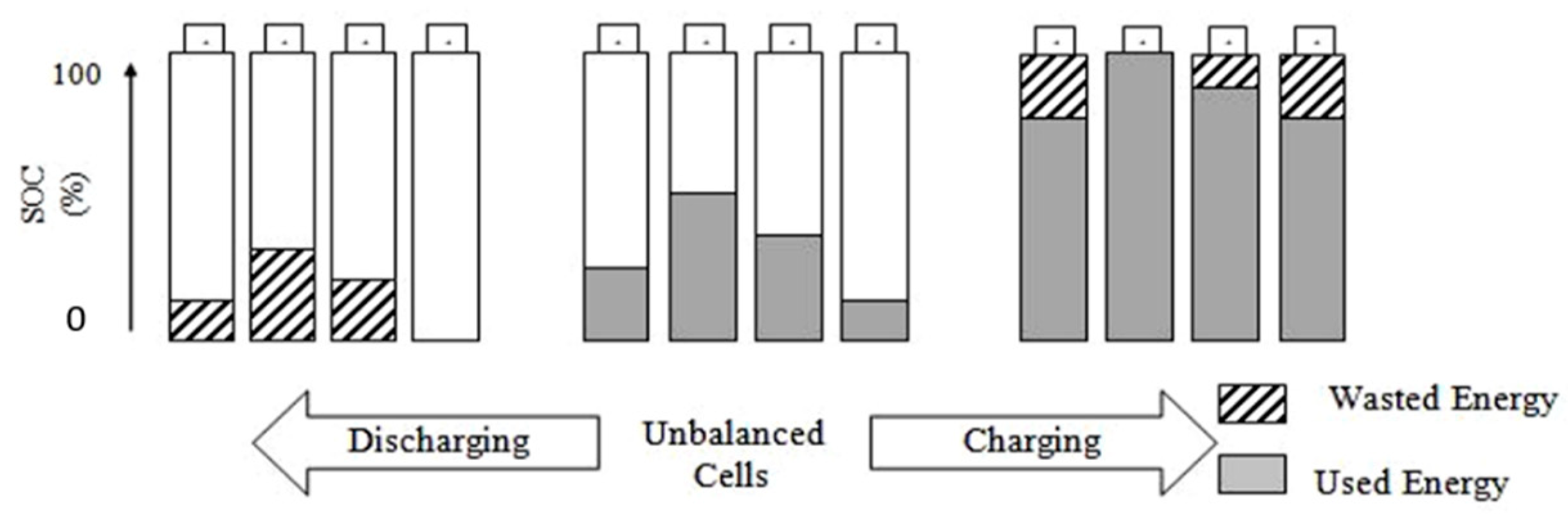
Table 6 [60], provides a comparison of commercially available BMS which are commonly used in EVs and plug-in-hybrid vehicles.
The next section describes cell balancing topologies and their comparison.

9. Cell Balancing

As described earlier, cell balancing is very crucial for a safe and reliable BMS operation. Cell balancing is a method of equalizing the voltages and SOC among the batteries when they are at a full charge. Even two cells of the same model and from the same manufacturer are not identical. There are always slight differences in SOC, voltage, current, impedance, and temperature characteristics, etc. Without a balanced system, the voltage of a particular cell will move exclusively over time and it will also reduce the overall pack capacity and battery arrangement will malfunction [61]. Three diverse cell adjusting procedures are generally utilized: charging, detached and dynamic [6,14]. Figure 6 and presents the possible causes of cell imbalance and their probable solutions. Cell balancing topologies can be categorized as active and passive cell balancing [5,6,14].

9.1. Passive Cell Balancing Techniques

In this approach, the cells with extra energy are dissipated through resistors until the charge equals that of the flatter cells in the pack or relating charge, impacting the overall battery life. Passive cell balancing technique is easy to execute, but less effective and should not be used during discharging. Shunt resistor cell balancing approach is the most simple which can be divided into fixed resistor and control shunt resistor. In the fixed shunt resistor method, the current is continuously bypassed and the voltage is limited by varying the resistor. In a controlled shunt resistor approach, controlled switches/relays are used instead of continuously discharging higher charged cells [35,48]. Table 7 shows the comparisons of these approaches [7,48,56].

9.2. Active Cell Balancing Techniques

The active cell balancing approach uses capacitive or inductive charge flowing to move from a high-charge cell’s charge to a low-charge cell. In this way, imbalance between cells is adjusted by transferring electrical energy from more crucial SOC cells to lower SOC cells with no damage. This method maximizes the battery’s available power and is more effective as compared to passive balancing techniques as the surplus energy is passed to a low energy cell rather than precipitated [6,13]. Active cell balancing has five different topologies as shown in the Figure 7 [6].
Cell bypass: In cell bypass, preferably each cell in a battery system has the same functionality, such that they all respond in the same way to several dynamic characteristics. Nevertheless, in the application, the actual cell property differs from cell to cell due to fluctuations in processing, environmental factors such as the string’s restricted temperature, or the cell’s changing loss state. Some cells would hold larger rates of self-discharge and internal resistances, making voltage variation and heating. Cells avoid equalization approaches neglect the cells’ potential that exceeds their highest/lowest voltage, expecting the remaining cells to achieve the highest/lowest voltage. [4,6,14].
Cell to cell: Cell to cell variations are essential for pack health as they can refer to various potentials for the battery packs or restricted deterioration in operation. Cell-cell strategies transfer the additional charge collected in the cells to the identical ones with less charge collected [6].
Cell to pack: In cell-to-box approaches, energy is collected from the multiple charged cells and distributed evenly to all cells by the pack connectors. This approach is secure as there is no energy damage in the form of heat since the additional charge that induces heat is, therefore, spelled from the cell to the extra cells in the case.
Pack to cell: Pack-to-cell techniques are used to transfer energy from the pack to the least charged cell. This system guarantees that the balance charge is sustained during the charging period and that no charge is dissipated. It requires lower number of switches, but high number of transformers as compared to the cell-to-pack method making the design complex and costly [5,6,15].
Cell pack to cell: Techniques shift energy through the application of both cells to pack and pack to cell techniques. In cell to cell, cell to pack, pack to the cell, and cell-pack-cell techniques, traditional DC/DC converter topologies appear multifaceted and costly, and their performance can be poor. These topologies are usually successful in limiting over-charging or over-charging of single battery cells, significant for pack protection along with durability. This approach has faster balancing speed, but complex and expensive to implement. Table 8 shows the comparison among active cell balancing topologies [5,6,15].
Table 9 shows a comparison among different active cell balancing techniques.
The next section presents the comparison between active and passive cell balancing by doing modeling and simulation.

10. Comparison between Passive and Active Cell Balancing

Active cell balancing exploits all the stored energy and maximizes the useable capacity of the battery with no loss of energy which does not happen in passive balancing methods. This approach is better for high cycle applications or when minimum losses are required. This approach also enhances the battery lifetime and capacity as compared to passive balancing. However, this approach requires extra components which increase balancing time, cost and unreliability [51,64]. As an example, assume that a battery pack has three cells X, Y, and Z having SOC levels at 85%, 75%, and 65%, respectively, before balancing. In case of passive cell balancing, energy will be dissipated from high SOC cells and all the cells will reach to same level of SOC as the lowest cell, i.e., cell Z (65%). This process reduces the overall system efficiency. In case of active cell balancing, energy will be shared among the cells by transferring the energy from higher cell X to lower cell Z, and thus the cells will acquire an equal SOC of 75% [16]. Figure 8 shows the comparison of these topologies [33].

10.1. Modeling of a Cell Balancer

A simulation was designed using MATLAB to develop the viability of an active balance device that can transfer energy from one cell to a bunch of cells. This simulation required examining the cell performance from a strict point of view of energy transfer and determining a balanced algorithm’s possible faults. This simulation is designed with eight-cell battery packs, can loop the system under a constant current level or a continuous power mode, uses a lithium-ion charging and discharge curve data structure, and can be worked with or without the balancing function. In Figure 9 [22], the configuration of the planned fly back balancer is shown. The primary side is connected to the entire stack of cells, and through a diode, each battery cell is associated with the secondary windings.
The secondary is such that, concerning the primary winding, their polarity is the opposite. When the key switch is switched on, the MOSFET, the energy is collected as a transformer flux [22,23]. It is unnecessary to move the energy collected to the secondary since the diode is reversed bias. The energy will be transferred to the secondary side in the following phase when the switch is switched off. Flyback is commonly used in power supplies, has a low price, and high-performance [65]. The additional benefits are that the primary and secondary sides are distributed, and multiple outputs and a positive range of negative outcome voltage can be provided. To properly follow the circuit, let us recognize that the MOSFET is working on two modes: when it is turned ON and the other time wherein it is turned off, so the voltage in the primary inductor is given by:
V L p = V B a t t e r y
T ( o n ) = D · T p
Here, Tp is called the period, and D is called the duty cycle for the primary current, which we can calculate as:
i L p = V B a t t e r y L   ·   T o n
For the next mode, which is when the MOSFET is turned OFF, the primary voltage will become:
V L P = V c e l l 1 n + V c e l l 2 n + + V c e l l m n
Here, n is called the duty ratio and m is the number of cells. So:
T ( o f f ) = ( 1 D )   ·   T p
The primary current during the OFF time can be written as: i L p = 0 .
Now introducing the volt-time, the second rule, the transfer function can now be written as:
T ( o n )   · V L P = V B a t t e r y   · D   ·   T p
T ( o f f ) · V L P = V C e l l m n ( 1 D )   · T p
From the last two expressions, we can write:
V B a t t e r y = n   ·   D 1 D   · V C e l l m
Now to measure the primary current, first the output power can be calculated as:
P o u t = V o u t   · I o u t
Now, if we consider that all the switches and the diodes used are ideal, we can say that their efficiencies would be 100%. From which we can conclude that the input and the output power are equal:
I P , a v e = P i n V B a t t e r y
So, to find the primary inductance, the usual equation for the inductor voltage can be written as:
V = L · d i d t     L P = V d i d t
and therefore:
L P = V B a t t e r y I · T o n ,
where:
T o n = D f   .
The flow chart in Figure 10 demonstrates the design algorithm for the eight-cell battery pack.
To understand this algorithm’s working, the SOC of the battery pack is predetermined in the system. To balance all the cells in the battery pack, the system will learn the SOC of each cell in the battery pack, and it will compare them with the reference cell voltage to balance them. If it fails to run normally, it will stop the system from protecting the vehicle from damage. If it runs normally, the system will estimate the charge of each cell, and it will charge or discharge the battery pack. The battery with an upper charge will discharge in terms of charging the batteries with a lower charge using switches. The system will balance in the nominal condition in terms of protecting the vehicle from damages.

10.2. Simulation of Active and Passive Cell Balancer in Simulink

In this work, a comparative simulation is performed between active and passive cell balancing techniques using MATLAB/Simulink. The prototype in Figure 11 demonstrates active cell balancing utilizing MATLAB/Simulink. In this procedure, eight cells are connected in series as a battery pack. The purpose is to make each cell SOC equal by applying the cell balancing technique—the initial voltage of batteries is assumed 7.2 voltages for each cell in the system. The design model consists of a linear transformer, diodes, MOSFET, MATLAB function, current and voltage measurement, scope, display, capacitor, and pulse generator.
In the beginning, the SOC of each cell is assumed 80%, 60%, 40%, and 20%, respectively, to all the cells in the battery pack. To make the eight-cell battery SOC, the same active cell balancing technique is applied. Each cell in the stack is with 7.2 nominal voltage and 5.4 rated voltage. As mentioned above, the batteries in the stack are at a different level, with each cell response time assumed at 30 s. Eight cell battery stacks are made by connecting cells in series. This model’s design is based on the flyback cell balancer, and four linear transformers are used. The primary side of those linear transformers is connected to the entire stack of cells, and through diodes, each battery cell is associated with the secondary windings. The secondary is such that their polarity is the reverse in terms of the main winding.
The energy is stored as a transformer flux when the main switch, the MOSFET, is turned on. Since the diode is reverse bias, it is pointless to transfer the energy obtained to the secondary. When the switch is turned off, the energy can be shifted to the secondary side in the following process. A MATLAB function is derived from following the design algorithm to balance the battery arrangement SOC using MOSFET. The design algorithm will operate the switching to charge the cell with low-level charged batteries in the pack from the system’s highly charged batteries. The batteries are connected to the bus selector to observe the output voltage, current, and the SOC from the eight-cell battery arrangement. This quantity can be analyzed from the scopes connected respectively. These quantities are also seen on display for real-time observation of the battery pack. In general, the batteries with a high level of charge will charge the batteries with less charge, and this can be continued till it balances the charge concerning the cells in the stack.
Figure 12 demonstrates a passive cell balancing circuit diagrams. Twelve volts and 2.6AHh are in the battery pack. It is composed of eight series-connected lithium-ion cells. Through IGBT, every cell is connected to the load resistance. The initial state of charge of a lithium-ion cell is assumed different for several cells in the pack. The SOC of each cell is different. The above model consists of several components: a resistor, IGBT, lithium-ion cell, MATLAB function, display, Bus selector, and scope. The state of charge value is given to the MATLAB function, where the code is compiled, comparing each cell’s state of charge. This system’s working is not very complex as it basically reduces the charge of the cells with high SOC to the lowest cell to balance it. The charge is dissipated in the form of heat. The algorithm designed for this cell balancer will compare the SOC between all eight cells, and the lowest charged battery cell will be taken as a reference to equalize the cell arrangement.
Cells are connected with IGBT; it is utilized as the switching device. When the SOC of all the eight cells is equaled, it will turn off, and the circuit will open. The resistor connected to the cells is required to resist the extra charge from the cells with more charge. Each resistor in the model has measured 3 Ohm resistance across the battery stack. Bus selector is interconnected to the batteries to observe voltage and current of the system. Furthermore, the developed passive cell balancer is simulated and the results are discussed as below.
The work has investigated the active and passive cell balancing by using a flyback converter.
Figure 13 and Figure 14 shows the graphs between voltage (volts) and time (seconds) and between current (Ampere) versus time (s) for active cell balancing technique, respectively, while Figure 15 and Figure 16 show current and voltage graphs for passive cell balancing technique, respectively.
There are eight cells connected in series to form a battery pack and explore the cell balancing techniques. The graph basically depicts the value of current and voltage at a particular value of SOC, so with time the value of SOC decreases and so as the value of current and voltage changes. As seen from the Figure 13 of active cell balancing, all the different cells have different voltages. One of them has the highest voltage such as cell 5 and the other one with the lowest such as cell 8. So, when the circuit is simulated for 400 s, it can be seen that the cell with the highest voltage is discharging and the cell with the lowest voltage is getting voltage back from the transformer. At a point of time, all the different voltages will be balanced and once that is achieved (which is approximately at 500 s), all the voltages will be discharged simultaneously. Similarly for Figure 14, it can be seen that the value of the current slightly decreases as we run the simulation for 400 s.
Now when we compare it with the passive cell balancing voltages in Figure 16, during the ON state, the charge with the more capacity will discharge first until it reaches the state wherein both the cells have been balanced. As seen from the Figure 16 for the passive cell balancing, when the time is set to 500 s the graph of the voltage goes down. The cell with the maximum voltage will decrease the most wherein the cell with the least voltage will decrease lot less as compared to the other one which is more obvious at 1000 s. When the run time is increased up to 2000 s, there will come a point wherein all the eight cells will be balanced at approximately 3.82 volts and the discharge would take place simultaneously. The cells in passive balancing technique also show transient conditions around 1500 s before they are balanced. Similarly, the Figure 15 shows the changes in current with respect to time accordingly. In passive cell balancing, we are using IGBT instead of MOSFET.
Now, based on our comparison between active and passive cell balancing, we found out that active cell balancing is much better and efficient as compared to passive cell balancing because active cell balancing stores energy in the transformer during the ON time and transfer it to the secondary during the off-time and suspend the cell while in the passive cell balancing, the energy stored in the section is discharged until the cell is balanced. Based on all the above results, we can conclude that active cell balancing is better than passive cell balancing. From the above experimental findings, we can see that the proposed cell balancing circuit can effectively balance the energy between cells and increase the battery pack’s lifespan.
The other method that can be used for balancing is called the forward converter method, which is less efficient than the flyback converter technique because it requires a supplementary circuit, RCD snubber, or an auxiliary winding to reset the core of the transformer. So, the flyback converter method requires just one switch to control all the cells on the primary and diodes at each cell’s output. There is a MOSFET used in this converter, and its main aim is to switch the frequency. The transformer has three sections with a saturable core. The leading feature of a flyback is that it will store all the energy in the transformer during the ON time, and when the system is OFF, it will be transferred to the secondaries. Here, when compared in both the flyback and the forward converter, a flyback’s advantages are that it does not require a reset winding on the primary end and not an additional diode and inductor on the secondary side. So, fewer components are needed for it, and it is effortless to implement.

11. Conclusions

Batteries are the heart of EVs. However, battery management is a major challenge for the widespread usage of EVs due to their safety, cost, and battery life issues, etc. This work comprehensively reviews different aspects of battery management system as compared to the existing works which discuss one or two aspects only. The work comprehensively describes different kinds of functions/features, requirements, BMS topologies, battery models and their comparisons as a contribution. Similarly, a comprehensive discussion of different challenges and recommendations to address those challenges has been presented as another contribution. These recommendations propose future trends of BMS emphasizing on advanced battery models, hybridized intelligent algorithms, advanced prognostic approaches, efficient prototype design, universal BMS, and BMS virtualization approaches, etc. Another contribution is the comprehensive comparison of different cell balancing techniques. Modeling of a cell balancer and comparison of active and passive cell balancing techniques with an eight cell battery pack by using MATLAB/ Simulink is also presented. The result shows that the energy can be balanced efficiently by active cell balancing technique and lifespan of the LIBS can be increased effectively further enhancing the efficiency of the EVs as compared to passive cell balancing.
This work has emphasized that BMSs are still in an early stage and still have many challenges, even when employing state of the art algorithms and using advanced models/approaches. Safety management, high-efficient operations and reliable maintenance are still the big challenges for the future EVs as BMS has to perform many sophisticated functions in real time to manage complex nature of batteries, deal with harsh environments and fulfill the requirements of future EVs, etc. The work makes it clear that it would be very difficult for EVs to become a widespread option of the community until existing challenges are addressed and advanced BMSs are designed. Overall, the work provides a comprehensive discussion, analysis, and recommendations which would also be very beneficial to automobile engineers and EVs manufacturers.

Author Contributions

Conceptualization, M.U.; Data curation, M.U. and G.A.; Formal analysis, M.U., S.H.; Funding acquisition, M.U.; Investigation, G.A. and M.U.; Methodology, M.U. and G.A.; Project administration, M.U. and S.H.; Resources, G.A.; Software, G.A., Validation, M.U., G.A. and S.H.; Visualization, G.A.; Writing—original draft, M.U.; Writing—review & editing, M.U., G.A. and S.H. All authors have read and agreed to the published version of the manuscript.

Funding

This work is funded by the deanship of scientific research at the Islamic University in Al-Madinah Al-Munawarra, KSA, under the (Takamul/11) 1441-1442 program.

Institutional Review Board Statement

Not applicable.

Informed Consent Statement

Not applicable.

Data Availability Statement

Not applicable.

Conflicts of Interest

The authors declare no conflict of interest.

References

  1. Ouyang, Q.; Han, Z.; Xu, C.; Wang, Z. Cell Balancing Control for Lithium-Ion Battery Packs: A Hierarchical Optimal Approach. IEEE Trans. Ind. Inform. 2019, 16, 5065–5075. [Google Scholar] [CrossRef]
  2. Vardwaj, V.; Vishakha, V.; Jadoun, K.; Jayalaksmi, N.; Agarwal, A. Various Methods Used for Battery Balancing in Electric Vehicles: A Comprehensive Review. In Proceedings of the 2020 International Conference on Power Electronics & IoT Applications in Renewable Energy and its Control (PARC), Mathura, Uttar Pradesh, India, 28–29 February 2020; pp. 208–213. [Google Scholar]
  3. Sangang, C.; Chen, F.; Li, B. Lithium-Ion Battery Management System for Electric Vehicles. Int. J. Perform. Eng. 2018, 14, 3184–3194. [Google Scholar]
  4. Liu, K.; Li, K.; Qiao, P.; Cheng, Z. A brief review on key technologies in the battery management system of electric vehicles. Front. Mech. Eng. 2019, 14, 47–64. [Google Scholar] [CrossRef] [Green Version]
  5. Liuv, J.; Song, W.; Lin, S.; Feng, Z.; Ding, Y. Investigation on dynamic equalisation performance of lithium battery pack management. IET Circuits Devices Syst. 2017, 11, 388–394. [Google Scholar] [CrossRef]
  6. Omariba, B.; Zhang, L.; Sun, D. Review of Battery Cell Balancing Methodologies for Optimizing Battery Pack Performance in Electric Vehicles. IEEE Access 2019, 7, 129335–129352. [Google Scholar] [CrossRef]
  7. Ahmad, A.B.; Ooi, C.A.; Ishak, D.; Teh, J. Cell Balancing Topologies in Battery Energy Storage Systems: A Review. Int. Conf. Commun. Comput. Electron. Syst. 2019, 547, 159–165. [Google Scholar]
  8. Duraisamy, T.; Deepa, K. Active cell balancing for electric vehicle battery management system. Int. J. Power Electron. Drive Syst. 2020, 11, 571–579. [Google Scholar] [CrossRef]
  9. Nguyen, N.; Oruganti, K.; Na, K.; Bien, F. An Adaptive Backward Control Battery Equalization System for Serially Connected Lithium-ion Battery Packs. IEEE Trans. Veh. Technol. 2014, 63, 3651–3660. [Google Scholar] [CrossRef]
  10. Abhay, S.J.; Anuj, K.; Mandar, G.; Neeraj, P.; Sangeeta, K. Battery Management System. Int. Res. J. Eng. Technol. 2020, 7, 118–123. [Google Scholar]
  11. Yinjiao, X.; Eden, W.; Kwok, L.; Pecht, M. Battery Management Systems in Electric and Hybrid Vehicles. Energies 2011, 5, 1840–1857. [Google Scholar]
  12. Vaideeswaran, V.; Bhuvanesh, S.; Devasena, M. Battery Management Systems for Electric Vehicles using Lithium Ion Batteries. Innov. Power Adv. Comput. Technol. 2019, 1, 1–9. [Google Scholar]
  13. Balasingam, B.; Ahmed, M.; Pattipati, K. Battery Management Systems-Challenges and Some Solutions. Energies 2020, 22, 2825. [Google Scholar] [CrossRef]
  14. Lelie, M.; Thomas, B.; Knips, M.; Nordmann, H.; Florian, R.; Hendrik, Z.; Sauer, D. Battery Management System Hardware Concepts: An Overview. Appl. Sci. 2018, 8, 534. [Google Scholar] [CrossRef] [Green Version]
  15. Hannan, M.; Lipu, M.H.; Hussain, A.; Mohamed, A. A review of lithium-ion battery state of charge estimation and management system in electric vehicle applications: Challenges and recommendations. Renew. Sustain. Energy Rev. 2017, 78, 834–854. [Google Scholar] [CrossRef]
  16. Shabani, B.; Biju, M. Theoretical Modelling Methods for Thermal Management of Batteries. Energies 2015, 8, 10153–10177. [Google Scholar] [CrossRef]
  17. Ali, M.; Amad, Z.; Sarvar, S.; Alvi, J.; Hee, K. Towards a Smarter Battery Management System for Electric Vehicle Applications: A Critical Review of Lithium-Ion Battery State of Charge Estimation. Energies 2019, 12, 446. [Google Scholar] [CrossRef] [Green Version]
  18. Omariba, Z.B.; Lijun, Z.; Dongbai, S. Review on Health Management System for Lithium-Ion Batteries of Electric Vehicles. Electronics 2018, 7, 72. [Google Scholar] [CrossRef] [Green Version]
  19. Aslan, E.; Yasa, Y. A Review on The Battery State of Charge Estimation Methods For Electric Vehicle Battery Management Systems. In Proceedings of the 11th International Conference on Electrical and Electronics Engineering, Bursa, Turkey, 28–30 November 2019; pp. 281–285. [Google Scholar]
  20. Hannan, M.; Murshadul, H.; Hussain, A.; Yushaizad, Y.; Ker, P. State-of-the-Art and Energy Management System of Lithium-Ion Batteries in Electric Vehicle Applications: Issues and Recommendations. IEEE Access 2018, 6, 19362–19378. [Google Scholar] [CrossRef]
  21. Fill, A.; Birke, K.P. Impacts of cell topology, parameter distributions and current profile on the usable power and energy of lithium-ion batteries. In Proceedings of the 2019 International Conference on Smart Energy Systems and Technologies (SEST), Porto, Portugal, 9–11 September 2019; pp. 585–592. [Google Scholar]
  22. Xiong, R.; Jiayi, C.; Quonking, Y.; Hongwen, H.; Sun, F. Critical Review on the Battery State of Charge Estimation Methods for Electric Vehicles. IEEE Access 2018, 6, 1832–1843. [Google Scholar] [CrossRef]
  23. Abbas, M.; Eung, S.K.; Seul, K.K. Comparative Analysis of Battery Behavior with Different Modes of Discharge for Optimal Capacity Sizing and BMS Operation. Energies 2016, 9, 812. [Google Scholar] [CrossRef] [Green Version]
  24. Pattipati, B.; Sankavaram, C.; Pattipati, K. System Identification and Estimation Framework for Pivotal Automotive Battery Management System Characteristics. IEEE Trans. Syst. Man Cybern. 2011, 41, 869–884. [Google Scholar] [CrossRef]
  25. Hariprasad, A.; Priyanka, I.; Sandeep, R.; Ravi, V.; Shekar, O. Battery Management System in Electric Vehicles. Int. J. Eng. Res. Technol. 2020, 9, 605–607. [Google Scholar]
  26. Khanal, A.; Timilsina, A.; Paudyal, B.; Ghimire, S. Comparative Analysis of Cell Balancing Topologies in Battery Management Systems. In Proceedings of the IOE Graduate Conference, Lisbon, Portugal, 24 May 2019; pp. 845–851. [Google Scholar]
  27. Bharanitharan, J.; Prashanth, V. Electric Vehicle Enhanced Range, Lifetime and Safety through Ingenious Battery Management; LION Smart GmbH: München, Germany, 2019. [Google Scholar]
  28. Bonfiglio, C.; Roessler, W. A cost optimized battery management system with active cell balancing for lithium ion battery stacks. In Proceedings of the IEEE Vehicle Power and Propulsion Conference, Dearborn, MI, USA, 7–10 September 2009; pp. 176–182. [Google Scholar]
  29. Aswinth, R. Battery Management System (BMS) for Electric Vehicles. Available online: https://circuitdigest.com/article/battery-management-system-bms-for-electric-vehicles (accessed on 15 June 2021).
  30. Shang, Y.; Cui, N.; Zhang, C. A Global Modular Equalizer Based on Forward Conversion for Series-Connected Battery Strings. IEEE J. Emerg. Sel. Top. Power Electron. 2018, 6, 1456–1469. [Google Scholar] [CrossRef]
  31. Räber, M.; Abdeslam, O.; Heinzelmann, A.; Ramirez, A. Performance estimation of a cell-to-cell-type active balancing circuit for lithium-ion battery systems. In Proceedings of the IEEE 26th International Symposium on Industrial Electronics (ISIE), Edinburgh, UK, 21 June 2017; pp. 735–742. [Google Scholar]
  32. Hemavathi, S. Overview of cell balancing methods for Li-ion battery technology. Energy Storage 2021, 3, 203. [Google Scholar] [CrossRef]
  33. Naguib, M.; Kollmeyer, P.; Emadi, A. Lithium-Ion Battery Pack Robust State of Charge Estimation, Cell Inconsistency, and Balancing: Review. IEEE Access 2021, 9, 50570–50582. [Google Scholar]
  34. Enrico, S. Introduction to Battery Management System. Available online: https://www.allaboutcircuits.com/technical-articles/introduction-to-battery-management-systems/ (accessed on 20 June 2021).
  35. Vulligaddala, B.; Vernekar, S.; Singamla, S.; Brandl, M.; Sriniv, M.B. A 7-Cell, Stackable, Li-Ion Monitoring and Active/Passive Balancing IC With In-Built Cell Balancing Switches for Electric and Hybrid Vehicles. IEEE Trans. Ind. Inform. 2019, 16, 3335–3344. [Google Scholar] [CrossRef]
  36. Lin, J.C. Development of a two-staged balancing scheme for charging lithium iron cells in series. IET Electr. Syst. Transp. 2016, 6, 145–152. [Google Scholar] [CrossRef]
  37. Ouyang, Q.; Chen, J.; Zheng, J.; Fang, H. Optimal Cell-to-Cell Balancing Topology Design for Serially Connected Lithium-Ion Battery Packs. IEEE Trans. Sustain. Energy 2017, 9, 350–360. [Google Scholar] [CrossRef]
  38. Dost, P.; Kipke, V.; Sourkounis, C. Direct active cell balancing with integrated cell monitoring. IET Electr. Syst. Transp. 2019, 9, 244–250. [Google Scholar] [CrossRef]
  39. Cassani, P.; Williamson, S. Significance of Battery Cell Equalization and Monitoring for Practical Commercialization of Plug-In Hybrid Electric Vehicles. In Proceedings of the Twenty-Fourth Annual IEEE Applied Power Electronics Conference and Exposition, Washington, DC, USA, 15–19 February 2009. [Google Scholar]
  40. Min, G.H.; Ha, J.I. Active cell balancing algorithm for serially connected li-ion batteries based on power to energy ratio. In Proceedings of the IEEE Energy Conversion Congress and Exposition (ECCE), Cincinnati, OH, USA, 1–5 October 2017; pp. 1550–1558. [Google Scholar]
  41. Hu, L.; Zhao, M.L.; Wu, X.B.; Lou, J.N. Cell balancing management for battery pack. In Proceedings of the 10th IEEE International Conference on Solid-State and Integrated Circuit Technology, Shanghai, China, 1–4 December 2010. [Google Scholar]
  42. André, B.; Wolfgang, K.; Stefan, L.; Sven, T.; Thilo, P.; Carsten, T. Scalable, Decentralized battery management system based on self organizing nodes. Archit. Comput. Syst. 2020, 121, 171–184. [Google Scholar]
  43. Xi, Z.; Dahmardeh, M.; Xia, B.; Fu, Y.; Mi, C. Learning of Battery Model Bias for Effective State of Charge Estimation of Lithium-Ion Batteries. IEEE Trans. Veh. Technol. 2019, 68, 8613–8628. [Google Scholar] [CrossRef]
  44. Subburaj, A.S.; Bayne, S.B. Analysis of dual polarization battery model for grid applications. In Proceedings of the IEEE 36th International Telecommunications Energy Conference, Vancouver, BC, Canada, 28 September–2 October 2014; pp. 46–53. [Google Scholar]
  45. Dickson, N.T.H.; Hannan, M.; Hossain, L.; Ker, P. State of Charge Estimation for Lithium-Ion Batteries Using Model-Based and Data-Driven Methods: A Review. IEEE Access 2019, 7, 136116–136136. [Google Scholar]
  46. Gaizka, S.; José, I.; Inmaculada, Z.; Francisco, J.; Oier, O. Analysis of the current electric battery models for electric vehicle simulation. Energies 2019, 13, 733–760. [Google Scholar]
  47. Daowd, M.; Omar, N.; Bossche, P.; Mierlo, J. Capacitor Based Battery Balancing System. World Electr. Veh. J. 2012, 5, 385–393. [Google Scholar] [CrossRef] [Green Version]
  48. Wu, S.L.; Chen, H.C.; Chien, C.H. A Novel Active Cell Balancing Circuit and Charging Strategy in Lithium Battery Pack. Energies 2019, 12, 4473. [Google Scholar] [CrossRef] [Green Version]
  49. Rong, X.; Bie, Z.; Hua, B.; Wang, J.; Liu, W. Coordinated charging strategy for battery switch station considering battery charging characteristics. In Proceedings of the IEEE PES Asia-Pacific Power and Energy Engineering Conference (APPEEC) 2013, Kowloon, China, 8–11 December 2013. [Google Scholar]
  50. Hossain, L.; Hannan, B.; Mohamad, H.; Sazal, M.; Indra, M. Intelligent algorithms and control strategies for battery management system in electric vehicles: Progress, challenges and future outlook. J. Clean. Prod. 2021, 292, 745–767. [Google Scholar]
  51. Yuqing, C.; Yuqiong, K.; Yun, Z.; Li, W.; Jilei, L.; Yanxi, L.; Zheng, L.; Xiangming, H.; Xing, L.; Naser, T.; et al. A review of lithium-ion battery safety concerns: The issues, strategies, and testing standards. ELSEVIER. J. Energy Chem. 2021, 59, 83–99. [Google Scholar]
  52. Brandl, M.; Gall, H.; Wenger, M.; Lorentz, V.; Fanucci, L.; Roncella, R.; Saletti, R.; Prochazka, W. Batteries and battery management systems for electric vehicles. In Proceedings of the 2012 Design, Automation & Test in Europe Conference & Exhibition, Dresden, Germany, 12–16 March 2012; pp. 971–976. [Google Scholar]
  53. Pham, V.; Van-Tinh, D.; Choi, W. A Low Cost and Fast Cell-to-Cell Balancing Circuit for Lithium-Ion Battery Strings. Electronics 2020, 9, 248. [Google Scholar] [CrossRef] [Green Version]
  54. Gabbar, H.; Othman, A.; Muhammad, R.A. Review of Battery Management Systems (BMS) Development and Industrial Standards. Technologies 2021, 9, 28. [Google Scholar] [CrossRef]
  55. Wang, Q.; Jiang, B.; Li, B.; Yuying, Y. A critical review of thermal management models and solutions of lithium-ion batteries for the development of pure electric vehicles. Renew. Sustain. Energy Rev. 2016, 64, 106–158. [Google Scholar] [CrossRef]
  56. Aritra, G. Possibilities and challenges for the inclusion of the Electric Vehicle (EV) to reduce the carbon footprint in the transport sector: A review. Energies 2020, 13, 2602. [Google Scholar]
  57. Ruifeng, Z.; Bizhong, X.; Libo, C.; Yongzhi, L.; Weiwei, Z.; Wei, W. State of the Art of Lithium-Ion Battery SOC Estimation for Electrical Vehicles. Energies 2018, 6, 853–890. [Google Scholar]
  58. Ankur, B.; Rakesh, K.; Aritra, G. Design of an optimized thermal management system for Li-Ion batteries under different discharging conditions. Energies 2020, 13, 5695. [Google Scholar]
  59. Clair, B. The Pivotal Role of Battery Management System on the Performance of Electric Vehicles. Available online: https://www.wevolver.com/article/the-pivotal-role-of-battery-management-systems-on-the-performance-of-electric-vehicles (accessed on 10 June 2021).
  60. Orion, B.M.S. Comparison among Commercially Available BMS. Available online: https://www.orionbms.com/comparison/ (accessed on 24 June 2021).
  61. Venkatesan, C.; Chandrashekhar, P.; Alagar, K.; Dharmaraj, G.; Robbi, R.; Aritra, G. State of charge estimation of lithium Ion battery for electrical vehicles using machine learning algorithms. World Electr. Veh. J. 2021, 12, 1–17. [Google Scholar]
  62. Meng, J.; Luo, G.; Ricco, M.; Swierczynski, M.; Daniel-Ioan, S.; Teodorescu, R. Overview of Lithium-Ion battery modeling methods for state-of-charge estimation in electrical vehicles. Appl. Sci. 2018, 8, 659. [Google Scholar] [CrossRef] [Green Version]
  63. Ricardo, V.; Miguel, B.; José, P.; Sílvio, M. Management System for Large Li-Ion Battery Packs with a New Adaptive Multistage Charging Method. Energies 2017, 21, 455–476. [Google Scholar]
  64. Daowd, M.; Omar, N.; Peter, V.D.B.; Mierlo, J.V. Passive and active battery balancing comparison based on MATLAB simulation. In Proceedings of the IEEE Vehicle Power and Propulsion Conference 2011, Chicago, IL, USA, 6–9 September 2011; pp. 1–7. [Google Scholar]
  65. Martin, M. Active Flyback Based Battery Management System with Proportional Balancing for Use in an Electric Race Car. Master’s Thesis, University of Texas at Arlington, Arlington, TX, USA, 2016. [Google Scholar]
Figure 1. A general diagram of a BMS [22].
Wevj 12 00120 g001
Figure 2. Basic framework (software & hardware) of a BMS. Adapted from [18].
Wevj 12 00120 g002
Figure 3. BMS functionalities [18].
Wevj 12 00120 g003
Figure 4. Effect of SOC imbalance on a battery pack (4-cell) [33].
Wevj 12 00120 g004
Figure 5. Classifications of battery modeling. Adapted from [4].
Wevj 12 00120 g005
Figure 6. Reasons for cell imbalances [6,14].
Wevj 12 00120 g006
Figure 7. Active balancing topologies [6].
Wevj 12 00120 g007
Figure 8. Comparison between active and passive cell balancing [33].
Wevj 12 00120 g008
Figure 9. Active Flyback Based Balancing [22].
Wevj 12 00120 g009
Figure 10. Flow chart of the algorithm.
Wevj 12 00120 g010
Figure 11. Active cell balancing using Simulink.
Wevj 12 00120 g011
Figure 12. Passive cell balancing using Simulink.
Wevj 12 00120 g012
Figure 13. Active cell’s voltage waveforms—Voltage (volts) vs. Time (seconds).
Wevj 12 00120 g013
Figure 14. Primary current waveform in steady state for active cell balancing—Current (Ampere) vs. time (s).
Wevj 12 00120 g014
Figure 15. Primary current waveform in steady state for passive cell balancing—Current (Ampere) vs. time (s).
Wevj 12 00120 g015
Figure 16. Voltage waveform in steady state for passive cell balancing—Voltage (volts) vs. time (s).
Wevj 12 00120 g016
Table 1. Comparison of SOC estimation methods for battery cells and battery pack [19].
Features Battery Cell MethodsBattery Pack Methods
HighestLowestHighestLowest
PrecisionAuto-Regressive GPRMLooking Up Table approachBias Correction approachBig cell Method
CostElectromechanical Impedance ModelLooking Up Table approachOne by One approachBig cell Method
Computation TimeElectromechanical ModelLooking Up Table approachBias Correction approachBig cell Method
ComplexityLooking Up Table approachElectromechanical Impedance ModelBig cell approachBias Correction Method
ApplicabilityAuto-Regressive GPRMElectromechanical Impedance ModelBias Correction approachBig cell Method
Table 2. Comparison of different approaches for SOH assessment [12].
Method/ModelsAdaptionAccuracyReal Time UsageUsage without Data
ElectromechanicalOutstandingOutstandingBetterBetter
Equivalent circuitNot goodBetterGoodGood
Semi-empiricalNot goodOutstandingBetterPoor
AnalyticalUnsatisfactorySatisfiedUnsatisfactoryUnsatisfactory
StatisticalBetterGoodGoodNot good
Table 3. Comparison of BMS topologies [42].
BMS TopologyReliabilityScalabilityFlexibility
CentralizedNot satisfactoryNot satisfactoryNot satisfactory
ModularizedNeutralPartially not satisfiedPartially not satisfied
DistributedPartial compliancePartial compliancePartial compliance
DecentralizedFully complianceFully complianceComplete fulfillment
Table 4. Comparison of battery models [3,4,12,18,46,47].
TypeAdvantagesDisadvantages
Electrochemical modelAccurately represent electrochemical process within the battery; accurate temperature & voltage measurement; better performance; simple; universal reliabilityLarge computational overheads; needs extensive domain knowledge & longer development time; needs testing under exact conditions; invasive operation needed for some measurements; real time measurement of some applications not possible; parameter identification is difficult
Reduced-order electric modelLess computational overhead; parameters identification in real timeLoss of information’s as compared to electrochemical model
Equivalent circuit modelSimple; Widely adopted in real time applications; good performance for low SOC range; accurate temperature distribution prediction; universally reliableLess internal underlying reactions/information; needs testing under exact conditions; invasive operation needed for some measurements; real time measurement of some applications not possible; parameter identification is difficult; requires extensive domain knowledge & longer development time
Heat generation modelWidely applied in real-time applications; reliableNot accurate enough to represent the thermal behavior of battery; needs domain knowledge & longer development time
Heat transfer modelCaptures temperature distribution; detect hot spots in high-heat generation applicationsLarge computational overheads for real-time applications; used for offline simulations.
Coupled electro-thermal modelModerately accurate; Moderate physical interpretabilityComplex; not suitable in real time applications
Data-driven model (Machine Learning Approaches, Filtering Approaches, Stochastic Approaches)Shorter development time; does not require extensive domain knowledge; high accuracy of voltage calculation
1-Machine Learning Approaches (Simple; good for non-linear systems)
2-Filtering Approaches (Used for state-space model; good for non-linear, Gaussian & non-Gaussian systems)
3-Stochastic Approaches (Considers degradation process time-dependency; Provides uncertainty about results)
Requires large amount of data; unpredictable black box model; efficiency depends on test data & training approaches; difficulty in parameters tuning
1-Machine Learning Approaches (Point estimated RUL, uncertainty about measured results)
2-Filtering Approaches (state-space model required, Point estimated remaining useful life)
3-Stochastic Approaches (Complex, Takes into account uncertain factors)
Hybrid approaches (Series/Parallel)Highly accurate; reliable; robustReliable only for certain situations & for defined time period.
Empirical modelsSimple, computationally efficientLimited capability of describing the terminal voltage
Table 5. Comparison of charging methods [4].
ApproachIssues
Constant current (CC)Low capacity utilization
Constant current (CC)Battery lattice may collapse
Constant current-constant voltage (CC-CV)Balancing issues for charging speed, energy loss & temperature variations
Multi stage constant current (MCC)Balancing issues for charging speed, capacity utilization & battery lifetime
Table 6. Comparison between commercially available BMS [60].
FeaturesOrion BMSLithiumate ProMK 3*8Mini BMS
Overcharge/discharge, thermal & overcurrent protectionCapableCapableCapableCapable
Cell & Pack Health MonitoringCapableCapableIn capableIn capable
Cell balancingCapableCapableCapableCapable
Field Programmable CapableCapableCapableIn capable
SOC monitoringCapableCapableOptionalSeparate
Charge/discharge current limits CapableCapableIn capableIn capable
Cell & Pack Internal Resistances CapableCapableIn capableIn capable
Trouble codes w/OBD-II freeze frame CapableIn capableIn capableIn capable
Simulation of ‘virtual’ PHEV battery CapableCapableIn capableIn capable
Programmable OBD-II support CapableIn capableIn capableIn capable
Centralized Design CapableIn capableIn capableIn capable
Supports external thermistors CapableIn capableCapableIn capable
CANBUS Interfaces 2 interfaces1 interfaceIn capableIn capable
Isolation Fault Detection CapableOptionalIn capableIn capable
Automotive grade locking connectors CapableIn capableIn capableIn capable
Easy to disconnect from battery CapableIn capableCapableIn capable
Supports dual ranging current sensors CapableIn capableIn capableIn capable
Programmable structure for all CAN messages CapableIn capableIn capableIn capable
Software for data logging & programming CapableIn capableIn capableIn capable
Cell voltage sampling rate 30 ms600–10,000 ms62.5 ms per cellN/A
Cell voltage measuring range 0.5–5 v2.04–4.54 v1.25–6.0 vN/A
Table 7. Comparison of passive cell balancing techniques [7,48,56].
TopologiesAdvantagesDisadvantageApplicationsBalancing SpeedElements
Needed to Balance n Cell
Charge/Discharge
Fixed shunt resistorSimple; low costContinuous energy dissipation reduces life span; effective for a small number of cells only; no controlled operation; excess heat generation; inefficientAppropriate for nickel and lead-acid batteries low power applicationsSatisfactoryn resistorsFixed
Controlled shunt resistorSimple; reliable; low cost; more efficientExcess energy diffused as heat, so short battery life; energy losses coz of high balance current; balancing speed is slow; useful during charging onlyAppropriate for LIBs; low power applications; suitable for EVs when 10 mA/Ah balancing currentGoodn resistors;
n switches
Bi-directional
Table 8. Comparison between active cell balancing topologies. Adapted from [6,12,52,53].
Category/
Topology
AdvantagesDisadvantagesCostBalancing Speed/
Efficiency
for N-Cells
Complexity in Control/Implementation
for N-Cells
Cell bypassHigh balancing efficiency; very fast and flexible; small size; used for low power applications; easy to perform; simple to modifyHigh current switches; decrease battery efficiency during normal operation; generally used at the end of the charge/discharge process when effectiveness is lowLowhigh/
moderate
Simple/
simple
Cell to cellModerate efficiency;
For switched capacitors& inductors (controlling balancing current not possible, so slow balancing speed); For qusia resonant scheme (higher effectiveness due to soft switching, but slow balancing speed)
Bulky; complex control; switch networkModeratemoderate/
moderate
High/
moderate
Cell to packSecure; no energy lostSlow balancing speed, especially for low voltage cells; high costHighLow/
average
Complex/
simple
Pack to cellRelatively simple; good efficiency; fastSlow balancing speed, especially for high voltage cells; complex; switch network; high isolation voltage of DC/DCHighLow/
low
Complex/
moderate
Cell to pack to cellFaster than the cell-to-pack and pack-to-cell, but still slow balancing speedTopologies based on DC/DC converters are complex & costly; low efficiencyHighAverage/
average
Simple/
high
Table 9. Comparison of active cell balancing techniques. Adapted from [7,8,12,18,62,63].
Scheme/
Technique
BenefitsDisadvantagesElements Required to Balance n Cells/Balancing SpeedCharge &
Discharge Strategy/
Control Strategy
Cost/
Size
Complete Shunting (Cell Bypass)High efficiency; low switch voltage stress; negligible power losslow power applications; high switch current stress; wide voltage range for converters4 n switches
/high
Bidirectional/
medium
Low/small
Shunting Resistor (Cell Bypass)Easy implementation; high speedlow power applications; low efficiencyn resistor
/satisfactory
Fixed/easyLow/small
Shunting Transistor (Cell Bypass)high speed, less complex; easily modularLess efficiency; low power applicationsmediumBidirectional/
Medium
Low/small
Single Switched
Capacitor
(Cell-to-Cell)
Efficient; low complexity; possibility of low and high power applications; low switch voltage stress; no closed-loop controlDifficult modularity; high switch voltage stress; highly complex1 resistor, 1 capacitor, n + 5 switches
/moderate
Bidirectional/hardHigh/large
Double-tiered
Switching
(Cell-to-Cell)
Lower balancing capacity currents; high power applications; easily modularizedRelatively low speed; high switch current stressn capacitors,
2n switches/satisfactory
Bidirectional/
Moderate
High/large
Cûk converter
(Cell-to-Cell)
Lower balancing currents; relatively efficient; high power applications; low switch voltage/current stressHigh control complexity; low implementationn + 1 inductors, n + 1 switches, n − 1 capacitors
/satisfactory
Bidirectional/hardMedium/
medium
PMW controlled converter (Cell-to-cell)Allows high power applications; efficient; low-speedComplex; relatively low switch voltage/
current stress
n inductors, n capacitors,
2n switches
/low
Bidirectional/
hard
Medium/
small
Quasi-Resonant
Converter
(Cell-to-Cell)
High power applications; low switch voltage/current stress; high efficiency; simple implementationHigh control complexityn inductors, n capacitors,
2n switches/
low
Bidirectional/
hard
high/
large
Shunting inductor (Cell-to-Pack)High power applications; relatively low switch current/voltage stressVery slow; highly complex; difficult modularityn − 1 inductor, 2n − 2 diodes/
medium
Bidirectional/
hard
Low/
small
Boost shunting (Cell-to- Pack)High power applications; efficient; easy modular design; low switch voltage/current stressHigh control complexityhighBidirectional/hardHigh/
small
Multi-secondary
winding transformer (Cell-to-Pack)
Allows high power applications; relatively high switch voltage stress; low switch current stressLess efficient; difficult modularity; control complexity; limited number of cells1 winding transformer, n + 1 inductors, 2 switches/lowCharge only/
hard
High/
large
Multiple transformers
(Cell-to-Pack)
Allows high power applications; easily modularized; fast equalization speedLess efficient; high complexity;
relatively high switch voltage/current stress
n diodes, 1 switch, 2n inductors, n winding transformers/
satisfactory
Bidirectional/
hard
High/
large
Modularized-
Switching transformer (Cell-to-Pack)
High power applications; relatively highly modular; low switching voltage/current stressHigh control complexity; less efficientLowBidirectional/
hard
High/
large
Voltage multiplier
(Pack-to-Cell)
High power applications; high efficiency; modularHigh switch voltage/current stresshighBidirectional/easylow/
moderate
Full-bridge converter (Pack-to-Cell)High efficiency; easy modularity; high power applications; low switch voltage/current stressHigh control complexityn capacitors, 4n switches/
high
Bidirectional/
hard
High/
large
Multiple transformers (Pack-to-Cell)High power applications; low complexity; fast equalization speedSlow; expensive; less efficientn diodes, 1 switch, 2n inductors, n winding transformers/satisfactoryBidirectional/
hard
High/
large
Multi-secondary
windings transformer
(Pack-to-Cell)
High power applications; high speed/
implementation; low switch current stress
Less efficient; control complexity; difficult modularity1 winding transformer, n + 1 inductors, 2 switches/lowCharge only/
hard
High/
large
Switched transformer
(Pack-to-Cell)
High power applications; low switch voltage/current stress; fast equalization speedLess efficient; high
control complexity
n + 3 switches, 1 transformer/highBidirectional/hardHigh/
large
PMW controlled
Converter (Cell-to-Pack-to-Cell)
high power applications; high efficiency
/speed/implementation
Less speed; relatively high switch voltage/current stress; high control complexityn inductors, n capacitors,
2n switches
/high
hardHigh/large
Single switched
Capacitor (Cell-to-Pack-to-Cell)
high efficiency; low switch voltage stress; applicable in high power applicationsLow balancing speed; high control complexity1 resistor, 1 capacitor, n + 5 switches/lowBidirectional/hardMedium/
small
Single switched inductor
(Cell-to-Pack-to-cell)
high efficiency; low switch voltage stress; applicable in high power applicationsSlow balancing speed; increased complexity2n switches,
2n − 2 diodes/
low
Bidirectional/hardMedium/
medium
Bi-directional multiple
transformers
(Cell-to-Pack-to-Cell)
Allows high power applications; easy modularityLess efficient; relatively high switch voltage/current stressn diodes, 1 switch, 2n inductors, n winding transformers
/satisfactory
Bidirectional/hardHigh/large
Bi-directional multi-
secondary windings
transformer
(Cell-to-Pack-to-Cell)
High power applications; relatively high speed/implementation; low switch current stressLess efficient; complex1 winding transformer, n + 1 inductors, 2 switches
/medium
Bidirectional/hardHigh/large
Bidirectional switched Transformer
(Cell-to-Pack-to-Cell)
Relatively high speed; allows high power applications; low switch current/voltage stress, and modularityLess efficient; complexn + 3 switches, 1 transformer/
medium
Bidirectional/hardHigh/large
Publisher’s Note: MDPI stays neutral with regard to jurisdictional claims in published maps and institutional affiliations.

