A Double Helix Flux Pipe-Based Inductive Link for Wireless Charging of Electric Vehicles


Abstract
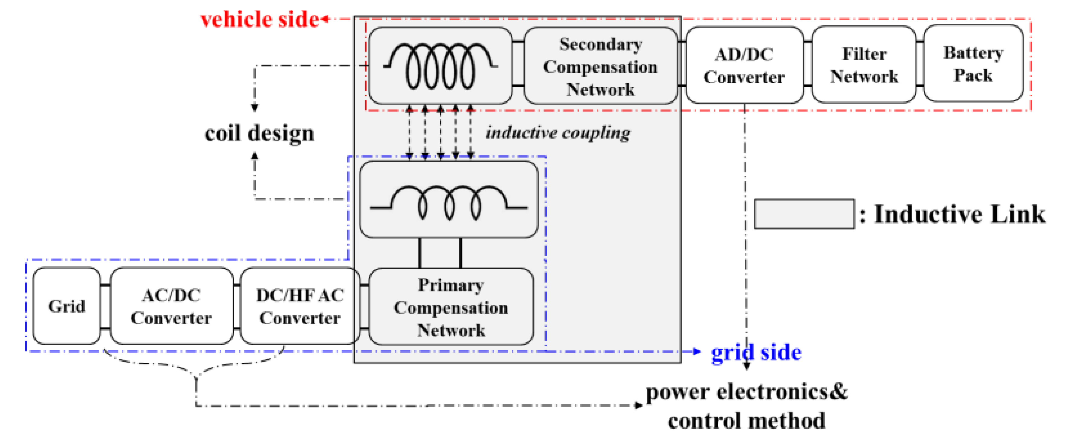
:1. Introduction
2. Double Helix Flux Pipe-Based Inductive Link
2.1. IPT System Using SS Topology
2.2. Flux Pipe for IPT System
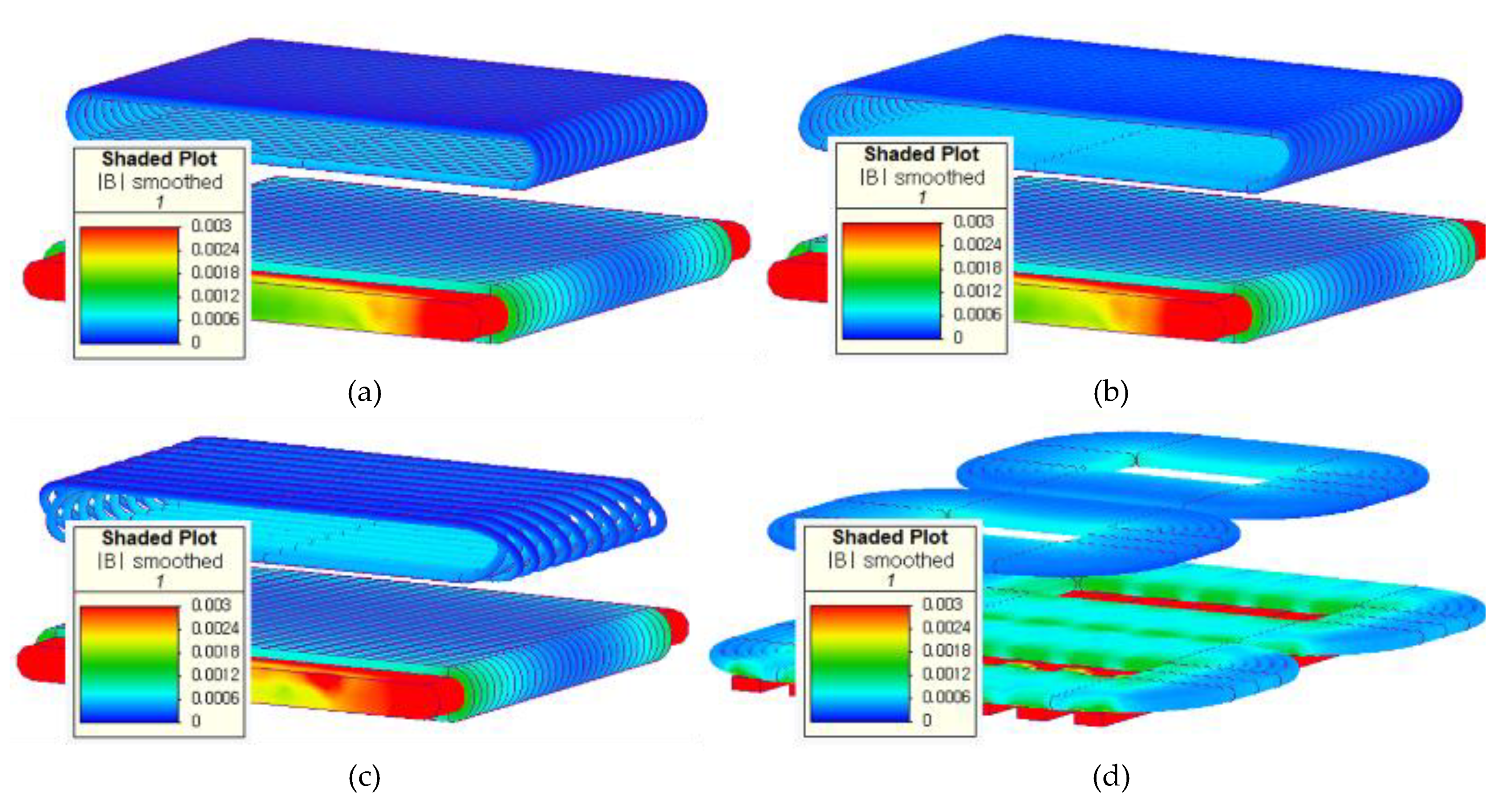
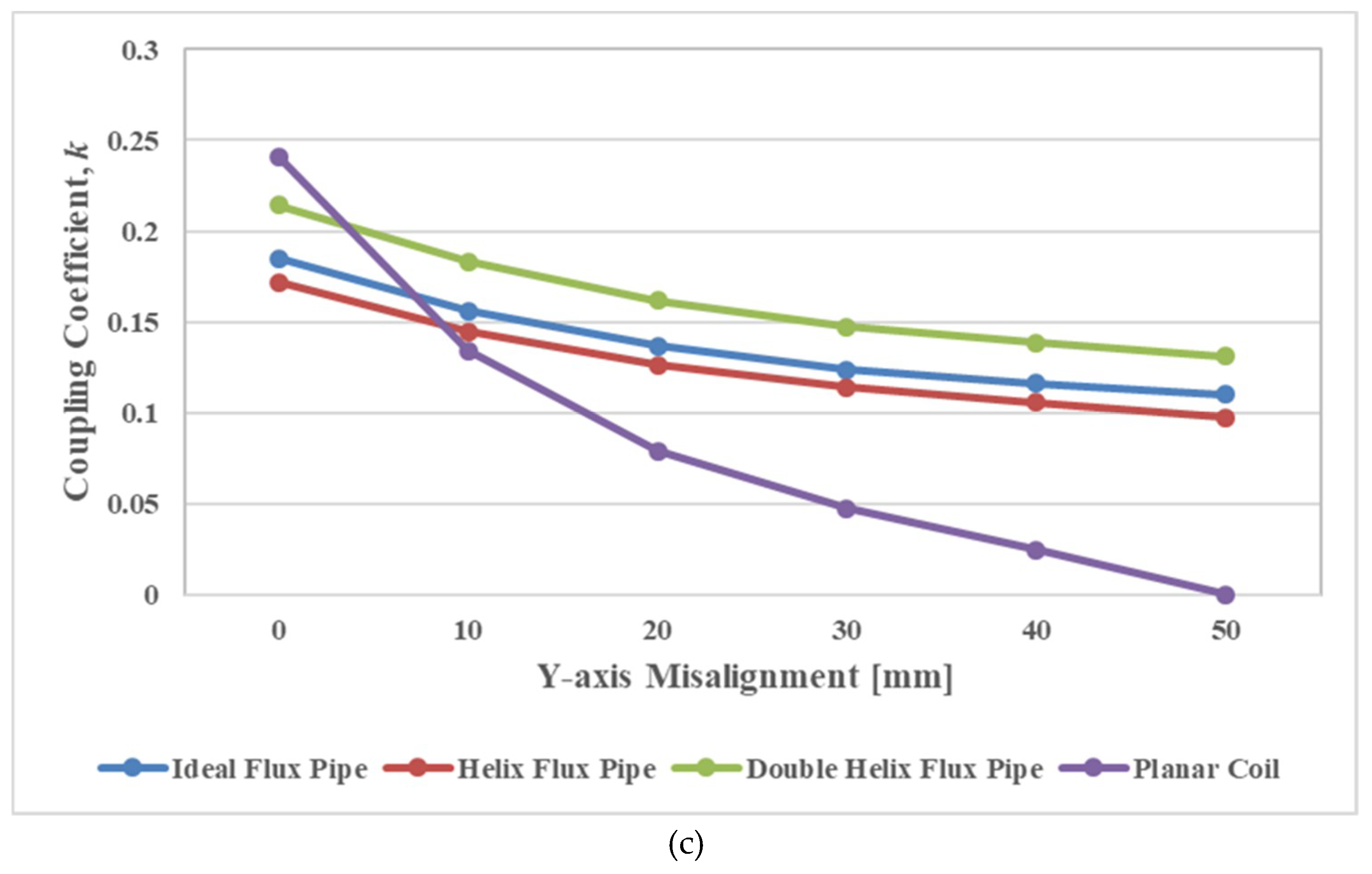
3. Characteristics Analysis
3.1. Coupling Coefficient Between Two Coils
3.2. Power Transfer Efficiency of IPT System
4. Discussion
5. Conclusion
Author Contributions
Acknowledgments
Conflicts of Interest
References
- Matias, R.; Cunha, B.; Martins, R. Modeling inductive coupling for wireless power transfer to integrated circuits. In Proceedings of the IEEE Wireless Power Transfer (WPT), Perugia, Italy, 15–16 May 2013; Volume 2, pp. 198–201. [Google Scholar]
- Kalwar, K.A.; Aamir, M.; Mekhilef, S. Inductively coupled power transfer (ICPT) for electric vehicle charging—A review. Renew. Sustain. Energy Rev. 2015, 47, 462–475. [Google Scholar] [CrossRef] [Green Version]
- Lempidis, G.; Zhang, Y.; Jung, M.; Marklein, R.; Sotiriou, S.; Ma, Y. Wired and wireless charging of electric vehicles. In Proceedings of the 2014 4th International Electric Drives Production Conference (EDPC), Nuremberg, Germany, 30 September–1 October 2014; pp. 1–7. [Google Scholar]
- Wang, R.; Zhou, X.; Zheng, J.; Yang, D. Research on the efficiency of wireless power transfer system based on multi-auxiliary transmitting coils. In Proceedings of the 4th International Conference on Information Science and Control Engineering (ICISCE), Changsha, China, 21–23 July 2017; pp. 1677–1681. [Google Scholar]
- Zhai, L.; Zhong, G.; Cao, Y.; Hu, G.; Li, X. Research on Magnetic Field Distribution and Characteristics of a 3.7 kW Wireless Charging System for Electric Vehicles under Offset. Energies 2019, 12, 392. [Google Scholar] [CrossRef] [Green Version]
- Ahmad, A.; Alam, M.S.; Chabaan, R. A Comprehensive Review of Wireless Charging Technologies for Electric Vehicles. IEEE Trans. Transp. Electrif. 2018, 4, 38–63. [Google Scholar] [CrossRef]
- Moon, H.; Kim, S.; Park, H.H.; Ahn, S. Design of a resonant reactive shield with double coils and a phase shifter for wireless charging of electric vehicles. IEEE Trans. Magn. 2015, 51, 8700104. [Google Scholar]
- Yang, Y.; Mohamaed, E.B.; Yuanfeng, L.; Yassine, B.; Joeri, V.M.; Omar, H. Design Methodology, Modeling, and Comparative Study of Wireless Power Transfer Systems for Electric Vehicles. Energies 2018, 11, 1716. [Google Scholar] [CrossRef] [Green Version]
- Cai, C.; Wang, J.; Fang, Z.; Zhang, P.; Hu, M.; Zhang, J.; Li, L.; Lin, Z. Design and Optimization of Load-Independent Magnetic Resonant Wireless Charging System for Electric Vehicles. IEEE Access 2018, 6, 17264–17274. [Google Scholar] [CrossRef]
- Li, Z.; Yu, C.; Liwen, L.; Tao, Z.; Steve, K. Mitigation Conducted Emission Strategy Based on Transfer Function from a DC-Fed Wireless Charging System for Electric Vehicles. Energies 2018, 11, 477. [Google Scholar]
- Li, S.; Mi, C. Wireless Power Transfer for Electric Vehicle Applications. IEEE J. Emerg. Sel. Top. Power Electron. 2015, 3, 4–17. [Google Scholar]
- Elnail, K.E.I.; Huang, X.; Xiao, C.; Tan, L.; Haozhe, X. Core Structure and Electromagnetic Field Evaluation in WPT Systems for Charging Electric Vehicles. Energies 2018, 11, 1734. [Google Scholar] [CrossRef] [Green Version]
- Imura, T.; Okabe, H.; Hori, Y. Basic experimental study on helical antennas of wireless power transfer for Electric Vehicles by using magnetic resonant couplings. In Proceedings of the 2009 IEEE Vehicle Power and Propulsion Conference (VPPC ’09), Dearborn, MI, USA, 7–10 September 2009. [Google Scholar]
- Sabki, S.A.; Tan, N.M.L. Wireless power transfer for electric vehicle. In Proceedings of the 2014 IEEE 8th International Power Engineering and Optimization Conference (PEOCO2014), Langkawi, Malaysia, 24–25 March 2014; pp. 41–46. [Google Scholar]
- Zhao, J.; Cai, T.; Duan, S.; Feng, H.; Chen, C.; Zhang, X. A general design method of primary compensation network for dynamic WPT system maintaining stable transmission power. IEEE Trans. Power Electron. 2016, 31, 8343–8358. [Google Scholar] [CrossRef]
- Kalwar, K.; Mekhilef, S.; Seyedmahmoudian, M.; Horan, B. Coil design for high misalignment tolerant inductive power transfer system for EV charging. Energies 2016, 9, 937. [Google Scholar] [CrossRef] [Green Version]
- Budhia, M.; Covic, G.A.; Boys, J.T. Design and Optimisation of Magnetic Structures for Lumped Inductive Power Transfer Systems. IEEE ECCE 2009, 2009, 2081–2088. [Google Scholar]
- Khaligh, A.; Dusmez, S. Comprehensive topological analysis of conductive and inductive charging solutions for plug-in electric vehicles. IEEE Trans. Veh. Technol. 2012, 61, 3475–3484. [Google Scholar] [CrossRef]
- Zhang, W.; Wong, S.-C.; Tse, C.K.; Chen, Q. Analysis and comparison of secondary series- and parallel-compensated inductive power transfer systems operating for optimal efficiency and load-independent voltage-transfer ratio. IEEE Trans. Power Electron. 2014, 29, 2979–2990. [Google Scholar] [CrossRef]
- Duan, C.; Jiang, C.; Taylor, A.; Bai, K. Design of a zero-voltage switching large-air-gap wireless charger with low electric stress for electric vehicles. IET Power Electron. 2013, 6, 1742–1750. [Google Scholar] [CrossRef]
- Boys, J.T.; Covic, G.; Green, A.W. Stability and control of inductively coupled power transfer systems. Proc. IEE Electr. Power Appl. 2000, 147, 37–43. [Google Scholar] [CrossRef]
- Chinthavali, M.; Zhiqiang, W.; Campbell, S. Analytical modeling of wireless power transfer (WPT) systems for electric vehicle application. In Proceedings of the 2016 IEEE Transportation Electrification Conference & Expo (ITEC 16), Dearborn, MI, USA, 27 June 2016; pp. 1–8. [Google Scholar]
- Spanik, P.; Frivaldsky, M.; Drgona, P.; Jaros, V. Analysis of proper configuration of wireless power transfer system for electric vehicle charging. ELELKTRO 2016, 2016, 231–237. [Google Scholar]
- Ishizaki, T.; Fukada, D.; Awai, I. A novel concept for 2-dimensional free-access wireless power transfer system using asymmetric coupling resonators with different sizes. In Proceedings of the IEEE MTT-S International Microwave Workshop Series on Innovative Wireless Power Transmission: Technologies, Systems, and Applications, Kyoto, Japan, 12–13 May 2011; pp. 243–246. [Google Scholar]
- Budhia, M.; Covic, G.A.; Boys, J.T.; Huang, C.Y. Development and evaluation of single sided flux couplers for contactless electric vehicle charging. In Proceedings of the IEEE Energy Conversion Congress and Exposition, Phoenix, AZ, USA, 17–22 September 2011; pp. 614–621. [Google Scholar]
- Babatunde, O.; Julius, P.; Richard, B. Finite Element Modeling and Analysis of High Power Low-loss Flux-Pipe Resonant Coils for Static Bidirectional Wireless Power Transfer. Energies 2019, 12, 3534. [Google Scholar]
- Nguyen, T.D.; Li, S.; Li, W.; Mi, C.C. Feasibility study on bipolar pads for efficient wireless power chargers. In Proceedings of the IEEE Applied Power Electronics Conference and Exposition-APEC, Fort Worth, TX, USA, 16–20 March 2014; pp. 1676–1682. [Google Scholar]
- Chigira, M.; Nagatsuka, Y.; Kaneko, Y.; Abe, S.; Yasuda, T.; Suzuki, A. Small-size light-weight transformer with new core structure for contactless electric vehicle power transfer system. In Proceedings of the IEEE Energy Conversion Congress and Exposition, Phoenix, AZ, USA, 17–22 September 2011; pp. 260–266. [Google Scholar]
- Takanashi, H.; Sato, Y.; Kaneko, Y.; Abe, S.; Yasuda, T. A large air gap 3 kW wireless power transfer system for electric vehicles. In Proceedings of the IEEE Energy Conversion Congress and Exposition (ECCE), Raleigh, NC, USA, 15–20 September 2012; pp. 269–274. [Google Scholar]
- Munir, A.B.; Kumar, N.; Karim, M.E.; Reza, A.W.; Barman, S.D. Wireless powering by magnetic resonant coupling: Recent trends in wireless power transfer system and its applications. Renew. Sustain. Energy Rev. 2015, 51, 1525–1552. [Google Scholar]
- Mizuno, T.; Yachi, S.; Kamiya, A.; Yamamoto, D. Improvement in efficiency of wireless power transfer of magnetic resonant coupling using magnetoplated wire. IEEE Trans. Magn. 2011, 47, 4445–4448. [Google Scholar] [CrossRef] [Green Version]
- Wojda, R.P. Winding resistance and power loss for inductors with litz and solid-round wires. IEEE Trans. Ind. Appl. 2018, 54, 3548–3557. [Google Scholar] [CrossRef]


| Type | Primary Capacitance, CP | Secondary Capacitance, CS | Load Resistance, RL |
|---|---|---|---|
| SS topology | |||
| PP topology | |||
| SP topology | |||
| PS topology |
| Parameter | Type I | Type II | Type III | Type IV |
|---|---|---|---|---|
| RX coil topology | Ideal solenoid | Helix | Double Helix | Planar (Double D) |
| Winding Turns of RX coil | 20 | 20 | 20 (inner 10/outer 10) | 20 (10 × 2 EA) |
| Helix angle | 0° | 45° | ±45° | N/A |
| Coil size (width × length) | 100 × 80 mm | 100 × 80 mm | 100 × 80 mm | 100 × 80 mm |
| RX coil Inductance, LS | 6.37 μH | 7.62 μH | 7.53 μH | 8.89 μH |
| Compensation capacitor, CS at secondary side | 550.25 nF | 459.69 nF | 465.50 nF | 394.23 nF |
| Quality factor, QS @ 85 kHz | 149.7 | 169.5 | 159.5 | 328.2 |
| TX coil topology | Solenoid with ferrite core | Planar (Double D) with ferrite core | ||
| Winding Turns of TX coil | 30 | 30 (15 × 2EA) | ||
| Coil size (width × length) | 100 × 90 mm | 100 × 90 mm | ||
| Ferrite core size (width × length) | 100 × 110 mm | 5 × 110 mm × (7 EA) | ||
| TX pad inductance, LP | 145.81 μH | 38.73 μH | ||
| Compensation capacitor, CP at primary side | 24.04 nF | 90.52 nF | ||
| Output power, POUT | 1 kW | 1 kW | 1.6 kW | 400 W |
| Gap distance | 20 mm | |||
| Litz wire dia. | 2.2 mm | |||
| Litz wire strands | 200 | |||
© 2020 by the authors. Licensee MDPI, Basel, Switzerland. This article is an open access article distributed under the terms and conditions of the Creative Commons Attribution (CC BY) license (http://creativecommons.org/licenses/by/4.0/).
Share and Cite
Hwang, Y.J.; Kim, J.M. A Double Helix Flux Pipe-Based Inductive Link for Wireless Charging of Electric Vehicles. World Electr. Veh. J. 2020, 11, 33. https://doi.org/10.3390/wevj11020033
Hwang YJ, Kim JM. A Double Helix Flux Pipe-Based Inductive Link for Wireless Charging of Electric Vehicles. World Electric Vehicle Journal. 2020; 11(2):33. https://doi.org/10.3390/wevj11020033
Chicago/Turabian StyleHwang, Young Jin, and Jong Myung Kim. 2020. "A Double Helix Flux Pipe-Based Inductive Link for Wireless Charging of Electric Vehicles" World Electric Vehicle Journal 11, no. 2: 33. https://doi.org/10.3390/wevj11020033