Article

Torque Ripple Reduction of DTC Based on an Analytical Model of PMSM

School of Automotive Studies, Tongji University, No. 4800 Cao’an Road, Jiading District, Shanghai 201804, China
*
Author to whom correspondence should be addressed.
World Electr. Veh. J. 2020, 11(1), 28; https://doi.org/10.3390/wevj11010028
Submission received: 23 January 2020 / Revised: 17 March 2020 / Accepted: 18 March 2020 / Published: 20 March 2020

Abstract

:
Aiming at the torque ripple problem of direct torque control that is based on space vector pulse width modulation (SVPWM-DTC) caused by the spatial harmonics and magnetic saturation characteristics of permanent magnet synchronous motor (PMSM), a feedforward controller based on an analytical model of PMSM was designed. An analytical motor model taking the spatial harmonics and magnetic saturation characteristics of PMSM into account by reconstructing the numerical solution of magnetic co-energy (MCE) from finite element analysis (FEA) was proposed. Based on that, the optimal stator flux linkage that minimizes the torque ripple is calculated and then a feedforward controller is designed and added to the SVPWM-DTC framework. Simulations and experiments are carried out and the results show that the proposed feedforward controller can effectively reduce the torque ripple of SVPWM-DTC.

1. Introduction

Permanent magnet synchronous motors (PMSM) have a lot of merits, such as high reliability, high efficiency, simple construction, and good control performance, thus, it is being increasingly applied on hybrid electrical vehicle (HEV)/electrical vehicle (EV) [1,2]. The normal operations of a PMSM need the support of high-performance control strategies. Field-oriented control (FOC) and direct torque control (DTC) are two well-established control strategies for the PMSM. When compared to FOC, DTC has better dynamic performance since it aims at the control of stator flux linkage and torque directly [3]. The use of hysteresis controllers of conventional DTC (CDTC) will cause significant torque and flux linkage ripple [4]. Many researchers have attempted to reduce these ripples through different schemes. Duty ratio modulation and space vector pulse width modulation (SVPWM) are two of the most popular schemes that have been widely accepted.
When compared to CDTC, duty ratio modulation for DTC (DDTC) is capable of regulating the applied time of the active vector in one period. There are different methods for the calculation of duty ratio [5]. Yuan et al. determine the applied time of the active vector by the active angle between flux linkage and the active voltage vector and the impact angle between flux linkage and the zero vector [6]. Mohan et al. propose a duty ratio calculation method that can reduce the flux dropping phenomenon in the low speed range [7]. DDTC could maintain the dynamic performance of CDTC without complex calculation and reduce the torque and flux ripple of CDTC. However, the introduction of the duty ratio could only regulate the amplitude of active vector. Consequently, the ability to mitigate the torque ripple is limited.
SVPWM can make the switching frequency of the controller stable and output the voltage vectors of arbitrary amplitude and phase angle. Therefore, it has been widely used in DTC and it can effectively suppress the torque ripple that is caused by hysteresis controllers [8,9]. SVPWM-DTC requires complex calculations and coordinate transformations, and it cannot maintain the good dynamic response performance of CDTC [10]. However, with the development of the control chip, the advantages of SVPWM-DTC will stand out, so this paper is based on the framework of SVPWM-DTC. However, SVPWM-DTC can only reduce the torque ripple that is introduced by hysteresis controller, not including the torque ripple caused by the spatial harmonics and magnetic saturation characteristics of PMSM.
The torque ripple that is caused by nonlinear characteristics of the motor could be suppressed by machine optimization [11,12] or active control of current harmonics [13,14,15,16,17]. For active control of current harmonics, the methods applied include PI control in multiple synchronous frames [14], proportional resonant (PR) [15], and repetitive control [16]. However, these methods are mainly focusing on eliminating the current harmonics, for the injection of current harmonics, the feedforward controller is a commonly used method [17,18]. The feedforward controller can effectively make up for the shortcomings of the insufficient bandwidth of the feedback closed-loop controller, but it requires an accurate motor model as a prerequisite [19]. A harmonic voltage model in a multi-synchronous coordinate system was derived and a feedforward harmonic voltage controller is designed in [17]. Zhong et al. proposed an accurate motor model that is based on magnetic common energy reconstruction, on this basis; a feedforward controller is designed to suppress the torque ripple [18]. These researches have achieved significant results in suppressing the torque ripple that is caused by the harmonic and magnetic saturation characteristics of the motor. However, these researches mainly focus on the framework of FOC, being rarely involved in DTC.
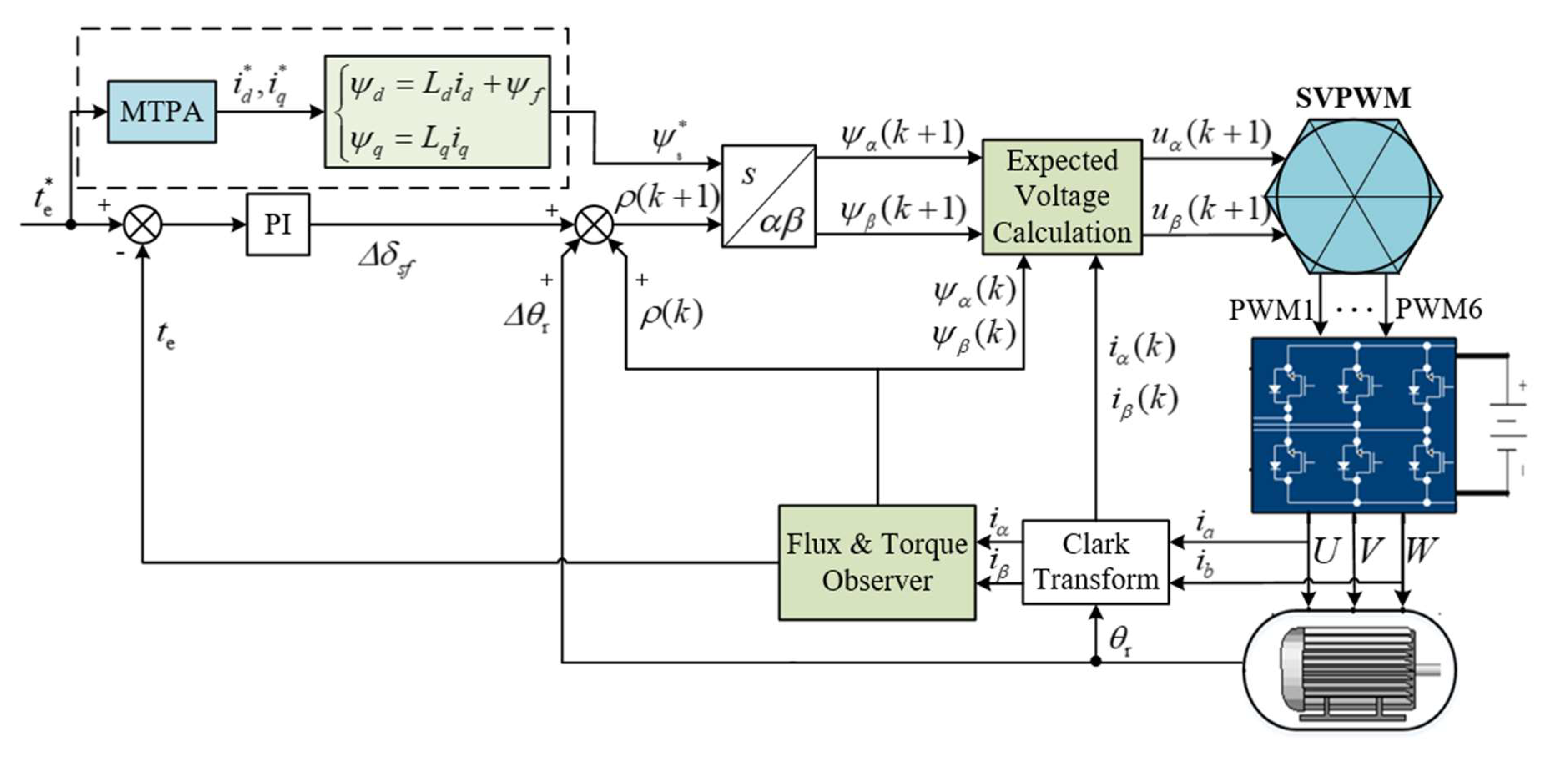
This paper proposed a novel feedforward controller for realizing the active suppression of torque ripple caused by non-linear characteristic of PMSM under the framework of SVPWM-DTC. When compared to FOC, the control object is converted from current harmonics into flux linkage harmonics. The basic principle of SVPWM-DTC was introduced firstly and then analytical model of PMSM was derived. After that, the calculation of the optimal flux linkage was demonstrated and a feedforward controller was then designed and applied in the SVPWM-DTC framework. Finally, the simulations and experiments were carried out and the results were analyzed. The results show that the proposed method is effective in the suppression of torque ripple.

2. SVPWM-DTC

2.1. Principle of SVPWM-DTC

The voltage model of PMSM is:
u s = R i s + d ψ s d t ,
where u s , i s , and ψ s are stator voltage, current, and flux linkage vector, respectively; R represents the stator resistance. When the control period is small enough, the voltage equation can be discretized as:
u s ( k + 1 ) = R i s ( k ) + ψ s ( k + 1 ) ψ s ( k ) T ,
where T represents the control period; k represents the values of present control cycle and k + 1 represents the values of next control cycle. In the α β reference frame, the decoupling of voltage equation can be achieved:
{ u α ( k + 1 ) = i α ( k ) R + ψ s * cos ρ s ( k + 1 ) ψ α ( k ) T u β ( k + 1 ) = i β ( k ) R + ψ s * sin ρ s ( k + 1 ) ψ β ( k ) T ,
where u α , u β , i α , i β , ψ α , and ψ β are components of stator voltage, current, and flux linkage vector in α - and β -axis respectively; ψ s * is the reference amplitude of stator flux linkage; ρ s is the angle between stator flux linkage vector and α -axis. The ψ s * could be expressed as:
ψ s = ( ψ d ) 2 + ( ψ q ) 2 = ( L d i d + ψ f ) 2 + ( L q i q ) 2 ,
where ψ d * , ψ q * , and i d * , i q * are reference values of stator flux linkage and current in d- and q-axis respectively; L d and L q are d- and q-axis inductances; and, ψ f represents rotor permanent magnet flux linkage.
The phase angle of next control cycle can be expressed as:
ρ s ( k + 1 ) = ρ s ( k ) + ω T + Δ δ sf ( k ) ,
where ω represents the electrical angular velocity, the product of ω , and T could approximate the increment of the rotor position Δ θ r ; Δ δ sf is the increment of load angle. The main feature of DTC is that the load angle δ sf is positively related to torque. Accordingly, Δ δ sf can be obtained through PI controller and this realizes the closed-loop control of torque.

2.2. Framework of SVPWM-DTC

Figure 1 shows the block diagram of SVPWM-DTC. The key of SVPWM-DTC is to calculate the voltage that is required for the next control cycle by flux linkage in present control cycle. The maximum torque per ampere (MTPA) is a look-up table that transfers the reference torque t e * into reference current i d * and i q * , and then ψ s * could be obtained by (4). The difference between the reference torque and the real torque feedback by torque observer is the input of PI controller, which outputs the increment of load angle Δ δ sf and ρ ( k + 1 ) could then be calculated by (5). The expected flux linkage ψ s ( k + 1 ) is then obtained. The flux linkage observer calculates the stator flux linkage ψ α , ψ β and feedback to the expected voltage calculation module. The torque and flux linkage observers are significant to DTC. A precise torque and flux linkage observer based on the analytical model of PMSM was applied in order to verify the proposed algorithm better. The observer takes the nonlinear characteristic of PMSM into account and requires not complex look-up tables, but simplified matrix operations. The voltage that is required for next control cycle u s ( k + 1 ) could be obtained by (3). The inverter outputs the required voltage vector by the SVPWM algorithm in the next control cycle and the torque control of PMSM is realized.
The control algorithm above is based on the assumption that the motor is linear without spatial harmonic and magnetic saturation characteristics. Under this case, the amplitude and the phase angle of the stator flux linkage is fixed when the real torque is constant. However, the actual motors are non-linear and they include the torque disturbances that are caused by cogging torque and the change of inductance to suppress this part of the disturbance, the PI controller needs to generate corresponding flux harmonics. However, when the speed of the motor rises up, it is difficult for the PI controller to track this part of flux linkage harmonics, due to the limitation of the bandwidth, which results in a large torque ripple of the motor.
Feedforward control can compensate for the insufficient bandwidth of the PI controller to a great extent. The optimal flux linkage harmonics that minimize the torque ripple can be obtained by the analytical model of the motor, which could be injected into the DTC control algorithm by a feedforward controller. This can better implement the control of the flux linkage harmonics and effectively suppress the torque ripple.

3. Feedforward Controller Based on Analytical Model of PMSM

3.1. Analytical Model of PMSM

The variation in magnetic co-energy (MCE) can clearly reflect the spatial harmonic and magnetic saturation characteristics of motor. Therefore, the numerical solution of MCE under several operating conditions was obtained from finite element analysis (FEA). It is a discrete data table with three dimensions that determine the MCE W c ( I s , β , θ r ) based on amplitude of the stator current vector I s , torque angle β, and rotor position θ r .
The reconstruction of MCE is to transform the discrete numerical solution into a continuous analytic solution. The MCE exhibits periodicity in both θ r and β dimensions. Therefore, a two-dimensional (2D) Fourier series decomposition can be applied to describe the MCE in θ r and β dimensions. Subsequently, the MCE can be expressed as:
W c k ( θ r , β ) = m 1 = N 1 N 1 m 2 = N 2 N 2 C m 1 , m 2 k e j m 1 θ r + j m 2 β ,
where N 1 and N 2 denote the highest Fourier series order of θ r and β, respectively; C m 1 , m 2 k is the Fourier coefficients with corresponding orders m 1 and m 2 ; k represents the different values of MCE and coefficients of different current amplitude I s k .
The polynomial fitting method was used to establish the relationship between C m 1 , m 2 k and I s k in order to further describe the changing law of W c k with respect to I s k , which can be expressed as:
C m 1 , m 2 ( I s ) = C m 1 , m 2 N 3 I s N 3 + C m 1 , m 2 N 3 1 I s N 3 1 + + C m 1 , m 2 n I s n + + C m 1 , m 2 1 I s + C m 1 , m 2 0 ,
where N 3 denotes the highest order of polynomial and C m 1 , m 2 n is the nth order of the polynomial coefficients. Combining all of the C m 1 , m 2 ( I s ) into one matrix, we have:
C ( I s ) = C N 3 I s N 3 + C N 3 1 I s N 3 1 + + C n I s n + + C 1 I s + C 0 .
Finally, the MCE is illustrated with matrix form:
W c ( I s , θ r , β ) = V ( θ r ) C ( I s ) U ( β ) ,
where V ( θ r ) and U ( β ) is the vector form of Fourier series in θ r and β dimension, respectively, which can be expressed as:
V ( θ r ) = [ e j N 1 θ r e j θ r 1 e j θ r e j N 1 θ r ] ,
U ( β ) = [ e j N 2 β e j β 1 e j β e j N 2 β ] T .
Here, the discrete numerical of MCE is transformed into a continuous analytic solution (9). The key of the model is the matrix C ( I s ) , which can describe the relationship of MCE with respect to rotor position θ r and stator current I s . The analytical model of flux linkage and torque can be derived from the relationship of MCE with respect to the flux linkage and torque, which can be expressed as:
[ ψ d ψ q ] = [ cos β sin β sin β cos β ] [ V ( θ r ) d C ( I s ) d I s U ( β ) V ( θ r ) C ( I s ) I s d U ( β ) d β ] ,
t e = 1.5 p [ d V ( θ r ) d θ r C ( I s ) U ( β ) V ( θ r ) C ( I s ) d U ( β ) d β ] .
The main difference between the analytical model and the traditional model is that the flux linkage and torque fluctuate with the rotor position θ r at a given current, that is, the spatial harmonics of PMSM can be reflected by V ( θ r ) . In addition, the relationship of the flux linkage and torque with respect to the current is obtained by fitting polynomials. It is no longer a simple linear relationship, and the magnetic saturation characteristics of the inductance can also be considered. The flux linkage and torque observers in this paper are constructed based on (12) and (13). The calculation of the optimal stator flux linkage is based on the analytical model.

3.2. Calculation of Optimal Stator Flux Linkage

The relationship between torque and current is linear over a wide range. Therefore, the cogging torque of PMSM could be balanced by the injection of current harmonics, which generates the torque harmonics of the same amplitude and opposite phase angle. The torque equation can be expressed as the first-order Taylor expansion at a specific operating point ( i d 0 ,   i q 0 ):
t e = t e ( i d 0 , i q 0 , θ r ) + t e i d | i d = i d 0 , i q = i q 0 × Δ i d + t e i q | i d = i d 0 , i q = i q 0 × Δ i q ,
where Δ i d and Δ i q is the difference between real current and fundamental current ( i d 0 ,   i q 0 ). The first term on the right side of (14) is the torque under the excitation of fundamental current; this part of torque includes cogging torque that can be described by the analytical torque model (13). Additionally it can be compensated by the last two terms of (14), so we need to find the appropriate current harmonics Δ i d and Δ i q . The stator current could be illustrated by vector I s or i d and i q , the relationship between them is:
{ I s = i d 2 + i q 2 β = arctan ( i q / i d ) .
Afterwards, t e / i d and t e / i q can be derived by (13) and (15). Let the left term of (14) equal 0, which means that the torque ripple is minimized, and then we can obtain the optimal current harmonics Δ i d and Δ i q under the specific operating point ( i d 0 ,   i q 0 ), which is the function of rotor position θ r :
Δ i x = V ( θ r ) [ i x [ N 1 ] i x [ N 1 + 1 ] 0 i x [ N 1 1 ] i x [ N 1 ] ] T ,
where x represents the d or q and i x k represents the amplitude of the kth harmonic in θ r dimension. In FOC, we can directly inject the current harmonics above, but in DTC we must convert it into flux linkage harmonics.
The first-order Taylor expansion of the d- and q-axis flux linkage at the operating point ( i d 0 ,   i q 0 ) can be illustrated as:
{ ψ d ( i d , i q , θ r ) = ψ d ( i d 0 , i q 0 , θ r ) + L dd Δ i d + L dq Δ i q ψ q ( i d , i q , θ r ) = ψ q ( i d 0 , i q 0 , θ r ) + L qd Δ i d + L qq Δ i q ,
where L represents the self-inductance and mutual inductance of the d- and q-axis, which can be expressed as:
{ L dd ( i d 0 , i q 0 , θ r ) = ψ d i d | i d = i d 0 , i q = i q 0 L dq ( i d 0 , i q 0 , θ r ) = ψ d i q | i d = i d 0 , i q = i q 0 L qd ( i d 0 , i q 0 , θ r ) = ψ q i d | i d = i d 0 , i q = i q 0 L qq ( i d 0 , i q 0 , θ r ) = ψ q i q | i d = i d 0 , i q = i q 0 .
From (17), we can see that the flux harmonics are mainly composed of two parts, the first one is the flux linkage spatial harmonic under the excitation of the fundamental current wave and the other is the flux linkage harmonic that is generated by the current harmonics. The former can be obtained by the analytical flux linkage model (12), and for the latter, ψ d / i d ,   ψ d / i q ,   ψ q / i d , and ψ q / i q could be derived from (12) and (15) and Δ i x are already obtained in (16). The sum of the two parts is the required optimal stator flux linkage vector.

3.3. Feedword Controller

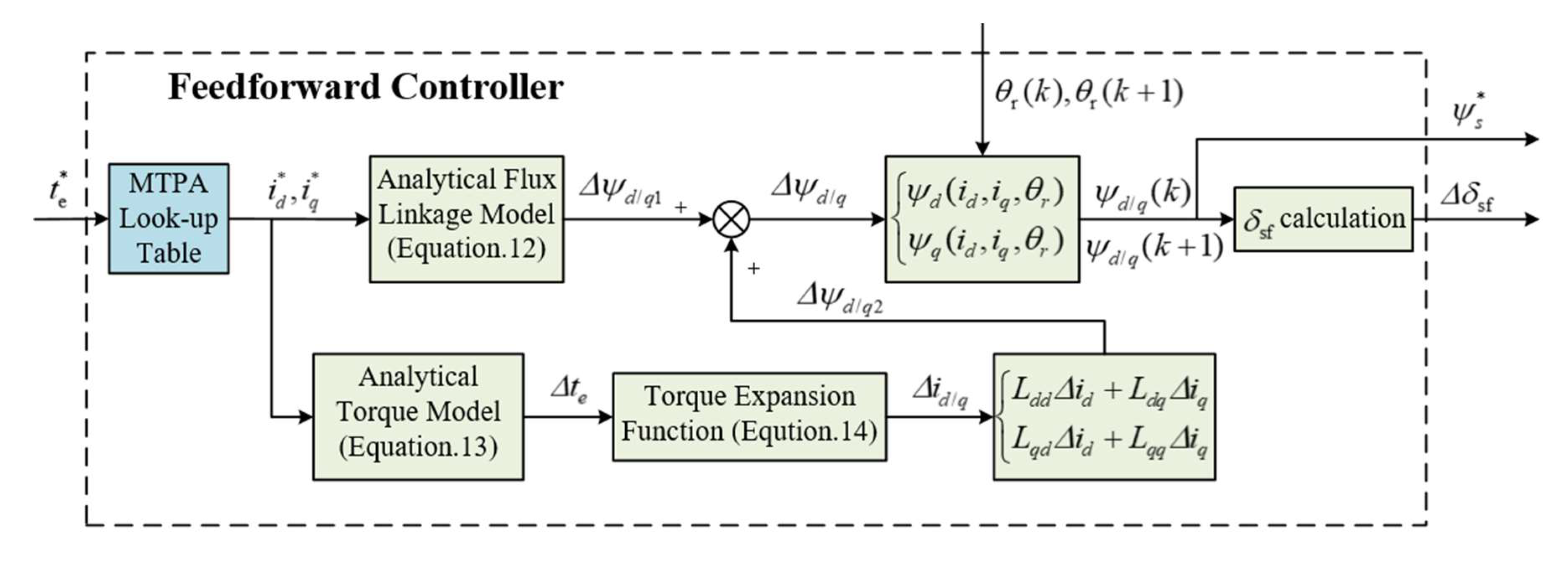
Figure 2 shows the calculation process of the optimal flux linkage. The reference torque t e * is converted into reference current i d * and i q * by MTPA. From the analytical flux linkage model (12) the first part of flux linkage harmonics Δ ψ d / q 1 in (17) can be obtained and from the analytical torque model (13) the torque harmonics Δ t e can be obtained. According to (14), the current harmonics Δ i d / q to balance the torque harmonics can be obtained and the second part of flux linkage harmonics Δ ψ d / q 2 in (17) can then be obtained. The sum of the two parts is the optimal flux linkage, which is the function of rotor position θ r . The rotor position of the present control cycle θ r ( k ) could be obtained by the sensor and rotor position of next control cycle θ r ( k + 1 ) is the cumulative values of θ r ( k ) and Δ θ r , which could be represented by the product of angular speed ω and control period T approximately. Subsequently, the load angle increment Δ δ sf required for the suppression of torque disturbance that is caused by cogging and magnetic saturation of PMSM is calculated and added to PI controller. The dashed box part in Figure 1 could be replaced by Figure 2 and the feedforward controller of optimal flux linkage is established.

4. Simulation and Experiment Result

4.1. Simulation Result

The simulation of the control algorithm above was carried out with the FEA PMSM model that takes the non-linear characteristics into account, whose parameters are shown in Table 1. It is a motor designed for hybrid electric vehicle (HEV) with three pole pairs and 36 slots, which will result in 12th torque harmonic. The SVPWM-DTC with and without feedforward controller was built in Simulink and 
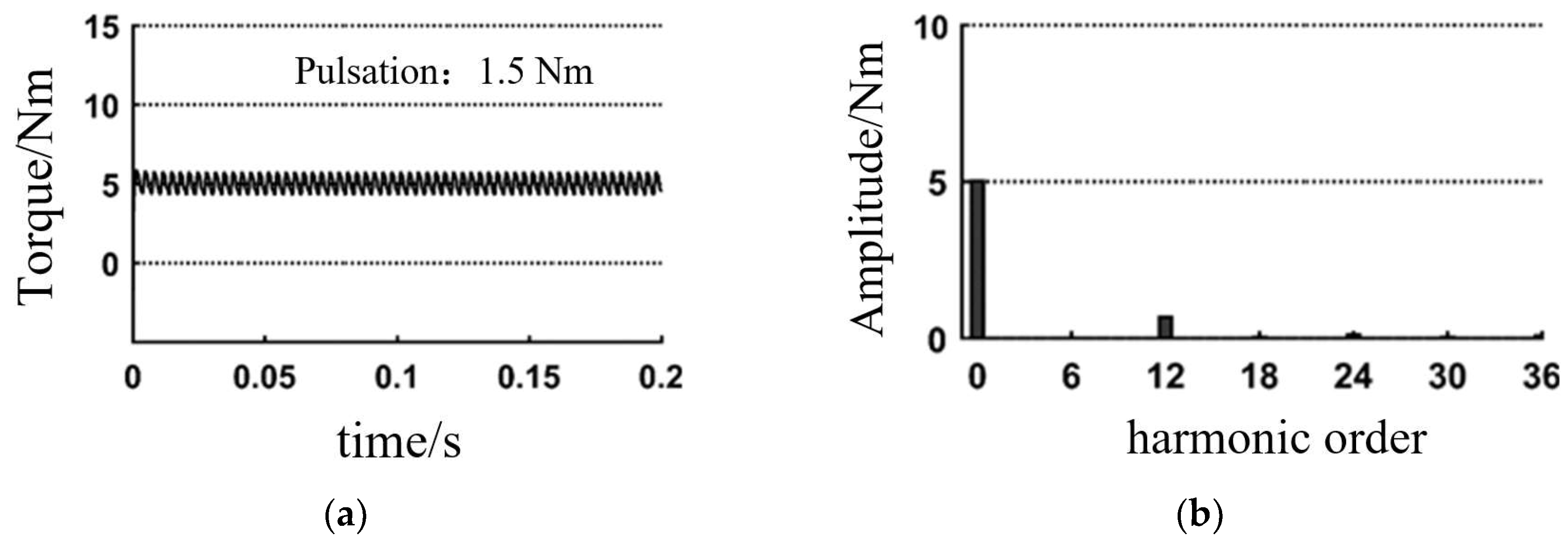
Table 2 shows the simulation parameters. The torque wave of the motor model was observed and the fast Fourier transform (FFT) analysis of it was conducted.
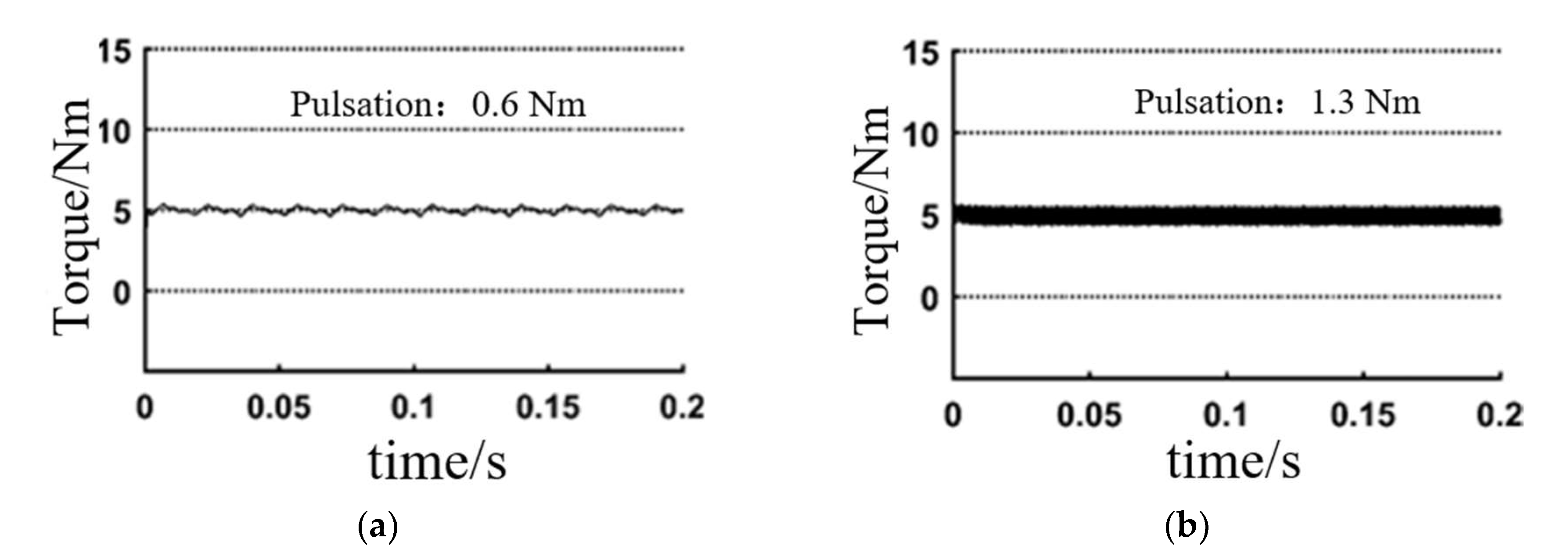
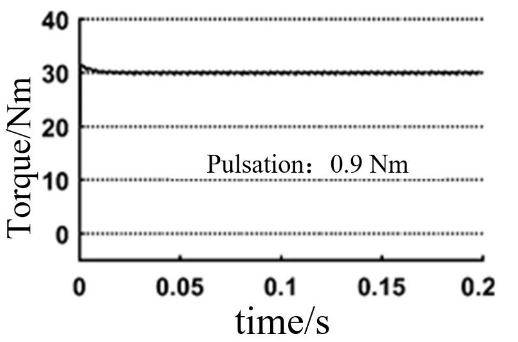
From Figure 3a and Figure 4a, it can be intuitively seen that the torque pulsation of the SVPWM-DTC control algorithm with the feed forward controller is reduced from 1.5 Nm to 0.8 Nm, with a decrement of 46.7%. It can be seen from the FFT analysis that this is mainly due to the suppression of 12th torque harmonic. The optimal stator flux linkage harmonic that was obtained according to the analytical PMSM model was added to the PI controller and the bandwidth problem of the PI controller was effectively solved. The torque disturbance caused by the spatial harmonics and magnetic saturation characteristics of the motor was suppressed.

4.2. Applicability Analysis

We set the motor speed to 100 rpm and 2000 rpm, respectively, in order to verify the applicability of the improved algorithm under other conditions. Other simulation conditions are the same as in Table 2. Figure 5 shows the torque response.
It can be seen that the control of torque ripple deteriorates with the increase of rotational speed. Voltage harmonics ultimately achieve the injection of flux linkage harmonics. When the mechanical motor speed is 2000 rpm, the number of pole pairs is 3, and the frequency of 12th voltage harmonic is 1.2 kHz. At this time, it is difficult to output the voltage vector by the inverter whose switching frequency is 10 kHz, which results in poor control of the torque.
To verify The reference torque is set to 30 Nm and other simulation conditions are the same as in Table 2 to verify the torque ripple suppression effect under high load. Figure 6 shows the torque response. It can be seen that the algorithm can maintain a good torque ripple suppression effect under high load.

4.3. Experiment Result

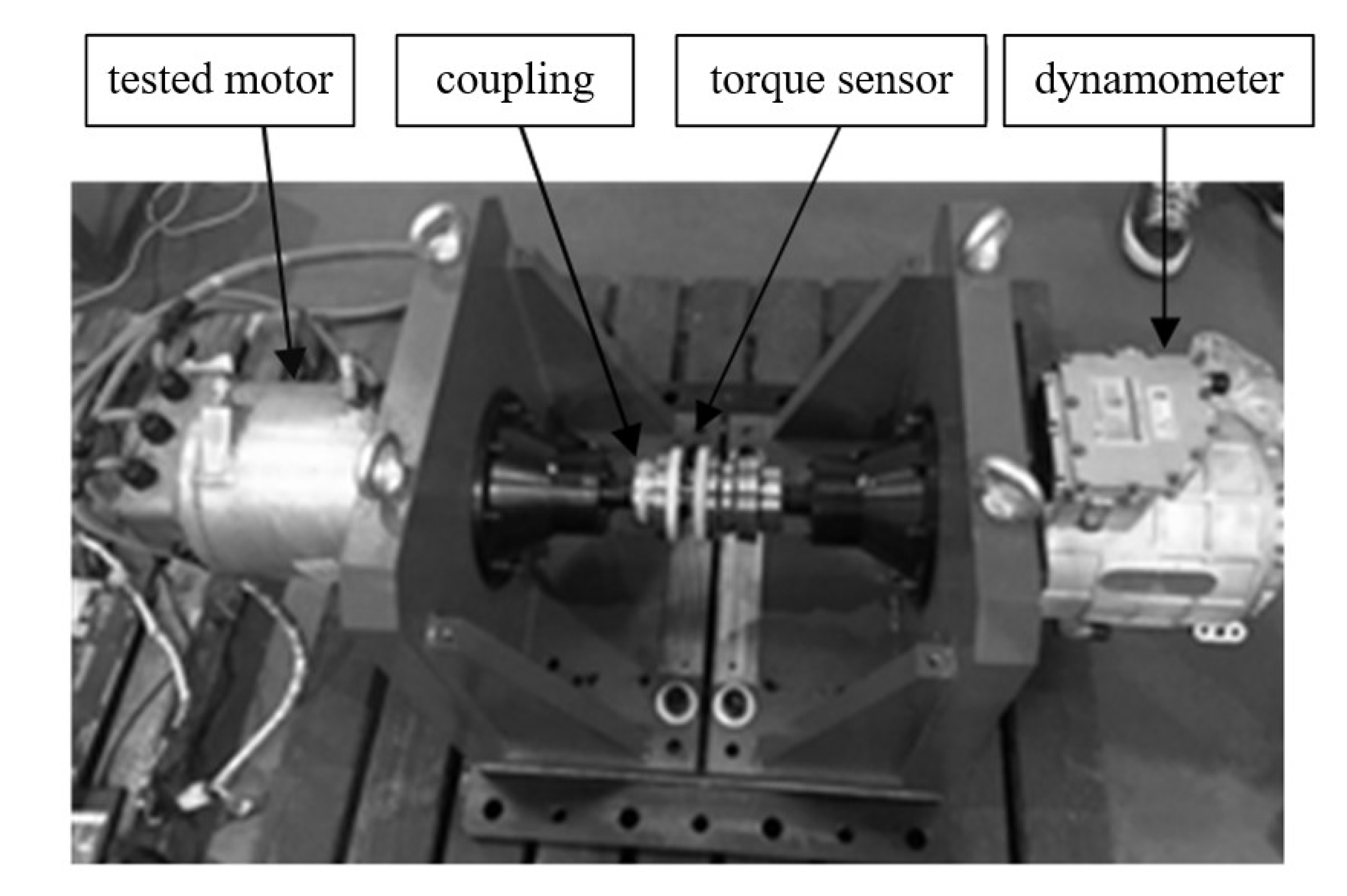
Based on the simulation, experiments further verified the feedforward controller. The experiments were carried out on the motor test bench shown in Figure 7. It is mainly composed of a dynamometer and the motor under test. The control algorithm is implemented by the motor controller, Semikron, whose inverter is IGBT and its maximum switching frequency is 10 kHz, so the period of the control cycle was set as 1 × 10⁻⁴. CAN realized the communication between the controller and the computer. The working point is the same as the simulation. The control algorithms with and without feedforward controller are separately tested under the same condition. The torque response was measured by the torque transducer and Figure 8 and Figure 9 show the results.
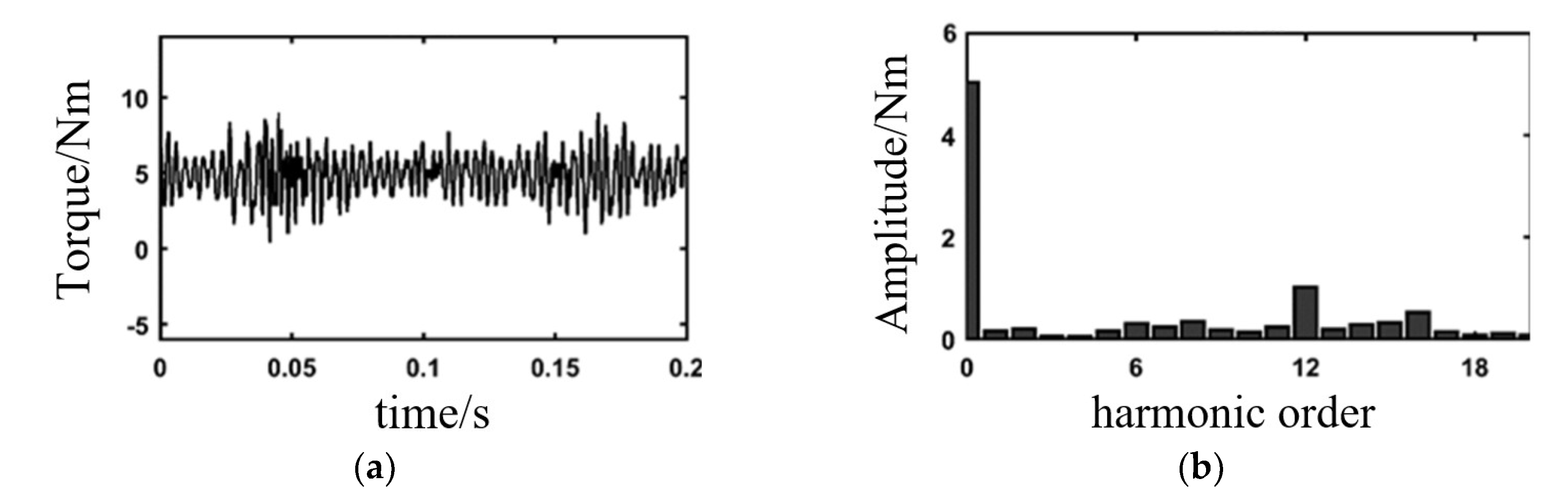
It can be seen from results that the torque ripple is larger than the simulation. From the FFT analysis of torque wave, it can be found that other than 6th, 12th, 18th harmonics caused by the slot of the motor itself, the torque ripple contains many harmonics of other orders that are introduced by factors, like dynamometer and the test bench, whose amplitude is not negligible. However, after the introduction of the feedforward controller, the torque ripple is greatly reduced and, from FFT analysis, we can see that the 12th torque harmonic is reduced by 60.28%. The test results are consistent with the simulation.
In conclusion, the experimental results are consistent with the simulation results and the SVPWM-DTC that is based on distributed parameter model has achieved remarkable results in torque ripple reduction.

5. Conclusions

This paper proposes an optimal flux linkage feedforward control method for suppressing the torque ripple that is caused by the nonlinear characteristics of PMSM under SVPWM-DTC framework. An analytical PMSM model that was based on the reconstruction of MCE was derived as the prerequisite for feedforward control. The optimal stator flux linkage is calculated by the analytical model, and the load angle is added to the PI controller in a feedforward way. Experiments simulated and verified the algorithm. The results showed that, when compared with the control strategy without feedforward, the SVPWM-DTC with feedforward controller has significantly reduced the torque ripple. The control quality of DTC is improved to a great extent.

Author Contributions

Conceptualization, Z.Z.; methodology, J.Y.; validation, J.Y. and S.Z.; formal analysis, J.Y. and S.Z.; writing—original draft preparation, J.Y.; writing—review and editing, J.Y. All authors have read and agreed to the published version of the manuscript.

Funding

This research received no external funding.

Conflicts of Interest

The authors declare no conflict of interest.

References

  1. Buja, G.S.; Kazmierlowski, M.P. Direct torque control of PWM inverter-fed AC motors—A survey. IEEE Trans. Ind. Electron. 2004, 51, 744–757. [Google Scholar] [CrossRef]
  2. Cassio, T.; Fabio, S.; Fabien, C.; Stefano, O. Noise emissions on switched reluctance motors: Evaluation of different structural models. World Electr. Veh. J. 2015, 7, 179–186. [Google Scholar]
  3. Takahashi, I.; Noguchi, T. A new quick-response and high efficiency control strategy of an induction motor. IEEE Trans. Ind. Appl. 1986, 22, 820–827. [Google Scholar] [CrossRef]
  4. Xia, C.; Wang, S.; Gu, X.; Yan, Y.; Shi, T. Direct torque control for VSI-PMSM using vector evaluation factor table. IEEE Trans. Ind. Electron. 1986, 63, 4571–4583. [Google Scholar] [CrossRef]
  5. Ren, Y.; Zhu, Z.; Liu, J. Direct torque control of permanent-magnet synchronous machine drives with a simple duty ratio regulator. IEEE Trans. Ind. Electron. 2014, 61, 5249–5258. [Google Scholar] [CrossRef]
  6. Yuan, T.; Wang, D.; Wang, X.; Wang, X.; Li, Y.; Yan, X.; Tan, S.; Zhou, S. Duty Ratio Modulation Strategy to Minimize Torque and Flux Linkage Ripples in IPMSM DTC Systems. IEEE Access 2017, 5, 14323–14332. [Google Scholar] [CrossRef]
  7. Mohan, D.; Zhang, X.; Foo, G. A simple duty cycle control strategy to reduce torque ripples and improve low-speed performance of a three-level inverter fed DTC IPMSM Drive. IEEE Trans. Ind. Electron. 2017, 64, 2709–2721. [Google Scholar] [CrossRef]
  8. Fan, Y.; Zhang, L.; Cheng, M.; Chau, K. Sensorless SVPWM-FADTC of a new flux-modulated permanent-magnet wheel motor based on a wide-speed sliding mode observer. IEEE Trans. Ind. Electron. 2015, 62, 3143–3151. [Google Scholar] [CrossRef] [Green Version]
  9. Sun, X.; Gao, Q.; Sun, W. Direct torque control of permanent magnet synchronous motor based on space vector PWM. Electr. Drive 2016, 46, 3–6. [Google Scholar]
  10. Abosh, A.; Zhu, Z.; Ren, Y. Reduction of torque and flux ripples in space vector modulation-based direct torque control of asymmetric permanent magnet synchronous machine. IEEE Trans. Power Electron. 2017, 32, 2976–2986. [Google Scholar] [CrossRef]
  11. Islam, R.; Husain, I. Permanent-magnet synchronous motor magnet designs with skewing for torque ripple and cogging torque reduction. IEEE Trans. Ind. Appl. 2007, 45, 152–160. [Google Scholar] [CrossRef]
  12. Kim, K. A novel method for minimization of cogging torque and torque ripple for interior permanent magnet synchronous motor. IEEE Trans. Magn. 2014, 50, 793–796. [Google Scholar] [CrossRef]
  13. Zhou, S.; Dai, B.; Zhong, Z. PMSM torque ripple suppression method based on distributed parameter and harmonic balance method. J. Tongji Univ. (Nat. Sci.) 2018, 46, 87–99. [Google Scholar]
  14. Xu, S.; Fei, S.; Zhao, J. Harmonic current frequency dividing control strategy based on synchronous rotating frame. Trans. China Electrotech. Soc. 2016, 31, 154–162. [Google Scholar]
  15. Yang, K.; Xie, C.; Chen, G. Frequency adaptive resonant controller based current control of SVG. Trans. China Electrotech. Soc. 2014, 29, 248–254. [Google Scholar]
  16. Mattavelli, P.; Tubiana, L.; Zigliotto, M. Torque-ripple reduction in PM synchronous motor drives using repetitive current control. IEEE Trans. Power Electron. 2005, 20, 1423–1431. [Google Scholar] [CrossRef]
  17. Zhong, Z.; Jiang, S.; Chen, X.; Zhou, S. Harmonic currents injection method for PMSM based on feedforward harmonic voltages. J. Tongji Univ. (Nat. Sci.) 2017, 45, 69–79. [Google Scholar]
  18. Zhong, Z.; Jiang, S.; Zhou, Y.; Zhou, S. Active torque ripple reduction based on an analytical model of torque. IET Electr. Power Appl. 2017, 11, 331–341. [Google Scholar] [CrossRef]
  19. Li, M.; Zhu, Y.; Yang, K.; Hu, C.; Mu, H. An integrated model-data-based zero-phase error tracking feedforward control strategy with application to an ultraprecision wafer stage. IEEE Trans. Ind. Electron. 2017, 64, 4139–4149. [Google Scholar] [CrossRef]
Figure 1. Block diagram of space vector pulse width modulation-direct torque control (SVPWM-DTC).
Wevj 11 00028 g001
Figure 2. Flux linkage feedforward calculation module.
Wevj 11 00028 g002
Figure 3. Simulation results without feedforward controller. (a) Torque wave; (b) Fast Fourier transform (FFT) analysis of torque wave.
Wevj 11 00028 g003
Figure 4. Simulation results with feedforward controller. (a) Torque wave; (b) FFT analysis of torque wave.
Wevj 11 00028 g004
Figure 5. Simulation results with different speed. (a) 100 rpm; (b) 2000 rpm.
Wevj 11 00028 g005
Figure 6. Simulation results with 30Nm load.
Wevj 11 00028 g006
Figure 7. Test bench.
Wevj 11 00028 g007
Figure 8. Experiment results without feedforward controller. (a) Torque wave; and, (b) FFT analysis of torque wave.
Wevj 11 00028 g008
Figure 9. Experiment results with feedforward controller. (a) Torque wave; and, (b) FFT analysis of torque wave.
Wevj 11 00028 g009
Table 1. Parameters of finite element analysis permanent magnet synchronous motors (FEA PMSM) model.
ParameterValueParameterValue
Maximum power60 kWRated torque50 Nm
Rated speed6000 rpmPole pairs3
Stator outer diameter180 mmStator inner diameter105 mm
Rotor outer diameter103.6 mmRotor inner diameter50 mm
PM width35 mmPM thickness10 mm
Table 2. Simulation conditions.
Parameter Angular   Velocity   ω r Period T Torque   t e *
Value500 rpm1 × 10−4s5 Nm

