1. Introduction
Advanced Driver Assistance System (ADAS) and Automated Driving (AD) are the two major topics for the current and next generations of vehicles. According to the roadmap issued by the Prime Minister’s Office in Japan, Level 4 of the AD level defined by the SAE International in J30162 (September 2016) will be realized around 2025 in limited scenes such as expressways and highways [
1,
2]. AD functions take over the longitudinal and lateral guidance of the vehicle and must be fail-operational in case of any failure [
3,
4,
5]. Therefore, it is also essential to improve functional safety in electric power steering (EPS) to protect SAE Level 3 or higher from power failure during driving [
6,
7].
To realize ADAS and AD functions in full-size vehicles equipped with a 12 V power supply, the need for EPS is increasing. Currently, the steering system of full-size vehicles is equipped with hydraulic power steering due to electric power shortage. In order to steer a 3.5-ton class full-size vehicle, up to about 18 kN of steering rack force is required. Assuming that the overall efficiency of the EPS, including the ECU, motor, and gears, is approximately 50%, the electric power required to output the steering force is about 2000 W. If the necessary power is supplied from a 12 V power supply, about 170 A is required, but the current supplied to the EPS is up to 120 A, so the power demand of EPS cannot be satisfied. 12 V power supply can only drive EPS for vehicles weighing less than 3 tons (about 12 kN rack force).
The shortage for the electric power required by the EPS must be compensated by the driver’s steering force. This is manifested as an “EPS torque-assist delay phenomenon” in which the steering wheel suddenly becomes heavy during abrupt steering or stationary steering. So, in order to install EPS to full-size vehicles equipped with a 12 V power supply, torque-assist delay phenomenon must be solved.
In recent years, 48 V mild-hybrid vehicles have been launched, mainly in Europe and the United States, but 48 V is a drive system power source only, and auxiliary electronics components are still conventional 12 V [
8]. Since EPS belongs to auxiliary electronics components, the electric power shortage cannot be resolved. It will take a long time for the overall voltage of the vehicle to rise.
In addition, when installing EPS in a full-size vehicle, it is necessary to consider the steering force change at the time of temporary power loss. There is a possibility that driving cannot be continued if EPS assist is lost. Even while the torque-assist delay phenomenon occurs, a part of the steering force necessary for steering a full-size vehicle is output from the EPS, but in the situation of a power supply failure, all the torque-assist force is lost. It is impossible to satisfy the steering force only with the power of the driver.
Aside from the realization of ADAS and AD, there are benefits to introducing EPS to full-size vehicles. A typical point is that it is environmentally friendly. The conventional hydraulic power steering uses the driving force of the engine to constantly power the hydraulic pump in order to generate hydraulic power. This creates excess burden on the engine and is one of the reasons for high fuel consumption. The EPS system operates the motor only during steering, therefore reducing the load on the engine and improving fuel consumption by approximately 2.5% [
9].
Consequently, JTEKT worked on development of the auxiliary power supply system for EPS with the following features [
10,
11]:
Elimination of the torque-assist delay during abrupt steering and stationary steering
Peak cut of the electric power consumption during abrupt steering and stationary steering
Redundant power supply in case of 12 V power supply failure
2. EPS Electric Power Consumption
First,
Figure 1 shows the result of maximum electric power consumption of various electrical components of a vehicle. The electric power consumption of the EPS system during abrupt steering is larger than that of the air conditioner and headlights. On the other hand, the electric power consumption of the EPS during straight-line driving is only 3% of stationary steering.
Next,
Figure 2 shows the power consumption during abrupt steering of a full-size vehicle. The 12 V power supply temporarily cannot satisfy the EPS electric power demand (A, B). In other words, to install EPS in a full-size vehicle, it is only necessary to eliminate the several seconds of power shortage that occurs during abrupt steering. The reinforcement of the whole 12 V power supply is not an optimal solution. For the above reasons, development of an auxiliary power supply system has started.
3. The Configuration of Auxiliary Power Supply System for EPS
3.1. System Summary
Figure 3 shows the configuration of the auxiliary power supply system for EPS. The system consists of a charge–discharge controller and electrical power storage device. It is installed between the 12 V power supply and the EPS. The lithium-ion capacitor was adopted as a power storage device given its rapid charge–discharge characteristics, cycle life, safeness, operating voltage, and volume energy density.
3.2. Block Diagram and Control Method, Design of Capacitance of Capacitor
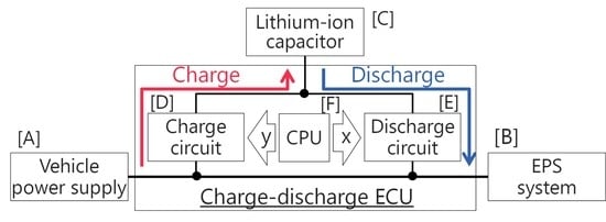
Figure 4 shows a block diagram of the charge–discharge system. The system possesses a charge circuit [D] and a discharge circuit [E]. The central processing unit (CPU) of the charge–discharge controller monitors the 12 V power supply and EPS. The CPU controls the discharge circuit to boost the power supply voltage by connecting the lithium-ion capacitor in series with the 12 V power supply (x) when the EPS requires energy that is beyond the upper limit of the 12 V power supply. When the lithium-ion capacitor discharges and the cell voltage drops, the CPU controls the charge circuit to recharge the lithium-ion capacitor from the 12 V power supply (y).
As the number of lithium-ion capacitors connected in series is increased, the system output increases. Generally, a 12 V electronic circuit board has a performance of 24 V withstand voltage. Even if the capacitor is connected in series to the 12 V power supply and boosted, no problem occurs if the voltage is up to about 20 V.
Furthermore, because the lithium-ion capacitor has an average voltage of 3 V/cell, a 12V power supply can be obtained by connecting four capacitors in series. In this configuration, it is suitable as a backup power supply during a 12 V power supply failure. It contributes to the realization of AD Level 4 that requires complete failure operation of EPS including power supply failure [
12,
13].
Detailed circuit operation is shown in
Figure 5. If the power consumption of the EPS is low, such as for straight-line driving, the FETs 1 and 2 are closed and the EPS is operated only by the 12V power supply. When the EPS requires a large amount of power, such as for abrupt steering or stationary steering, FETs 1 and 3 are closed, and the lithium-ion capacitor is connected in series with the 12 V power supply. After the system operates and the capacitor voltage drops, the lithium-ion capacitor is recharged using FETs 4 and 5 and the coil. Recharging starts when the electric power demand of the EPS falls below the 12 V power supply limit. If a power supply failure occurs, the EPS is driven by the electric power of the lithium-ion capacitor by closing FETs 3 and 5. Also, if something goes wrong with the circuit, FET 6 is closed and the EPS is driven with the bypass circuit.
The energy amount design of the lithium-ion capacitor required by the system is explained using the power waveform when performing a continuous stationary steering test on a 3.5-ton class full-size vehicle shown in
Figure 6.
As described in the introduction, the 12 V power supply limit is approximately 1400 W, and the power required for 3.5-ton class stationary is approximately 2000 W. As the steering angle increases, the electric power demand of EPS increases. In the power waveform, the integrated value of a region (red area) in which the electric power demand of EPS exceeds the 12 V power supply limit is the required energy amount of the lithium-ion capacitor per 1 time of stationary steering. Assuming that the power shortage region (red area) is approximated as a triangle and the power assist time is approximately 1 s, the required energy amount of the lithium-ion capacitor is about 300 J. The required energy amount of the system is obtained by multiplying the number of times to guarantee the stationary steering, and as shown in the blue area of
Figure 6, it can be reduced by controlling to recharge as soon as the power demand of EPS falls below the 12 V power supply limit.
The system can be built with a very small amount of energy and number of cells, but since it is necessary to supply a large current of up to 120 A, the system can only be designed with capacitors. When building the system with a battery, it is necessary to have a very large capacity, most of which is not used.
4. Mechanism of High Power Output
The torque-assist delay phenomenon that occurs at the time of abrupt steering in EPS using brushless DC motor is described below with reference to the motor rotation speed and torque characteristic diagram (N–T characteristic diagram) shown in
Figure 7.
The N–T characteristic when the torque command value is constant is indicated by the solid line in
Figure 7. The dashed line is the upper limit of the electric power that can be supplied from the 12 V power supply.
When the motor is rotated with the torque command value set to a certain value, the rotation speed at the point (rated point A) intersecting the dashed line of electric power is the maximum rotation speed at which the commanded torque can be outputted.
If the command torque is increased to output the steering rack force required for a full-size vehicle, the rated point moves on the broken line of electric power from rated point A to rated point B as shown in
Figure 7 “X”. The maximum value of motor rotation speed that can output the command torque decreases as shown in
Figure 7 “Y”.
The output torque decreases in the region above this rotation speed. Since the steering force of the driver increases as EPS torque assist decreases, abrupt steering causes the steering wheel to become heavy, resulting in “torque-assist delay”.
When the capacitor voltage is added to the 12 V power supply using the auxiliary power supply system, the rated point moves from B to C, and motor rotation speed can be increased while maintaining the command torque. This is the same as EPS assist torque reinforcement under the abrupt steering situation.
5. Actual Vehicle Evaluation
Testing Method
The steering system of a full-size SUV (car weight 3.5-ton class) equipped with hydraulic power steering was replaced with rack assist type EPS equipped with a 600 W brushless DC motor. It could output the steering rack force up to 18 kN. The torque assist responsiveness of EPS to steering speed was evaluated by following two patterns. The results are shown in
Figure 8.
Steer with only 12 V power supply.
Steer with 12 V power supply + developed system
(lithium-ion capacitor 2 cells; voltage boost + 6 V).
The 12 V power supply alone could not meet the EPS power demand. This caused a “torque-assist delay” that made the steering wheel heavy during high-speed steering. On the other hand, the 12 V power supply with the developed system experienced no torque-assist delay; the electric power shortage of the 12 V power supply was compensated by the electric power supplied from the lithium-ion capacitor.
Lowering the power-assist threshold from the lithium-ion capacitor reduces the load on the 12 V power supply required to operate the EPS. This “peak cut function” is useful to prevent battery overload degradation in situations where some electrical components require large power demands.
Next, we compared the steering force change with the 12 V power supply shut down while driving with and without the development system equipped with four series-connected 500 F lithium-ion capacitors (total energy amount was 9600 J). The results are shown in
Figure 9.
In a situation where the EPS was operated by a 12 V power supply alone, shutting down the 12 V vehicle power significantly changed the steering force and driving could not be continued. In a situation where the EPS was driven by a 12 V power supply and the developed system, even with the 12 V power supply shut down, the steering force was stable enough that the driver could not detect it.
The amount of time the developed system can sustain EPS power varies depending on the steering situation. In a steady circular turning with a radius of 10 m, it was driven for 3 min or more with four lithium-ion capacitors having a capacitance of 500 F. The reason is that, as shown in
Figure 10, the backup power supply voltage can maintain 12 V or more. This test result is considered to be enough time for the vehicle to stop safely on the roadside after the driver detects a power failure.
In addition, in order to make it easier for the driver to notice a shutdown of the 12 V power supply, an EPS control was developed to gradually reduce the steering assist force. This system is suitable for autonomous vehicle required redundancy of a power supply system and is a highly safe system.
To mount the developed system with no cooling–heating device in a vehicle, the improvement of the operating temperature range of the lithium-ion capacitor was essential. Conventional capacitors have only a temperature range of about −20 to 60 °C and cannot withstand the temperature requirement of the passenger compartment of a vehicle (−40 to 85 °C). Since the addition of a cooling–heating device makes the system larger, heavier, less efficient, and expensive, the developed system could hardly be installed to a vehicle. As a result, JTEKT improved the operating temperature range of the lithium-ion capacitor.
6. Adaptation of Electrical Power Storage Device in Vehicle Environment
6.1. Lithium-Ion Capacitor
The structure combines the positive electrode of an electric double layer capacitor, and the negative electrode and electrolyte solution of a lithium-ion secondary battery [
14,
15]. It is an electricity storage device with improved volumetric energy density that maintains the advantages of an electric double layer capacitor capable of instantaneously supplying and regenerating large amounts of power. It is expected to be used in various industries as well as automotive [
16].
6.2. Development of High-Heat-Resistant Lithium-Ion Capacitor
Through research and testing, the phenomenon that occurs at temperatures higher and lower than the operating temperature range of conventional products was identified, and how that contributes to the deterioration of the lithium-ion capacitor performance.
With high temperature, there was an increase of internal resistance and capacitance reduction proceeded irreversibly with the thermal decomposition of the electrolyte solution. The generation of decomposition gas causes cell expansion and eventually the cell ruptures. It has been found that the decomposition of electrolyte solution is due to the thermal decomposition of lithium hexafluorophosphate (LiPF6), which is a popular electrolyte used in lithium-ion capacitors and lithium-ion batteries.
With low temperature, output reduction with increase of internal resistance occurs reversibly. When the temperature was lowered to −20 °C or less, the electrolyte solution was frozen and the capacitor could not be charged/discharged. The negative electrode of a lithium-ion capacitor utilizes a chemical reaction during charge/discharge. The chemical reaction rate depends on temperature so an output reduction occurs on the low-temperature side.
From the above results, it was found that primarily an improvement of the electrolyte solution was necessary in order to extend the operating temperature range of the lithium-ion capacitor.
7. Implementation Items
Table 1 shows implementation items. The electrolyte salt LiPF
6, which caused thermal decomposition of the electrolyte at high temperatures, was changed to high-heat-resistant lithium compound salt (imide-based lithium-compound salt). Next, the composition ratio of the electrolyte solvent was reviewed and changed to a unique carbonate-based composition that does not freeze at −40 °C or boil at 100°C. Furthermore, in order to make the material perform properly, we adopted our proprietary method of selecting a capacitor material based on certain chemical rules.
8. Test Specimen and Testing Method
8.1. Test Specimen
A sheet of activated carbon coated on aluminum foil was used as a positive electrode. A sheet of graphite coated on copper foil was used as a negative electrode. The positive electrode and the negative electrode were alternately stacked via a separator. Three types of lithium-ion capacitors (capacitance 500 F, operating voltage 2.2 to 3.8 V) shown below were prepared.
Conventional capacitor using electrolyte solution in which 1.0 mol/L of LiPF6 was dissolved
(ethylene carbonate (EC):ethyl methyl carbonate (EMC):dimethyl carbonate (DMC) = 3:4:3)
Change only electrolyte solution
Change electrolyte solution and JTEKT proprietary method
8.2. Heat Resistance Evaluation
The high-temperature endurance test of lithium-ion capacitors was based on “High temperature continuous rated voltage application test” in IEC 62813-2015: Test method for lithium ion capacitors for electrical and electronic devices—Electrical characteristics. A 3.8 V float charge test was conducted with an ambient temperature of 85 °C. The standard requires that the internal resistance increase rate after the float-charging test 1000 h is 50% or less, and the capacitance reduction ratio is required to be 20% or less.
8.3. Evaluation of Large Current Charge–Discharge Properties
The resistance to high current charge–discharge of the developed capacitor was investigated. The performance deterioration of the capacitor was confirmed by charge–discharge cycle test in which the maximum temperature was changed from 85 to 110 °C in steps of 5 °C. The upper voltage of the capacitor was changed stepwise from 3.6 to 3.8 V. The charge–discharge rate was 900 C, CC/CV mode, and 10,000 cycles were performed.
After the cycle test, internal resistance and discharge capacity were measured according to IEC 62813-2015, and test threshold was set to performance degradation of approximately 10% or more.
8.4. Low-Temperature Properties Evaluation
The internal resistance rise multiple in a low-temperature environment was investigated based on internal resistance at 25 °C. The measurement method conforms to IEC 62813-2015.
The charge–discharge cycle performance at −40 °C of the developed capacitor was also investigated. Capacitor voltage range was 2.2–3.8 V, CC/CV charge–discharge mode, and charge–discharge rate was 85 C. Before checking the capacitor performance, the capacitor temperature was returned to 25 °C. Internal resistance and discharge capacity were confirmed in accordance with IEC 62813-2015.
9. Results
9.1. Heat Resistance Evaluation
The results are shown in
Figure 11. In the conventional capacitors, deterioration of both the capacity retention rate and internal resistance increase rate were remarkable. The required value was lowered about 100 h after the start of the test. The test was interrupted due to remarkable cell expansion from the decomposition of the electrolyte into gas triggered by the thermal decomposition of LiPF
6 [
17].
The capacitor with only the electrolyte liquid was improved in capacity retention rate and eliminated the cell expansion. However, the internal resistance increase rate was not improved.
The capacitor with electrolyte change and JTEKT proprietary method continued to meet the required values of capacity retention rate and internal resistance increase rate even after the float charge test was over the 1000 h specified in the standard. [
18]
From the above results, in order to improve the heat resistance of the lithium-ion capacitor, it is necessary to devise not only the improvement of heat resistance of constituent materials but also the selection of material for sufficiently exhibiting the performance of each material.
9.2. Evaluation of Large Current Charge–Discharge Properties
The results are shown in
Table 2 and
Table 3. By limiting upper voltage of the capacitor from 3.8 V to 3.6 V, the capacitor performance hardly changed even at 100 °C. It should be noted that the improvement of heat resistance of the capacitor also contributes to suppression of deterioration due to self-heating when large current charge–discharge is repeated.
9.3. Low-Temperature Properties Evaluation
The measurement result of internal resistance is shown in
Figure 12. The conventional capacitor could not be charged and discharged at −30 °C or less due to freezing of the electrolyte solution. In contrast, the developed capacitor could be charged and discharged even at −40 °C. The internal resistance was almost the same as the conventional one at −20 °C.
The result of the charge–discharge cycle test at −40 °C is shown in
Figure 13. The developed capacitor showed a slight deterioration in performance even after 200,000 cycles of testing. Not only at high temperature but also at low temperature, it has been confirmed that a large current supply, which is an advantage of the capacitor, is possible.
10. Conclusions
The newly developed auxiliary power supply system for EPS can eliminate the power shortage when mounting the EPS on a large vehicle without reinforcing the entire vehicle power supply. In addition, the developed system has excellent functional expandability, and can be operated as a redundant power supply in the event of a vehicle power failure or temporary blackout. It will support the realization of autonomous vehicles that require higher levels of safety.
In addition, the lithium-ion capacitor whose operating temperature range has been expanded helps to realize a system that can be mounted on a vehicle without a cooling–heating device. It expands the field of utilization not only in automobiles but also in various industrial fields.
Author Contributions
Data curation, K.I. and T.H.; Investigation, N.O., Y.K., K.I., F.S., and S.S.; Methodology, T.M., Y.K., Y.K., F.S., and T.H.; Project administration, T.M., T.S. (Toyoki Sugiyama), and K.N.; Software, F.S.; Supervision, K.N.; Validation, Y.K., N.O., T.S. (Tomoki Suganuma), S.M. (Shun Maruyama), and S.S.; Writing—original draft, T.M.; Writing—review & editing, K.N.
Funding
This research received no external funding.
Conflicts of Interest
The authors declare no conflict of interest.
References
- Japan Prime Minister’s Office; Advanced Information and Telecommunications Network Society Promotion Strategy Headquarters (IT Comprehensive Strategy, Headquarters). Public-Private ITS Concept Road Map. 2018. Available online: http://www.kantei.go.jp/jp/singi/it2/kettei/pdf/20180615/siryou9.pdf (accessed on 10 May 2019).
- SAE. Automated Driving Levels of Driving Automation are Defined in New SAE International Standard J3016. Available online: http://www.sae.org/misc/pdfs/automated_driving.pdf (accessed on 10 May 2019).
- ISO 26262. Road Vehicles Functional Safety; ISO: Geneva, Switzerland, 2011. [Google Scholar]
- IEC 61508-6. Functional Safety of Electrical/Electronic Programmable Electronic Safety-Related Systems, Annex B; IEC: Geneva, Switzerland, 2010. [Google Scholar]
- Kaneko, T.; Nakamura, H.; Fukasawa, R. Safety design for Automated Driving Systems. JARI Res. J. 2016, 2016, 20161003. [Google Scholar]
- Murata, M. Jtekt’s Perspective On Steering Systems for Autonomous Driving. Automotive Mirai Summit Spring, Tokyo, Japan, 11 April 2019. [Google Scholar]
- Ohashi, M. 2-Drive motor control unit for electric power steering. Denso Tech. Rev. 2016, 21, 48–53. [Google Scholar]
- Fuji Keizai Management Co., Ltd. Business Technology Office. Latest Trend of 48V Conversion for Vehicle Power Supply; Fuji Marketing Report; Fuji Keizai Management Co., Ltd. Business Technology Office: Tokyo, Japan, 2014; Volume 76. [Google Scholar]
- Miyazaki, H. Future views on EPS system technological development. JTEKT Eng. J. 2012, 1009, 19–22. [Google Scholar]
- Shinoda, S.; Higashi, M.; Sugiyama, T. Development of Auxiliary Power Supply System for Electric Power Supply Steering. In Proceedings of the JSAE Annual Congress (Spring) Proceedings, Yokohama, Japan, 21–23 May 2014; p. 20145065. [Google Scholar]
- Sato, F.; Higashi, M.; Sugiyama, T. Development of Auxiliary Power Supply System for Electric Power Supply Steering. In Proceedings of the JSAE Annual Congress (Spring) Proceedings, Yokohama, Japan, 20–22 May 2015; p. 20155307. [Google Scholar]
- Hibino, T.; Sato, F.; Shinoda, S.; Sugiyama, T. Auxiliary Power Supply System for Electric Power Supply Steering. In Proceedings of the JSAE Annual Congress (Spring) Proceedings, Yokohama, Japan, 23–25 May 2018; p. 20180195. [Google Scholar]
- Kaji, R. ISO 26262 Compliant and Redundant Design of Electric Power Steering (EPS), MONOist Automotive Forum; ISO: Geneva, Switzerland, 2015. [Google Scholar]
- Tanizaki, H.; Matsui, K.; Tasaki, S.; Ando, N.; Hato, Y.; Shibutani, H. Development of Lithium-ion Capacitor (3). In The 47th Battery Symposium in Japan Proceedings; ESJ: Tokyo, Japan, 2006; p. 3E04. [Google Scholar]
- Tasaki, S.; Tanisaki, H.; Miyakawa, R.; Shirakami, A.; Taguchi, H.; Matsui, K.; Ando, N.; Hatozaki, O.; Hato, Y.; Shibuya, H. Development of Lithium-ion Capacitor (4). In The 47th Battery Symposium in Japan Proceedings; ESJ: Edogawa-ku, Tokyo, Japan, 2006; p. 3E05. [Google Scholar]
- Miyakawa, R.; Hato, Y.; Inagawa, M.; Inoue, K.; Seki, D. Development of High-Power Lithium-Ion Capacitor. NEC Tech. Rep. 2010, 63, 70–74. [Google Scholar]
- Aurbach, D.; Zaban, A.; Ein-Eli, Y.; Weissman, I.; Chusid, O.; Markovsky, B.; Levi, M.; Levi, E.; Schechter, A.; Granot, E. Recent studies on the correlation between surface chemistry, morphology, three-dimensional structures and performance of Li and Li-C intercalation anodes in several important electrolyte systems. J. Power Sources 1997, 68, 91–98. [Google Scholar] [CrossRef]
- Takumi, M.; Komatsubara, Y.; Naoki, O.; Kimoto, Y.; Kentaro, I.; Nishi, K. Development of high heat-resistant Lithium-ion Capacitor. In Proceedings of the JSAE Annual Congress (Spring) Proceedings, Yokohama, Japan, 23–25 May 2018; p. 20180194. [Google Scholar]
© 2019 by the authors. Licensee MDPI, Basel, Switzerland. This article is an open access article distributed under the terms and conditions of the Creative Commons Attribution (CC BY) license (http://creativecommons.org/licenses/by/4.0/).

 ,
, 


