Article

A Method for 5G–ICN Seamless Mobility Support Based on Router Buffered Data

1
National Network New Media Engineering Research Center, Institute of Acoustics, Chinese Academy of Sciences, No. 21, North Fourth Ring Road, Haidian District, Beijing 100190, China
2
School of Electronic, Electrical and Communication Engineering, University of Chinese Academy of Sciences, No. 19(A), Yuquan Road, Shijingshan District, Beijing 100049, China
*
Author to whom correspondence should be addressed.
Future Internet 2024, 16(3), 96; https://doi.org/10.3390/fi16030096
Submission received: 19 January 2024 / Revised: 16 February 2024 / Accepted: 18 February 2024 / Published: 13 March 2024

Abstract

:
The 5G core network adopts a Control and User Plane Separation (CUPS) architecture to meet the challenges of low-latency business requirements. In this architecture, a balance between management costs and User Experience (UE) is achieved by moving User Plane Function (UPF) to the edge of the network. However, cross-UPF handover during communication between the UE and the remote server will cause TCP/IP session interruption and affect continuity of delay-sensitive real-time communication continuity. Information-Centric Networks (ICNs) separate identity and location, and their ability to route based on identity can effectively handle mobility. Therefore, based on the 5G-ICN architecture, we propose a seamless mobility support method based on router buffered data (BDMM), making full use of the ICN’s identity-based routing capabilities to solve the problem of UE cross-UPF handover affecting business continuity. BDMM also uses the ICN router data buffering capabilities to reduce packet loss during handovers. We design a dynamic buffer resource allocation strategy (DBRAS) that can adjust the buffer resource allocation results in time according to network traffic changes and business types to solve the problem of unreasonable buffer resource allocation. Finally, experimental results show that our method outperforms other methods in terms of average packet delay, weighted average packet loss rate, and network overhead. In addition, our method also has good performance in average handover delay.

1. Introduction

With the rapid development of mobile internet and the Internet of Things (IoT), as well as the widespread popularity of smart terminals, the types and quantities of mobile services have exploded, and mobile users’ demand for future networks has further increased. The rise of emerging applications such as the IoT and streaming media has triggered a rapid increase in data traffic, prompting an explosive increase in the amount of data transmitted over the network [1]. Ericsson’s mobile market report released in 2023 pointed out that in the next few years, the annual growth rate of mobile data traffic is expected to remain between 20–30%, and so mobile data traffic will continue to rise [2]. In order to cope with the explosive growth of mobile data traffic and large-scale device connections, as well as to adapt to emerging services and application scenarios, 5G came into being [3].
In order to meet the challenges of 5G low-latency business requirements, the 5G core network adopts the Control and User Plane Separation (CUPS) architecture. Under the CUPS architecture, the User Plane Function (UPF) can sink to the edge of the network. By deploying UPF in a distributed manner close to the base station, traffic localization can be achieved, data processing within the network can be supported, and end-to-end latency can be effectively reduced to achieve a balance between management costs and user experience. Consider the communication scenario between a User Equipment (UE) and a remote server. When the UE switches across UPFs, the UE’s network address will change. However, in the current TCP/IP network architecture, the change of IP address will cause the TCP/IP session to be interrupted. TCP/IP reconnection will seriously affect the continuity of delay-sensitive real-time services.
Information-Centric Networking (ICN) [4,5,6] is an emerging future network architecture. Different from the traditional TCP/IP network architecture, ICN takes information as the center of communication and separates identity and location. ICN’s identity-based routing can naturally support mobility, support in-network caching and multicast, and can achieve more efficient and timely content delivery [5]. Integrating ICN with 5G networks is of great benefit to solving delay-sensitive business continuity. Currently, the industry is exploring 5G and ICN deployment solutions, and ICN can be integrated into Data Network (DN) [7]. Indeed, while ICN as a solution integrated with 5G brings some advantages in handling mobility, the current 5G-ICN fusion solutions have not fully exploited the benefits of ICN in addressing real-time business continuity issues related to changing addresses. There is still research space for optimizing switch paths and reducing packet loss during handover.
We roughly divide seamless mobility methods in ICN into three categories, namely broadcast/multicast-based methods, active caching-based methods, and temporary buffer-based methods. When the network loses the location of mobile producers, broadcast/multicast-based methods [8,9,10] achieve seamless mobility support by finding mobile producers through multicast/broadcast interests. In larger, denser network environments, multicast/broadcast interests can incur significant network overhead. Broadcast/multicast-based methods [11,12,13,14,15,16,17] use an active caching method to minimize Interest retransmission during handover. These methods assume that the data already exist and proactively push future requests to the network cache before handover. However, this is not the case in real-time communication. Most real-time data (e.g., online gaming, internet phone calls, video conferencing, etc.) are data that are generated and delivered immediately upon request. Therefore, active caching approaches cannot provide seamless mobility support for real-time applications. Temporary buffer-based methods [18,19,20,21,22] minimize packet loss during handover by buffering packets for a period of time on the access device. LPBMMS [21] uses location prediction technology combined with data buffering to bring better handover performance. However, the existing ICN seamless mobility support solution based on data buffering lacks management of buffered data and cannot distinguish mobile business types, resulting in unreasonable allocation of buffering resources. Different types of businesses have different requirements for packet loss. In video communication and streaming media applications, especially real-time video conferencing or online live broadcast, business continuity and real-time are particularly important for mobile user performance experience. When buffering resources are limited, how to effectively allocate buffering resources to different types of mobile data flows is an urgent problem to be solved. The quality of buffer resource allocation will directly affect users’ Quality of Experience (QoE).
This paper integrates 5G with ICN, takes advantage of router data buffering capabilities, and designs a seamless mobility support method based on router buffered data suitable for real-time applications to improve the QoE of mobile users. The main contents of this article are as follows:
  • Referring to the 5G-ICN architecture in [7], we propose a seamless mobility support method based on router buffered data (BDMM), which fully utilizes the identity-based routing capabilities of ICN to solve the problem of UE cross-UPF handover affecting business continuity. BDMM also uses the ICN router data buffering capabilities to reduce packet loss during handovers.
  • We design a dynamic buffer resource allocation strategy (DBRAS). This strategy comprehensively considers factors such as the status of the mobile buffer, the transmission rate of the mobile data flow, and the business category of the mobile data flow, and adjusts the buffer resource allocation results in a timely manner based on network traffic changes and business types to optimize the overall loss in performance of mobile data flows.
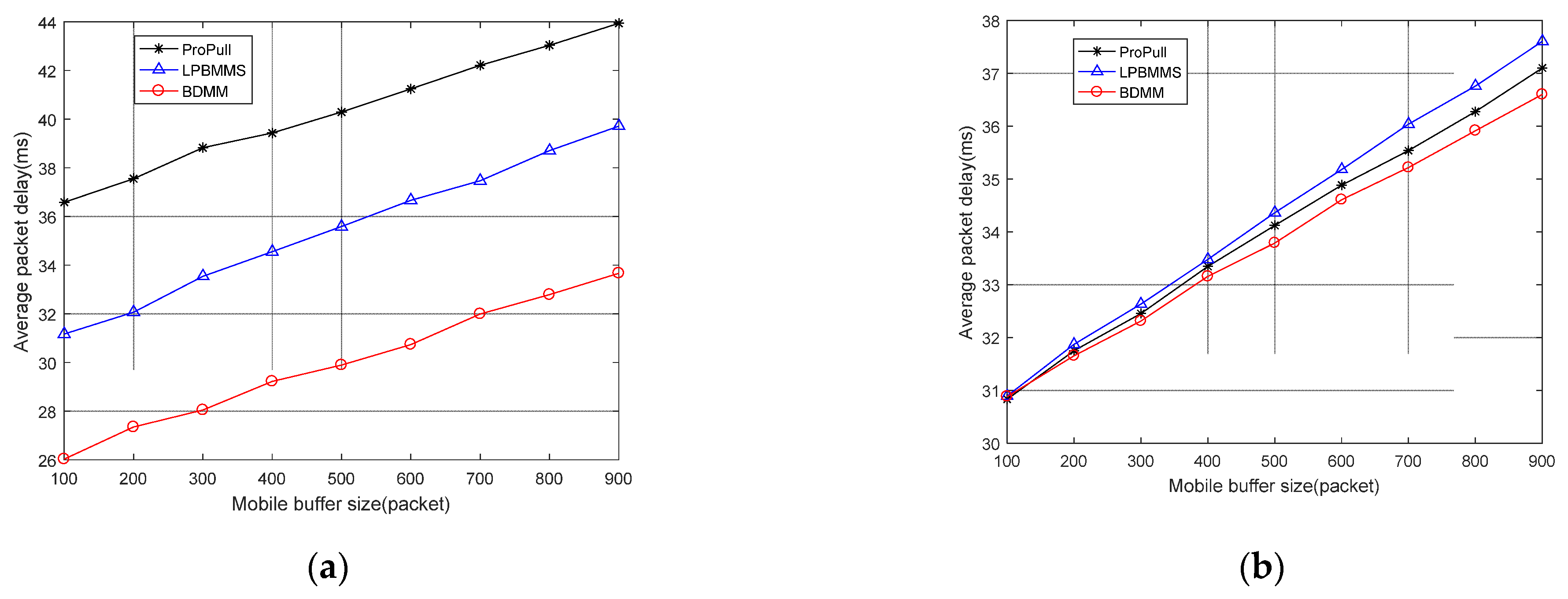
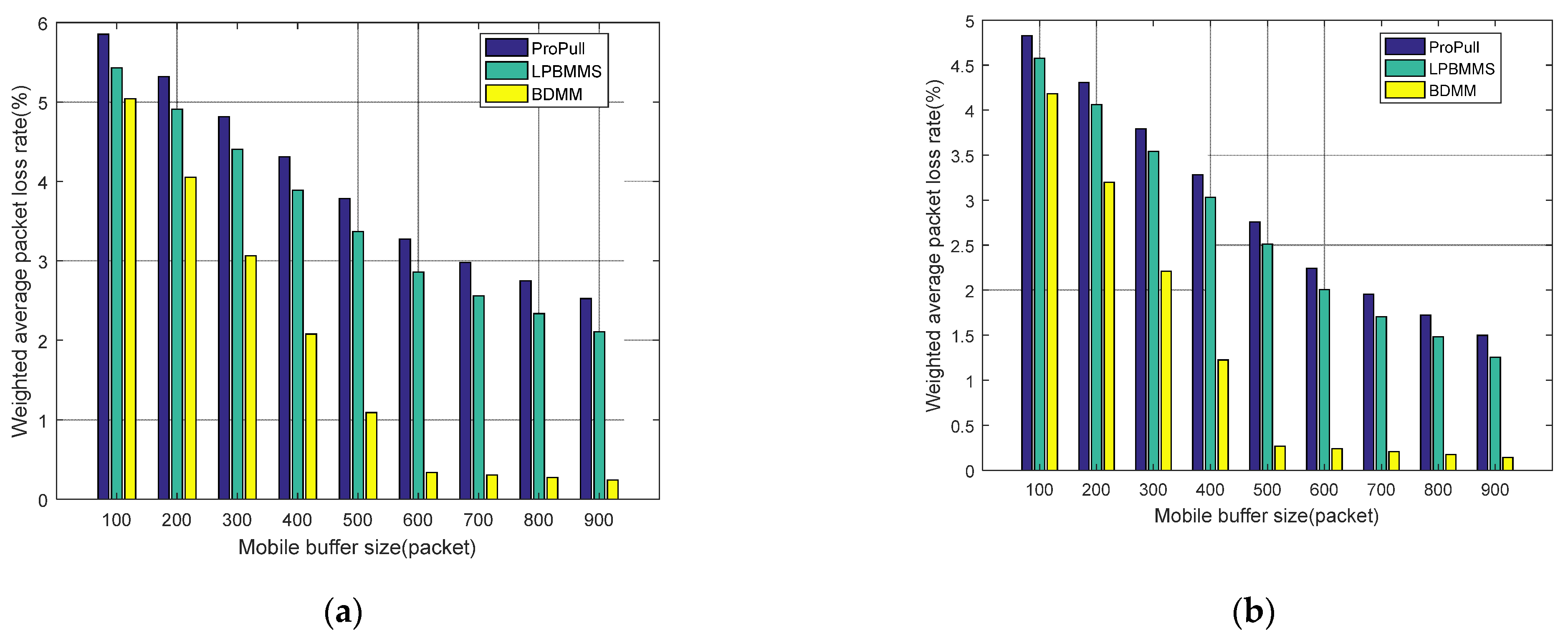
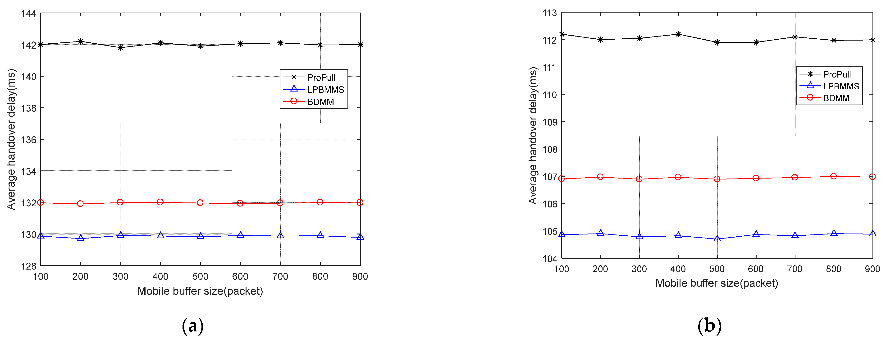
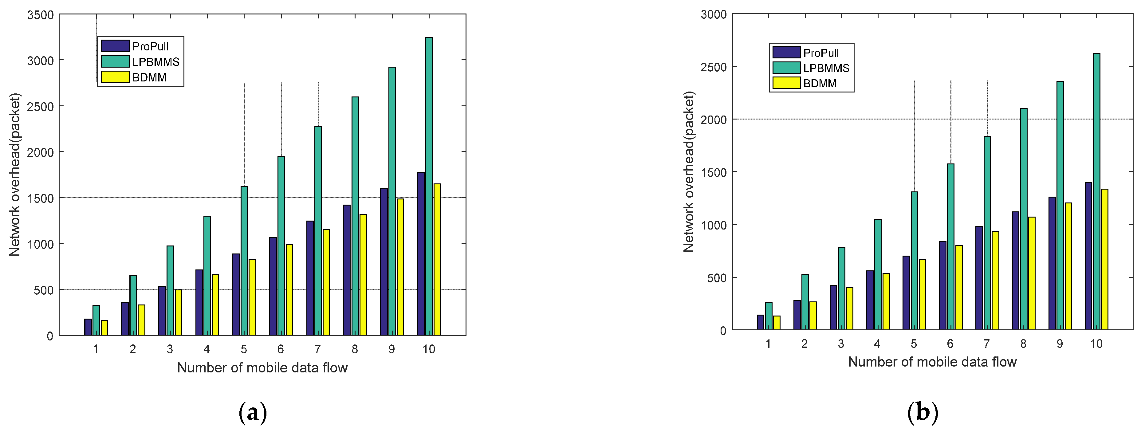
  • We conduct a series of experiments to evaluate the performance of the proposed method. Experimental results show that our method outperforms other methods in terms of average packet delay, weighted average packet loss rate, and network overhead. In addition, the proposed method also has good performance in average handover delay.
The rest of this paper is organized as follows. In Section 2, we review 5G-ICN network convergence research and research on seamless mobility support methods in ICN, respectively. In Section 3, we describe the proposed seamless mobility support method and describe the buffer resource allocation problem. In Section 4, we present the dynamic buffer resource allocation strategy. Section 5 discusses the experimental results of the proposed seamless mobility support method. Finally, we conclude the paper and discuss our plans for related future work in Section 6.

2. Related Work

In this section, we discuss the associated work of 5G-ICN network convergence and the related research on seamless mobility support in ICN.

2.1. 5G-ICN Network Convergence

The advantages of ICN are very consistent with the goals of 5G, so ICN has become one of the ideal architectures for 5G. Researchers generally focus on introducing ICN technology into the 5G network architecture to define a new solution that breaks through the limitations of traditional solutions. For the research on the integration of ICN with 5G, Ravindran et al. [7] extended the 5GC’s control plane and user plane to support Protocol Data Unit (PDU) sessions of endpoints in ICN, and provides an example of using ICN-enabled 5GC to handle session mobility. Existing research has shown that the integration of the ICN paradigm with Mobile Edge Computing (MEC) brings new opportunities and challenges to realize the 5G vision [23]. The great potential of ICN in 5G MEC, Software-Defined Network (SDN) and Network Function Virtualization (NFV) is discussed in [24]. The application of MEC, SDN and NFV can ensure mobile users’ QoE [25]. Internet Service Providers (ISPs) can provide customized multimedia streaming services to customers through SDN and NFV in future networks, and provide QoE that meets customer needs through intelligent QoE control and management methods [26]. In [27], the authors introduce a common QoE provisioning ecosystem and provide use case scenarios for emerging multimedia streaming services in software-based networks of 5G/6G and beyond. Kang et al. [28] considered integrating SDN with ICN and proposed an enhanced programmable data plane that supports ICN mobility to reduce handover latency. Zhao et al. [29] proposed a time period-based hybrid caching (TSBC) strategy based on 5G-ICN bearer network infrastructure. Researchers have tried using ICN-enabled forwarding equipment between the base station and the core network [30,31]. In [32], such equipment is used to enable ICN and adopt device-to-device communication in 5G.
Referring to the LTE architecture [33] and related research [34], 5G and ICN deployment solutions have been explored. Through research and analysis, the current deployment solutions mainly have three models, namely overlay model, integrated model and flat model. In the overlay model, ICN operates as a supplementary service layered atop the existing IP infrastructure. Even in overlay configurations, ICN can act as a managed services platform under operator control, delivering caching and computing benefits through edge and core cloud infrastructure. In the integrated model, there exists a distinct control management plane that serves as a relay for Protocol Data Units (PDUs) transmitted via 5G as a carrier from the UE to the gateway hosting the ICN functionality. This model offers the advantage of utilizing the signaling and control layer infrastructure already established in LTE networks, while also enabling cache distribution within the core infrastructure situated closer to the UE. In the flat model, 5G-ICN is integrated into the network to incorporate key control functions such as Mobility Management Entity (MME), Home Subscriber Service (HSS), and Policy and Charging Rules Function (PCRF) by enabling ICN functions. The above three deployment solutions of 5G and ICN converged networks, namely overlay, integrated and flat, are summarized here in terms of ease of deployment, economic cost and implemented functions, as shown in Table 1. It can be seen that the three models have their own advantages and disadvantages. The overlay model has the simplest architecture and the most flexible deployment. However, this model can only implement basic forwarding control separation and caching functions. Because the flat model takes advantage of the slicing function of the 5G network, it is relatively cost-effective and functionally complete, so it is widely used in the current 5G and ICN converged networks. Due to the completeness of its ICN function, the integrated model has also been applied by companies such as Cisco to study 5G and ICN converged networks in specific scenarios. In overlay model, this article considers the UPF sinking scenario.

2.2. Seamless Mobility Support in ICN

Seamless mobility methods in ICN can be roughly divided into three categories, namely broadcast/multicast-based methods, active caching-based methods, and temporary buffer-based methods. In the next section, we discuss these three types of methods in turn.
We first discuss broadcast/multicast-based methods. Ravindran et al. [8] utilized multicast technology to achieve seamless mobility support. When the producer (or consumer) switches, the old Point of Attachment (PoA) will transfer the same Interest (or data packet) which is forwarded to a potential PoA near the producer (or consumer). A hop-based forwarding strategy [9] was proposed to support seamless producer mobility. The key idea of this strategy is that the router decides whether to use the FIB entry to forward the Interest or to broadcast it, based on the number of hops the Interest has traveled. When the consumer finds that the producer is unreachable, the consumer resends the Interest and updates its hop count, causing the router to broadcast the Interest to find the producer. When the consumer receives the data packet responded to by the producer, the consumer re-updates the hop count of the Interest, and the Interest forwarding strategy is FIB forwarding. Kar et al. [10] proposed the neighborhood registration scheme. When a mobile producer moves from one Access Point (AP) to another, the solution is to register the mobile producer not only to the nearest AP, but also to multiple neighboring APs. When an AP detects that a producer has left, the Interest is forwarded to all neighboring APs. The data packets responded to after the mobile producer switches are used to update the FIB table to implement path updates. This approach effectively reduces delays caused by AP switching and lowers packet loss rates. Broadcast/multicast-based methods have problems such as potentially large broadcast/multicast range, high network resource usage, and high network overhead.
Next, we introduce the use of active caching technology to enhance ICN seamless mobility support. Vasilakos et al. [11] proposed the Selective Neighbor Caching (SNC) method, which improves seamless mobility by actively caching requests and corresponding content to a subset of proxies located one hop away from the proxy the mobile device is currently connected to. ProCacheMob [12] assumes that the request pattern is known, and actively pushes the content of future requests to the network cache before switching to satisfy the Interest at the time of switching. This scheme utilizes location predictors and data request patterns to cache data before handoffs occur. Essentially, ProCacheMob takes predicted future Interest that will be sent to mobile producers and caches their content before switching. Therefore, Interest retransmissions during producer movement are avoided. Furthermore, various caching strategies have been proposed to enhance ICN mobility support. PNPCCN [13] pushes content to the network cache based on content popularity. SCaN-Mob [14] minimizes the impact of mobile producer unavailability in NDN by creating Interest forwarding strategies and cache replacement strategies to achieve seamless switching of producer in wireless networks. In [15], the authors proposed a cooperative caching mechanism based on neighbor message propagation, making full use of the nodes on the forwarding path from the source AP to the destination AP to cache fresh and popular content at high-value nodes. In addition, in the field of Internet of Vehicles, active caching also plays a big role. AlNagar et al. [16] proposes a new active caching scheme that uses prior information of vehicle requirements and mobility patterns, considers RSU cooperation modes and non-cooperation modes, and minimizes communication delays in a vehicular ad-hoc network (VANET). In [17], the authors propose a framework in 5G and networks that are beyond heterogeneous to enhance support for mobile users’ QoE. The framework utilizes user mobility prediction, user preference inference and fine-grained resource reservation to improve overall user QoE through personalized data caching and dissemination in HetNet. These methods assume that the data already exist and proactively push future requests to the network cache before handover. For communication services that generate data in real time, active caching-based methods are not applicable.
In order to provide seamless mobility support, most methods based on temporary data buffering use the access device before handover or the access device after handover to buffer data packets for a period of time. Kim et al. [18] proposed an “Interest Forwarding” process to support producer mobility. The mobile producer’s Previous Access Router (PAR) buffers the Interest until it receives a virtual Interest from the producer. The PAR then forwards the buffered Interest to the producer. This solution recommends that the life cycle of real-time content is slightly larger than the handover delay (L2 handover delay + RTT/2) to support rapid recovery from packet loss caused by handover. In order to enhance seamless content source mobility support in mobile named Data Network environments, a new locator-based mobility support method is proposed [19]. Once an impending switch event is detected, the content source triggers PAR to buffer Interest destined for the content source until the forwarding update is completed and a new route is established to reach the content source’s current location. Furthermore, a study in [20] designed a producer mobility support scheme for real-time multimedia transmission. ProPull [20] focuses on providing continuous multimedia transmission and seamless services. For scenarios where subsequent content needs to be generated in real time, when the producer detects that a switch has occurred, the mobile producer sends a special packet to its connected access router to obtain the router name and trigger the access router buffering Interest before it switches. Once the producer completes the switch, it uses Propaganda Interest (PI) to pull the Interest from the old location to the new location. In addition to reactive data buffering, LPBMMS [21] uses location prediction technology and data buffering technology for anchor-free producer mobility management to support seamless handover. When the mobile producer’s received signal strength falls below a specific threshold, it sends an Interest Path Update message (INTEREST_PU) to the old Access Point (oAP) to signal its mobility. The oAP uses INTEREST_PU to predict the new Access Point (nAP) of the mobile producer, and then sends an Interest redirection (INTEREST_RED) to the nAP to redirect the Interest to nAP. Upon detecting the mobile producer connection, the nAP releases buffered Interests. If the nAP prediction fails, the mobile producer broadcasts its new name prefix, prompting the oAP to release buffered replica interests. In [22], the author proposes a new NDN link service called Producer Mobility Link Service (PMLS) to implement mobility support. PMLS is used to repair old links so that connectivity to the pNAR can be maintained, and this forces the previous router to buffer interests arriving during the move, forwarding them to the producer after the handover. However, these methods currently only focus on using the buffer resources on the access device to reduce packet loss during the handover, and lack specific design solutions for buffer resource allocation.

3. BDMM

In Section 3.1, we first present an overview of BDMM’s architecture. We describe how to achieve seamless mobility support in Section 3.2. Finally, the mobile buffer resource allocation problem statement is given in Section 3.3.

3.1. Architecture Overview

Operators can use ICN as DN and extend the 5G core network to provide session mobility support [7]. The advantage of ICN as a DN integrated with 5G is that ICN introduces name-based identities which are location-independent, and can handle host mobility very effectively by applying the application-bound identifier and name resolution split principle. ICN also allows content to be independently replicated at network nodes or propagated through ICN routers, thereby bringing benefits to high-bandwidth/low-latency applications (such as AR/VR). Referring to [7], our proposed seamless mobility support method adopts 5G-ICN architecture, which uses SEANet [35] in the DN and can achieve coexistence with existing IP networks. A central feature of our approach is the use of SEANet to support session mobility.
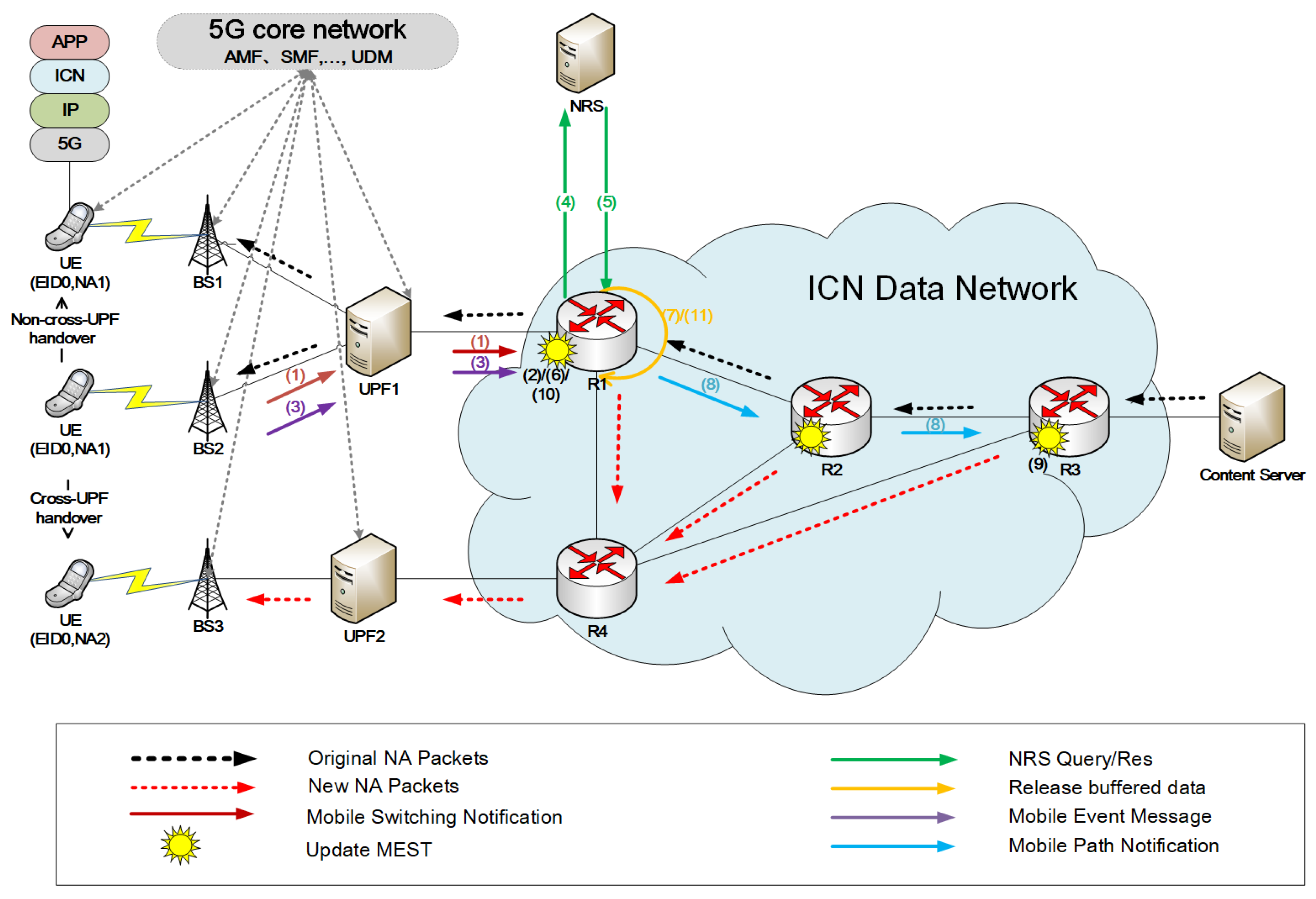
As shown in Figure 1, the UPF sinks to the edge of the network and is deployed in a distributed manner close to the base station (BS). In dense base station deployment scenarios, one UPF can connect multiple base stations. When the UE switches to the base station under the same UPF, the network address does not change. We define the above handover as a non-cross-UPF handover (as shown in Figure 1, the UE switches from BS2 to BS1). When the UE switches between base stations under different UPFs, the network address changes. We define the above handover as a cross-UPF handover (as shown in Figure 1, the UE switches from BS2 to BS3).
Following the basic principle of identity-location separation in ICN, each network entity is assigned an Entity-ID (EID) as an identifier (or name) and a Network Address (NA) as a locator. Entities such as content, devices, and services are considered network entities. In order to ensure compatibility with existing IP networks, the IP address is used as NA. The Name Resolution System (NRS) maintains a mapping between identifiers and locators. UE and ICN routers in the DN support identity-based ICN packet forwarding, and other network devices (BS, UPF, etc.) support IP packet forwarding. Considering the scenario where the UE requests the Content Server, the request packet has the same format as the data packet, and both need to carry the source EID (UE’s/Content Server’s identifier), destination EID (Content Server’s/UE’s identifier), source network address (UE’s/Content Server’s network address) and destination network address (Content Server’s/UE’s network address). We collectively refer to request packets and data packets as packets. In order to implement the dynamic buffer resource allocation strategy, the data packet also needs to carry the service type that identifies its business type. Referring to MobilityFirst [36], the function of the ICN router, which alters the destination address of packets based on the identification (destination EID), is identified as a late-binding function. We designate the ICN router executing late-binding processing as a late-binding node (LBN). The ICN router can locate the valid network address of the mobile entity in the Name Resolution System (NRS) using the identifier of the mobile entity.
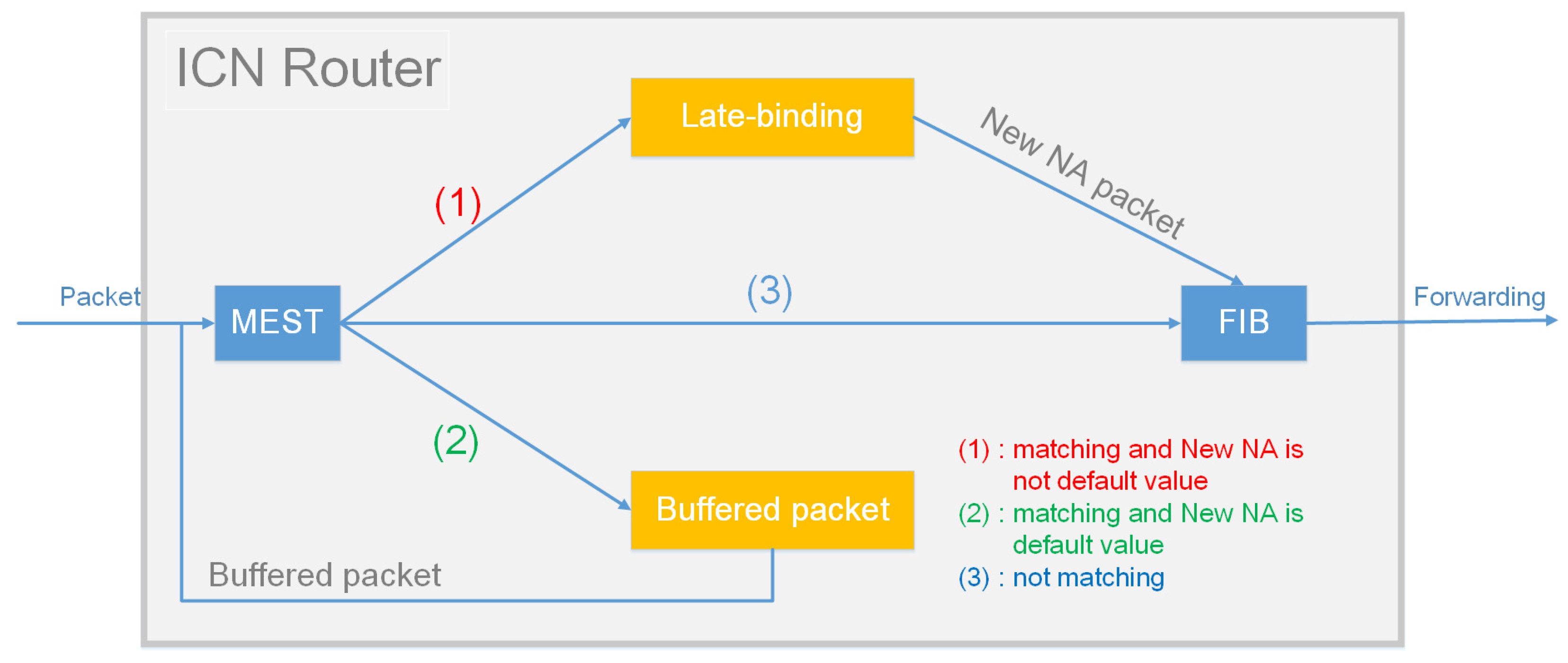
In order to implement packet buffering and packet redirection, each ICN router needs to provide a buffer and to maintain a Mobile Entity State Table (MEST), which consists of a set of Mobile Entity State Table Entries (MESTEs). Each MESTE includes the EID and the New NA (the latest network address of the EID or the default value). Figure 2 describes the process of ICN router forwarding packets. After receiving the packet, the ICN router first queries MEST based on the destination EID carried in the packet. If there is a matching MESTE and the New NA in the table entry is not the default value, the packet will be late-binding, that is, the destination network address in the packet will be replaced with the corresponding NA in the MESTE, and then the FIB will be matched for forwarding. If a matching MESTE exists and New NA in the table entry is the default, the ICN router will buffer the packet. If there is no matching MESTE, the ICN router will directly match the FIB for forwarding. When the ICN router releases the buffered packets, it will schedule the buffered packets in the buffer to enter MEST again to implement redirection of buffered packets.

3.2. How to Achieve Seamless Mobility Support?

As shown in Figure 1, assuming that the UE is initially connected to BS2, the UE continuously requests content published by the Content Server. Before the UE moves, the Content Server replies to the UE that the original packet forwarding path is Content Server → R3 → R2 → R1 → UPF1 → BS2 → UE. When the source BS (BS2) senses that the UE is about to switch, the source BS (BS2) sends a Mobile Switching Notification to the uplink UPF (UPF1) (step 1). The Mobile Switching Notification carries the UE’s identifier (EID0). The source UPF (UPF1) relays the Mobile Switching Notification to the uplinked access router (R1). After receiving the Mobile Switching Notification, the access router (R1) adds/updates the local MEST-related entry, sets the “EID” field of the entry to the UE identifier (EID0) and sets the “New NA” to the default value (Step 2). At this time, the access router (R1) will buffer the packets destined for the UE. The buffer resource allocation strategy used by the access router (R1) is as described in Section 4.
After the UE handover is completed, the source BS (BS2) senses the UE address change result, constructs and sends a Mobile Event Message to the uplink UPF (UPF1) (step 3). The Mobile Event Message needs to carry both the UE’s identifier (EID0) and the address change flag. The address change flag can be identified by “0” and “1”, indicating that the UE network address has not changed and that the UE network address has changed, respectively. The source UPF (UPF1) relays the Mobile Event Message to the uplinked access router (R1). If the access router (R1) receives the Mobile Event Message, it will determine its address change flag field. If this field is “1”, it proves that the UE has changed its address (referring to the scenario where the UE switches from BS2 to BS3, the UE performs cross-UPF handover). Then, the access router (R1) will query the NRS for the latest network address of the UE based on the UE’s identifier (EID0) carried in the Mobile Event Message (step 4). When the access router (R1) receives the response from the NRS, it learns the UE’s latest network address (NA2) (step 5). Next, the access router (R1) updates the local MEST-related entry and sets the “New NA” field of the entry corresponding to the UE’s identifier (EID0) to the UE’s latest network address (NA2) to redirect the packet to the UE’s latest location (step 6). The access router (R1) then releases the relevant buffered packets (step 7). The packet forwarding path is Content Server → R3 → R2 → R1 → R4 → UPF2 → BS3 → UE. The access router (R1) also constructs a Mobile Path Notification to propagate to the Content Server’s access router (R3) in the opposite direction to that of the original packet (step 8). The mobility path notification carries the UE’s identifier and the UE’s latest network address (NA2). After receiving the Mobile Path Notification, the intermediate router (R2) and the access router (R3) of the Content Server update the local MEST to achieve handover routing optimization (step 9). Finally, the optimized packet forwarding path is Content Server → R3 → R4 → UPF2 → BS3 → UE.
If the access router (R1) receives the Mobile Event Message with the address change field “0”, this proves that the UE has not switched to changing the address (referring to the scenario where the UE switches from BS2 to BS1, the UE performs non-cross-UPF handover). The access router (R1) will delete the relevant entries corresponding to EID0 in the local MEST (step 10). After that, the access router (R1) will no longer buffer packets. At the same time, the access router (R1) releases the relevant buffered packets (step 11). The packet forwarding path after switching is Content Server → R3 → R2 → R1 → UPF1 → BS1 → UE.
Our method utilizes the ability of ICN routers to forward packets based on identifiers to solve the problem of session interruption caused by UE cross-UPF handover in 5G networks. Our method also makes full use of the buffering packet capability of the ICN router to buffer packets during UE handover to achieve seamless handover. In addition, in the cross-UPF handover scenario, our method optimizes the handover path by propagating Mobile Path Notification.

3.3. Buffer Resource Allocation Problem Statement

Existing seamless mobility support solutions based on temporary data buffering only propose data buffering at the access devices (Access Point or access router), and do not clearly define the specific solution design for buffering resource allocation. When buffer resources are unlimited, all packets during handover can be buffered. However, in a real environment, there is an upper limit on the buffer resources of access network devices. Assume that the buffering resources of the access network devices have been consumed and the UE has not completed the handover. In this scenario, subsequent packets sent to the UE continue to arrive, and cannot be buffered. It is assumed that there are two different types of mobile data flows in the UE, such as real-time data flow and non-real-time data flow. If the mobile buffer only adopts the Complete Sharing (CS) strategy [37], the buffer resources will be allocated to the two data flows according to the rate of the data flow. When the real-time data flow rate is much lower than the non-real-time data flow rate, more buffer resources are allocated to the non-real-time data flow. This will result in the loss of a large number of real-time packets during the handover. Real-time services are sensitive to packet loss, and the loss of a large number of data packets will seriously affect the quality of mobile user experience.
From the above discussion, it can be seen that when there are multiple mobile data flows sharing buffer resources in the network, the buffer resource allocation strategy is related to multiple attributes of the mobile data flows. Therefore, when buffering resources are limited, how to allocate appropriate buffering resources to multiple mobile data flows is a major issue in seamless mobility support.

4. Dynamic Buffer Resource Allocation Strategy

In order to optimize the overall performance loss across all mobile data flows in the network, inspired by literature [38,39], we designed a dynamic buffer resource allocation strategy (DBRAS). This strategy comprehensively considers three factors: the status of the mobile buffer, the transmission rate of the mobile data flow, and the business category of the mobile data flow.
Referring to [39], we divide a buffer with fixed resources into G virtual partitions according to the business type. We define V P i as the i -th virtual partition, and define T i as the threshold of V P i . If B is the total buffer resource and G is the total business category, then B = i = 1 G T i . The threshold T i is related to different types of business traffic and business priorities, so T i is redefined as shown in Formula (1).
T i = θ i × B j = 1 G θ j
In the Formula (1), θ i is the coefficient of virtual partition V P i , which follows Pareto distribution. The calculation formula of θ i is as follows.
θ i = ( p r i o r i t y i ) 2 × p e r c e n t i
Among them, p r i o r i t y i ( 0 < p r i o r i t y i 1 ) is the priority of the i -th type of business traffic. For the highest priority category, the priority is equal to 1. p e r c e n t i is the proportion of the i -th type of business traffic.
Business traffic changes dynamically over time, so virtual partition thresholds need to be updated regularly. It can be seen from Formula (2) that we need to regularly calculate the proportion of different types of business traffic. Let S i , n represent the number of packets received by the i -th virtual partition in the n -th statistical period. The formula for calculating the proportion p e r c e n t i , n of the i -th type of business traffic in the n -th statistical period is:
p e r c e n t i , n = S i , n j = 1 G S j , n
In the mobile buffer, we create a buffer queue for each mobile data flow. Virtual partition V P i maintains information related to the buffer queue of mobile data flows belonging to business type i . q i , 1 , q i , 2 , , q i , F is the buffer queue set in virtual partition V P i , and q i , k is the identifier of the buffer queue of the mobile data flow F l o w k in the virtual partition V P i . This identifier can be jointly identified by the source EID and destination EID of the mobile data flow. The buffer queue information includes its length, the total number of received packets, and the total number of discarded packets. l i , k is the length of the buffer queue q i , k . σ i , k is the total number of packets received by the buffer queue q i , k . d i , k is the total number of packets dropped by the buffer queue q i , k . The total queue length Q i of virtual partition V P i is calculated by Formula (4).
Q i = k = 1 F l i , k
Assuming Q is the total queue length of G virtual partitions, then the Q calculation formula is as follows.
Q = i = 1 G Q i
DBRAS is related to the status of the mobile buffer. After receiving the packet, the mobile buffer decides whether to buffer the packet based on the current status. If Q < B, we call the buffer state the allowed state, and the packet is allowed to be added to the buffer. If QB, we call it a diagonal state, and a replacement or discard operation will occur.
Q < B ,   a l l o w   s t a t u s Q B ,   d i a g o n a l   s t a t e
To implement dynamic resource allocation strategies, a set of primitive operations is defined. At any time, the basic operations that can be taken include join operations, replace operations, and drop operations. Typically, such an action can be taken at any time. However, due to the memoryless nature of arrival and service times, in the absence of losses we assume that actions are taken only upon arrival or departure.
(1) Join operation: Use the source EID and destination EID of the arriving packet to jointly query whether the corresponding buffer queue exists in the corresponding virtual partition. If there is a corresponding buffer queue, insert it directly into the tail of the corresponding queue. If there is no corresponding buffer queue, a new buffer queue is created. Then update the relevant status value of the buffer queue.
(2) Replacement operation: Drop a packet from the end of a selected buffer queue; next, add the arriving packet to the buffer. Then update the relevant status value of the buffer queue.
(3) Discard operation: Discard the packet that has just arrived. If there is a corresponding buffer queue, the relevant status value needs to be updated.
The dynamic buffer resource allocation strategy is shown in Algorithm 1. When the mobile buffer receives the incoming packet belonging to the mobile data flow F l o w A , it first finds its business type I according to the service type field carried by the packet and updates S I , n . Next, use Formulas (4) and (5) to calculate the total queue length of all virtual partitions. Then use Formula (6) to determine the current mobile buffer status. When the buffer state is in the allowed state, the incoming packet is allowed to join the virtual partition V P I and perform the joining operation. If the buffer state is in a diagonal state, it is necessary to determine whether the total queue length Q I of the virtual partition V P I exceeds its threshold T I . If the total queue length Q I of the virtual partition V P I does not exceed its threshold T I , a replacement operation is required. Find the virtual partition V P J whose total queue length exceeds the threshold and has the lowest priority. In order to ensure packet loss fairness among multiple data flows belonging to the same type, the buffer queue q J , K with the smallest packet loss rate is selected from the virtual partition V P J for replacement operation. If the total queue length Q I of the virtual partition V P I exceeds its threshold T I , the discard operation is performed. Assuming that there are G business types, that is, there are G virtual partitions, and each virtual partition has F data flows, then the algorithm complexity of DBRAS is O ( G F + G + 2 F ) .
Algorithm 1 Dynamic Buffer Resource Allocation Strategy
Input: incoming packet, q i , k , l i , k , d i , k , σ i , k , Q i , S i , n , B, i = 1 G ,   k = 1 F
Output:  q i , k
1:        for each incoming packet do
2:          Find the business type I of the incoming packet
3:           S I , n = S I , n + 1
4:          calculate Q i by Equation (4)
5:          calculate Q by Equation (5)
6:          if  Q < B  then
7:             if q I , a  then
8:               The incoming packet is inserted into the q I , A
9:             else
10:              Create a new queue q i , a and insertthe incoming packet
11:            l I , A = l I , A + 1 , σ I , A = σ I , A + 1
12:           end if
13:       else
14:           if    Q I < T I   then
15:              Find the lowest priority overlimit V P J
16:               q J , K = a r g m i n J , k { d J , k σ J , k }
17:              discard a packet at the end of the q J , K
18:               l J , K = l J , K 1 , d J , K = d J , K + 1
19:              goto 7
20:           else
21:              drop the incoming packet
22:              if   q I , A  then
23:                 d J , K = d J , K + 1
24:           end if
25:       end if
26:     end for

5. Performance Evaluation

In this section, we perform a series of experiments to assess the effect of our proposed approach on the performance experience of mobile users. We use four performance indicators, including average packet delay, weighted average packet loss rate, average handover delay and network overhead. We developed the proposed mobility support method and the proposed dynamic buffer resource allocation strategy on Mininet [40], and we also implemented ProPull [20] and LPBMMS [21]. ProPull [20] and LPBMMS [21] both adopt the Complete Sharing (CS) strategy [37], in which ProPull sets the mobile buffer at the old access router before handover, and LPBMMS sets the mobile buffer on the source base station before handover and the predicted target base station, respectively. The default LPBMMS position prediction success probability is 50%.

5.1. Performance Evaluation Indicators

Average packet delay: Referring to [41], the average packet delay is the average difference between the time the UE receives a packet at its new location after moving and the time the Content Server sends the packet.
Weighted average packet loss rate: To evaluate the overall packet loss rate of different types of mobile data flows, we introduce the weighted average packet loss rate. The calculation formula of the weighted average packet loss rate is shown in Formula (7), where w i is the weight of the mobile data flow, and w i can be the priority of the business type of the mobile data flow. P L i is the packet loss rate of mobile data flow i , which is the ratio of the total number of packets of data flow i received by the UE at the new and old locations relative to the total number of packets of data flow i sent by the Content Server.
P L ¯ = i = 1 F w i × P L i i = 1 F w i
Average handover delay: Referring to [42], we define the average handover delay as the average handover delay of multiple mobile data flows on the UE. We also define handover delay of mobile data flow i as the difference between the time when the UE receives the first packet of mobile data flow i at the new location and the time when the UE receives the last packet of mobile data flow i at the old location.
Network overhead: The amount of mobile buffer resource required to buffer all packets during the handover.

5.2. Experiment Setup

The experimental platform includes Mininet, OpenvSwitch and Ryu [43] controllers. This section uses Mininet to create the network topology. Considering that there may be multiple handover paths after UE mobility handover, this article simulates a multi-path network topology, as shown in Figure 3. We use OpenvSwitch to simulate routers, UPF, and base stations to implement data forwarding. Each UPF is independently connected to an access router. Set buffers on the access router and base station. Ryu is a controller that can connect to OpenvSwitch through the OpenFlow1.3 protocol. In order to simulate mobility in Mininet, we modified its code to allow mobile nodes to handover from one base station to another. To enable routing in a multipath network topology, we employ a routing protocol on the controller, utilizing the Dijkstra algorithm with bandwidth as the weighting factor.
Table 2 shows the parameter settings of our simulation experiments. We consider that the rate of the Content Server sending mobile data flows is R , the average packet size is P , and the number of mobile data flows is N . The mobile buffer size on the base station or access router is B . The experiment uses two types of mobile data flows, namely real-time data flows and non-real-time data flows. The real-time data flows priority is 0.95 and the non-real-time data flows priority is 0.05. The period of mobile buffer update threshold is t . The time from when the UE disconnects from the source base station to when it connects to the target base station is T S T , the latency of the Name Resolution System (NRS) responding to the access router’s query is T R A , wired link delay is T w i r e d and the wireless link delay is T w i r e l e s s . The delays of all wired/wireless links in the simulated network topology are the same. During the simulation, the Content Server continues to send mobile data flows to the UE. The size of the mobile buffer and the rate of sending data packets can be adjusted with different simulations. The total experimental simulation time is 2 s. After one second, the experiment simulates UE movement. In each simulation round, we compute the mean value of the measured performance metrics.
Our mobile scenario pays special attention to whether the UE switches across UPFs, that is, whether the UE changes its network address. To evaluate the performance of the seamless mobility method on average packet delay, weighted average packet loss rate, and average handover delay, we simulated two scenarios. Scenario 1 is a cross-UPF handover scenario, simulating a UE handover from BS2 to BS3. Scenario 2 is a non-cross-UPF handover scenario, simulating a UE handover from BS2 to BS1. Corresponding to the two different scenarios, we set T S T to 100 ms and 80 ms, respectively. For both scenarios, we use the following simulation settings. We consider that the Content Server sends 10 data flows to the UE, including 5 real-time data flows and 5 non-real-time data flows. Initially, the rates of both real-time and non-real-time data flows are set to 10 Mbit/s. At 1.05 s after the simulation starts, the rate of all real-time data flows is reduced to 5 Mbit/s, and the rate of all non-real-time data flows is increased to 15 Mbit/s. We adjust the size of the mobile buffer from 100 packets to 900 packets. Other parameter settings are shown in Table 2.
When evaluating the performance of the seamless mobility support method in terms of network overhead, we also simulated the two handover scenarios. For both scenarios, we use the following simulation settings. We simulated the Content Server sending multiple real-time data flows to the UE, fixed the packet sending rate of each flow to 10 Mbit/s and adjusted the number of data flows from 1 to 10. We observe the size of the mobile buffer occupied by all data flows before receiving a release notification.

5.3. Results and Discussion

In this section, we present the most important results from the experimental evaluation of BDMM.

5.3.1. Average Packet Delay

Figure 4a presents the comparison between the average packet delay and buffer size of different methods in scenario 1. We can find that under the same buffer size, our proposal performs better than ProPull and LPBMMS in terms of average packet delay. When the buffer size is 500, compared with ProPull and LPBMMS, BDMM reduces the average packet delay by 25.8% and 15.98%, respectively. This is because BDMM uses Mobile Path Notification to optimize the handover path and converge the switching path to Content Server- → R3 → R4 → UPF2 → BS3 → UE. ProPull causes the switching path to converge to Content Server → R3 → R2 → R1 → R4 → UPF2 → BS3 → UE by sending PI to the previous access router (R1). LPBMMS uses INTEREST_RED to update the router forwarding table between the source base station and the predicted target base station. If the prediction is successful, the handover path converges to Content Server → R3 → R2 → R1 → R4 → UPF2 → BS3 → UE. If the prediction fails, LPBMMS broadcasts its new name prefix to make the switching path converge to the shortest path (Content Server → R3 → R4 → UPF2 → BS3 → UE). Therefore, when the prediction success probability is 50%, the average packet delay of LPBMMS is better than ProPull, but worse than BDMM.
Figure 4b presents the comparison between the average packet delay and buffer size of different methods in scenario 2. We can find that under the same buffer size, our proposal performs better than ProPull and LPBMMS in terms of average packet delay. However, the average packet delays of these three methods are similar. This is because the average packet delay is mainly determined by the switching path. In the non-cross-UPF handover scenario, the switching paths of BDMM, ProPull and LPBMMS are Content Server → R3 → R2 → R1 → UPF1 →BS1 → UE. The small gap between BDMM and ProPull is caused by the transmission delay of buffered packets. In BDMM, after the source base station senses that the UE handover is completed, the source base station sends a Mobile Event Message to trigger the release of buffered data. ProPull needs to wait for the notification issued after the UE handover is completed. Therefore, the transmission delay of BDMM buffered packets is slightly lower than that of ProPull. When LPBMMS fails to predict, the forwarding path of the source base station buffer packet is BS2 → R1 → BS1 → UE. Therefore, when the prediction success probability of LPBMMS is 50%, the average packet delay performance of LPBMMS is the worst.
In summary, in the cross-UPF handover scenario, BDMM optimizes the switching path and reduces the average packet delay. Compared with ProPull and LPBMMS, BDMM reduces the average packet delay by approximately 25.8% and 15.98%, respectively. In the non-cross-UPF handover scenario, the average packet delay performance of BDMM is similar to that of ProPull and LPBMMS.

5.3.2. Weighted Average Packet Loss Rate

Figure 5 presents the comparison between weighted average packet loss rates and different buffer sizes for different methods in different handover scenarios. We can find that as the buffer size increases, the weighted average packet loss rate of all methods becomes smaller. This is because the larger buffer space allows more packets during handover to be buffered. As can be seen from Figure 5a,b, under the same buffer size, our proposal performs better than ProPull and LPBMMS in terms of weighted average packet loss rate. For example, in the cross-UPF handover scenario, when the buffer size is 500, compared with Pro-Pull and LPBMMS, BDMM reduces the weighted average packet loss rate by 71.17% and 67.64%, respectively. In the non-cross-UPF handover scenario, when the buffer size is 500, compared with Pro-Pull and LPBMMS, BDMM reduces the weighted average packet loss rate by 89.21% and 88.25%, respectively. As the buffer size increases, the advantage of BDMM in reducing the packet loss rate becomes more obvious. This is because the BDMM buffer uses DBRAS, which comprehensively considers the business types of mobile data flows and the rates of different types of businesses. DBRAS allocates more buffers to data flows with higher priority and higher flow rate. Both ProPull and LPBMMS adopt a CS strategy. In the CS strategy, when the mobile buffer is full, the packet will be lost directly. When the buffer is not full, the CS strategy is only related to the flow rate. Initially, the rates of real-time and non-real-time data flows are comparable. After 1.05 s of simulation, the rate ratio of real-time data flow and non-real-time data flow becomes 1:4. In this case, the CS strategy allocates more buffer resources to non-real-time data flows, resulting in a larger weighted average packet loss rate. In summary, BDMM uses DBRAS to allocate more buffer resources to higher-priority real-time data flows, thereby significantly reducing the weighted average packet loss rate.

5.3.3. Average Handover Delay

We measured the average handover delay experienced by the UE in two handover scenarios with different methods. Figure 6 gives the comparison results. We note that the average handover latency is independent of the buffer size. It can be seen from Figure 6a,b that under the same buffer size, BDMM performs better than ProPull in terms of average handover delay and is similar to LPBMMS. The difference in average handover delay between BDMM and ProPull is reflected in the fact that BDMM knows the latest location of the UE sooner than ProPull. The update signaling of ProPull needs to go through the propagation process from the UE to the source access router. To obtain a new network address, BDMM needs to go through the propagation process of the Mobile Event Message from the source base station to the source access router and the process of the source access router querying the NRS for the new address (the query occurs in the cross-UPF handover scenario). NRS can provide low-latency deterministic query services. Therefore, in order to ensure handover delay, the NRS needs to be deployed as close to the access router as possible so that the access router can obtain the latest network address of the UE as soon as possible. When the LPBMMS prediction is successful, the predicted target base station detects the attachment of the UE and can directly forward the packet. Therefore, if the prediction is successful, the handover delay of LPBMMS is approximately the time from the UE leaving the source base station to it attaching to the target base station ( T S T ), which is better than the handover delay of BDMM. In the case of LPBMMS prediction failure, the handover delay depends on the propagation delay of broadcast prefix signaling throughout the network and the transmission delay of subsequent packet forwarding to the new location. In this simulation topology, when the prediction success probability is 50%, the average handover delay of LPBMMS is better than that of BDMM.

5.3.4. Network Overhead

Figure 7 shows the comparison between the network overhead of different methods and the number of different mobile data flows in different scenarios. We can find that as the number of mobile data flows increases, the network overhead of all methods becomes larger. This is because the increase in the number of mobile data flows requires that more packets during handovers need to be buffered. As can be seen from Figure 7a,b, under the same number of mobile data flows, our proposal performs better than ProPull and LPBMMS in terms of network overhead. In the cross-UPF handover scenario, when the number of mobile flows is 10, the overhead of BDMM is reduced by 7.1% and 49.183% compared with ProPull and LPBMMS, respectively. In the non-cross-UPF handover scenario, when the number of mobile flows is 10, the overhead of BDMM is reduced by 4.5% and 49% compared with ProPull and LPBMMS, respectively. The network overhead of LPBMMS is almost twice that of BDMM because LPBMMS buffers packets at both the source base station and the prediction base station, while BDMM only buffers data at the source access router. When the prediction success probability is 50%, the handover delay of LPBMMS is similar to that of BDMM. ProPull is the same as BDMM and only buffers data on the source access router. Since ProPull has higher handover latency than BDMM, ProPull needs more time to buffer mobile data flows. Therefore, when the mobile data flow rate is fixed, ProPull needs to occupy more buffer resources than BDMM. In summary, compared with ProPull and LPBMMS, BDMM is more efficient when network resources are limited.

6. Conclusions

This paper proposes a seamless mobility support method based on router buffered data (BDMM) to address the challenges of real-time business mobility support under the 5G-ICN converged network architecture. This method uses ICN identity-based routing to solve business continuity problems caused by network address changes. In addition, BDMM also uses the ICN router to temporarily buffer data during handover, reducing the loss of data packets and achieving seamless handover. In order to improve mobile users’ QoE, we design a dynamic buffer resource allocation strategy (DBRAS). This strategy comprehensively considers factors such as the status of the mobile buffer, the transmission rate of the mobile data flow, and the business category of the mobile data flow, and instantly adjusts buffer resource allocation by sensing changes in different types of business traffic to optimize the loss in performance of mobile data flows in the overall network. Experimental results show that, under the guarantee of a low-latency deterministic Name Resolution System, the proposed method outperforms other seamless mobility support methods in multiple performance indicators, including average packet delay, weighted average packet loss rate, network overhead, etc. At the same time, our method also shows satisfactory performance in terms of average handover delay.
In future work, we plan to further optimize the buffer resource allocation strategy, which can be combined with machine learning and artificial intelligence technologies to design more intelligent algorithms to predict future network traffic and business needs, and adjust buffer resource allocation accordingly. Additionally, we plan to conduct a field-test measurement that uses a Software-Defined Radio (SDR) device to simulate a serving Base Station (BS)/Base Transceiver Station (BTS)/Access Point (AP) and uses a smartphone, tablet, or other SDR device as the UE. We will simulate different types of mobility conditions in real-life scenarios and evaluate the performance of our method under these conditions. For example, we will thus seek to understand how network performance behaves under high-speed movement and changes in communication quality in NLOS environments with severe occlusion to further optimize the design of our method.

Author Contributions

Conceptualization, M.X. and R.H.; methodology, M.X. and R.H.; software, M.X.; writing—original draft preparation, M.X.; writing—review and editing, R.H. and H.D.; supervision, R.H.; project administration, R.H.; funding acquisition, H.D. All authors have read and agreed to the published version of the manuscript.

Funding

This work was funded by the Academy Youth Promotion Association 2021 (Project No. E129180101).

Data Availability Statement

All of the necessary data are included in the article.

Conflicts of Interest

The authors declare no conflict of interest.

References

  1. Adib, S.A.; Mahanti, A.; Naha, R.K. Characterisation and comparative analysis of thematic video portals. Technol. Soc. 2021, 67, 101690. [Google Scholar] [CrossRef]
  2. Ericsson Mobile Market Report. 2023. Available online: https://www.ericsson.com/4ad8b7/assets/local/press-releases/asia/2023/mobility-report-202311.pdf (accessed on 12 January 2024).
  3. Gupta, A.; Jha, R.K. A Survey of 5G Network: Architecture and Emerging Technologies. IEEE Access 2015, 3, 1206–1232. [Google Scholar] [CrossRef]
  4. Ahlgren, B.; Dannewitz, C.; Imbrenda, C.; Kutscher, D.; Ohlman, B. A survey of information-centric networking. IEEE Commun. Mag. 2012, 50, 26–36. [Google Scholar] [CrossRef]
  5. Xylomenos, G.; Ververidis, C.N.; Siris, V.A.; Fotiou, N.; Tsilopoulos, C.; Vasilakos, X.; Katsaros, K.V.; Polyzos, G.C. A Survey of information-centric networking research. IEEE Commun. Surv. Tutor. 2014, 16, 1024–1049. [Google Scholar] [CrossRef]
  6. Jiang, X.; Bi, J.; Nan, G.; Li, Z. A survey on Information-centric Networking: Rationales, designs and debates. China Commun. 2015, 12, 1–12. [Google Scholar] [CrossRef]
  7. Ravindran, R.; Suthar, P.; Chakraborti, A.; Amin, O.S.; Azgin, A.; Wang, G. Deploying ICN in 3GPP’s 5G NextGen Core Architecture. In Proceedings of the 2018 IEEE 5G World Forum (5GWF), Silicon Valley, CA, USA, 9–11 July 2018; pp. 26–32. [Google Scholar]
  8. Ravindran, R.; Lo, S.; Zhang, X.; Wang, G. Supporting seamless mobility in named data networking. In Proceedings of the 2012 IEEE International Conference on Communications (ICC), Ottawa, ON, Canada, 10–15 June 2012; pp. 5854–5869. [Google Scholar]
  9. Sivaraman, V.; Sikdar, B. Hop-Count Based Forwarding for Seamless Producer Mobility in NDN. In Proceedings of the GLOBECOM 2017—2017 IEEE Global Communications Conference, Singapore, 4–8 December 2017; pp. 1–6. [Google Scholar]
  10. Kar, P.; Chen, R.; Qian, Y. An efficient producer mobility management technique for real-time communication in NDN-based Remote Health Monitoring systems. Smart Health 2022, 26, 100309. [Google Scholar] [CrossRef]
  11. Vasilakos, X.; Siris, V.A.; Polyzos, G.C.; Pomonis, M. Proactive selective neighbor caching for enhancing mobility support in information-centric networks. In Proceedings of the Second Edition of the ICN Workshop on Information-Centric Networking, Helsinki, Finland, 17 August 2012; pp. 61–66. [Google Scholar]
  12. Farahat, H.; Hassanein, H.S. Proactive caching for Producer mobility management in Named Data Networks. In Proceedings of the 2017 13th International Wireless Communications and Mobile Computing Conference (IWCMC), Valencia, Spain, 26–30 June 2017; pp. 171–176. [Google Scholar]
  13. Woo, T.; Park, H.; Jung, S.; Kwon, T. Proactive neighbor pushing for enhancing provider mobility support in content-centric networking. In Proceedings of the 2014 Sixth International Conference on Ubiquitous and Future Networks (ICUFN), Shanghai, China, 8–11 July 2014; pp. 158–163. [Google Scholar]
  14. Araújo, F.R.C.; de Sousa, A.M.; Sampaio, L.N. SCaN-Mob: An opportunistic caching strategy to support producer mobility in named data wireless networking. Comput. Netw. 2019, 156, 62–74. [Google Scholar] [CrossRef]
  15. Zhou, T.; Sun, P.; Han, R. An Active Path-Associated Cache Scheme for Mobile Scenes. Future Internet 2022, 14, 33. [Google Scholar] [CrossRef]
  16. AlNagar, Y.; Gohary, R.H.; Hosny, S.; El-Sherif, A.A. Mobility-Aware Edge Caching for Minimizing Latency in Vehicular Networks. IEEE Open J. Veh. Technol. 2022, 3, 68–84. [Google Scholar] [CrossRef]
  17. Sultan, M.T.; Sayed, H.E. QoE-Aware Analysis and Management of Multimedia Services in 5G and Beyond Heterogeneous Networks. IEEE Access 2023, 11, 77679–77688. [Google Scholar] [CrossRef]
  18. Kim, D.-H.; Kim, J.-H.; Kim, Y.-S.; Yoon, H.-S.; Yeom, I. Mobility support in content centric networks. In Proceedings of the Second Edition of the ICN Workshop on Information-Centric Networking, Helsinki, Finland, 17 August 2012; pp. 13–18. [Google Scholar]
  19. Rao, Y.; Luo, H.; Gao, D.; Zhou, H.; Zhang, H. LBMA: A novel Locator Based Mobility support Approach in Named Data Networking. China Commun. 2014, 11, 111–120. [Google Scholar] [CrossRef]
  20. Rui, L.; Yang, S.; Huang, H. A producer mobility support scheme for real-time multimedia delivery in named data networking. Multimed. Tools Appl. 2018, 77, 4811–4826. [Google Scholar] [CrossRef]
  21. Ali, I.; Lim, H. Anchor-Less Producer Mobility Management in Named Data Networking for Real-Time Multimedia. Mob. Inf. Syst. 2019, 2019, 3531567. [Google Scholar] [CrossRef]
  22. Choi, J.-H.; Cha, J.-H.; Han, Y.-H.; Min, S.-G. A Dual-Connectivity Mobility Link Service for Producer Mobility in the Named Data Networking. Sensors 2020, 20, 4859. [Google Scholar] [CrossRef] [PubMed]
  23. Gür, G.; Porambage, P.; Liyanage, M. Convergence of ICN and MEC for 5G: Opportunities and Challenges. IEEE Commun. Stand. Mag. 2020, 4, 64–71. [Google Scholar] [CrossRef]
  24. Serhane, O.; Yahyaoui, K.; Nour, B.; Moungla, H. A Survey of ICN Content Naming and In-Network Caching in 5G and Beyond Networks. IEEE Internet Things J. 2021, 8, 4081–4104. [Google Scholar] [CrossRef]
  25. Shang, X.; Huang, Y.; Mao, Y.; Liu, Z.; Yang, Y. Enabling QoE Support for Interactive Applications over Mobile Edge with High User Mobility. In Proceedings of the IEEE INFOCOM 2022—IEEE Conference on Computer Communications, London, UK, 2–5 May 2022; pp. 1289–1298. [Google Scholar]
  26. Barakabitze, A.A.; Barman, N.; Ahmad, A.; Zadtootaghaj, S.; Sun, L.; Martini, M.G.; Atzori, L. QoE Management of Multimedia Streaming Services in Future Networks: A Tutorial and Survey. IEEE Commun. Surv. Tutor. 2020, 22, 526–565. [Google Scholar] [CrossRef]
  27. Barakabitze, A.A.; Walshe, R. SDN and NFV for QoE-driven multimedia services delivery: The road towards 6G and beyond networks. Comput. Netw. 2022, 214, 109133. [Google Scholar] [CrossRef]
  28. Kang, L.; Chen, X.; Chen, J. Design and Implementation of Enhanced Programmable Data Plane Supporting ICN Mobility. Electronics 2022, 11, 2524. [Google Scholar] [CrossRef]
  29. Zhao, K.; Han, R.; Wang, X. Time Segmentation-Based Hybrid Caching in 5G-ICN Bearer Network. Future Internet 2023, 15, 30. [Google Scholar] [CrossRef]
  30. Li, H.; Ota, K.; Dong, M. ECCN: Orchestration of Edge-Centric Computing and Content-Centric Networking in the 5G Radio Access Network. IEEE Wirel. Commun. 2018, 25, 88–93. [Google Scholar] [CrossRef]
  31. Zhang, Z.; Lung, C.-H.; Lambadaris, I.; St-Hilaire, M. When 5G meets ICN: An ICN-based caching approach for mobile video in 5G networks. Comput. Commun. 2018, 118, 81–92. [Google Scholar] [CrossRef]
  32. Ullah, R.; Rehman, M.A.U.; Ali Naeem, M.; Kim, B.-S.; Mastorakis, S. ICN with edge for 5G: Exploiting in-network caching in ICN-based edge computing for 5G networks. Future Gener. Comput. Syst. 2020, 111, 159–174. [Google Scholar] [CrossRef]
  33. Dimou, K.; Wang, M.; Yang, Y.; Kazmi, M.; Larmo, A.; Pettersson, J.; Muller, W.; Timner, Y. Handover within 3GPP LTE: Design Principles and Performance. In Proceedings of the 2009 IEEE 70th Vehicular Technology Conference Fall, Anchorage, AK, USA, 20–23 September 2009; pp. 1–5. [Google Scholar]
  34. Ravindran, R.; Chakraborti, A.; Amin, O.S.; Azgin, A.; Wang, G. 5G-ICN: Delivering ICN Services over 5G Using Network Slicing. IEEE Commun. Mag. 2017, 55, 101–107. [Google Scholar] [CrossRef]
  35. Wang, J.; Chen, G.; You, J.; Sun, P. SEANet: Architecture and Technologies of an On-site, Elastic, Autonomous Network. J. Netw. New Media 2020, 9, 1–8. [Google Scholar]
  36. Raychaudhuri, D.; Nagaraja, K.; Venkataramani, A. MobilityFirst: A robust and trustworthy mobility-centric architecture for the future internet. ACM SIGMOBILE Mob. Comput. Commun. Rev. 2012, 16, 2–13. [Google Scholar] [CrossRef]
  37. Arpaci, M.; Copeland, J.A. Buffer management for shared-memory ATM switches. IEEE Commun. Surv. Tutor. 2000, 3, 2–10. [Google Scholar] [CrossRef]
  38. Thareja, A.; Agrawala, A. On the Design of Optimal Policy for Sharing Finite Buffers. IEEE Trans. Commun. 1984, 32, 737–740. [Google Scholar] [CrossRef]
  39. Guo-Liang, W.; Mark, J.W. A buffer allocation scheme for ATM networks: Complete sharing based on virtual partition. IEEE/ACM Trans. Netw. 1995, 3, 660–670. [Google Scholar] [CrossRef]
  40. Mininet. Available online: http://mininet.org/ (accessed on 12 January 2024).
  41. Xing, M.; Deng, H.; Han, R. ICN-Oriented Mobility Support Method for Dynamic Allocation of Mobile Data Flows. Electronics 2023, 12, 1701. [Google Scholar] [CrossRef]
  42. Yousaf, F.; Wietfeld, C. Optimizing the Performance of FMIPv6 by Proactive Proxy Bindings. In Proceedings of the 2009 IEEE 70th Vehicular Technology Conference Fall, Anchorage, AK, USA, 20–23 September 2009. [Google Scholar]
  43. Ryu Controller. Available online: https://ryu.readthedocs.io/en/latest/index.html (accessed on 12 January 2024).
Figure 1. BDMM’s architecture and handover process.
Futureinternet 16 00096 g001
Figure 2. The process of packet forwarding by ICN router.
Futureinternet 16 00096 g002
Figure 3. Simulation topology.
Futureinternet 16 00096 g003
Figure 4. Comparison of average packet delays in different scenarios: (a) cross-UPF handover scenario; (b) non-cross-UPF handover scenario.
Futureinternet 16 00096 g004
Figure 5. Comparison of weighted average packet loss rates in different scenarios: (a) cross-UPF handover scenario; (b) non-cross-UPF handover scenario.
Futureinternet 16 00096 g005
Figure 6. Comparison of average handover delay in different scenarios: (a) cross-UPF handover scenario; (b) non-cross-UPF handover scenario.
Futureinternet 16 00096 g006
Figure 7. Comparison of network overhead in different scenarios: (a) cross-UPF handover scenario; (b) non-cross-UPF handover scenario.
Futureinternet 16 00096 g007
Table 1. Comparison of 5G-ICN deployment methods.
Deployment MethodEase of DeploymentEconomic CostImplemented Function
Overlay modelEasyCost-effectiveIt realizes the separation of data plane and control plane, and the router has caching function.
Integrated modelMediumHigher costIt can achieve all the functions of ICN because it maps names to IP addresses.
Flat modelDifficultyMedium costIt can realize most of the ICN functions through slicing.
Table 2. Experiment parameters and values.
ParameterValue
Mobile   data   flow   rate   ( R )[5, 10, 15] Mbit/s
Average   packet   size   ( P )1000 bytes
Number   of   mobile   data   flow   ( N )[1, 10]
Mobile   buffer   size   ( B )100–900 packets
Mobile   data   flow   prioritization   ( w )[0.95, 0.05]
Threshold   update   period   ( t )20 ms
Time interval UE disconnection and reconnection from S-BS to T-BS ( T S T )[80, 100] ms
Response   latency   between   NRS   and   ARs   ( T R A )1 ms
Wired   link   delay   ( T w i r e d )5 ms
Wireless   link   delay   ( T w i r e l e s s )5 ms
Disclaimer/Publisher’s Note: The statements, opinions and data contained in all publications are solely those of the individual author(s) and contributor(s) and not of MDPI and/or the editor(s). MDPI and/or the editor(s) disclaim responsibility for any injury to people or property resulting from any ideas, methods, instructions or products referred to in the content.

